iMC-M_iMC-MP_Operating Instruction - Bedienungsanleitungen ...
iMC-M_iMC-MP_Operating Instruction - Bedienungsanleitungen ...
iMC-M_iMC-MP_Operating Instruction - Bedienungsanleitungen ...

You also want an ePaper? Increase the reach of your titles
YUMPU automatically turns print PDFs into web optimized ePapers that Google loves.
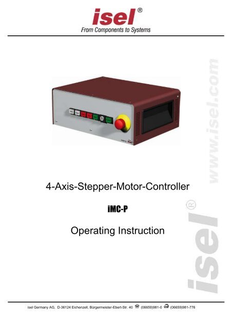
4-Axis-Stepper-Motor-Controller<br />
<strong>iMC</strong>-P<br />
<strong>Operating</strong> <strong>Instruction</strong><br />
isel Germany AG, D-36124 Eichenzell, Bürgermeister-Ebert-Str. 40 (06659)981-0 (06659)981-776
<strong>iMC</strong>-P – <strong>Operating</strong> <strong>Instruction</strong><br />
All information, technical data and dimensions contained in this booklet correspond to<br />
the technical state at the moment of publication. However, possible misprints or<br />
mistakes cannot be ruled out. We will appreciate all suggestions for improvement and<br />
error notes.<br />
We would like to point out that all used software and hardware names of the respective<br />
companies generally are subject to protection by brand, trademark and patent law.<br />
All rights reserved. It is prohibited to process, duplicate or reproduce this booklet<br />
partially or on the whole in any form (print, copy, or other procedure) without written<br />
permission of isel Germany AG.<br />
This booklet has been translated from the original German version into English<br />
language. It does not lay claim to completeness nor flawlessness. In case of doubt the<br />
German original has validity.<br />
isel controllers are concurrent with CE norms and marked accordingly.<br />
Commissioning of all other parts or components, for which CE safety<br />
regulations apply, is prohibited until all respective requests are met.<br />
isel Germany AG as the manufacturer cannot take over guarantee if you<br />
change the controller in any way.<br />
The EMC test is valid only for the controller’s original configuration ex<br />
works, i.e. the delivery state.<br />
Manufacturer:<br />
isel Germany AG<br />
Bürgermeister-Ebert-Straße 40<br />
D-36124 Eichenzell<br />
Tel.: (06659) 981-0<br />
Fax: (06659) 981-776<br />
Email: automation@isel.com<br />
http://www.isel.com<br />
Item-no.:<br />
970394 BE001<br />
(translation of operation instruction in german language)<br />
Status: 07/2013<br />
Technical specifications subject to change.<br />
Up to date <strong>Operating</strong> instructions and manuals for download you<br />
can find here:<br />
www.isel-data.de/manuals
Table of contents<br />
1 Introduction ....................................................................................................... 4<br />
1.1 Safety symbols .................................................................................................... 4<br />
1.2 Safety instructions................................................................................................ 4<br />
1.3 Intended use ........................................................................................................ 5<br />
2 Controller types ................................................................................................ 6<br />
3 Technical data ................................................................................................... 7<br />
4 Hardware description ....................................................................................... 9<br />
4.1 Front side <strong>iMC</strong>-P .................................................................................................. 9<br />
4.2 Back side <strong>iMC</strong>-P ................................................................................................ 11<br />
4.3 Assembly <strong>iMC</strong>-P ................................................................................................ 17<br />
4.4.1 <strong>iMC</strong>-P DIP-Switch settings .......................................................................................... 18<br />
5 Operation modes and operation .................................................................... 20<br />
5.1 Controller preparation ........................................................................................ 20<br />
5.2 CNC-mode <strong>iMC</strong>-P (with Core-module) ............................................................... 21<br />
5.3 Initial Operation and user programming in CNC-mode ...................................... 22<br />
5.3.1 Install programming software PALPC.exe ................................................................... 22<br />
5.3.2 PALPC- operation ....................................................................................................... 23<br />
5.4 DNC- mode <strong>iMC</strong>-P (with Core-Modul) ................................................................ 25<br />
5.5 Initial operation und user programming in DNC-mode ....................................... 26<br />
6 EC - Declaration of Conformity ...................................................................... 29<br />
7 Bibliography .................................................................................................... 30<br />
8 Index ................................................................................................................ 30
<strong>iMC</strong>-P – <strong>Operating</strong> <strong>Instruction</strong><br />
1 Introduction<br />
1.1 Safety symbols<br />
You will find different symbols in this manual that signalizes important information/<br />
facts and danger.<br />
Warning!<br />
This symbol indicates dangers that cause damages for person’s health,<br />
physical injury or death.<br />
Warning! Dangerous voltage!<br />
Warning of danger from electricity. Ignoring can lead to serious injury or<br />
death.<br />
Attention!<br />
This Symbol indicates important notes. Ignoring this symbol leads to<br />
damages and malfunctions of the machinery<br />
Information:<br />
This symbol indicates important information and notes.<br />
1.2 Safety instructions<br />
• The stepper-motor-controllers <strong>iMC</strong>-P are designed in conformability<br />
to current technical and recognized rules.<br />
• The device may only be used if it is in correct condition. Any faults<br />
have to be eliminated immediately. Neither children nor nonauthorized<br />
persons are allowed to put the device into operation.<br />
• The device may only be used for the intended purpose: control of 2<br />
up to 4 linear or rotational axes with 2-phase stepper motors.<br />
• All work with the controllers <strong>iMC</strong>-P, especially initial operation,<br />
installation as well as external wiring must be executed by authorized<br />
personal regarding electrical industry rules and accident prevention<br />
regulations.<br />
• Assembly and use of operating material has to be according to<br />
Machine directive 98/37/EC (valid until 28/12/2009) resp. 2006/42/EC<br />
(becomes operative from 29/12/2009) and Low voltage directive<br />
73/23/EWC. In case of in proper use even the observation of the<br />
respective rules and standards does not protect against physical<br />
damages and damage to property.<br />
• Do not expose the device to high humidity or high vibrations.<br />
• Please take care of the instruction manual. Be sure that all users<br />
know the instructions.<br />
• Ignoring the instruction manual can lead to damage, heavy physical<br />
damage or to death.<br />
page - 4
<strong>iMC</strong>-P – <strong>Operating</strong> <strong>Instruction</strong><br />
1.3 Intended use<br />
The stepper-motor-controller <strong>iMC</strong>-P is a freely programmable compact control for four<br />
linear or rotational units with 2-phase stepper motors. The controller integrates four<br />
motor power amplifiers with step/direction interface, a processor core with flash<br />
memory to interpret the user programs and generating step/direction signals for the<br />
power amplifiers, power supply units, security circuit module and a table housing with<br />
net input filter and control elements.<br />
The processors operating system (firmware) provides following operation modes:<br />
<br />
<br />
DNC-mode:<br />
The controller is permanent connected with a PC/laptop via serial interface.<br />
CNC-mode:<br />
The controller works „Stand Alone“ after a user program is downloaded to the<br />
processors flash memory.<br />
Both controllers are able to drive stepper-motors in micro stepping mode. The power<br />
amplifiers of the <strong>iMC</strong>-P generates up to 128 micro-steps per full-step. This allows a<br />
smoothly run of the connected motors. An automatic current reduction reduces the<br />
power loss in the amplifier and motor.<br />
The peak current amounts 4,2A and is adjustable via DIP-switches. With the impulse<br />
input it’s possible to control the most important functions (start, stop). Thereby it’s also<br />
possible to connect an external control console or a higher ranked control (e.g. PLC).<br />
All controllers have to be used only with the compatible motor type.<br />
Please read this operation instruction manual carefully before first use of the controller<br />
therewith you can:<br />
• Work safely, fast and effective<br />
• Keep away danger from persons<br />
• Use all the power and features of the controller.<br />
page - 5
<strong>iMC</strong>-P – <strong>Operating</strong> <strong>Instruction</strong><br />
2 Controller types<br />
The stepper motor controller <strong>iMC</strong>-P are available in two types. The first type has an<br />
intelligent core module which is controlled resp. programmed via RS232 or USB<br />
interface (in preparation). Commands in the user program will be processed and<br />
inverted to step/direction signals for the stepper motor amplifiers by the core module.<br />
Furthermore it’s possible to save a user program for the CNC mode<br />
(execution of a program without connected control PC) in the flash memory of the<br />
core module.<br />
The second type has instead of the core module a step/direction module. This module<br />
is used to connect the step/direction inputs of the power amplifiers to a connector<br />
(Sub-D-25-pin) in the back side of the controller. By means of this interface different<br />
control software are able to drive the stepper motor amplifiers via step/direction<br />
signals.<br />
<strong>iMC</strong>-P1 with core-module (Part.-No. 381403 000x 1 )<br />
stepper motor controller <strong>iMC</strong>-P with core-module as desk device with maximum<br />
four integrated stepper motor amplifiers MD24/MD28<br />
Main cable (protection contact plug, IEC-60320 power connector)<br />
RS232-communication cable, 9-pin Sub-D (socket) to 9-pin Sub-D (plug)<br />
<strong>Operating</strong> instruction<br />
<strong>iMC</strong>-P2 with step/direction-module (Part.-No. 381404 000x 1 )<br />
stepper motor controller <strong>iMC</strong>-P with step/direction-module as desk device with<br />
maximum four integrated stepper motor amplifiers MD24/MD28<br />
Main cable (protection contact plug, IEC-60320 power connector)<br />
<strong>Operating</strong> instruction<br />
1 x …number of amplifiers, 2 - 4<br />
page - 6
<strong>iMC</strong>-P – <strong>Operating</strong> <strong>Instruction</strong><br />
3 Technical data<br />
<strong>iMC</strong>-P<br />
General data:<br />
dimensions (W x H x D):<br />
375 x 140 x 260 mm<br />
weight:<br />
3 kg<br />
maximum number of axis: 4<br />
safety class:<br />
IP20<br />
ambient temperature:<br />
0°C - +50°C<br />
storage temperature:<br />
-20°C - +65°C<br />
humidity:<br />
maximum 90% not condensing<br />
Embedded controller data:<br />
controller core:<br />
program memory:<br />
communication via RS232:<br />
stepper motor amplifier:<br />
maximum input frequency:<br />
32Bit-RISC processor (embedded controller)<br />
512 Kbyte flash total, 16000 commands storable<br />
RS232 (19200 baud, 8 data bit, 1 stop bit, no parity)<br />
stepper motor power amplifier MD24<br />
40 kHz (full step)<br />
page - 7
<strong>iMC</strong>-P – <strong>Operating</strong> <strong>Instruction</strong><br />
electrical data:<br />
power supply voltage:<br />
wide range input 110 - 230VAC 50/60 Hz<br />
peak current per amplifier:<br />
4,2 A<br />
rated current per amplifier:<br />
3,5 A<br />
power supply voltage of the<br />
amplifiers:<br />
48 VDC<br />
automatic current reduction: to 60%<br />
digital inputs:<br />
8 x inputs<br />
digital outputs:<br />
8 x transistor outputs 24VDC/300 mA<br />
1 x relay output 230V/6A<br />
analog outputs: 1 x analog output 0…10V for speed control setting to a frequency inverter<br />
cover/door control:<br />
yes<br />
motor brake on Z-axis:<br />
yes<br />
safety data:<br />
EN ISO 13849-1:2006 category 2, PL c<br />
fuse:<br />
2 x 6,3A/250V time lag<br />
software for use with core-module:<br />
CNC mode:<br />
PALPC 2.1, @-format<br />
DNC mode:<br />
Remote (optional: ProNC)<br />
page - 8
<strong>iMC</strong>-P – <strong>Operating</strong> <strong>Instruction</strong><br />
4 Hardware description<br />
4.1 Front side <strong>iMC</strong>-P<br />
5 - operation mode switch (key switch)<br />
Use this switch to choose between automatic- and setup-mode.<br />
In automatic-mode (AUTO) you can only open the cover or safety<br />
door of the machine if no axis is in motion and the mounted<br />
working spindle is switched off (means that spindle does not turn).<br />
In the setup-mode (TEST) you can only open the cover or safety<br />
door of the machine if the mounted working spindle is switched off<br />
(means that spindle does not turn). You can just move the axes at<br />
opened cover or safety door if you press the ACK button.<br />
Ensure that in setup-mode (key switch on TEST) only authorized<br />
personal operates on the machine.<br />
6 - cover-button<br />
Use this button to open the machines cover or safety door. This is possible only if the<br />
conditions from point “4 – operation mode switch“ are complied. An enable for<br />
opening of the cover or safety door is signalized by a white lighted cover button.<br />
page - 9
<strong>iMC</strong>-P – <strong>Operating</strong> <strong>Instruction</strong><br />
7 - start-button<br />
If you press the start button in CNC mode (see chapter: 5.2) a saved user program in<br />
the flash memory will be executed.<br />
You cannot use the start switch in DNC mode.<br />
8 - fault-lamp<br />
The fault lamp indicates an error within the safety circuit.<br />
9 - emergency stop switch<br />
Turns off the power supply for the motor power amplifiers and the working spindle in<br />
case of any danger. This means dangers for the users health or machine safety. The<br />
integrated security circuit is applicable category 2 with PL c according to EN 13849-1.<br />
If you push the emergency stop switch the motor power supply will<br />
be switched off immediately and any axes motion will be stopped.<br />
The main power supply voltage of 115/230VAC lies still on the<br />
device, only the motor power supply voltage for the amplifiers is<br />
switched off.<br />
10 - power-button<br />
Use this button to switch on motor power supply voltage for the motor power<br />
amplifiers.<br />
Conditions for switch on:<br />
- Main power switch on the controller back side is switched on<br />
- Emergency stop button is pulled out<br />
Be sure that the contacts for external emergency stop switch<br />
on the remote connector are bridged!<br />
11 - stop-button<br />
If you press the stop button in CNC mode an active user program / axis motion will be<br />
stopped. You can continue the execution of the user program by pressing the start<br />
button.<br />
If you press the stop button in DNC mode an active user program / axis motion will<br />
be stopped. To continue the execution of the user program you have to use the<br />
controller software (ProNC, Remote).<br />
12 - ACK (ACKnowledge-button)<br />
This button has no function on 4-axis-controller MC-P.<br />
page - 10
<strong>iMC</strong>-P – <strong>Operating</strong> <strong>Instruction</strong><br />
4.2 Back side <strong>iMC</strong>-P<br />
<strong>iMC</strong>-P<br />
page - 11
<strong>iMC</strong>-P – <strong>Operating</strong> <strong>Instruction</strong><br />
Stepper-Motor connector – motor axis X-, Y-, Z-, A, Sub-D9-pin socket<br />
SubD-9-pin connector for motor modules (CNC axis)<br />
Connect / disconnect the Sub-D plug only if the controller is<br />
switched off. Ignoring this instruction can lead to damage the<br />
motor cable or stepper motor amplifier.<br />
pin description<br />
1 motor phase 2B<br />
2 motor phase 2A<br />
3 motor phase 1B<br />
4 motor phase 1A<br />
5 +24VDC<br />
6 brake (+24VDC/1,8A output with reference potential GND)<br />
7 limit switch 2 (Input +24VDC, if limit switch 2 is not actuated: NC<br />
8 GND<br />
9 limit switch 1 (Input +24VDC, if limit switch 1 is not actuated: NC<br />
The connection of a stepper motor with brake is only on the<br />
connector of the Z-axis possible. At this jack the switching signal<br />
(+24 V to pin 6) for the motor brake is provided.<br />
Remote - security circuit interface, 8-pin socket<br />
Use this connector to include the controller into a higher ranked security circuit<br />
system. Please note that the external power input is only useable if the power button<br />
from the controller front is switched off. That will be realized by bridging the pins 1 and<br />
2.<br />
pin<br />
description<br />
1 power button select<br />
2 power button select<br />
3 external power (make contact)<br />
4 +24V DC (external power)<br />
5 external emergency stop channel 1<br />
(brake contact, 11)<br />
6 external emergency stop channel 1<br />
(brake contact, 12)<br />
7 external emergency stop channel 2<br />
(brake contact, 21)<br />
8 external emergency stop channel 2<br />
(brake contact, 22)<br />
page - 12
<strong>iMC</strong>-P – <strong>Operating</strong> <strong>Instruction</strong><br />
Use external emergency stop:<br />
pin 5 and 6 bridged<br />
pin 7 and 8 bridged<br />
The length of the connection cable for the external emergency<br />
stop button must not more than 5m.<br />
Use external power button:<br />
pin 1 and 2 bridged<br />
connect external power button (make contact) on pin 3 and 4<br />
In case of an emergency stop the +24VDC voltage on pin 4 is no<br />
longer available.<br />
Impulse - interface impulse control, 8-pin connector<br />
Use this connector to integrate the function keys start button, stop button and reset<br />
from the controller front side as external signal inputs.<br />
pin description<br />
1 input external START button (make contact)<br />
2 +24VDC<br />
3 input external STOP button (brake contact)<br />
4 output lamp START button<br />
5 GND<br />
6 output lamp STOP button<br />
7 input length measure switch<br />
8 +24VDC<br />
If the external STOP button is not used pins 2 and 3 must be<br />
bridged.<br />
In case of an emergency stop the +24VDC voltage on pin 2 is<br />
no longer available.<br />
Input - digital inputs, 8-pin connector<br />
The controller has 8 digital user inputs. Use these inputs to connect external devices<br />
like sensors, switches or outputs from other devices. All inputs are opto-decoupled. If<br />
+24VDC lies on the input a logical HIGH is signalized. Not connected (e.g. switch<br />
open) a logical LOW is signalized.<br />
Do not short 24VDC reference potential of the controller with<br />
GND or case ground.<br />
page - 13
<strong>iMC</strong>-P – <strong>Operating</strong> <strong>Instruction</strong><br />
The binary user inputs 1 – 8 must be<br />
wired as shown opposite.<br />
The load of the controller internal 24V<br />
power supply unit amounts on 1-active<br />
state 4 mA per input.<br />
Output - digital outputs, 8-pin connector<br />
The controller has 8 digital user outputs. Use these outputs to connect external<br />
devices like relays, or inputs from other devices. The maximum load of each relay<br />
output is 24 VDC/300 mA.<br />
Do not short 24VDC potential of the controller with GND or<br />
case ground.<br />
If you have pushed the emergency stop switch all states of the<br />
binary user outputs will be maintained and not reset!<br />
The binary user output 1 – output 8 must<br />
be wired as shown opposite.<br />
The transistor outputs (output 1 – 8) can<br />
be rated with 300 mA per output.<br />
If all outputs are switched (1-active) the<br />
maximum load of the internal 24VDC<br />
power supply unit is 1, 5 A (ca. 180mA<br />
per output).<br />
page - 14
<strong>iMC</strong>-P – <strong>Operating</strong> <strong>Instruction</strong><br />
Analog - Out, Sub-D9-pin connector<br />
Use this connector to drive an external frequency inverter with the corresponding<br />
working spindle via a 0 – 10 V analog output.<br />
pin description<br />
1 +24VDC<br />
2 n.u.<br />
3 n.u.<br />
4 make contact 1(potential free contact)<br />
5 analog 0 ...10V<br />
6 GND<br />
7 n.u.<br />
8 make contact 1(potential free contact)<br />
9 GND<br />
Cover - Sub-D9-pin connector<br />
This connector is used to integrate a solenoid interlock to the security circuit of the<br />
controller.<br />
On isel machines the solenoid interlock is realized by a switch of<br />
type:<br />
SCHMERSAL EX-AZM 170-02ZK-24V (part-no. 577047 0800)<br />
Only this type interlocks or interlocks with the same functionality<br />
have to be used.<br />
pin description<br />
1 + coil break contact<br />
2 switch 1.1 (bridge to pin 3 if no safety door is used)<br />
3 switch 1.2 (bridge to pin 2 if no safety door is used<br />
4 switch 2.1 (bridge to pin 5 if no safety door is used<br />
5 switch 2 .2 (bridge to pin 4 if no safety door is used<br />
6 - coil break contact<br />
7 - 9 n.u.<br />
If no cover or safety door is used the pins 2, 3 and 4, 5 must be<br />
bridged. Therefore use the enclosed Sub-D 9-pin plug.<br />
If the contacts of the interlock is interrupted (e.g. forcible opening of<br />
the hood or remove the jumper, Sub-D) will immediately trigger an<br />
emergency stop and turned off the spindle.<br />
page - 15
<strong>iMC</strong>-P – <strong>Operating</strong> <strong>Instruction</strong><br />
Spindle - 115/230V output, 3-poles<br />
Use this output connector to directly tap a working spindle without speed control. Use<br />
the delivered mating connector. Maximum load of the relay output is 230 V AC / 6A.<br />
AC-Input - net input module 115/230 VAC, 50 - 60 Hz<br />
The net input module consists of net input socket, net filter, fuse holder and net main<br />
switch. Connect the controller via delivered net cable to a free receptacle. After that<br />
you can switch on the controller with the net main switch.<br />
RS232 (PC) – programming interface<br />
Communication between <strong>iMC</strong>-P and control PC is realized via a serial interface<br />
(RS232). Use the delivered communication (null modem) cable for connection.<br />
A software protocol realizes the faultless transmission of the ASCII characters.<br />
Therefore it’s necessary that both systems respect the communication protocol:<br />
The connected control PC sends a command which ends with a line end<br />
character [CR, char (13)].<br />
The processor unit quits the execution or storing of a command with the<br />
quitting signal 0[char (48)] or returns an occurred error with an ASCII character<br />
unequal 0.<br />
Data transfer parameters:<br />
- 19200 baud<br />
- 8 data bits<br />
- 1 stop bit<br />
- no parity<br />
page - 16
<strong>iMC</strong>-P – <strong>Operating</strong> <strong>Instruction</strong><br />
4.3 Assembly <strong>iMC</strong>-P<br />
base board with embedded<br />
controller and relays<br />
net input module with net filter,<br />
main switch and fuses<br />
4 x stepper motor<br />
power amplifier MD24<br />
switching power supply<br />
input 115/230 VAC<br />
output 48VDC, 500W<br />
switching power supply<br />
input 115/230 VAC<br />
output 24VDC, 60W<br />
function keys module<br />
with switches, buttons in<br />
the controller case front<br />
security circuit board with<br />
safety relays<br />
page - 17
<strong>iMC</strong>-P – <strong>Operating</strong> <strong>Instruction</strong><br />
4.4.1 <strong>iMC</strong>-P DIP-Switch settings<br />
The controller <strong>iMC</strong>-P has four stepper motor power amplifiers MD24. Settings for<br />
rated current, step resolution and current reduction takes place by the DIP-switch on<br />
the top side of the amplifiers case.<br />
Configuration of the controller should be done before first start-up<br />
so that a connected motor will not be damaged because of an<br />
incorrect power setting.<br />
To configure the step resolution and motor current open the cover and set the jumper<br />
on each amplifier as follows (more information /1/ Microstepping Driver MD24/MD28):<br />
DIP Switch - MD24 in <strong>iMC</strong>-P<br />
1: current setting 1<br />
2: current setting 2<br />
3: current setting 3<br />
4: current reduction<br />
5: step resolution 1<br />
6: step resolution 2<br />
7: step resolution 3<br />
8: step resolution 4<br />
Current setting (DIP-switch 1, 2, 3)<br />
Use the DIP switches 1, 2 and 3 to set the current of the motor. The following table<br />
shows the motor current (RMS) setting for the different switch positions:<br />
The factory set of the motor current is 2,03 A (RMS)on all motor<br />
power amplifiers.<br />
page - 18
<strong>iMC</strong>-P – <strong>Operating</strong> <strong>Instruction</strong><br />
Current reduction (DIP-switch 4)<br />
Use the DIP switch 4 to set the automatic current reduction. If the DIP switch is set to<br />
ON the automatic current reduction is deactivated. DIP switch in state OFF means<br />
that the current is set to 50% of the motor current if the motor standstill.<br />
DIP 4 current reduction in %<br />
ON 0% reduction (deactivated)<br />
OFF 50% reduction<br />
If the holding torque is sufficient, the activated automatic current<br />
reduction is recommended.<br />
Step resolution (DIP-switch 5, 6, 7, 8)<br />
Use the DIP switches 5, 6, 7 and 8 to set the step resolution. Setting the factor to a<br />
higher value causes a smooth motion of the motor but the maximum reachable<br />
velocity will taking down. Also the motor torque will be reduced to 75% in microstep<br />
mode. The following table shows the DIP switch settings for the different step<br />
resolutions:<br />
The Factory set of the step resolution is 800 steps/rev for all motor<br />
power amplifiers.<br />
page - 19
<strong>iMC</strong>-P – <strong>Operating</strong> <strong>Instruction</strong><br />
5 Operation modes and operation<br />
The processors operating system (firmware processor core) provides the following<br />
operation modes:<br />
<br />
<br />
DNC-mode:<br />
• PC/Laptop is permanent connected to the 4-axis-controller via<br />
serial interface<br />
• Software Remote/ProNC is used to drive the controller<br />
CNC-mode:<br />
• 4-axis-controller executes user programs stand alone without a<br />
connected PC/Laptop<br />
• Software PALPC 2.1 is used for programming and download of<br />
user programs into the flash memory of the controller<br />
5.1 Controller preparation<br />
Before first startup of the controller please check the scope of delivery.<br />
The following parts should be included:<br />
<br />
<br />
<br />
<br />
<br />
4-axis-stepper-motor-controller <strong>iMC</strong>-P as desk device<br />
Net power supply cable 115/230VAC<br />
RS232-communication cable,<br />
9-pin Sub-D (female) to 9-pin Sub-D (female)<br />
Bridging connectors<br />
<strong>Operating</strong> instruction<br />
If all this parts are included you can begin initial operation.<br />
Provide all electrical connections.<br />
Connectors<br />
- Connect net power supply cable<br />
- Connect axis (motors) on the controller back side<br />
Configuration<br />
- Set DIP-switches / jumper for motor current, step resolution, current reduction,<br />
motor brakeq (see chapter Fehler! Verweisquelle konnte nicht gefunden<br />
werden. and 4.4.1 )<br />
Initial operation<br />
- Switch on controller with main power switch on the back side<br />
- Check if emergency switch is pulled out<br />
- Push power button on the front of the controller<br />
Power button should be lighted green – controller is ready for work<br />
Operation mode<br />
- Use the 4-axis-controller in CNC- or DNC-mode<br />
page - 20
<strong>iMC</strong>-P – <strong>Operating</strong> <strong>Instruction</strong><br />
5.2 CNC-mode <strong>iMC</strong>-P (with Core-module)<br />
The CNC mode (automatic mode = CNC mode) is the program controlled mode of the<br />
4-axis-stepper-motor-controller <strong>iMC</strong>-P.<br />
That means that a user program which is saved in the controller’s memory (flash) will<br />
be executed till the end.<br />
During the automatic mode (CNC mode) you can stop the execution of the active user<br />
program by pressing the STOP-key on front side of the controller or by using the<br />
external Stop input. A following operation of the START-key on the front side of the<br />
controller or the activation (1-active) of the external start input effects the resumption<br />
of the automatic mode.<br />
With motor cable connected axis<br />
(linear or rotation axis) will be driven<br />
by user program commands<br />
Binary inputs connected to the input port<br />
will be interpreted.<br />
Binary outputs connected to the output port<br />
will be set/reset by user program.<br />
page - 21
<strong>iMC</strong>-P – <strong>Operating</strong> <strong>Instruction</strong><br />
5.3 Initial Operation and user programming in CNC-mode<br />
Creating user programs for 4-axis-controller <strong>iMC</strong>-P is realized with the software<br />
PALPC.exe. The implementation method is simple and described in “/2/ PAL-PC<br />
programming instruction“:<br />
Analyze technological problem definition:<br />
Layout program algorithm (solve problem definition)<br />
Implementation of the control algorithm into a PALPC source program *.ppc; edit<br />
code with text editor<br />
Compile PALPC source file with PALPC compiler; on faultless translation an<br />
output file *.out is created by the compiler<br />
Download output file *.out into the flash memory of 1-axis-controller MC1<br />
Start program and check control behavior regarding technological problem<br />
definition<br />
5.3.1 Install programming software PALPC.exe<br />
To install PALPC software do the following:<br />
1. Insert PALPC 2.1 installation medium (delivered CD or USB stick) with the control<br />
computer.<br />
2. Following Auto-start-window will be shown (when installing from CD):<br />
If Auto-Start-window is not shown start the Windows Explorer<br />
and open the root directory of the CD/DVD- or USB-drive. Double<br />
click on the file “Autorun.exe“.<br />
page - 22
<strong>iMC</strong>-P – <strong>Operating</strong> <strong>Instruction</strong><br />
3. Click on “Install PAL PC” and follow the installation instructions.<br />
PALPC installation assistant installation dialog:<br />
4. Start PALPC.exe via start menu entry or desktop shortcut. On first startup an<br />
activation window will be shown. Enter delivered registration data (serial number<br />
and activation code) into the dialogs edit fields.<br />
5.3.2 PALPC- operation<br />
The use of PALPC and user programming are described in /1/ PALPC user manual<br />
and /2/ PALPC programming instruction.<br />
For 4-axis-controller <strong>iMC</strong>-P note following specialties:<br />
page - 23
<strong>iMC</strong>-P – <strong>Operating</strong> <strong>Instruction</strong><br />
1. The declaration<br />
#control IMC4;<br />
defines target controller as IMC4 compatible controller like 4-axis-controller <strong>iMC</strong>-P<br />
2. The declaration<br />
#axis xyza;<br />
defines the axis that will be used, in this case four axis: x, y, z and a<br />
3. The declaration<br />
#steps 800;<br />
defines the step resolution set by DIP switch<br />
e.g. #steps 800; /4 micro steps per full step * 200 full steps/motor revolution<br />
4. The declaration<br />
defines the spindle elevation of the connected linear axis,<br />
e.g. #elev 5,5,5,4 /elevation 5mm for xyz-axis, 4mm for a-axis<br />
#elev 360°/ transmission ratio;<br />
defines the transmission ratio of the connected rotary axis,<br />
e.g. ZR20 with transmission ratio 1:20:<br />
360<br />
18 #elev 18;<br />
20<br />
page - 24
<strong>iMC</strong>-P – <strong>Operating</strong> <strong>Instruction</strong><br />
5.4 DNC- mode <strong>iMC</strong>-P (with Core-Modul)<br />
In DNC mode the 4-axis-controller controller <strong>iMC</strong>-P with core-module is connected<br />
permanently via RS-232 interface with a control PC (IBM compatible PC or<br />
Notebook).<br />
A user program stored in flash memory will not be executed. The commands to<br />
execute an action/motion (e.g. reference motion, motion of the axis or I/O actions) will<br />
be sent by user software from the PC with the new Remote/ProNC motion control for<br />
4-axis-controller (IMC4 compatibility mode).<br />
Necessary COM interface on PC:<br />
9-pin Sub-D (male)<br />
serial interface cable:<br />
9-pin Sub-D (female) to 9-pin<br />
Sub-D (female) is within the<br />
scope of delivery<br />
COM interface on controller:<br />
9-pin Sub-D (male), labeled with<br />
„RS-232 (PC)“<br />
Image: serial connection (RS-232) between PC / Notebook and <strong>iMC</strong>-P via interface cable<br />
Likewise in this configuration can be done:<br />
PALPC 2.1 user program download into the flash memory of<br />
the 4-axis-controller <strong>iMC</strong>-P.<br />
(COM Interface for PALPC: 19200 Bit/sec, PalPC.exe)<br />
page - 25
<strong>iMC</strong>-P – <strong>Operating</strong> <strong>Instruction</strong><br />
5.5 Initial operation und user programming in DNC-mode<br />
User programming and control of the 4-axis-controller <strong>iMC</strong>-P in DNC-mode takes<br />
place by the programs Remote or ProNC by binding the corresponding motioncontrol-DLL<br />
file. Commands in the user program will be send to the 4-axis-controller.<br />
Installation of the control software Remote<br />
Do the following steps to install setup software:<br />
1. Insert Remote installation medium (delivered CD or USB stick) with the control<br />
computer.<br />
2. An Auto-start-window will be shown (when installing from CD):<br />
If Auto-Start-window is not shown start the Windows Explorer<br />
and open the root directory of the CD/DVD- or USB-drive. Double<br />
click on the file “Autorun.exe“.<br />
3. Click on the entry “Installation of Remote“.<br />
Choose your language and follow the instructions of the setup assistant.<br />
page - 26
<strong>iMC</strong>-P – <strong>Operating</strong> <strong>Instruction</strong><br />
4. Mark on setup window “Select control“ the option “Stepper motor control IMC4“ to<br />
install the IMC4 stepper motor driver module.<br />
After finishing the installation click on button “Exit“ to close the Auto-Start-menu.<br />
5. Open the control software Remote via shortcut on the windows desktop or the<br />
start menu entry: Start Programs CNCworkbench Remote<br />
6. On first startup of the software Remote you have to type in a serial number and an<br />
activation code. You will find this information on the delivered registration formular.<br />
Click on button „Next“ to check the registration data. If the data is ok Remote will<br />
starting.<br />
page - 27
<strong>iMC</strong>-P – <strong>Operating</strong> <strong>Instruction</strong><br />
Use of the controller <strong>iMC</strong>-P with Remote<br />
Using <strong>iMC</strong>-P (with Core module) with Remote via serial interface:<br />
1. Start control software Remote. If you don’t have activated Remote you have to do<br />
it now.<br />
2. After installation of Remote for a specific control (in this case IMC4) all module<br />
DLL’s for the motion control, I/O module, spindle module and security circuit<br />
module are set correctly. You only have to set the parameters to your machine<br />
configuration. Click in the main menu to the entry Settings Control<br />
The dialog shows all<br />
active and used<br />
modules in a list.<br />
Mark the line “Motion<br />
Control” and click on<br />
button “Setup” on the<br />
right side to show the<br />
settings for<br />
communication and axis<br />
kinematics.<br />
Over the different register cards you<br />
can change the parameters like axis<br />
direction, spindle gradient, gear etc.<br />
for each separate axis. Over the<br />
register card “Data transmission” you<br />
can change the used COM Port of the<br />
control computer.<br />
3. If you have set all parameters close the dialog with the button „OK“.<br />
Click on button “Close & Initialize” in the “Control module and settings” dialog to<br />
take effect the new settings and reinitialize the control.<br />
4. Perform a software reset and a reference run to check correct<br />
behaviour of the machine /system.<br />
Additional information to configure Remote you can find in the<br />
online help (menu help, F1 key).<br />
page - 28
6 EC - Declaration of Conformity<br />
Der Hersteller<br />
The manufacturer<br />
isel Germany AG<br />
Bürgermeister-Ebert-Str. 40<br />
D-36124 Eichenzell<br />
erklärt hiermit, dass folgendes Produkt<br />
hereby declares that the following product<br />
Geräteart:<br />
Device:<br />
Typ:<br />
Type:<br />
Art.-Nr.:<br />
Product - No.:<br />
4-Achs-Schrittmotor-Controller<br />
4-axis-stepper-motor-controller<br />
<strong>iMC</strong>-P<br />
<strong>iMC</strong>-P: 381403 000x, 381404 000x<br />
mit den Vorschriften folgender Europäischer Richtlinien übereinstimmt:<br />
complies with the requirements of the European Directives:<br />
EG-Richtlinie 2004/108/EG<br />
EC-Directive 2004/108/EC<br />
EG-Richtlinie 73/23/EWG<br />
EC-Directive 73/23/ECC<br />
EMV Richtlinie<br />
EMC directive<br />
Niederspannungsrichtlinie<br />
low voltage directive<br />
Folgende harmonisierte Normen wurden angewandt:<br />
Following harmonized standards have been applied:<br />
EN 61000-6-2:2005<br />
EN 61000-4-2:2007<br />
EN 61000-4-4:2004<br />
EN 61000-4-5:2006<br />
EN 61000-4-11:2004<br />
EN 61000-6-4:2007<br />
DIN EN 55011:2007<br />
EMV - Fachgrundnorm - Störfestigkeit für Industriebereich<br />
EMC - Generic standards - Immunity for industrial environments<br />
EMV - Prüf- und Messverfahren - Prüfung der Störfestigkeit gegen Entladung<br />
statischer Elektrizität (ESD)<br />
EMC - Testing and measurement techniques; Electrostatic discharge immunity test<br />
EMV - Prüf- und Messverfahren - Prüfung der Störfestigkeit gegen schnelle<br />
transiente elektrische Störgrößen (Burst)<br />
EMC - Testing and measurement techniques - Electrical fast transient/burst immunity test<br />
EMV - Prüf- und Messverfahren - Prüfung der Störfestigkeit gegen<br />
energiereiche Impulse (Surge)<br />
EMC - Testing and measurement techniques - Surge immunity test<br />
EMV - Prüf- und Messverfahren - Prüfung der Störfestigkeit gegen<br />
Spannungs-einbrüche / Spannungsunterbrechungen<br />
EMC - Testing and measurement techniques - Voltage dips, short interruptions and voltage<br />
variations immunity tests<br />
EMV - Fachgrundnorm - Störaussendung Industriebereich<br />
EMC - Generic standards - Emission standard for industrial environments<br />
Industrielle, wissenschaftliche und medizinische Hochfrequenzgeräte (ISM-<br />
Geräte) - Funkstörungen - Grenzwerte und Messverfahren<br />
Industrial scientific and medical (ISM) radio-frequency equipment - Electromagnetic<br />
disturbance characteristics - Limits and methods of measurement<br />
Dermbach, 02.08.2009<br />
__________________________________<br />
Hugo Isert, Vorstandsvorsitzender / chairman
7 Bibliography<br />
/1/ Microstepping Driver MD24/MD28, Hardware Description, 02/2009<br />
/2/ PAL PC 2.0 <strong>Operating</strong> instruction, status 06/2004<br />
/4/ ProNC <strong>Operating</strong> instruction, status 2003<br />
<strong>Operating</strong> instructions and manuals for download you can find here:<br />
www.isel-data.de/manuals<br />
8 Index<br />
#control 26<br />
#steps 26<br />
ACK 10<br />
activation code 25<br />
Analog - Out 15<br />
CNC mode 8, 23<br />
core modul 6<br />
Cover 15<br />
current reduction 21<br />
current setting 20<br />
digital inputs 8<br />
digital outputs 8<br />
DNC mode 8<br />
DNC-mode 27<br />
emergency stop switch 10<br />
external emergency stop 13<br />
flash memory 27<br />
harmonized standards 31<br />
input frequency 7<br />
#<br />
A<br />
C<br />
D<br />
E<br />
F<br />
H<br />
I<br />
installation dialog 25<br />
intended use 4<br />
Interface cable 27<br />
interface impulse control 13<br />
Low voltage directive 4<br />
Operation mode switch 9<br />
output file 24<br />
PALPC compiler 24<br />
PALPC.exe 24<br />
peak current 8<br />
power-button 10<br />
program memory 7<br />
ProNC 27<br />
rated current 8<br />
Remote 27<br />
RS232 16<br />
security circuit interface 12<br />
serial number 25<br />
Spindle 15<br />
start-button 10<br />
step resolution 21<br />
stop-button 10<br />
text editor 24<br />
L<br />
O<br />
P<br />
R<br />
S<br />
T