Application of Paramics Simulation to a Diamond Interchange
Application of Paramics Simulation to a Diamond Interchange
Application of Paramics Simulation to a Diamond Interchange

You also want an ePaper? Increase the reach of your titles
YUMPU automatically turns print PDFs into web optimized ePapers that Google loves.
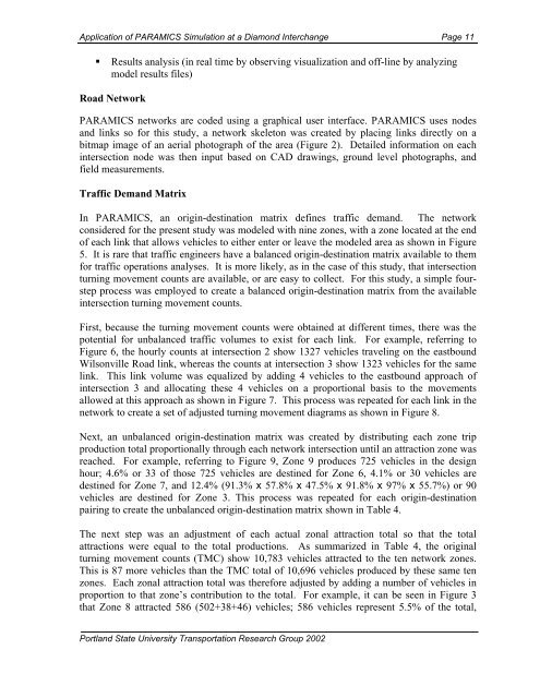
<strong>Application</strong> <strong>of</strong> PARAMICS <strong>Simulation</strong> at a <strong>Diamond</strong> <strong>Interchange</strong> Page 11<br />
• Results analysis (in real time by observing visualization and <strong>of</strong>f-line by analyzing<br />
model results files)<br />
Road Network<br />
PARAMICS networks are coded using a graphical user interface. PARAMICS uses nodes<br />
and links so for this study, a network skele<strong>to</strong>n was created by placing links directly on a<br />
bitmap image <strong>of</strong> an aerial pho<strong>to</strong>graph <strong>of</strong> the area (Figure 2). Detailed information on each<br />
intersection node was then input based on CAD drawings, ground level pho<strong>to</strong>graphs, and<br />
field measurements.<br />
Traffic Demand Matrix<br />
In PARAMICS, an origin-destination matrix defines traffic demand. The network<br />
considered for the present study was modeled with nine zones, with a zone located at the end<br />
<strong>of</strong> each link that allows vehicles <strong>to</strong> either enter or leave the modeled area as shown in Figure<br />
5. It is rare that traffic engineers have a balanced origin-destination matrix available <strong>to</strong> them<br />
for traffic operations analyses. It is more likely, as in the case <strong>of</strong> this study, that intersection<br />
turning movement counts are available, or are easy <strong>to</strong> collect. For this study, a simple fourstep<br />
process was employed <strong>to</strong> create a balanced origin-destination matrix from the available<br />
intersection turning movement counts.<br />
First, because the turning movement counts were obtained at different times, there was the<br />
potential for unbalanced traffic volumes <strong>to</strong> exist for each link. For example, referring <strong>to</strong><br />
Figure 6, the hourly counts at intersection 2 show 1327 vehicles traveling on the eastbound<br />
Wilsonville Road link, whereas the counts at intersection 3 show 1323 vehicles for the same<br />
link. This link volume was equalized by adding 4 vehicles <strong>to</strong> the eastbound approach <strong>of</strong><br />
intersection 3 and allocating these 4 vehicles on a proportional basis <strong>to</strong> the movements<br />
allowed at this approach as shown in Figure 7. This process was repeated for each link in the<br />
network <strong>to</strong> create a set <strong>of</strong> adjusted turning movement diagrams as shown in Figure 8.<br />
Next, an unbalanced origin-destination matrix was created by distributing each zone trip<br />
production <strong>to</strong>tal proportionally through each network intersection until an attraction zone was<br />
reached. For example, referring <strong>to</strong> Figure 9, Zone 9 produces 725 vehicles in the design<br />
hour; 4.6% or 33 <strong>of</strong> those 725 vehicles are destined for Zone 6, 4.1% or 30 vehicles are<br />
destined for Zone 7, and 12.4% (91.3% x 57.8% x 47.5% x 91.8% x 97% x 55.7%) or 90<br />
vehicles are destined for Zone 3. This process was repeated for each origin-destination<br />
pairing <strong>to</strong> create the unbalanced origin-destination matrix shown in Table 4.<br />
The next step was an adjustment <strong>of</strong> each actual zonal attraction <strong>to</strong>tal so that the <strong>to</strong>tal<br />
attractions were equal <strong>to</strong> the <strong>to</strong>tal productions. As summarized in Table 4, the original<br />
turning movement counts (TMC) show 10,783 vehicles attracted <strong>to</strong> the ten network zones.<br />
This is 87 more vehicles than the TMC <strong>to</strong>tal <strong>of</strong> 10,696 vehicles produced by these same ten<br />
zones. Each zonal attraction <strong>to</strong>tal was therefore adjusted by adding a number <strong>of</strong> vehicles in<br />
proportion <strong>to</strong> that zone’s contribution <strong>to</strong> the <strong>to</strong>tal. For example, it can be seen in Figure 3<br />
that Zone 8 attracted 586 (502+38+46) vehicles; 586 vehicles represent 5.5% <strong>of</strong> the <strong>to</strong>tal,<br />
Portland State University Transportation Research Group 2002