Deflection of an Electron in a Magnetic Field
Deflection of an Electron in a Magnetic Field
Deflection of an Electron in a Magnetic Field

Create successful ePaper yourself
Turn your PDF publications into a flip-book with our unique Google optimized e-Paper software.
Name:<br />
Partners:<br />
Date:<br />
<strong>Deflection</strong> <strong>of</strong> <strong>an</strong> <strong>Electron</strong> <strong>in</strong> a <strong>Magnetic</strong> <strong>Field</strong><br />
Purpose<br />
In this lab, we use a Cathode Ray Tube (CRT) to measure the effects <strong>of</strong> <strong>an</strong> electric <strong>an</strong>d<br />
magnetic field on the motion <strong>of</strong> a charged particle, <strong>in</strong> this case the electron.<br />
Theory<br />
The Lorentz force law, Equation 1, tells us that a charged particle experiences a force <strong>in</strong><br />
<strong>an</strong> area where there exists <strong>an</strong> electric or magnetic field.<br />
r<br />
F = q E r<br />
+ v r " B<br />
r<br />
( ) (1)<br />
where F is the force exerted on the charged particle, q is the charge <strong>of</strong> the particle, E is<br />
the electric field, v is the velocity <strong>of</strong> the charged particle <strong>an</strong>d B is the magnetic field.<br />
When <strong>an</strong> electron (q = -e), ! is <strong>in</strong> a magnetic field, where E = 0, the electron experiences a<br />
force given by Equation 2.<br />
r<br />
F = "e v r # B<br />
r<br />
( ) (2)<br />
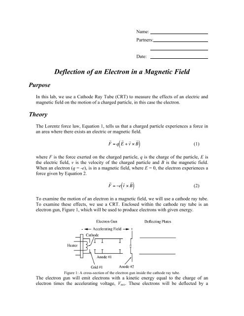
To exam<strong>in</strong>e the motion <strong>of</strong> <strong>an</strong> electron <strong>in</strong> a magnetic field, we will use a cathode ray tube.<br />
To exam<strong>in</strong>e these effects, we use a CRT. Enclosed with<strong>in</strong> the cathode ray tube is <strong>an</strong><br />
electron gun, Figure 1, which ! will be used to produce electrons with given energy.<br />
Figure 1: A cross-section <strong>of</strong> the electron gun <strong>in</strong>side the cathode ray tube.<br />
The electron gun will emit electrons with a k<strong>in</strong>etic energy equal to the charge <strong>of</strong> <strong>an</strong><br />
electron times the accelerat<strong>in</strong>g voltage, V acc . These electrons will be deflected by a
magnetic field that is generated by a current-carry<strong>in</strong>g wire. In this setup, the electron is<br />
mov<strong>in</strong>g perpendicular to the magnetic field. Thus, the force on the electron is:<br />
F = evB (3)<br />
Additionally, we know from last semester that, when the force act<strong>in</strong>g on a body is<br />
perpendicular to the motion, the result<strong>in</strong>g motion is circular. Us<strong>in</strong>g this <strong>an</strong>d conservation<br />
<strong>of</strong> energy SHOW that the electrons<br />
!<br />
will move <strong>in</strong> a circle <strong>of</strong> radius R, given <strong>in</strong> equation 4:<br />
R = m eB<br />
2eV acc<br />
m<br />
(4)<br />
The radius <strong>of</strong> curvature is related to the spot that is made on the screen, as seen <strong>in</strong><br />
Figure 2. The electron beam is travel<strong>in</strong>g from the left (where it is emitted by the electron<br />
gun) to the <strong>an</strong>ode, <strong>an</strong>d then ! on towards the screen. In the absence <strong>of</strong> a magnetic field this<br />
trajectory would be a straight l<strong>in</strong>e path, a dist<strong>an</strong>ce S long; however, when a magnetic<br />
field is added (<strong>in</strong>to the page) the electron beam will curve away from its orig<strong>in</strong>al course,<br />
as seen <strong>in</strong> Figure 1.<br />
34
Figure 2<br />
If the magnetic field is uniform, the force will be const<strong>an</strong>t <strong>an</strong>d the radius <strong>of</strong> curvature, R,<br />
is fixed. We c<strong>an</strong> use geometry to determ<strong>in</strong>e how R is related to measurable qu<strong>an</strong>tities.<br />
1. ∆ BAC is similar to ∆ DEB, s<strong>in</strong>ce 2 sides are mutually perpendicular.<br />
2. Us<strong>in</strong>g the Pythagore<strong>an</strong> theorem:<br />
( BC ) 2 = S 2 + x 2<br />
3. For similar tri<strong>an</strong>gles, the ratio <strong>of</strong> sides is equal. Also,<br />
!<br />
( )<br />
x<br />
( BC) = BE 1<br />
R = BC 2<br />
! R<br />
4. From this, you should be able to SHOW:<br />
( )<br />
DE bisects<br />
!<br />
BC . Thus:<br />
!<br />
2Rx = ( BC) 2<br />
5. Us<strong>in</strong>g our result from l<strong>in</strong>e 2 <strong>an</strong>d some algebra, you should be able to SHOW:<br />
!<br />
R = S 2 + x 2<br />
2x<br />
" S 2<br />
2x<br />
(5)<br />
where x is the deflection <strong>of</strong> the electron beam <strong>an</strong>d S = 0.213m for the tubes used <strong>in</strong> this<br />
lab.<br />
!<br />
35
Us<strong>in</strong>g equations 4 <strong>an</strong>d 5, we f<strong>in</strong>d a prelim<strong>in</strong>ary expression for the deflection, x, <strong>in</strong> terms<br />
<strong>of</strong> the magnetic field strength:<br />
S 2<br />
2x " 1 B<br />
2mV acc<br />
e<br />
(6)<br />
We c<strong>an</strong>not measure the strength <strong>of</strong> the magnetic field directly, but we c<strong>an</strong> express it <strong>in</strong><br />
terms <strong>of</strong> the current that produces it. To simplify the math, we will make <strong>an</strong>other<br />
approximation. The extreme ! oblong rect<strong>an</strong>gular geometry <strong>of</strong> the coils used to generate<br />
the magnetic field, B, me<strong>an</strong>s that the two “far ends” contribute relatively little. As such,<br />
the coil c<strong>an</strong> be thought <strong>of</strong> as two sets <strong>of</strong> N long wires, where N is the number <strong>of</strong> turns <strong>in</strong><br />
the coil. The magnetic field generated by a s<strong>in</strong>gle long straight wire:<br />
B = µ o I<br />
2"a<br />
(7)<br />
where a is the dist<strong>an</strong>ce from the wire to the electron beam, I is the current which is<br />
generat<strong>in</strong>g B, <strong>an</strong>d µ 0<br />
= 4 π × 10 -7 Tesla·m/Amp.<br />
!<br />
The magnetic field produced by the current <strong>in</strong> the top wire adds to the magnetic field<br />
produced by the current <strong>in</strong> the bottom wire. The wires on the top are about the same<br />
dist<strong>an</strong>ce ! from the electron beam as the wires on the bottom. S<strong>in</strong>ce we are treat<strong>in</strong>g our<br />
coils as two sets <strong>of</strong> N wires, the magnetic field is:<br />
#<br />
B = B top<br />
+ B bottom<br />
= N %<br />
$<br />
µ oI<br />
2"a top<br />
&<br />
( + N # µ o<br />
I<br />
%<br />
' $<br />
2"a bottom<br />
&<br />
( = µ oNI<br />
' "a<br />
(8)<br />
Substitut<strong>in</strong>g this result <strong>in</strong>to Equation 6 <strong>an</strong>d simplify<strong>in</strong>g, you should be able to SHOW:<br />
!<br />
e m<br />
x = µ NS 2<br />
o<br />
2 2" a<br />
I<br />
V acc<br />
(9)<br />
Procedure<br />
!<br />
The apparatus will be pre-wired, as described below. Exam<strong>in</strong>e the wir<strong>in</strong>g, mak<strong>in</strong>g sure<br />
that it agrees with what is described below. Once you th<strong>in</strong>k it is correct, call the <strong>in</strong>structor<br />
or TA over to look at it before turn<strong>in</strong>g <strong>an</strong>y power supply on. The circuit diagram for the<br />
CRT control box (the alum<strong>in</strong>um box at your station) is seen below, <strong>in</strong> Figure 3.<br />
36
Figure 3<br />
As before, all <strong>of</strong> the voltages needed by the oscilloscope box <strong>in</strong> this lab are produced by<br />
the HeathKit Regulated power Supply, Model IP-32. A separate power supply provides<br />
current to the electromagnet (Figure 4).<br />
1. The b<strong>in</strong>d<strong>in</strong>g post to the far left on the power supply should be connected to<br />
b<strong>in</strong>d<strong>in</strong>g post 5 (yellow) on the alum<strong>in</strong>um box. This controls the <strong>in</strong>tensity <strong>of</strong> the<br />
electron beam <strong>an</strong>d c<strong>an</strong> be adjusted us<strong>in</strong>g the knob on the left h<strong>an</strong>d side <strong>of</strong> the<br />
power supply.<br />
2. The b<strong>in</strong>d<strong>in</strong>g post labeled common <strong>an</strong>d ground on the power supply should all be<br />
connected to b<strong>in</strong>d<strong>in</strong>g post 4 (black) on the CRT control box. Additionally, this<br />
post should be connected to the <strong>in</strong>strument ground at your station.<br />
3. The b<strong>in</strong>d<strong>in</strong>g post labeled 6.3 Vac on the power supply should be connected to the<br />
b<strong>in</strong>d<strong>in</strong>g posts 6 <strong>an</strong>d 7 (green) on the CRT control box.<br />
4. The red post to the far right <strong>of</strong> the power supply should be connected to b<strong>in</strong>d<strong>in</strong>g<br />
post 1 on the CRT control box. This controls the accelerat<strong>in</strong>g voltage for the<br />
electron gun. This is controlled us<strong>in</strong>g the knob on the right <strong>of</strong> the power supply.<br />
5. B<strong>in</strong>d<strong>in</strong>g post 12 <strong>an</strong>d 13 <strong>an</strong>d b<strong>in</strong>d<strong>in</strong>g post 14 <strong>an</strong>d 15 on the CRT control box<br />
should be <strong>in</strong>itially connected.<br />
6. The accelerat<strong>in</strong>g voltage (V acc ) is the potential difference between b<strong>in</strong>d<strong>in</strong>g post 2<br />
<strong>an</strong>d 5 on the CRT control box.<br />
37
Figure 4<br />
MAKE SURE that the ammeter is connected <strong>in</strong> series, as shown <strong>in</strong> Figure 3, <strong>an</strong>d that the<br />
CRT is centered horizontally <strong>in</strong> the electromagnetic coil. Once you have recorded values<br />
for a (remember, it's the perpendicular dist<strong>an</strong>ce from the wires to the center <strong>of</strong> the tube),<br />
<strong>an</strong>d the number <strong>of</strong> wires, N, have the <strong>in</strong>structor or TA make sure that everyth<strong>in</strong>g is<br />
properly connected.<br />
Prepar<strong>in</strong>g to take the data:<br />
1. Turn the 400 V power supply to "st<strong>an</strong>dby."<br />
2. Turn on the coil power supply. The current knob should be set to zero <strong>in</strong>itially,<br />
but both voltage knobs should be set to their largest possible value.<br />
3. Set your meters to their appropriate sett<strong>in</strong>gs <strong>an</strong>d then turn them on.<br />
4. Turn the 400 V power supply to “on” (be sure that it was on st<strong>an</strong>dby for 30<br />
seconds). If you do not see a green spot on the screen, <strong>in</strong>crease the accelerat<strong>in</strong>g<br />
voltage by turn<strong>in</strong>g the knob on the right <strong>of</strong> the HeathKit power supply clockwise.<br />
Once you see a green spot, adjust the focus us<strong>in</strong>g knob labeled Focus on the CRT<br />
control box until you observe a clear po<strong>in</strong>t.<br />
5. Adjust the accelerat<strong>in</strong>g voltage to the po<strong>in</strong>t immediately before the spot v<strong>an</strong>ishes.<br />
You'll be able to use accelerat<strong>in</strong>g voltages between this m<strong>in</strong>imum value <strong>an</strong>d<br />
400 V.<br />
6. Adjust the currents <strong>in</strong> the coil by adjust<strong>in</strong>g the current knob on the coil power<br />
supply <strong>an</strong>d watch what happens. Do not adjust the voltage knobs. When you are<br />
done, return the current <strong>in</strong> the coil to zero.<br />
You are now ready to take the data. You will measure the deflection for at least five<br />
different currents (some positive <strong>an</strong>d some negative) <strong>an</strong>d three accelerat<strong>in</strong>g voltages.<br />
Negative currents are obta<strong>in</strong>ed by simply <strong>in</strong>terch<strong>an</strong>g<strong>in</strong>g the leads to the coil. Because the<br />
38
ightness, focus <strong>an</strong>d the location <strong>of</strong> the spot will vary with accelerat<strong>in</strong>g voltage, you<br />
should vary the current for fixed values for the accelerat<strong>in</strong>g voltage. Do try to get data<br />
with similar values, but you don't need to spend excessive time reproduc<strong>in</strong>g the exact<br />
current or voltage each time.<br />
As you may have noticed, the values given the lab m<strong>an</strong>ual may not be identical to what<br />
your system c<strong>an</strong> produce; the values listed are suggestive, not exact. As such, you may<br />
need to modify the values given to what your system c<strong>an</strong> provide. With this <strong>in</strong> m<strong>in</strong>d,<br />
record your data on the next page.<br />
39
S = 0.213 m a = m N = e = 1.602 × 10 -19 C<br />
V (V) I (A) x spot ( )<br />
I<br />
V acc<br />
200 -3<br />
-2<br />
!<br />
-1<br />
0<br />
1<br />
2<br />
3<br />
250 -3<br />
-2<br />
-1<br />
0<br />
1<br />
2<br />
3<br />
300 -3<br />
-2<br />
-1<br />
0<br />
1<br />
2<br />
3<br />
350 -3<br />
-2<br />
-1<br />
0<br />
1<br />
2<br />
3<br />
40
Obviously, we would like to compare our data to what the theory predicts, i.e.<br />
Equation 9.<br />
e m<br />
x = µ NS 2<br />
o<br />
2 2" a<br />
I<br />
V acc<br />
What should you plot? What type <strong>of</strong> relationship (l<strong>in</strong>ear, power, exponential, etc.) do you<br />
expect if you plot your data this way?<br />
!<br />
Plot your data <strong>an</strong>d perform the fit you proposed above. Does your data have the expected<br />
functional relationship? Discuss <strong>an</strong>y unexpected results. Attach a copy <strong>of</strong> your graph to<br />
the lab m<strong>an</strong>ual.<br />
There is <strong>an</strong> additional check that you c<strong>an</strong> perform. In Equation 9, there is the ratio <strong>of</strong> the<br />
electron charge to the electron mass,<br />
e m . You should be able to extract this ratio from<br />
one <strong>of</strong> the curve fit parameters. From you fit, how c<strong>an</strong> you f<strong>in</strong>d this ratio?<br />
!<br />
How does this result compare with the accepted value? Is this result reasonable?<br />
Experimental Value: e/m = C/kg<br />
Accepted Value: e/m = C/kg<br />
% error = .<br />
41
Questions<br />
1. How do your values for the magnetic field compare with the Earth’s magnetic<br />
field?<br />
2. Why does the spot v<strong>an</strong>ish when the accelerat<strong>in</strong>g voltage is too low? H<strong>in</strong>t: Look<br />
back at the equations (5) <strong>an</strong>d (9) -- this should suggest two possibilities. Discuss<br />
both possibilities.<br />
3. Why was it import<strong>an</strong>t to take measurements foe the current flow<strong>in</strong>g <strong>in</strong> the positive<br />
<strong>an</strong>d negative direction?<br />
4. It was assumed that the ends <strong>of</strong> the coil made negligible contributions to the<br />
magnetic field. Is this true? Justify your argument.<br />
42
Initiative<br />
Possible ideas:<br />
1. Exam<strong>in</strong>e the structure <strong>of</strong> the magnetic field created by a wire, or a coil <strong>of</strong> wire.<br />
Does the magnetic field resemble what you have seen <strong>in</strong> your text <strong>an</strong>d <strong>in</strong> class?<br />
2. Carefully observe the deflections, which occur when you rotate the tube <strong>in</strong> the<br />
horizontal pl<strong>an</strong>e (with the coil <strong>of</strong>f <strong>an</strong>d the tube <strong>an</strong>d its holder out <strong>of</strong> the coil frame,<br />
v<br />
free to rotate on the table). Remember<strong>in</strong>g that F = q( v " B<br />
v<br />
), what qualitative<br />
statements c<strong>an</strong> you make about the magnetic field <strong>in</strong> the room?<br />
!<br />
43
Conclusions<br />
44