
Create successful ePaper yourself
Turn your PDF publications into a flip-book with our unique Google optimized e-Paper software.
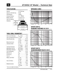
ENCLOSURE<br />
CONSTRUCTION<br />
Please observe the following suggestions<br />
when building an enclosure for GTi<br />
Series subwoofers.<br />
1. Choose an enclosure design from the<br />
Enclosure Design Sheet included with<br />
your subwoofer.<br />
2. Use at least 3/4" (19mm) MDF (medium<br />
density fiberboard) or marine birch<br />
plywood to build the enclosure.<br />
Enclosures for 12" and larger subwoofers<br />
and smaller woofers driven<br />
by high-power amplifiers should be<br />
constructed using 1" (25mm) material.<br />
3. Join pieces of wood with glue and<br />
screws; do not use nails. Once the box<br />
has been tested, seal all joints inside<br />
the box with silicone caulk.<br />
4. Fill the enclosure with damping<br />
material (Dacron, ® fiberglass insulation<br />
or long-fiber wool) according to the<br />
design you have chosen from the<br />
Enclosure Design Sheet. “0% fill”<br />
indicates that no damping material<br />
should be used; “50% fill” indicates<br />
that all interior walls except the baffle<br />
should be lined with 1"-thick damping<br />
material, and “100% fill” indicates that<br />
the box should be loosely stuffed with<br />
damping material.<br />
5. Use PVC or ABS plastic pipe for ports.<br />
Keep in mind that the openings at<br />
either end of the port must be at least<br />
one port diameter away from any<br />
obstruction.<br />
6. Use the 10/24" machine screws and<br />
T-nuts provided to mount the woofer<br />
to the baffle. See Figure 1.<br />
Figure 1. Mounting the GTi woofer in its<br />
enclosure<br />
10/24"<br />
SCREWS<br />
(PROVIDED)<br />
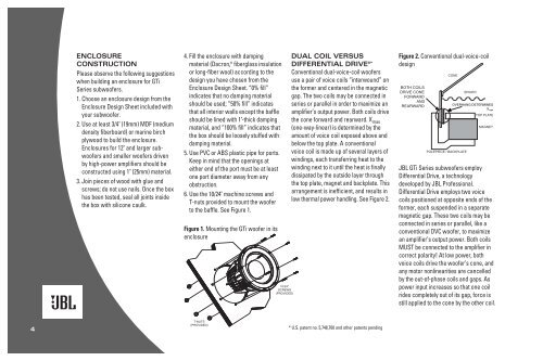
DUAL COIL VERSUS<br />
DIFFERENTIAL DRIVE ® *<br />
Conventional dual-voice-coil woofers<br />
use a pair of voice coils “interwound” on<br />
the former and centered in the magnetic<br />
gap. The two coils may be connected in<br />
series or parallel in order to maximize an<br />
amplifier’s output power. Both coils drive<br />
the cone forward and rearward. X max<br />
(one-way-linear) is determined by the<br />
amount of voice coil exposed above and<br />
below the top plate. A conventional<br />
voice coil is made up of several layers of<br />
windings, each transferring heat to the<br />
winding next to it until the heat is finally<br />
dissipated by the outside layer through<br />
the top plate, magnet and backplate. This<br />
arrangement is inefficient, and results in<br />
low thermal power handling. See Figure 2.<br />
CONVENTIONAL<br />
Figure DUAL 2. Conventional VOICE COIL dual-voice-coil DESIGN<br />
design<br />
BOTH COILS<br />
DRIVE CONE<br />
FORWARD<br />
AND<br />
REARWARD<br />
CONE<br />
POLEPIECE / BACKPLATE<br />
SPIDER<br />
OVERHANG DETERMINES<br />
X max<br />
TOP PLATE<br />
MAGNET<br />
<strong>JBL</strong> GTi Series subwoofers employ<br />
Differential Drive, a technology<br />
developed by <strong>JBL</strong> Professional.<br />
Differential Drive employs two voice<br />
coils positioned at opposite ends of the<br />
former, each suspended in a separate<br />
magnetic gap. These two coils may be<br />
connected in series or parallel, like a<br />
conventional DVC woofer, to maximize<br />
an amplifier’s output power. Both coils<br />
MUST be connected to the amplifier in<br />
correct polarity! At low power, both<br />
voice coils drive the woofer’s cone, and<br />
any motor nonlinearities are cancelled<br />
by the out-of-phase coils and gaps. As<br />
power input increases so that one coil<br />
rides <strong>com</strong>pletely out of its gap, force is<br />
still applied to the cone by the other coil.<br />
4<br />
T-NUTS<br />
(PROVIDED)<br />
* U.S. patent no. 5,748,760 and other patents pending