SB 300 - JBL.com
SB 300 - JBL.com
SB 300 - JBL.com

You also want an ePaper? Increase the reach of your titles
YUMPU automatically turns print PDFs into web optimized ePapers that Google loves.
<strong>SB</strong> <strong>300</strong><br />
<strong>SB</strong><strong>300</strong>CNTR Soundbar + <strong>SB</strong><strong>300</strong>SUB Subwoofer<br />
SERVICE MANUAL<br />
Released 2011<br />
Discontinued XXXX<br />
<strong>JBL</strong> Consumer Products<br />
8500 Balboa Blvd.<br />
Northridge, CA. 91329<br />
Rev1-5/2012
<strong>SB</strong> <strong>300</strong><br />
- CONTENTS -<br />
BASIC SPECIFICATIONS………………………..…….….……………..2<br />
CONTROLS AND CONNECTIONS ..…………..……………………….2<br />
BASIC TROUBLESHOOTING.…………………..……………………….8<br />
SUBWOOFER DETAILED SPECS...….………..………….………..…10<br />
SUBWOOFER EXPLODED VIEW……………....…… ..……… … ….12<br />
SUBWOOFER DISASSEMBLY TIPS..………... ………….…..…….. 13<br />
SUBWOOFER ELECTRICAL PARTS LIST….……….…..……….….14<br />
SUBWOOFER BLOCK DIAGRAM….………………….………………16<br />
SUBWOOFER PCB DRAWINGS…..…….………………………….…17<br />
SUBWOOFER SCHEMATICS………………………..………..…….…21<br />
SOUNDBAR DETAILED SPECS…..…………….…..………………...25<br />
SOUNDBAR EXPLODED VIEW…………..……….…….……………..27<br />
SOUNDBAR ELECTRICAL PARTS LIST..… ...……….…….……..…28<br />
SOUNDBAR BLOCK DIAGRAM.…..….……..…………..………….…30<br />
SOUNDBAR PCB DRAWING…..… ….……………………………..….31<br />
SOUNDBAR SCHEMATICS…..………………………….……………..33<br />
SOUNDBAR CROSSOVER NETWORK…..….….…….……………...35<br />
SOUNDBAR WIRING DIAGRAM……….….…….……..……………...36<br />
SPECIFICATIONS<br />
SYSTEM Frequency response:<br />
<strong>SB</strong><strong>300</strong>CNTR Powered Soundbar<br />
Low-frequency transducer:<br />
High-frequency transducer:<br />
Amplifier power:<br />
Controls (Soundbar or Remote):<br />
Input Connections:<br />
Power requirement:<br />
Power consumption:<br />
Dimensions (H x W x D):<br />
Weight:<br />
<strong>SB</strong><strong>300</strong>SUB Powered Subwoofer<br />
Low-frequency transducer:<br />
Enclosure type:<br />
Amplifier power:<br />
Frequency response:<br />
Audio controls:<br />
Input Connections:<br />
Power requirement:<br />
Power consumption:<br />
Dimensions (H x W x D):<br />
Weight:<br />
42Hz – 20kHz (–3dB)<br />
Two 2" (51mm) cones per channel, shielded<br />
One 1" (25mm) dome per channel, shielded<br />
30 watts per channel<br />
Input Source, Volume, surround mode<br />
Optical digital (TOSLINK) input, stereo analog (RCA-type) inputs<br />
100V – 240V, 50Hz/60Hz, 80W<br />
1W standby; 80W maximum<br />
3-5/8" x 45-3/4" x 3" (92mm x 1162mm x 76mm)<br />
5.5 lb (2.5kg)<br />
8" (203mm) cone, down-firing<br />
Ported (down-firing)<br />
100 watts<br />
42Hz – 200Hz (–3dB)<br />
Level, Phase, Cutoff Frequency<br />
None; wireless from the <strong>SB</strong><strong>300</strong>CNTR Powered Soundbar<br />
100V – 240V, 50Hz/60Hz, 160W<br />
1W standby; 160W maximum<br />
19" x 14-1/4" x 14-1/4"(483mm x 362mm x 362mm)<br />
24.5 lb (11.1kg)<br />
Occasional refinements may be made to existing products without notice but will always meet or exceed original specifications<br />
unless otherwise stated<br />
2
<strong>SB</strong> <strong>300</strong><br />
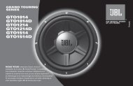
SUBWOOFER REAR-PANEL CONTROLS<br />
Status<br />
LED<br />
Power<br />
Switch<br />
Level<br />
Control<br />
Cutoff<br />
Control<br />
Phase<br />
Switch<br />
Wireless<br />
Pairing Switch<br />
Power Cord<br />
Connector<br />
Status LED: Indicates the subwoofer’s operational status:<br />
• Lights blue continuously when the subwoofer is on and linked to<br />
the soundbar.<br />
• Slowly flashes blue when the subwoofer is on and the wireless link<br />
is not established between the subwoofer and the soundbar.<br />
• Rapidly flashes blue during the wireless pairing process.<br />
• Lights amber continuously when the subwoofer is in the Standby<br />
mode.<br />
• Turns off when the subwoofer’s Power switch is in the “Off”<br />
position.<br />
Level Control: Use this control to balance the subwoofer’s volume<br />
with that of the soundbar. Turn the knob clockwise to increase<br />
the subwoofer’s volume; turn it counterclockwise to decrease the<br />
subwoofer’s volume.<br />
Cutoff Control: This knob adjusts the subwoofer’s cutoff between<br />
40Hz and 200Hz.The higher you set the Cutoff control, the higher<br />
in frequency the subwoofer will operate and the more its bass will<br />
“overlap” that of the soundbar. This adjustment helps achieve a<br />
smooth transition of bass frequencies between the subwoofer and the<br />
soundbar for a variety of different rooms and subwoofer locations. See<br />
Subwoofer Cutoff Control, on page 7, for more information.<br />
Phase Switch: This switch determines whether the subwoofer driver’s<br />
piston-like action moves in and out in phase with the speakers in<br />
the soundbar. If the subwoofer were to play out of phase with the<br />
soundbar speakers, some of the sound waves produced by the<br />
subwoofer or soundbar could be canceled, reducing bass performance<br />
and sonic impact. This phenomenon depends in part on the relative<br />
placement of the speakers in the room. See Subwoofer Phase Switch,<br />
on page 7, for more information.<br />
Wireless Pairing Switch: Press this switch to initiate wireless pairing<br />
between the subwoofer and the soundbar. See Pairing the Units for<br />
Wireless Operation, on page 6, for more information.<br />
Power Switch: Set this switch to the “On” position to activate the<br />
subwoofer. In normal operation, this switch will be left in the “On”<br />
position. See Turning the Subwoofer On and Off, on page 6, for more<br />
information.<br />
If you will not be using the subwoofer for an extended period – for<br />
instance, if you’re going on vacation – set the Power switch to the<br />
“Off” position.<br />
Power Cord Connector: Connect the included power cord here and<br />
into an active, unswitched AC outlet. See Power Connections, on page<br />
5, for more information.<br />
IMPORTANT: Do not connect the power cord to an AC outlet until you<br />
have made and verified all other connections.<br />
3
<strong>SB</strong> <strong>300</strong><br />
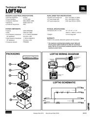
SOUNDBAR REAR-PANEL CONTROLS AND<br />
CONNECTIONS<br />
Press this switch to initiate wireless pairing<br />
between the soundbar and the wireless subwoofer. See Pairing the<br />
Units for Wireless Operation, on page 6, for more information.<br />
Use this switch to adjust the soundbar’s bass for either<br />
wall or table mounting. If you’re mounting the soundbar on a wall with<br />
the included wall-mount brackets, set the EQ switch to the “Wall”<br />
position for the most natural-sounding bass performance. If you are<br />
placing the soundbar on a table, set the EQ switch to the “Table”<br />
position for the most natural-sounding bass performance.<br />
Use the included stereo audio<br />
cable to connect the stereo analog outputs of your TV, DVD player or<br />
cable/satellite tuner here.<br />
If your TV, DVD player or cable/<br />
satellite tuner has an optical digital output, connect it here.<br />
NOTE: You can connect different source <strong>com</strong>ponents to the analog<br />
and digital connections.<br />
Connect the included power cord here. See<br />
Power Connections, on page 5, for more information.<br />
IMPORTANT: Do not connect the power cord to an AC outlet until you<br />
have made and verified all other connections.<br />
Set this switch to the “On” position to activate the<br />
soundbar. In normal operation, this switch will be left in the “On”<br />
position. See Turning the Soundbar On and Off, on page 6, for more<br />
information.<br />
If you will not be using the soundbar for an extended period – for<br />
instance, if you’re going on vacation – set the Power switch to the<br />
“Off” position.<br />
Wireless<br />
Pairing Switch<br />
Analog (AUX) Input<br />
Connections<br />
Power<br />
Switch<br />
EQ Switch Optical Digital Input Connector Power Cord Connector<br />
<br />
<br />
To turn the system on when the soundbar is in the<br />
Standby mode, press the Power button on either the soundbar or<br />
the remote. (The Power indicator will turn blue.) To put the system<br />
in the Standby mode, press either Power button while the system is<br />
on. (The Power indicator will turn amber.) The subwoofer will remain<br />
on for approximately one minute after the soundbar goes into the<br />
Standby mode. If you do not press the Power button, the soundbar<br />
and the subwoofer will both automatically go into the Standby mode<br />
approximately 15 minutes after the audio signal ceases.<br />
NOTE: If you put the soundbar into the Standby mode by pressing<br />
the Power button, you must manually turn it on by pressing the Power<br />
button again. If the system automatically goes into the Standby<br />
mode 15 minutes after the audio signal ceases, it will automatically<br />
turn on whenever the soundbar detects an audio signal at the input<br />
connection that was last used.<br />
Press the Mute button to<br />
mute the <strong>SB</strong><strong>300</strong> system. (The Power indicator flashes blue.) While<br />
the system is muted, press the Mute button again or the Volume Up<br />
button to restore the sound.<br />
NOTE: Momentarily pressing the soundbar’s Power button while the<br />
system is on will mute the system. Momentarily pressing the button<br />
while the system is muted will restore the volume.<br />
Power<br />
Button<br />
Volume Up/<br />
Down Buttons<br />
This button turns the <strong>SB</strong><strong>300</strong> system’s<br />
3-D Surround processing on and off. The Surround Mode indicator<br />
turns blue when 3-D Surround is active, and turns white when 3-D<br />
Surround is not active (normal stereo sound). See Surround Mode<br />
Buttons, on page 6, for more information. NOTE: The remote control<br />
has individual buttons for the Stereo and 3-D Surround modes.<br />
Press the “+” button to increase the<br />
volume; press the “–” button to decrease the volume.<br />
This button switches between the sources<br />
connected to the Source 1 (analog) and Source 2 (digital) inputs.<br />
When Source 1 is active, the Source indicator turns white; when<br />
Source 2 is active, the Source indicator turns blue.<br />
NOTE: The remote control has an individual button for each input<br />
source.<br />
Mute<br />
Buttons<br />
On/Off<br />
Aux<br />
Input<br />
Stereo<br />
Digital<br />
Input<br />
Surround<br />
Mute<br />
Vol.+<br />
Power<br />
Button<br />
Source Selector<br />
Buttons<br />
Vol.–<br />
<br />
Power<br />
Indicator<br />
Surround-Mode<br />
Indicator<br />
4
<strong>SB</strong> <strong>300</strong><br />
CONNECTIONS<br />
<br />
Use the supplied stereo audio cable to connect the<br />
soundbar’s Source 1 (analog) input to your TV’s stereo audio output.<br />
If your TV has two sets of audio output jacks, use the set that has<br />
a fixed (not variable) output level. This will let you turn your TV’s<br />
speakers all the way off while the TV still supplies a constant audio<br />
signal to the soundbar.<br />
If your DVD player, cable tuner or satellite tuner has an optical<br />
digital output, you can use an optical digital audio cable to connect it<br />
to the soundbar’s Source 2 (optical digital) input.<br />
NOTE: If your DVD player, cable tuner or satellite tuner does not have<br />
an optical digital output, you can connect its analog audio output to<br />
your TV. The TV will send its audio signal to the soundbar through the<br />
analog connection described above.<br />
<br />
After verifying that all of the source connections have been made<br />
properly, plug the supplied power cords into the soundbar’s and<br />
subwoofer’s Power Cord connectors, and plug the other ends into<br />
active, unswitched AC outlets. Do NOT plug these cords into the<br />
accessory outlets found on some audio <strong>com</strong>ponents.<br />
<br />
<br />
AUDIO<br />
OUT<br />
Stereo<br />
Audio Cable<br />
(supplied)<br />
Optical Digital<br />
Audio Cable<br />
(not supplied)<br />
Power<br />
Cord<br />
To Unswitched<br />
AC Outlet<br />
<br />
<br />
OPTICAL<br />
DIGITAL<br />
OUT<br />
5
<strong>SB</strong> <strong>300</strong><br />
<br />
<br />
Set the soundbar’s Power switcn to the “On” position.<br />
<br />
After turning the soundbar and subwoofer on for the first time, you<br />
will need to “pair” the subwoofer and soundbar so they both operate<br />
at the same wireless frequency. To pair the units, press the Wireless<br />
Pairing switches on both units within 30 seconds. The units will<br />
<strong>com</strong>municate with each other and operate at the same frequency.<br />
Phase<br />
Press the Power button on either the soundbar or the remote to turn<br />
the soundbar on. To put the soundbar in the Standby mode, press<br />
either Power button while the soundbar is on.<br />
Pa<br />
Power Button<br />
On/Off<br />
Aux<br />
Digital<br />
Power<br />
Button<br />
If you do not press the Power button, the soundbar will automatically<br />
go into the Standby mode approximately 15 minutes after the audio<br />
signal ceases. NOTE: If you have put the soundbar into the Standby<br />
mode by pressing the Power button, you must manually turn it on by<br />
pressing the Power button again. If the soundbar has automatically<br />
gone into the Standby mode 15 minutes after the audio signal has<br />
ceased, it will automatically turn itself on when it receives an audio<br />
signal at either the analog (Aux) input or the optical digital input.<br />
<br />
Set the subwoofer’s Power switch to the “On” position. The<br />
subwoofer will automatically attempt to establish pairing with the<br />
soundbar (the subwoofer’s LED will flash blue). If pairing is not<br />
established within one minute, the subwoofer will enter the Standby<br />
mode (its LED will turn amber). If pairing is established, the subwoofer<br />
will turn on (its LED will light blue continuously).<br />
The subwoofer will remain on for approximately one minute after the<br />
soundbar enters the Standby mode, or for approximately 15 minutes<br />
after the audio signal ceases.<br />
<br />
<br />
NOTE: The maximum wireless operating distance between the<br />
soundbar and subwoofer is approximately 50 feet (15.3m).<br />
<br />
Press the soundbar’s or remote’s Volume Up and Down buttons to<br />
raise and lower the system’s volume one step at a time. Hold down<br />
the buttons to continuously raise or lower the volume.<br />
Mute<br />
Vol.+<br />
Vol.–<br />
Volume Up/Down<br />
Buttons<br />
For the best sound, we re<strong>com</strong>mend turning your TV’s built-in<br />
speakers off. Consult your TV’s owner’s manual to find out how to do<br />
this.<br />
<br />
Momentarily press the soundbar’s Power button or press the remote’s<br />
Mute button to mute the system. (The Power Indicator flashes blue.)<br />
Momentarily press the soundbar’s Power button or press the remote’s<br />
Mute button again to un-mute the system. (The Power Indicator turns<br />
to a steady blue.)<br />
If you will be away from home for an extended period of time, or<br />
if you will not be using the system for an extended period, set the<br />
subwoofer’s Power switch to the “Off” position.<br />
Power<br />
Button<br />
Mute<br />
Button<br />
Mute<br />
Vol.+<br />
Vol.–<br />
<br />
These buttons switch the sound between normal stereo (the Surround<br />
Mode Indicator lights white) and 3-D Surround (the Surround Mode<br />
Indicator lights blue). The 3-D Surround setting will produce a<br />
<strong>com</strong>plete surround-sound experience for anyone sitting in front of and<br />
several feet away from the soundbar. Although it is particularly effective<br />
when watching movies, you can also try the 3-D Surround setting for<br />
music.<br />
Surround-Mode<br />
Button<br />
Surround-<br />
Mode Buttons<br />
Aux<br />
Input<br />
Stereo<br />
Digital<br />
Input<br />
Surround<br />
Vol.+<br />
<br />
6
<strong>SB</strong> <strong>300</strong><br />
<br />
Use the subwoofer’s Level knob to balance the bass with the rest of<br />
the sound. Play music or movies that you are familiar with, and adjust<br />
the subwoofer’s Level knob so the bass sounds balanced on both<br />
music and films. Listen to several different music recordings and film<br />
soundtracks that contain strong bass passages, and find a setting for<br />
the Level knob that doesn’t over-emphasize the bass or make it sound<br />
weak.<br />
Level<br />
MIN<br />
MAX<br />
Once you find a setting for the subwoofer’s Level knob that balances<br />
the bass with the rest of the sound, you shouldn’t have to change it.<br />
<br />
The subwoofer’s Cutoff control adjusts the subwoofer’s cutoff<br />
between 40Hz and 200Hz. The higher you set the Cutoff control, the<br />
higher in frequency the subwoofer will operate and the more its bass<br />
will “overlap” that of the soundbar. This adjustment helps achieve a<br />
smooth transition of bass frequencies between the subwoofer and the<br />
soundbar for a variety of different rooms and subwoofer locations.<br />
Cutoff<br />
40Hz<br />
200Hz<br />
To set the Cutoff control, listen for the smoothness of the bass. If the<br />
bass seems too strong at certain frequencies, try a lower Cutoff control<br />
setting. If the bass seems too weak at certain frequencies, try a higher<br />
Cutoff control setting.<br />
<br />
This switch determines whether the subwoofer’s piston-like action<br />
moves in and out in phase with the speakers in the soundbar.<br />
If the subwoofer were to play out of phase with the soundbar<br />
speakers, some of the sound waves produced by the soundbar and<br />
subwoofer could be canceled out at some frequencies, reducing bass<br />
performance and sonic impact. This phenomenon depends in part on<br />
the relative placement of the soundbar and subwoofer in the room.<br />
Phase<br />
0° 180°<br />
Although there is no absolutely correct setting for the Phase switch, in<br />
most cases it should be left in the “0°” position. When the subwoofer<br />
is properly in phase with the soundbar speakers, the sound will be<br />
clearer and have more impact. It will make percussive sounds like<br />
drums, piano and plucked strings sound more lifelike. The best way<br />
to set the Phase switch is to listen to music that you are familiar with<br />
and adjust the switch so that drums and other percussive sounds have<br />
maximum impact.<br />
7
<strong>SB</strong> <strong>300</strong><br />
<strong>SB</strong>30Troubleshooting<br />
NOTE:Unlesstherearenoindicatorlightspresent,the<strong>SB</strong><strong>300</strong>Subwoofercannotbetestedorevaluatedalone.<br />
Duetoitslackofinputconnections,itreceivesitssignalsolelyandwirelesslyfromthe<strong>SB</strong><strong>300</strong>Soundbar,anda<br />
connectionorsourceproblemwiththeSoundbarcaneasilybemistakenforaproblemwiththeSubwoofer.<br />
Theconnectionandoperationsectioninpreviouspagesshouldbereviewedandfollowedcarefullyfirstbefore<br />
theSubwooferisassumedtobemalfunctioning.TheproceduresbelowassumethatallproperACandsignal<br />
connectionstotheSoundbarhavebeenmade,andallindicatorsontheSoundbarappeartobenormal.<br />
Problem<br />
Solution<br />
<br />
<br />
<br />
<br />
<br />
<br />
<br />
<br />
<br />
<br />
<br />
<br />
<br />
<br />
<br />
<br />
<br />
<br />
<br />
<br />
<br />
<br />
<br />
<br />
<br />
<br />
<br />
<br />
<br />
<br />
<br />
<br />
<br />
<br />
<br />
<br />
<br />
<br />
<br />
<br />
8
<strong>SB</strong> <strong>300</strong><br />
<br />
SECTION:<br />
<br />
<strong>SB</strong><strong>300</strong>SUB<br />
9
<strong>SB</strong> <strong>300</strong><br />
<strong>SB</strong><strong>300</strong> Wireless sub<br />
100W Powered Sub Amp<br />
LINE VOLTAGE Yes/No Hi/Lo Line Nom. Unit Notes<br />
US 120vac/60Hz Yes 108-132 120 Vrms Normal Operation<br />
EU 230vac/50-60Hz Yes 207-253 230 Vrms Normal operation, MOMS required<br />
Parameter Specification Unit<br />
QA Test<br />
Limits Conditions Notes<br />
SYSTEM PERFORMANCE USING LOCAL INPUTS<br />
Amp Section<br />
Type (Class AB, D, other) D n/a n/a<br />
Load Impedance (speaker) 8 Ohms n/a Nominal<br />
Rated Output Power 100 Watts 90<br />
THD @ Rated Power 0.5 % 1 22K filter<br />
THD @ 1 Watt 0.2 % 0.3 22K filter<br />
DC Offset 10 mV-DC 30 @ Speaker Outputs<br />
Damping factor 60 DF 50<br />
Measured at speaker connectors 90% of<br />
rated power<br />
Input Sensitivity local<br />
Input Frequency 50 KHz n/a Nominal Freq. Volume level at maximum<br />
L or R 14 mVrms ±1dB To 1 Watt<br />
System Gain (L or R inputs) 46 dB ±1dB<br />
Signal to Noise<br />
SNR-A-Weighted 67 dBA 62 relative to 1W A-Weighting filter (Volume at max)<br />
SNR-unweighted 53 dBr 50 relative to 1W 22K filter (Volume at max.)<br />
Volume @max, w/ A/P Swept Bandpass<br />
Measurement (Line freq.+ harmonics)<br />
Residual Noise Floor >200Hz 1mV ±1dB (BW=20 KHz) Line level inputs must be terminated using 1KOHM<br />
Residual Noise Floor at 50/60Hz 5mV ±1dB<br />
Volume @max, w/ A/P Swept Bandpass<br />
Measurement (Line freq.+ harmonics)<br />
(BW=20 KHz) Line level inputs must be terminated using 1KOHM<br />
Input Impedance<br />
Line Input (L, R) >10K Ohms n/a Nominal<br />
Power BW<br />
THD+N vs Frequency, 20-20KHz T < 15 Minutes<br />
Power on Delay time 3 sec. 4 AC Power Applied<br />
Efficiency 65 % 60 Test conducted at rated power 30W x 2 Nominal Line voltage<br />
Efficiency at 1/8 of rated power 53 % 50 Test conducted at 5WRMS Nominal Line voltage-Rated impedance 6 Ohms<br />
Standby Input power 0.5 Watts 0.55 Nominal Line voltage RED LED<br />
Idle input power TBD Watts Reference @ nom. line voltage<br />
Maximum allowable input power under nominal Input<br />
voltage and frequency, HOT or COLD operation. LED<br />
GREEN or ORG no signal applied<br />
Power Cons. @ rated power 139 Watts 145 @ nom. line voltage 30 Watts @ 6 Ohms nominal line voltage<br />
Power consumption at 1/4 TBD Watts Reference Output power 10 Watts into 4 Ohms<br />
Power consumption at 1/8 TBD Watts Reference Output power 37 Watts into 4 Ohms<br />
Protections<br />
Short Circuit Protection YES n/a functional Direct short at output<br />
10<br />
Amplifier should resume operation after short circuit<br />
condition removal
<strong>SB</strong> <strong>300</strong><br />
<strong>SB</strong><strong>300</strong> Wireless sub100W Powered Sub Amp (cont'd)<br />
Parameter Specification Unit<br />
QA Test<br />
Limits Conditions Notes<br />
Thermal Protection YES n/a functional<br />
@1/8 max unclipped Power at 1.06 times the<br />
input voltage<br />
DC Offset Protection YES n/a - DC present at Speaker Out leads<br />
External Line Fuse NO n/a - Internal fuse at the power supply section<br />
Temperature rise in accessible metal parts should not<br />
exceed 35K rise for domestic version or 30K rise for<br />
European versions (refer to requirements sheet).<br />
Design must insure no Offset/DC Voltage at the<br />
speaker output under any operating condition<br />
including abnormal operation<br />
Power supply Section<br />
Type SMPS Reference Internal power supply<br />
Rated power 160 Watts Reference<br />
AC input voltage range 100-240 VAC Reference Universal type power supply<br />
AC input frequency 50-60 Hz Reference<br />
AC power cord type IEC60320-1 C7 n/a Reference<br />
Detachable, interchangeable via a 2 Pole<br />
IEC receptacle EN 60320 C7<br />
230V model will include SCHUKO and UK cords,<br />
120V includes 120V US cord only<br />
11
<strong>SB</strong> <strong>300</strong><br />
12
<strong>SB</strong> <strong>300</strong><br />
NOTE if amplifier repair involves the removal of the Control PCB:<br />
after the four Phillips machine screws on the faceplate are removed, three<br />
foam tubes need to be pried away from the faceplate in order to access any<br />
of its <strong>com</strong>ponents with the exception of the wireless module U3. Care<br />
should be taken to do minimal damage to the foam, as these preserve the<br />
air integrity at the openings of the LED and phase & pairing switches. If<br />
these foam tubes are damaged and air is allowed to pass through these<br />
openings upon reassembly, it could affect the performance of the<br />
subwoofer and the escaping air might be audible. Upon reassembly, small<br />
amounts of silicon sealer can be used to assure the foam tubes adhere to<br />
the faceplate as designed.<br />
13
<strong>SB</strong> <strong>300</strong><br />
<br />
<br />
<br />
<br />
<br />
<br />
<br />
<br />
<br />
<br />
<br />
<br />
<br />
<br />
<br />
<br />
<br />
<br />
<br />
<br />
<br />
<br />
<br />
<br />
<br />
<br />
<br />
<br />
<br />
<br />
<br />
<br />
<br />
<br />
<br />
<br />
<br />
<br />
<br />
<br />
<br />
<br />
<br />
<br />
<br />
<br />
<br />
<br />
<br />
<br />
<br />
<br />
<br />
<br />
<br />
<br />
<br />
<br />
<br />
<br />
<br />
<br />
<br />
<br />
<br />
<br />
<br />
<br />
<br />
<br />
<br />
<br />
<br />
<br />
<br />
<br />
<br />
<br />
<br />
<br />
<br />
<br />
<br />
<br />
<br />
<br />
<br />
<br />
<br />
<br />
<br />
<br />
<br />
<br />
<br />
<br />
<br />
<br />
<br />
<br />
<br />
<br />
14
<strong>SB</strong> <strong>300</strong><br />
<br />
<br />
<br />
<br />
<br />
<br />
<br />
<br />
<br />
<br />
<br />
<br />
<br />
<br />
<br />
<br />
<br />
<br />
<br />
<br />
<br />
<br />
<br />
<br />
<br />
<br />
<br />
<br />
<br />
<br />
<br />
<br />
15
<strong>SB</strong> <strong>300</strong><br />
16
<strong>SB</strong> <strong>300</strong><br />
17
<strong>SB</strong> <strong>300</strong><br />
18
<strong>SB</strong> <strong>300</strong><br />
19
<strong>SB</strong> <strong>300</strong><br />
20
1<br />
L<br />
N<br />
!<br />
3.15A/250V<br />
F1<br />
!<br />
MOV1<br />
470V<br />
2.5Ω/5A<br />
NTC1<br />
L1<br />
223/50V<br />
C2<br />
!<br />
L2<br />
65uH<br />
C14<br />
6.8uF/400V<br />
R19<br />
3Ω65<br />
!<br />
CY1<br />
<strong>SB</strong> <strong>300</strong><br />
<strong>SB</strong><strong>300</strong> SUBWOOFER SMPS Power Supply<br />
NOTE: Ordinarily the <strong>JBL</strong> <strong>SB</strong><strong>300</strong> SMPS Power Supply module, part# ETK0926122020, is supplied only as a <strong>com</strong>plete unit. Supplied<br />
Schematic is included only for reference when the above part is not available and/or repair to <strong>com</strong>ponent level is necessary. For <strong>JBL</strong><br />
part number equivalents, contact <strong>JBL</strong> at 516-336-4525.<br />
0.33UF<br />
CX2<br />
R20<br />
3Ω65<br />
!<br />
R14<br />
...Ω<br />
OPEN<br />
R16<br />
10K/NTC<br />
IC2<br />
OB2535<br />
4<br />
3<br />
2<br />
1<br />
5<br />
6<br />
7<br />
8<br />
! !<br />
L3<br />
L4<br />
7.6mH<br />
R4<br />
10K<br />
R6<br />
2M2<br />
C1<br />
222/50V<br />
R17<br />
750K<br />
R18<br />
1M5<br />
R3<br />
3M<br />
!<br />
0.68UF<br />
CX3<br />
R45<br />
2M2<br />
56K<br />
R5<br />
FR107<br />
D1<br />
C15<br />
10uF/50V<br />
15mH<br />
IC1<br />
Q3<br />
AO3400A<br />
R23<br />
47K<br />
R24<br />
6K8<br />
ZD4<br />
24V<br />
1 8<br />
2 7<br />
3 6<br />
4 5<br />
OB2298<br />
ZD5<br />
15V<br />
!<br />
750K<br />
R1<br />
4 BR1<br />
4A/600V<br />
750K<br />
R2<br />
! !<br />
R21<br />
0Ω<br />
224<br />
C26<br />
C4<br />
221/50V *<br />
R44<br />
P6KE200A<br />
D9<br />
FR107<br />
3<br />
103/1KV<br />
120uF/400V *2 222/1KV<br />
2<br />
47K C21<br />
R28<br />
C20A C20 C19 D2<br />
N1/N5 4<br />
1N5408<br />
R52<br />
3<br />
47Ω<br />
C9 OPEN<br />
C8<br />
R12 100p<br />
0Ω R7<br />
47Ω<br />
D4 R42<br />
D3<br />
1Ω1<br />
C17 LL41448 C18 FR107 1<br />
10uF/50V 22uF/50V<br />
N6<br />
LL4148<br />
D8<br />
75 R9<br />
1<br />
N1<br />
2<br />
N3<br />
4<br />
T2<br />
AOTF20N60<br />
R10 ! Q5<br />
33<br />
!<br />
!<br />
N2<br />
1K R11<br />
T2102/100V<br />
C5<br />
9<br />
5 6<br />
D5<br />
<strong>SB</strong>360<br />
C16<br />
100uF/10V<br />
R37<br />
2K4<br />
90V~264V ER39<br />
R25<br />
22Ω<br />
6<br />
C12<br />
100pF/1KV<br />
R29<br />
0.13Ω<br />
R13<br />
10Ω<br />
100<br />
R28<br />
T1<br />
200V<br />
ZD1<br />
OPEN<br />
3.6V<br />
ZD7<br />
a<br />
5<br />
!<br />
T1<br />
R27<br />
1K<br />
222/250V*2<br />
C6 C7 R14<br />
33Ω<br />
D6<br />
MBR30150CT<br />
9<br />
8<br />
N6<br />
12<br />
R15<br />
33Ω<br />
N7<br />
10<br />
C34<br />
223/50V<br />
C24<br />
2200uF/35V<br />
222/250V*2<br />
C11 C10<br />
D7<br />
MBR30150CT<br />
L7<br />
2.2uH<br />
C25<br />
2200uF/35V<br />
C13<br />
102/50V<br />
1000uF/10V<br />
C30<br />
B<br />
4<br />
3<br />
C32<br />
223/50V<br />
On/Off<br />
C22<br />
680uF/35V<br />
L5<br />
1.1uH<br />
L6<br />
1.1uH<br />
C23<br />
680uF/35V<br />
!<br />
IC4<br />
PC-17L1CB<br />
3.3V/1.5A<br />
C27 C31 ZD2<br />
223/50V*2<br />
1<br />
2<br />
ZD8<br />
36V<br />
30V/1W<br />
C28 C33<br />
223/50V*2<br />
2K7<br />
R44<br />
R34<br />
10K<br />
1<br />
2<br />
GND<br />
R30<br />
680<br />
R32<br />
82K<br />
5K6<br />
R33<br />
ZD3<br />
30V/1W<br />
27V<br />
ZD6<br />
R35<br />
100K<br />
R48<br />
10K<br />
1K R49<br />
D11<br />
LL4148<br />
R38<br />
10K<br />
680<br />
R31<br />
C29 473/50V<br />
IC5<br />
3<br />
431 2.5V R36<br />
4K22<br />
-24V<br />
R47<br />
100<br />
ZD9<br />
27V<br />
C36<br />
104<br />
R50<br />
1K<br />
*<br />
10K<br />
R40<br />
Q1<br />
3906<br />
C35<br />
104<br />
3.3V/1.5A<br />
100<br />
R41<br />
*<br />
-24V<br />
+24V<br />
GND<br />
Q4<br />
MMBT3904LT1<br />
a<br />
331<br />
4<br />
!<br />
IC3<br />
1<br />
C3<br />
1000/50V<br />
OPEN<br />
3<br />
2<br />
PC-17L1CB<br />
Q2<br />
MMBT3904LT1<br />
C37<br />
104/1000V<br />
21
<strong>SB</strong> <strong>300</strong><br />
22
<strong>SB</strong> <strong>300</strong><br />
23
<strong>SB</strong> <strong>300</strong><br />
<br />
SECTION:<br />
<br />
<strong>SB</strong><strong>300</strong>CNTR<br />
24
<strong>SB</strong> <strong>300</strong><br />
<strong>SB</strong><strong>300</strong> SoundBar<br />
30W x 2 Soundbar system<br />
LINE VOLTAGE Yes/No Hi/Lo Line Nom. Unit Notes<br />
US 120vac/60Hz Yes 108-132 120 Vrms Normal Operation<br />
EU 230vac/50-60Hz Yes 207-253 230 Vrms Normal operation, MOMS required<br />
Parameter Specification Unit<br />
QA Test<br />
Limits Conditions Notes<br />
SYSTEM PERFORMANCE USING LOCAL INPUTS<br />
Amp Section<br />
Type (Class AB, D, other) D n/a n/a<br />
Load Impedance (speaker) 4 Ohms n/a Nominal<br />
Rated Output Power 30 Watts 28<br />
THD @ Rated Power 0.5 % 1 22K filter<br />
THD @ 1 Watt 0.2 % 0.3 22K filter<br />
DC Offset 12 mV-DC 30<br />
Damping factor 5 DF 5<br />
Measured at speaker connectors<br />
90% of rated power<br />
Input Sensitivity local<br />
Input Frequency 1 KHz n/a Nominal Freq. Volume level at maximum<br />
L or R 53 mVrms ±1dB To 1 Watt<br />
System Gain (L or R inputs) 32 dB ±1dB<br />
Signal to Noise<br />
SNR-A-Weighted 65 dBA 62 relative to 1W A-Weighting filter (Volume at max)<br />
SNR-unweighted 62 dBr 60 relative to 1W 22K filter (Volume at max.)<br />
Volume @max, w/ A/P Swept<br />
Bandpass Measurement (Line<br />
Residual Noise Floor 10K Ohms n/a Nominal<br />
Filters<br />
EQ Modes 2 Table mount and wall mount settings<br />
Power BW<br />
THD+N vs Frequency, 20-<br />
20KHz 55 Volume at maximum<br />
10KHz 60 dB >55 Volume at maximum<br />
Local Input dynamic range<br />
Test frequency 1 KHz<br />
Maximum input voltage without<br />
distorting output signal 2 Vrms functional<br />
With volume level at 1/4 of full scale<br />
increase input level and verify THD<br />
at the output, record the maximum<br />
input level that produces THD<br />
below 1%<br />
Subwoofer output YES Through the wireless Tx<br />
Features --<br />
The purpose of this test is to verify how much voltage<br />
the front end can take before it is overdriven, volume<br />
is set low to prevent the output stage from clipping<br />
Push type buttons to control volume level, and to<br />
scroll through the different surround/effects, source<br />
Front panel controls<br />
selection and power/mute On/Off<br />
DSP processing YES n/a Verify 1 Surround mode, Stereo Modes<br />
Credit card type<br />
remote control unit YES n/a functional<br />
Wireless ready YES n/a functional<br />
Wireless range Tx section >50 ft functional<br />
Volume up and down, surround, bypass, effect mode<br />
and source selection and power On/Off control.<br />
2.4G, Wireless unit must be able to Tx, Subwoofer<br />
signal<br />
Front panel LED Indicator(s) YES n/a functional<br />
System must be provided with LED's indicators,<br />
intended to provide feedback to the end user on<br />
active surround or decoding modes includiing power.<br />
Digital Input YES n/a functional Optical connector<br />
Analog inputs YES n/a functional Stereo RCA Jack (RED-WHT)<br />
Internal power supply YES n/a functional Power supply Class II<br />
25
<strong>SB</strong> <strong>300</strong><br />
Parameter Specification Unit<br />
QA Test<br />
Limits Conditions Notes<br />
Input Configuration<br />
Analog inputs YES -- functional Stereo RCA Jack (RED & WHT)<br />
Digital input YES functional Optical connector<br />
Signal Sensing (ATO)<br />
Auto-Turn-On (yes/no) YES functional<br />
ATO Level L and R inputs, 1KHz 1 mV functional 1KHz Both input signals driven<br />
ATO Turn-on time 5 ms functional<br />
Amp connected and AC on, then<br />
input signal applied<br />
Auto Mute/ Turn-OFF Time 10-15 minutes 8-16<br />
T before muting, after signal is<br />
removed<br />
Auto turn of time (T) must be 5 > T < 15 Minutes<br />
Power on Delay time 3 sec. 4 AC Power Applied<br />
Transients/Pops<br />
ATO Transient 0.5 V-peak 0.5V @ Speaker Output<br />
Amplifier activated by signal presence at the Line<br />
input<br />
Turn-on Transient 0.5 V-peak 0.8V @ Speaker Output AC Line cycled from OFF to ON<br />
Turn-off Transient 0.5 V-peak 0.8V @ Speaker Output AC Line cycled from ON to OFF<br />
Efficiency<br />
Efficiency 65 % 60 Test conducted at rated power 30W xNominal Line voltage<br />
Efficiency at 1/8 of rated power 43 % 40 Test conducted at 5WRMS Nominal Line voltage-Rated impedance 6 Ohms<br />
Standby Input power 0.5 Watts 0.55 Nominal Line voltage RED LED<br />
Maximum allowable input power under nominal Input<br />
voltage and frequency, HOT or COLD operation. LED<br />
Idle input power TBD Watts Reference @ nom. line voltage<br />
GREEN or ORG no signal applied<br />
Power Cons. @ rated power 92 Watts 95 @ nom. line voltage 30 Watts @ 4 Ohms nominal line voltage<br />
Power consumption at 1/4 TBD Watts Reference Output power 7.4 Watts into 4 Ohms<br />
Power consumption at 1/8 TBD Watts Reference Output power 3.7 Watts into 4 Ohms<br />
Protections<br />
Short Circuit Protection YES n/a functional Direct short at output<br />
Amplifier should resume operation after short circuit<br />
condition removal<br />
Thermal Protection YES n/a functional<br />
@1/8 max unclipped Power at 1.06<br />
times the input voltage<br />
DC Offset Protection YES n/a - DC present at Speaker Out leads<br />
Temperature rise in accessible metal parts should not<br />
exceed 35K rise for domestic version or 30K rise for<br />
European versions (refer to requirements sheet).<br />
Design must insure no Offset/DC Voltage at the<br />
speaker output under any operating condition<br />
including abnormal operation<br />
Power supply Section<br />
Type SMPS Reference Internal power supply<br />
Rated power 65 Watts Reference<br />
AC input voltage range 100-240 VAC Reference Universal type power supply<br />
AC input frequency 50-60 Hz Reference<br />
AC power cord type IEC60320-1 C7 n/a Reference<br />
Detachable, interchangeable via a 2<br />
Pole IEC receptacle<br />
EN 60320 C7<br />
230V model will include SCHUKO and UK cords,<br />
120V includes 120V US cord only<br />
IR REMOTE<br />
Range 20 ft >20<br />
Angle 30 deg ± 30 Horizontal and vertical planes Angle is respect to IR receiver location<br />
26
<strong>SB</strong> <strong>300</strong><br />
27
<strong>SB</strong> <strong>300</strong><br />
GGEC P/N<br />
<strong>SB</strong><strong>300</strong>CNTR Bom<br />
Part Name Descriptiong Usage(EA)<br />
designators<br />
LFAWEAVE10100 PCB PCB,FR-4,2,MAIN PCB,1.6mm,62*310mm. 1,0<br />
ERS2C0000ZT0WS Resistor RES-CHIP,0603,1/10W,0 OHM,+0.05 MAX,TAPE,WALSIN 1,0 R68<br />
ERS0301050240S Resistor RES-CHIP,0603,1/10W,1M OHM,5%,WALSIN 1,0 R67<br />
ERS0303340240S Resistor RES,0603,330K OHM,1/10W,+/-5% 1,0 R206<br />
ERS0303920240S Resistor RES-CHIP,0603,1/10W,3.9K OHM,5% 1,0 R508<br />
ERS0305100220S Resistor RES,0603,51 OHM,1/10W,+/-1% 1,0 R336<br />
ERS033206J00 Resistor RES,0603,3.3K OHM,1/10W,+/-5% 2,0 R60,R61<br />
ERS0303330220S Resistor RES,0603 33K OHM 1/10W ±1% PB-FREE 1,0 R208<br />
ERS0304720240S Resistor RES-CHIP,0603,1/10W,4.7K OHM,5%, 4,0 R330,R230,R231,R141<br />
ERS0351110220 Resistor RES,0603,5.11K OHM,1/10W,+/-1% 1,0 R63<br />
ERS05062A0540 Resistor RES,1206,6.2 OHM,1/4W,5% 4,0 R512,R514,R501,R502<br />
ERS2C0203JT0NS Resistor RES-CHIP,0603,1/10W,20K OHM,5% 2,0 R253,R228<br />
ERS047306J00 Resistor RES,0603,47K OHM,1/10W,+/-5% 1,0 R302<br />
ERS0303<strong>300</strong>221S Resistor RES-CHIP,0603,1/10W,33 OHM,1%,NA 9,1<br />
R92,R93,R46,R47,R78,R333,R5<br />
05,R506,R524<br />
ERS2C0470JT0NS Resistor RES-CHIP,0603,1/10W,47 OHM,5%,NA 10,1<br />
R171,R173,R176,R240,R241,R2<br />
42,R227,R211,R136,R504<br />
ERS2C0224JT0NS Resistor RES-CHIP,0603,1/10W,220K OHM,5% 1,0 R225<br />
ERS2C0100JT0NS Resistor RES-CHIP,0603,1/10W,10 OHM,5% 4,0 R500,R510,R511,R525<br />
ERS0301040240S Resistor RES-CHIP,0603,1/10W,100K OHM,5%,Walsin 3,0 R222,R223,R250<br />
ERS0301020240S Resistor RES-CHIP,0603,1/10W,1k OHM,5%,Walsin 7,1<br />
R602,R606,R610,R614,R618,R6<br />
22,R212<br />
ERS0301030240S Resistor RES-CHIP,0603,1/10W,10K OHM,5%,Walsin 38,4<br />
R49,R54,R95,R96,R97,R135,R1<br />
38,R205,R207,R210,R224,R229<br />
,R232,R324,R335,R337,R340,R<br />
349,R352,R353,R354,R355,R36<br />
3,R364,R365,R366,R384,R385,<br />
R129,R132,R134,R130,R251,R6<br />
26,R252<br />
ERS0301010240S Resistor RES-CHIP,0603,1/10W,100 OHM,5% 1,0 R91<br />
ECC0101000620S Capacitor CAP-CER,0603,10P,5%,50V,NPO(COG) 3,0 C205,C206,C546<br />
ECC3022240630S Capacitor CAP-CER,0805,2.2U,10%,25V,X7R 2,0 C137,C136<br />
ECS04741H060 Capacitor CAP-CER,0603,470N,10%,25V,X7R 1,0 C301<br />
ECC3011020633S Capacitor CAP-CER,0603,1N,10%,50V,X7R,WALSIN 6,1<br />
C513,C514,C520,C534,C535,C2<br />
24<br />
ECC3012210632S Capacitor CAP-CER,0603,220P,10%,50V,X7R,WALSIN 3,0 C227,C519,C252<br />
ECC3021020631S Capacitor CAP-CER,0805,1N,10%,50V,X7R 2,0 C515,C540<br />
ECC3011030620S Capacitor CAP-CER,0603,10N,5%,50V,X7R 2,0 C318,C605<br />
ECC3105ZBYT0NS Capacitor CAP-CER,0805,1U,+80/-20%,50V,Y5V,NA 4,0 C222,C359,C505,C524<br />
ECC3011220630S Capacitor CAP-CER,0603,1.2N,10%,50V,X7R 1,0 C521<br />
ECC3011810630 Capacitor CAP-CER,0603,180P,10%,50V,X7R 2,0 C140,C141<br />
ECC3011040631S Capacitor CAP-CER,0603,100N,10%,50V,X7R 30,3<br />
C225,C143,C201,C226,C229,C2<br />
31,C232,C<strong>300</strong>,C312,C321,C323<br />
,C324,C332,C333,C500,C831,C<br />
504,C525,C604,C319,C322,C20<br />
4,C261,C262,C263,C260,C91,C<br />
5,C328,C93<br />
ECC2470JBCT0NS Capacitor CAP-CER,0603,47P,5%,50V,NPO(COG),TAPE,NA, 3,0 C543,C544,C545<br />
ECC3021040630S Capacitor CAP-CER,0805,100N,10%,50V,X7R 16,2<br />
C522,C523,C800,C819,C824,C5<br />
01,C502,C503,C508,C509,C510<br />
,C511,C528,C529,C530,C531<br />
ECC1016810620S Capacitor CAP-CER,0603,680P,5%,50V,NPO(COG) 4,0 C507,C526,C527,C547<br />
ECC0011010620S Capacitor CAP-CER,0603,100P,5%,50V,NPO(COG) 6,1<br />
C132,C134,C518,C228,C208,C2<br />
09<br />
ECC0013<strong>300</strong>620S Capacitor CAP-CER,0603,33P,5%,50V,NPO(COG),SAMSUNG 1,0 C92<br />
ECC0012200620S Capacitor CAP-CER,0603,22P,5%,50V,NPO(COG),SAMSUNG 4,0 C329,C330,C202,C203<br />
ECC0013310630 Capacitor CAP-CER,0603,330P,10%,50V,X7R 1,0 C264<br />
ECC1011010930S Capacitor CAP-CER,0603,100P,5%,100V,NPO(COG),SAMSUNG 1,0 C603<br />
ECE6071000351S ELECT Capacitor 10uF/16V,20%,85, SIZE C(D*H=5*5.4),brand:Panasoic EEE1CA100NR 3,0 C223,C233,C250<br />
ENB1046010010 Bead BEAD,600 OHM@100MHZ,0.5A,0805 3,0 L100,L<strong>300</strong>,FB803<br />
ENB1036010040S Bead FERRITE,0603,600 OHM,100MHZ,200mA 7,1<br />
R<strong>300</strong>,R325,R326,R327,R521,R5<br />
22,R523<br />
ENB1046010030S Bead FERRITE BEAD 0805, 600 OHM AT 100MHZ, 0.3 OHM DCR, 500MA DC(brand:3 5,1 L1,L500,L504,L505,L507<br />
EDAA4148W0000S Diode DIODES,SM,SOD123,1N4148W,brand:Panjit 5,1 D301,D202,D203,D204,D205<br />
EIQLM11171800 IC LM1117,VOLT REG,LDO,1.8V OUT,800MA,SOT-223SPX1117M3-L-1.8 1,0 IC801<br />
EIQLM11173<strong>300</strong> IC LM1117,VOLT REG,LDO,3.3V OUT,800MA,SOT-223SPX1117M3-L-3.3 2,0 IC800,IC802<br />
EI020SGM809T0S IC IC,SGM809,SOT23-3,brand:SG,modle:SGM809-TXN3L(3.08V) 1,0 IC501<br />
EICCJ78M05X0 IC CJ78M05 TO-252 1,0 IC107<br />
EI05NJU718100S IC IC,8PIN,NJU7181,Package,TVSP8 1,0 IC202<br />
EILS25VF08010S IC IC,SOIC8,SST25VF080B DIG FLASH 8Mbit 66MHz 1,0<br />
U13(SMT,:<strong>SB</strong><strong>300</strong>,<br />
DSP,PP,8M,3.001.bin)<br />
EI010STA32610 IC STA326,PowerSO36 1,0 U500<br />
EICSTM8S20700S IC IC,QFP-48,STM8S207C8T6 1,0 IC302<br />
EIP00CS841610 IC CS8416,TSOP28 CS8416-CZZ 1,0 IC<strong>300</strong><br />
EICCS49531400S IC IC,CS495314-CVZR1,Package,128PIN LQFP,brand:CLRRUS LOGIC 1,0 U1<br />
EIP00CS534310 IC CS5343,TSSOP10 CS5343-CZZ 1,0 IC104<br />
EIMNJM2100V00S IC IC,NJM2100V,OP,SSOP-8 1,0 IC201<br />
EAMMBT222200 transistor NPN,SOT-23,MMBT2222,600mA,VCEO=30V,<strong>300</strong>mW,REEL,NA 2,0 Q201,Q202<br />
EI23NJM256200S IC IC,NJM2562,VIDEO,buffer MTP6 1,0 IC203<br />
ERS082206J00 Resistor RES,0603,8.2K OHM,1/10W,+/-5% 2,0 R221,R220<br />
ECC1012700620S Capacitor CAP-CER,0603,27P,5%,50V,NPO(COG) 2,0 C33,C8<br />
ECCB04T474AKES Capacitor CAP-CER,0805,470N,10%,25V,X7R,TDK:C2012X7R1E474K 3,0 C220,C221,C253<br />
ECE0091010354S Capacitor . 4,0 C325,C314,C327,C138<br />
ECE01061CM00 Capacitor 10uF/16V ,20% foot distance+5mm=,4*7 3,0 C1,C145,C147<br />
ECE04761CM02S Capacitor E-CAP,47UF/16V,±20%,105 1,0 C516<br />
ECM1086840650S ELECT Capacitor red,foot distance=5mm,0.68UF,50V,10% 2,0 C512,C532<br />
ECE4231010354S ELECT Capacitor . 10,1<br />
C845,C187,C833,C841,C843,C8<br />
29,C821,C188,C828,C365<br />
ECE4241000354S ELECT Capacitor . 3,0 C7,C3,C9<br />
ERS0301050240S Resistor RES-CHIP,0603,1/10W,1M OHM,5%,WALSIN 1,0 R367<br />
ECS21501H06J Capacitor CAP-CER,0603,15P,5%,50V,NPO(COG) 1,0 C23<br />
ERS2C0100JT0NS Resistor RES-CHIP,0603,1/10W,10 OHM,5% 2,0 R625,R393<br />
ERS0303<strong>300</strong>221S Resistor RES-CHIP,0603,1/10W,33 OHM,1%,NA 1,0 R509<br />
ERS07500603J Resistor RES,0603,75 OHM,1/10W,+/-5% 1,0 R83<br />
ERS0301030240S Resistor RES-CHIP,0603,1/10W,10K OHM,5%,Walsin 10,1<br />
R50,R51,R334,R379,R380,R381<br />
,R382,R383,R386,R392<br />
28
<strong>SB</strong> <strong>300</strong><br />
<br />
<br />
<br />
<br />
<br />
<br />
<br />
<br />
<br />
<br />
<br />
<br />
<br />
<br />
<br />
<br />
<br />
<br />
<br />
<br />
<br />
<br />
<br />
<br />
<br />
<br />
<br />
<br />
<br />
<br />
<br />
<br />
<br />
<br />
<br />
<br />
<br />
<br />
<br />
<br />
<br />
<br />
<br />
<br />
<br />
<br />
<br />
<br />
<br />
<br />
<br />
<br />
<br />
<br />
<br />
<br />
<br />
<br />
<br />
<br />
<br />
<br />
<br />
<br />
<br />
<br />
<br />
<br />
<br />
<br />
<br />
<br />
<br />
<br />
<br />
<br />
<br />
<br />
<br />
<br />
<br />
<br />
<br />
<br />
<br />
29
<strong>SB</strong> <strong>300</strong><br />
MCLK<br />
AUX IN<br />
RCA<br />
AUX Audio Input<br />
Optical input<br />
SPDIF-IN<br />
L<br />
R<br />
AUDIO A/DC<br />
Converter<br />
CS5343<br />
DIGITAL AUDIO<br />
Interface Receiver<br />
IC CS8416<br />
MCLK<br />
LRCK<br />
SCLK<br />
D/SD1<br />
D/SD0<br />
D S P<br />
C S 495314<br />
Dolby/DTS DECODE<br />
UPMIXING Matrix<br />
SUB Volume Control<br />
Virtual Surround Post-Processing<br />
Bass Management System<br />
DA/LRCK<br />
DA/SCLK<br />
DA/SD0<br />
I2S<br />
STA326<br />
POWER AMP<br />
L_CH<br />
R_CH<br />
4 Ohm<br />
8 Ohm<br />
8 Ohm<br />
4 Ohm<br />
8 Ohm<br />
8 Ohm<br />
I2C BUS<br />
SPI Flash<br />
32K<br />
SST25VF080B<br />
SPI<br />
IA2E Wireless<br />
transmitter<br />
+VDD<br />
+VCC<br />
subwoofer<br />
POWER SUPPLY<br />
+20V<br />
TRANSFORMER<br />
LED Temp (5 LED)<br />
5 KEY<br />
KEY CONN SYSTEM<br />
M C U<br />
STM8S207C8T6<br />
+5VD<br />
SDAND-BY<br />
+5V<br />
MOSFET<br />
MOSFET<br />
MOSFET<br />
BRIDGE<br />
REGULATOR<br />
S1<br />
AC-SW<br />
IC ---<br />
IC ----<br />
+5V<br />
AMC1117<br />
+3.3V OUT<br />
AC 100V~240V 50Hz/60Hz<br />
AC Input<br />
AMC1117<br />
+1.8V OUT<br />
<strong>SB</strong><strong>300</strong> System Block DIAGRAM<br />
30<br />
VER:1.0<br />
Zou WanYong
<strong>SB</strong> <strong>300</strong><br />
<br />
31
<strong>SB</strong> <strong>300</strong><br />
32
1<br />
3<br />
<strong>SB</strong> <strong>300</strong><br />
<strong>SB</strong><strong>300</strong> SOUNDBAR SMPS Power Supply<br />
NOTE: Ordinarily the <strong>JBL</strong> <strong>SB</strong><strong>300</strong> SMPS Power Supply module, part# ETK0926122030, is supplied only as a <strong>com</strong>plete unit. Supplied<br />
Schematic is included only for reference when the above part is not available and/or repair to <strong>com</strong>ponent level is necessary. For <strong>JBL</strong><br />
part number equivalents, contact <strong>JBL</strong> at 516-336-4525.<br />
L<br />
N<br />
F1<br />
250V3.15A<br />
MOV1<br />
10471<br />
NTC1<br />
2.2M 1206 2.2M 1206<br />
R1 R3<br />
R2<br />
R4<br />
2.2M 1206 2.2M 1206<br />
R18<br />
15.4K<br />
CX1 0.33uF<br />
L1<br />
L2<br />
IC1<br />
1 8<br />
2 7<br />
3 6<br />
4 5<br />
OB2201<br />
R19<br />
100K NTC<br />
4<br />
C7<br />
220pF<br />
R5 <strong>300</strong>K<br />
DB1<br />
R6 <strong>300</strong>K<br />
C1 120uF/400V R8 <strong>300</strong>K<br />
2<br />
R7 <strong>300</strong>K<br />
2A600V<br />
ZD1<br />
12V<br />
D3<br />
1N4148 R11<br />
1K<br />
R12<br />
10R R10 150R<br />
R13<br />
560R<br />
C8<br />
1uF<br />
C2 103 1KV<br />
D4 1N4148<br />
Q1<br />
7N65<br />
R14<br />
100K<br />
B2<br />
D1<br />
2A800V<br />
B1<br />
R21<br />
0.2R<br />
C9<br />
NC<br />
T1<br />
C3<br />
12<br />
103 1KV<br />
R15<br />
30K<br />
R20<br />
15K<br />
10<br />
7<br />
9<br />
PQ-2620<br />
R9<br />
33<br />
1000pF<br />
D2<br />
6<br />
3<br />
20100<br />
C6<br />
C4<br />
1000uF 25V<br />
C10<br />
2200p<br />
IC2<br />
3<br />
4<br />
L4<br />
3.5*10<br />
C5<br />
1000uF 25V<br />
1<br />
2<br />
C12<br />
680uF 25V<br />
R22<br />
560R<br />
R23<br />
2K<br />
IC5<br />
TL431<br />
R17<br />
1K<br />
C14<br />
0.01<br />
R24<br />
32.4K<br />
R25<br />
4.32K<br />
L3<br />
R16<br />
4.7K 0805<br />
C15<br />
JUMP<br />
C13<br />
NC<br />
+21V<br />
AGND<br />
C19<br />
4.7uF 400V<br />
R37 180K<br />
R38 180K<br />
CY1 222/250V<br />
C11<br />
103 1KV<br />
C16<br />
10uF/50V<br />
C21<br />
104<br />
Q2<br />
MMBT4403<br />
R26<br />
20K<br />
R56<br />
20K<br />
R28<br />
1M<br />
R29<br />
1M<br />
ZD2<br />
4.7V<br />
C17<br />
10uF/50V<br />
C18<br />
4.7uF/50V<br />
R30<br />
1K<br />
C20<br />
104<br />
R36<br />
2.2R<br />
D5<br />
FR107<br />
IC6<br />
1 8<br />
2 7<br />
3 6<br />
4 5<br />
OB2358L DIP-8<br />
R42 2.49R<br />
R43 2.74R<br />
C30<br />
R44 NC 0.01<br />
C25<br />
2200pF250V<br />
R57<br />
100<br />
T2<br />
5 7<br />
D6<br />
1N4007<br />
ZD3<br />
10V<br />
J6<br />
47.R<br />
4<br />
1<br />
R39<br />
47R<br />
C26 102/100V<br />
D10 <strong>SB</strong>540<br />
3.5*10<br />
C27<br />
1000uF/10V<br />
10<br />
D9<br />
8<br />
2100<br />
C31<br />
470uF/16V<br />
2 9<br />
EF20 8PIN<br />
3<br />
IC3<br />
1<br />
4<br />
IC4 3<br />
2<br />
1<br />
L7<br />
3.5*10<br />
C32<br />
100uF16V<br />
L5<br />
R40<br />
C22<br />
NC NC<br />
C28<br />
470uF/10V<br />
R41<br />
NC<br />
R45<br />
150R<br />
R31<br />
2K<br />
R32<br />
10K<br />
IC7<br />
TL431<br />
R51<br />
62K<br />
C23<br />
224<br />
R52 4.75K<br />
R33<br />
3.9K<br />
Q3<br />
A04406<br />
R34<br />
10K<br />
C29 R47<br />
10uF50V 10K<br />
R46<br />
1K D7<br />
Q4<br />
2<strong>SB</strong>772 JUMP<br />
R50<br />
10K<br />
R53<br />
2K<br />
Q5<br />
4401<br />
C24<br />
104<br />
R48<br />
NC<br />
D8<br />
R35<br />
R54 3K<br />
2K<br />
JUMP<br />
R49<br />
NC<br />
R55<br />
NC<br />
R27<br />
NC<br />
BK 5V0.5A<br />
+5V1.2A<br />
+9V0.5A<br />
ON-OFF<br />
GND<br />
4<br />
2<br />
33
3<br />
1<br />
2<br />
1<br />
1<br />
1<br />
2<br />
8<br />
1<br />
2<br />
3<br />
4<br />
DA/SCLK<br />
DA/LRCK<br />
DA/SD0<br />
AMP_RST<br />
AMP_I2C SDA<br />
AMP_I2C SCL<br />
1<br />
MCLK<br />
A<br />
<strong>SB</strong> <strong>300</strong><br />
+3.3VD<br />
D<br />
C<br />
B<br />
A<br />
C368<br />
104<br />
+3.3V<br />
LED KEY - PCB Board<br />
Rear I/O - PCB Board<br />
R204 270<br />
SW101A<br />
EQ_Wall<br />
TA201<br />
Pairing<br />
FB101<br />
600<br />
L<br />
JK101A<br />
AUX IN<br />
FB100<br />
600<br />
R<br />
JK101B<br />
AUX IN<br />
FB<strong>300</strong><br />
JK102<br />
10nH<br />
1 DI<br />
2<br />
3<br />
Optical In<br />
+3.3VC<br />
L<strong>300</strong><br />
L301<br />
10uH<br />
600<br />
C367<br />
104<br />
CN805<br />
1 +PVCC<br />
2 GND<br />
POWER<br />
CN807<br />
+5V<br />
From Main PCB<br />
From Main PCB<br />
RB<strong>300</strong><br />
CN8/20<br />
RB301<br />
SPDIF_IN<br />
6<br />
5<br />
4<br />
3<br />
2<br />
1<br />
C819<br />
104<br />
C312 104<br />
C314<br />
100U/10V<br />
AUX FREQ:<br />
MCLK: 12.288M<br />
LRCK: 48K<br />
SLCK:3.07M<br />
FB801<br />
220 (100MHz)<br />
C821<br />
100U/16V<br />
1<br />
2<br />
3<br />
4<br />
5<br />
6<br />
CN6/20_L<br />
1<br />
2<br />
3<br />
4<br />
5<br />
6<br />
7<br />
8<br />
C822<br />
104<br />
+5V<br />
GND<br />
BK5V<br />
POWER_ON/OFF<br />
C824<br />
104<br />
R322<br />
C318 103<br />
C315<br />
3K<br />
0.022uF<br />
C320 102<br />
3 IC800 2<br />
GJ1117A-3.3<br />
C826 104<br />
FB601 600 LED_6A<br />
FB602 600 LED_5A<br />
FB603 0 R LED_4A<br />
FB604 600 LED_3A<br />
FB605 600 LED_2A<br />
FB606 600 LED_1A<br />
FB609 600 I/O_KEY5<br />
FB610 600 I/O_KEY4<br />
FB611 600 I/O_KEY3<br />
FB612 600 I/O_KEY2<br />
FB613 600 I/O_KEY1<br />
C122 100P<br />
C319<br />
104<br />
22V<br />
C123 100P<br />
BK5V<br />
C800<br />
104<br />
C829<br />
100U/16V<br />
C364<br />
100P<br />
COAX IN<br />
D201<br />
Blue<br />
Pairing<br />
C102<br />
104 C101<br />
ESD1<br />
10U/16V<br />
TVS_SMT<br />
R101 47<br />
R393 10<br />
C<strong>300</strong> 104<br />
C321 104<br />
C322 104<br />
8416 REST<br />
C828<br />
100U/16V<br />
C831 104<br />
C832 104<br />
+PVCC<br />
LED_1A<br />
LED_2A<br />
LED_3A<br />
LED_4A<br />
LED_5A<br />
LED_6A<br />
1<br />
2<br />
3<br />
4<br />
5<br />
6<br />
7<br />
8<br />
9<br />
10<br />
11<br />
12<br />
13<br />
14<br />
9<br />
8<br />
7<br />
6<br />
5<br />
4<br />
3<br />
2<br />
1<br />
BK5V-A<br />
+9V<br />
+3.3VD<br />
RXP3<br />
RXP2<br />
RXP1<br />
RXP0<br />
RXN<br />
VA<br />
AGND<br />
FILT<br />
TA601<br />
IC<strong>300</strong><br />
CS8416<br />
REST<br />
RXP4<br />
RXP5<br />
RXP6SDA/CDOUT<br />
RXP7<br />
LD602<br />
LD603<br />
RB101 CN101<br />
CN9/20<br />
+5V<br />
+5V<br />
C365<br />
100U/16V<br />
CN9/20<br />
OLRCK<br />
OSCLK<br />
SDOUT<br />
OMCK<br />
RMCK<br />
VD<br />
DGND<br />
VL<br />
GPO0<br />
GPO1<br />
AD2/GPO2<br />
SCL/CCLK<br />
AD0/CSAD1/CDIN<br />
Source<br />
TA602 Volume -<br />
TA603 Volume +<br />
TA604<br />
LD601<br />
LD605<br />
TA605<br />
LD604<br />
LD606<br />
White<br />
Blue<br />
Surround<br />
White<br />
Blue<br />
Power<br />
Blue<br />
Amber<br />
9<br />
8<br />
7<br />
6<br />
5<br />
4<br />
3<br />
2<br />
1<br />
+9V<br />
L-IN<br />
R_IN<br />
2.4G_Pairing<br />
LED_2.4G<br />
EQ_Wall<br />
BK5V-A<br />
SPDIF_IN<br />
28<br />
27<br />
26<br />
25<br />
24<br />
23<br />
22<br />
21<br />
20<br />
19<br />
18<br />
17<br />
16<br />
15<br />
C189<br />
104<br />
L803<br />
10uH<br />
C843<br />
100U/16V<br />
C833<br />
100U/16V<br />
+5V<br />
+3.3VC<br />
R302<br />
47K<br />
R324<br />
10K<br />
R129<br />
R130 10K<br />
DAVCC<br />
10K<br />
R132<br />
10K<br />
R134<br />
10K<br />
PULL-UP SELECT<br />
CONTROL PORT MODE<br />
R<strong>300</strong> (FB 600)<br />
R327 (FB 600)<br />
R325 (FB 600)<br />
R326 (FB 600)<br />
I2C SDA<br />
I2C SCL<br />
L802<br />
10UH<br />
3 IC801<br />
GJ1117A-1.8<br />
C836 104<br />
1<br />
C188<br />
100U/16V<br />
IC107<br />
7805<br />
C323<br />
104<br />
IN OUT<br />
3 IC802 2<br />
GJ1117A-3.3<br />
C844 104<br />
C845<br />
100U/16V<br />
2<br />
C841<br />
100U/16V<br />
C324 104<br />
C132<br />
100P C136<br />
225<br />
C134<br />
100P<br />
+3.3VC<br />
3<br />
8416 SDOUT<br />
XTAL_OUT<br />
MCLK<br />
C140<br />
180P<br />
C186<br />
104<br />
C141<br />
180P<br />
S/PDIF-CS8416<br />
C842 104<br />
LRCK<br />
SCLK<br />
TP312<br />
TEST<br />
TP313<br />
TEST<br />
C187<br />
100U/16V<br />
C846 104<br />
L100<br />
10UH<br />
C138<br />
100U/10V<br />
C137<br />
225<br />
C325<br />
100U/10V<br />
C207<br />
C208<br />
NC-22P<br />
100P<br />
FB802<br />
100UH<br />
C847 1000U/10V<br />
C143<br />
104<br />
C145<br />
10U/16V<br />
C209<br />
100P<br />
DAVCC<br />
+3.3VB<br />
+3.3V<br />
FB803<br />
+DSP_1.8VD<br />
220 (100MHz)<br />
10<br />
9<br />
8<br />
7<br />
6<br />
C146 104<br />
FW TEST<br />
TO LED PCB<br />
TO KEY PCB<br />
VA<br />
GND<br />
AINR<br />
VQ<br />
IC104<br />
CS5343<br />
AINL<br />
L-IN<br />
SPDIF_IN<br />
FW upgrade<br />
LED_1<br />
LED_2<br />
LED_3<br />
R_IN<br />
LED_4<br />
LED_5<br />
LED_6<br />
SDOUT<br />
SCLK<br />
LRCK<br />
MCLK<br />
FILT+<br />
CN302<br />
4<br />
3 SWIM<br />
2<br />
1 REST<br />
CN4/25<br />
CN<strong>300</strong><br />
8<br />
7<br />
6<br />
5<br />
4<br />
3<br />
2<br />
1<br />
CN8/20<br />
CN301<br />
CN6/20<br />
A/D - CS5343<br />
PULL-UP MASTER MODE<br />
PULL-DOWN SLAVE MODE<br />
1<br />
2<br />
3<br />
4<br />
5<br />
C147<br />
10U/16V<br />
R173 47<br />
R176<br />
47<br />
C148 104<br />
R135<br />
10K<br />
R221<br />
C221 474 8K2<br />
C220 474 R220 8K2 6<br />
2.5VDD R253 5<br />
20K C264<br />
330P<br />
C226 104 R229 10K<br />
CN303<br />
4<br />
3 RXD<br />
2 TXD<br />
1<br />
CN4/25<br />
R602<br />
1K<br />
R606<br />
1K<br />
R610<br />
1K<br />
R614<br />
1K<br />
R618<br />
1K<br />
R622<br />
1K<br />
6<br />
5<br />
4<br />
3<br />
2<br />
1<br />
LED_1A<br />
LED_2A<br />
LED_3A<br />
LED_6A<br />
LED_5A<br />
LED_4A<br />
LED_3A<br />
LED_2A<br />
LED_1A<br />
I/O_KEY5<br />
I/O_KEY4<br />
I/O_KEY3<br />
I/O_KEY2<br />
I/O_KEY1<br />
CN201<br />
CN5/20<br />
IR<br />
4<br />
5<br />
6<br />
C232<br />
104<br />
LED_4A<br />
LED_5A<br />
LED_6A<br />
R138<br />
10K<br />
-<br />
+<br />
1<br />
2<br />
3<br />
4<br />
5<br />
C603 100P<br />
B+<br />
R136 47<br />
R141<br />
4.7k<br />
C252 220P<br />
R252 10K<br />
I2C SCL_1<br />
I2C SDA_1<br />
2.4G_REST<br />
MON_Tx<br />
R626<br />
10K<br />
CS5343 SDOUT1<br />
R171<br />
47<br />
C206<br />
10P<br />
BK5V<br />
SN601<br />
IR SENSOR<br />
SCLK<br />
LRCK<br />
MCLK<br />
7<br />
C253 474<br />
IC201B<br />
NJM2100V<br />
BK5V-A<br />
C230<br />
BK5V-A<br />
104<br />
C326 104<br />
R367<br />
XL303<br />
11.0592M<br />
C329<br />
22P<br />
IR<br />
C604 104<br />
C605 103<br />
IC203<br />
NJM2562 C231 104<br />
3<br />
Vin Vsag<br />
2 C229 104<br />
GND V_OUT<br />
1<br />
VCC Power Save<br />
R208<br />
R232<br />
33K<br />
10K<br />
BK5V-A<br />
C327<br />
100U/10V<br />
R333<br />
33<br />
R330<br />
4K7<br />
C328 104<br />
1M<br />
C333<br />
104<br />
R625<br />
10<br />
R230<br />
4K7<br />
R231<br />
4K7<br />
D202<br />
1N4148<br />
C330<br />
22P<br />
D203<br />
1N4148<br />
C223<br />
10U/16V<br />
D301<br />
1N4148<br />
IR<br />
+3.3VB<br />
MCLK<br />
BK5V-A<br />
R212<br />
2.5VDD<br />
+3.3VD<br />
REST<br />
R336 51<br />
RXD<br />
TXD<br />
R201<br />
NC<br />
C204<br />
104P<br />
SPI_FLASH_CS<br />
SPI_FLASH_MISO<br />
R222<br />
100K<br />
IC302<br />
STM8S207C8T6<br />
C301<br />
0.47uF<br />
2.4G_REST<br />
C201<br />
104<br />
R228<br />
20K<br />
C233<br />
SMT_10U/16V<br />
R210<br />
1K<br />
10K<br />
C366<br />
104<br />
R96<br />
10K<br />
1<br />
2<br />
3<br />
4<br />
5<br />
6<br />
7<br />
8<br />
9<br />
10<br />
11<br />
12<br />
BK5V<br />
R98<br />
NC<br />
C334<br />
104<br />
48<br />
NRST<br />
R95<br />
10K<br />
+3.3VD<br />
SPI_FLASH_CS<br />
SPI_FLASH_MISO<br />
PD7<br />
OSCIN<br />
OSCOUT<br />
Vssio_1<br />
Vss<br />
VCAP<br />
Vdd<br />
Addio_1<br />
PA3<br />
47<br />
PD6/UART3_RX<br />
46<br />
PA4/UART1_RX<br />
PA5/UART1_TX<br />
PA6<br />
C205<br />
10P<br />
R386 10K<br />
Vdda<br />
13<br />
BK5V<br />
LED_2.4G<br />
C261<br />
104<br />
Q201<br />
PMBT2222<br />
2.4G_Pairing<br />
C227 220P<br />
R206 330K<br />
IC201A<br />
2 NJM2100V<br />
-<br />
1<br />
3<br />
+<br />
B-<br />
R385 10K<br />
Vssa<br />
14<br />
C262<br />
104<br />
R211<br />
47<br />
R384 10K<br />
PD5/UART3_TX<br />
PB7<br />
15<br />
MON_Tx<br />
R337 10K<br />
45<br />
PD4<br />
PB6<br />
16<br />
I/O_KEY5<br />
I/O_KEY4<br />
<br />
R335 10K<br />
44<br />
PD3<br />
PB5<br />
17<br />
I/O_KEY3<br />
U13<br />
SST25VF080B<br />
1<br />
CE VDD<br />
2<br />
SO HOLD<br />
3<br />
WP SCK<br />
4<br />
VSS SI<br />
R334 10K<br />
EQ_Wall<br />
2.4G_INT<br />
DSP_CS<br />
SCP_CLK<br />
SCP_MOSI<br />
SCP_MISO/SDA<br />
R383<br />
10K<br />
R382<br />
10K<br />
1<br />
2<br />
3<br />
4<br />
5<br />
6<br />
7<br />
8<br />
9<br />
10<br />
R381<br />
10K<br />
U201<br />
BLUE_2.4G_LCOS82<br />
43<br />
PD2<br />
PB4<br />
18<br />
I/O_KEY2<br />
Vcc<br />
GND<br />
MCLK<br />
GPIO20<br />
GPIO8<br />
GPIO12<br />
GPIO17<br />
GPIO13<br />
PD_OUT<br />
GPIO15<br />
C222 105<br />
R380<br />
10K<br />
R365 10K<br />
SWIM<br />
42<br />
PD1<br />
PB3<br />
19<br />
I/O_KEY1<br />
R379<br />
10K<br />
I2C_SCL_MST<br />
11<br />
41<br />
PD0<br />
PB2<br />
20<br />
LED_1<br />
I2C_SDA_MST<br />
12<br />
40<br />
PE0/CLK_CCO<br />
PB1<br />
21<br />
LED_2<br />
GPIO16_TXD<br />
13<br />
TP201<br />
TEST<br />
J103<br />
1 2<br />
3 4<br />
5 6<br />
7 8<br />
CN_DIP_2.54_2X4P_H<br />
(TEST PORT)<br />
D204<br />
1N4148<br />
Digital Signal Detect<br />
8<br />
7<br />
6<br />
5<br />
R363 10K<br />
DSP_IRQ<br />
39<br />
PE1/I2C_SCK<br />
PB0<br />
22<br />
Anolog Signal Detect<br />
GPIO14<br />
14<br />
2.4G_INT<br />
+3.3VD<br />
R364<br />
10K<br />
DSP_BSY<br />
38<br />
PE2/I2C_SDA<br />
PE7<br />
23<br />
SPI_FLASH_CLK<br />
SPI_FLASH_MOSI<br />
C91<br />
0.1uF<br />
R366<br />
10K<br />
DSP RESET<br />
37<br />
PE3<br />
PE6<br />
24<br />
C332<br />
104<br />
PG1<br />
PG0<br />
PC7/SPI_MISO<br />
PC6/SPI_MOSI<br />
Vddio_2<br />
Vssio_2<br />
PC5/SPI_SCK<br />
LED_3<br />
GPIO21_WP<br />
15<br />
I2C_SDA_SLV<br />
I2C_SCL_SLV<br />
PC4<br />
PC3<br />
PC2<br />
PC1<br />
PE5/SPI_NSS<br />
LED_4<br />
NC<br />
16<br />
R226<br />
NC<br />
C263<br />
104<br />
DSP RESET<br />
D205<br />
ADC<br />
1N4148<br />
C250<br />
10U/16V<br />
D<br />
Digital Input: Signal=L<br />
No Signal=H<br />
SDIO_W<br />
GPIO<br />
BCK<br />
GND<br />
LRCK<br />
SDIO_X<br />
GPIO<br />
REST<br />
R250<br />
100K<br />
J101<br />
CN2/20<br />
+3.3VD<br />
36<br />
35<br />
34<br />
33<br />
32<br />
31<br />
30<br />
29<br />
28<br />
27<br />
26<br />
25<br />
26<br />
25<br />
24<br />
23<br />
22<br />
21<br />
20<br />
19<br />
18<br />
17<br />
C260<br />
104<br />
R97<br />
10K<br />
TEST<br />
SPI_FLASH_CLK<br />
SPI_FLASH_MOSI<br />
R251<br />
10K<br />
AMP_I2C SDA R352 10K<br />
AMP_I2C SCL R354 10K<br />
AMP_RST R355 10K<br />
8416 REST R353 10K<br />
BK5V<br />
C335<br />
104<br />
R340 10K<br />
POWER_ON/OFF<br />
I2C SCL R392 10K<br />
I2C SDA R349 10K<br />
LED_6<br />
C240<br />
NC<br />
C241<br />
NC<br />
I2C SDA_1<br />
I2C SCL_1<br />
C202<br />
22PF<br />
R205<br />
10K<br />
R207<br />
Q202<br />
PMBT2222<br />
LED_5<br />
Digital Signal Detect<br />
10K<br />
R202<br />
BK5V<br />
C355<br />
NC<br />
R203 NC<br />
R227 47<br />
C203<br />
22PF<br />
R224<br />
R240 47<br />
R241 47<br />
R242 47<br />
C242<br />
NC<br />
R223<br />
C228<br />
10K<br />
C359<br />
105<br />
104<br />
100K<br />
100P<br />
DA/SD1<br />
DA/SCLK<br />
DA/LRCK<br />
I2C SDA<br />
I2C SCL<br />
2.4G_REST<br />
1<br />
2<br />
3<br />
4<br />
R67<br />
C33<br />
27pF<br />
C1<br />
10U/16V<br />
IC202<br />
IN VCC<br />
AMP_OUT OUT<br />
TRIN RES_D<br />
GND CAP_D<br />
NJU7181<br />
+3.3V<br />
1M<br />
Y1<br />
24.576MHZ<br />
+3.3VD<br />
L504<br />
600<br />
C516<br />
47U/16V<br />
+3.3VD<br />
C10<br />
0.1uF<br />
C8<br />
27pF<br />
8<br />
7<br />
6<br />
5<br />
C224<br />
102<br />
VCC<br />
(3V3)<br />
R68 0<br />
VCC<br />
L1<br />
600<br />
+3.3VD<br />
L505<br />
600<br />
+DSP_1.8VD<br />
C3<br />
10U/16V<br />
C517<br />
104<br />
C7<br />
10U/16V<br />
BK5V-A<br />
R225<br />
220K<br />
VCC<br />
(3V3)<br />
L506<br />
600<br />
XTAL_OUT<br />
VCC<br />
(3V3)<br />
3<br />
C9<br />
10U/16V<br />
Anolog Signal Detect<br />
C225<br />
104<br />
GND<br />
C29<br />
0.1uF<br />
C2<br />
0.1uF<br />
XTI<br />
XT0<br />
XTAL_OUT<br />
C5<br />
0.1uF<br />
SPI_FLASH_CS<br />
C31<br />
0.1uF<br />
C18<br />
0.1uF<br />
A<br />
AUX Input: Signal=H<br />
No Signal=L<br />
R61 3.3K<br />
SCP_CLK<br />
SCP_MOSI<br />
SCP_MISO/SDA<br />
DSP_CS<br />
DSP_IRQ<br />
DSP_BSY<br />
SPI_FLASH_MOSI<br />
SPI_FLASH_MISO<br />
SPI_FLASH_CLK<br />
DSP_RESET<br />
LRCK<br />
SCLK<br />
8416 SDOUT<br />
LRCK<br />
SCLK<br />
CS5343 SDOUT1<br />
C30<br />
0.1uF<br />
C92<br />
33P<br />
C17 C4<br />
0.1uF 0.1uF<br />
GND<br />
R91<br />
R63<br />
R60 3.3k<br />
TEST_PIN<br />
C25 C20<br />
0.1uF 0.1uF<br />
C502<br />
104/0805<br />
C503<br />
104/0805<br />
36<br />
C501<br />
104/0805<br />
35<br />
L500<br />
34<br />
600<br />
C543 C544 C545<br />
33<br />
R521<br />
(FB 600)<br />
47P 47P 47P<br />
32<br />
R522 (FB 600)<br />
31<br />
R523 (FB 600)<br />
30<br />
C500<br />
VDDA 29<br />
104<br />
GNDA C546 28<br />
C521<br />
R524<br />
10P<br />
122<br />
27<br />
C518<br />
100P<br />
R508 33<br />
26<br />
C519 220P 3K9<br />
25<br />
R505 33<br />
24<br />
R506 33<br />
23<br />
R504<br />
22<br />
47<br />
21<br />
C520<br />
102<br />
20<br />
L507<br />
19<br />
600<br />
C522 C523<br />
IC501<br />
104<br />
104<br />
LM809<br />
2<br />
VCC RES<br />
4 5 6<br />
SPI_FLASH_MOSI<br />
SPI_FLASH_MISO<br />
SPI_FLASH_CLK R92 33<br />
7<br />
1 2 3<br />
SPI_FLASH_CS<br />
100R<br />
5.1K(5.11K)<br />
GND<br />
C24 C32<br />
0.1uF 0.1uF<br />
GND<br />
C27 C26 C19<br />
0.1uF 0.1uF 0.1uF<br />
VSIG<br />
VREG2<br />
VDD3<br />
GND3<br />
BICLKI<br />
LRCKI<br />
SDI_12<br />
VDDA<br />
GNDA<br />
XTI<br />
PLL_FILTER<br />
GND<br />
SDA<br />
SCL<br />
RESET<br />
CONFIG<br />
VDD3<br />
VREG1<br />
8<br />
9<br />
R93<br />
LRCK<br />
SCLK<br />
8416 SDOUT<br />
+DSP_VDDA_PLL<br />
SCP_CLK<br />
SCP_MOSI<br />
SCP_MISO/SDA<br />
DSP_CS<br />
DSP_IRQ<br />
DSP_BSY<br />
DSP RESET<br />
33<br />
LRCK<br />
SCLK<br />
CS5343 SDOUT1<br />
C21<br />
0.1uF<br />
C6<br />
0.1uF<br />
C93<br />
0.1uF<br />
PLL_REF_RES<br />
+DSP_1.8VD<br />
U500<br />
STA326<br />
NC<br />
NC<br />
OUT2B<br />
VCC2B<br />
NC<br />
GND2B<br />
GND2A<br />
VCC2A<br />
OUT2A<br />
OUT1B<br />
VCC1B<br />
GND1B<br />
GND1A<br />
NC<br />
VCC1A<br />
OUT1A<br />
GNDCLEAN<br />
GNDSUB<br />
126<br />
123<br />
124<br />
6<br />
4<br />
128<br />
3<br />
2<br />
1<br />
7<br />
5<br />
121<br />
41<br />
36<br />
37<br />
14<br />
11<br />
13<br />
10<br />
32<br />
33<br />
34<br />
30<br />
29<br />
27<br />
26<br />
24<br />
23<br />
17<br />
18<br />
16<br />
20<br />
19<br />
21<br />
42<br />
55<br />
83<br />
95<br />
112<br />
125<br />
12<br />
22<br />
50<br />
62<br />
73<br />
89<br />
100<br />
120<br />
8<br />
28<br />
U1<br />
CS495314_128P<br />
SCP1_CLK<br />
EXT_A19<br />
SCP1_MOSI<br />
EXT_A18<br />
SCP1_MISO/SDA<br />
EXT_A17<br />
SCP1_CS<br />
EXT_A16<br />
SCP1_IRQ<br />
EXT_A15<br />
SCP1_BSY<br />
SD_BA1/EXT_A14<br />
SD_BA0/EXT_A13<br />
SD_A10/EXT_A10<br />
SD_A12/EXT_A12<br />
SCP2_MOSI<br />
SD_A11/EXT_A11<br />
SCP2_MISO/SDA<br />
SD_A9/EXT_A9<br />
SCP2CK<br />
SD_A8/EXT_A8<br />
SD_A7/EXT_A7<br />
SCP2_CS/GPIO6<br />
SD_A6/EXT_A6<br />
SCP2_IRQ<br />
SD_A5/EXT_A5<br />
SD_A4/EXT_A4<br />
SD_A3/EXT_A3<br />
SD_A2/EXT_A2<br />
SD_A1/EXT_A1<br />
SD_A0/EXT_A0<br />
SD_D7/EXT_D7<br />
SD_D6/EXT_D6<br />
SD_D5/EXT_D5<br />
RESET<br />
SD_D4/EXT_D4<br />
TEST<br />
SD_D3/EXT_D3<br />
SD_D2/EXT_D2<br />
DBDA<br />
SD_D1/EXT_D1<br />
DBCK<br />
SD_D0/EXT_D0<br />
SD_D15/EXT_D15<br />
EE_CS/UART_C<br />
SD_D14/EXT_D14<br />
UART_TXD<br />
SD_D13/EXT_D13<br />
UART_RXD<br />
SD_D12/EXT_D12<br />
SD_D11/EXT_D11<br />
GPIO3/DDAC<br />
SD_D10/EXT_D10<br />
SD_D9/EXT_D9<br />
SD_D8/EXT_D8<br />
EXT_CS1<br />
EXT_CS2<br />
DAI2LRCK/BREQ<br />
EXT_WE<br />
DAI2SCK/BDISCK<br />
EXT_OE<br />
DAI2_DATA/DSD5<br />
SD_DQM0<br />
SD_DQM1<br />
DAI1_LRCK/DSD4<br />
SD_CLKOUT<br />
DAI1_SCK/DSDCK<br />
SD_CLKIN<br />
DAI1_D0/DSD0<br />
SD_CLKEN<br />
DAI1_D1/DSD1<br />
SD_CS<br />
DAI_D2/DSD2<br />
SD_RAS<br />
DAI1_D3/DSD3<br />
SD_CAS<br />
SD_WE<br />
XTI<br />
XTO<br />
DAO_MCLK<br />
XTAL_OUT<br />
DAO1_LRCLK<br />
PLL_REF_RES<br />
DAO1_SCLK<br />
DAO1_D0,HS0<br />
DA01_D1/HS1<br />
DAO1_D2/HS2<br />
DAO1_D3/XMTA<br />
DAO2_LRCLK<br />
DAO2_SCLK<br />
GNDA<br />
DA02_D0/HS3<br />
DAO2_D1/HS4<br />
VDDA<br />
DAO2_DATA2<br />
DAO2_D3/XMTB<br />
VDD1<br />
VDD2<br />
GND1<br />
VDD3<br />
GND2<br />
VDD4<br />
GND3<br />
VDD5<br />
GND4<br />
VDD6<br />
GND5<br />
VDD7<br />
GND6<br />
VDD8<br />
GND7<br />
GND8<br />
VDDIO1<br />
GNDIO1<br />
VDDIO2<br />
GNDIO2<br />
VDDIO3<br />
GNDIO3<br />
VDDIO4<br />
GNDIO4<br />
VDDIO5<br />
GNDIO5<br />
VDDIO6<br />
GNDIO6<br />
VDDIO7<br />
GNDIO7<br />
VDDIO8<br />
GNDIO8<br />
<br />
<br />
<br />
1<br />
2<br />
3<br />
4<br />
5<br />
6<br />
7<br />
8<br />
9<br />
10<br />
11<br />
12<br />
13<br />
14<br />
15<br />
16<br />
17<br />
18<br />
+PVCC<br />
C506<br />
2200U/25V<br />
C504<br />
104/X7R<br />
C505 105/50V<br />
C524 105/50V<br />
C525 104/X7R<br />
C507<br />
680P<br />
R500<br />
10<br />
R525<br />
10<br />
C547<br />
680P<br />
C526<br />
680P<br />
R510<br />
10<br />
R511<br />
10<br />
L502<br />
22UH/4A<br />
L503<br />
22UH/4A<br />
L509<br />
22UH/4A<br />
C527<br />
680P L508<br />
22UH/4A<br />
117<br />
116<br />
114<br />
113<br />
111<br />
106<br />
104<br />
103<br />
84<br />
85<br />
87<br />
88<br />
90<br />
91<br />
93<br />
96<br />
97<br />
99<br />
101<br />
102<br />
58<br />
59<br />
60<br />
61<br />
63<br />
64<br />
65<br />
68<br />
69<br />
70<br />
71<br />
72<br />
74<br />
75<br />
77<br />
78<br />
119<br />
94<br />
66<br />
118<br />
57<br />
79<br />
80<br />
81<br />
82<br />
110<br />
109<br />
108<br />
107<br />
40<br />
54<br />
52<br />
51<br />
49<br />
48<br />
47<br />
46<br />
44<br />
43<br />
39<br />
38<br />
35<br />
45<br />
56<br />
86<br />
98<br />
115<br />
127<br />
15<br />
25<br />
53<br />
67<br />
76<br />
92<br />
105<br />
122<br />
9<br />
31<br />
GND<br />
C508<br />
104/0805<br />
C509<br />
104/0805<br />
C510<br />
104/0805<br />
C511<br />
104/0805<br />
C528<br />
104/0805<br />
R512<br />
C529 6R2<br />
104/0805<br />
C530 R514<br />
104/0805 6R2<br />
C531<br />
104/0805<br />
<br />
<br />
U1_SD_BA0<br />
U1_SD_A10<br />
U1_SD_A9<br />
U1_SD_A8<br />
U1_SD_A7<br />
U1_SD_A6<br />
U1_SD_A5<br />
U1_SD_A4<br />
U1_SD_A3<br />
U1_SD_A2<br />
U1_SD_A1<br />
U1_SD_A0<br />
U1_SD_D7<br />
U1_SD_D6<br />
U1_SD_D5<br />
U1_SD_D4<br />
U1_SD_D3<br />
U1_SD_D2<br />
U1_SD_D1<br />
U1_SD_D0<br />
U1_SD_D15<br />
U1_SD_D14<br />
U1_SD_D13<br />
U1_SD_D12<br />
U1_SD_D11<br />
U1_SD_D10<br />
U1_SD_D9<br />
U1_SD_D8<br />
U1_SD_DQM0<br />
U1_SD_DQM1<br />
U1_SD_CLKOUT<br />
SD_CLKIN<br />
U1_SD_CLKEN<br />
U1_SD_CS<br />
U1_SD_RAS<br />
U1_SD_CAS<br />
U1_SD_WE<br />
MCLK<br />
U1_DAO1_LRCLK<br />
U1_DAO1_SCLK<br />
DAO1_D0/HS0<br />
DAO1_D1/HS1<br />
DAO1_D2/HS2<br />
DAO1_D4<br />
R49<br />
10K<br />
R501<br />
6R2/1206<br />
C512<br />
684<br />
R502<br />
6R2/1206<br />
C535<br />
102<br />
C534<br />
102<br />
<strong>SB</strong><strong>300</strong> SoundBar Main system SCH<br />
Drawing: <br />
Checker:<br />
Approval:<br />
Standardition:<br />
Dated: 2011.04.25<br />
Dated:<br />
Dated:<br />
Dated:<br />
R37<br />
R33<br />
R19<br />
R18<br />
R17<br />
R16<br />
R15<br />
R14<br />
R13<br />
R12<br />
R11<br />
R10<br />
R44<br />
R40<br />
R41<br />
R38<br />
R34<br />
R35<br />
R32<br />
R30<br />
R29<br />
R28<br />
R27<br />
R26<br />
R25<br />
R24<br />
R23<br />
R43<br />
R22<br />
R21<br />
R20<br />
R45<br />
R42<br />
R39<br />
R36<br />
R46 33<br />
R47 33<br />
10<br />
R48<br />
NC<br />
GND<br />
C532<br />
684<br />
Title<br />
NC_51<br />
NC_51<br />
SD_BA0<br />
SD_A10<br />
NC_51 SD_A9<br />
NC_51 SD_A8<br />
NC_51 SD_A7<br />
NC_51 SD_A6<br />
NC_51 SD_A5<br />
NC_51 SD_A4<br />
NC_51 SD_A3<br />
NC_51 SD_A2<br />
NC_51 SD_A1<br />
NC_51 SD_A0<br />
NC_33<br />
NC_33<br />
NC_33<br />
NC_33<br />
NC_33<br />
NC_33<br />
NC_33<br />
NC_33<br />
NC_33<br />
NC_33<br />
NC_33<br />
NC_33<br />
NC_33<br />
NC_33<br />
NC_33<br />
SD_D7<br />
SD_D6<br />
SD_D5<br />
SD_D4<br />
SD_D3<br />
SD_D2<br />
SD_D1<br />
SD_D0<br />
SD_D15<br />
SD_D14<br />
SD_D13<br />
SD_D12<br />
SD_D11<br />
SD_D10<br />
SD_D9<br />
SD_D8<br />
NC_51SD_DQM0<br />
SD_DQM0<br />
NC_51SD_DQM1<br />
NC<br />
SD_DQM1<br />
SD_CLKOUT<br />
SD_CLKOUT<br />
NC_51SD_CLKEN<br />
NC_51SD_CS<br />
NC_51SD_RAS<br />
NC_51SD_CAS<br />
NC_51SD_WE<br />
DA/LRCK<br />
DA/SCLK<br />
R78 33 DA/SD0<br />
R509 33 DA/SD1<br />
11<br />
C513<br />
102<br />
C514<br />
102<br />
C540<br />
102/0805<br />
SD_BA0<br />
SD_A10<br />
SD_A9<br />
SD_A8<br />
SD_A7<br />
SD_A6<br />
SD_A5<br />
SD_A4<br />
SD_A3<br />
SD_A2<br />
SD_A1<br />
SD_A0<br />
SD_D7<br />
SD_D6<br />
SD_D5<br />
SD_D4<br />
SD_D3<br />
SD_D2<br />
SD_D1<br />
SD_D0<br />
SD_D15<br />
SD_D14<br />
SD_D13<br />
SD_D12<br />
SD_D11<br />
SD_D10<br />
SD_D9<br />
SD_D8<br />
SD_CLKEN<br />
SD_CS<br />
SD_RAS<br />
SD_CAS<br />
SD_WE<br />
+3.3VD +3.3VD +3.3VD<br />
R50<br />
10K<br />
R53 NC<br />
R51<br />
10K<br />
12<br />
C515<br />
102/0805<br />
+<br />
R54<br />
10K<br />
R59<br />
NC<br />
+<br />
+<br />
MCLK<br />
DA/LRCK<br />
DA/SCLK<br />
DA/SD0<br />
DA/SD1<br />
DAO1_D2/HS2<br />
DAO1_D4<br />
<br />
<br />
<br />
<br />
<br />
1<br />
2<br />
1<br />
2<br />
CP500<br />
ph:2.54mm<br />
CP501<br />
ph:2.54mm<br />
L OUT<br />
4 OHM<br />
25W<br />
LS502 L_SPEAKER<br />
LS501<br />
R83<br />
75<br />
<br />
<br />
C23<br />
15P<br />
R OUT<br />
4 OHM<br />
25W<br />
R_SPEAKER<br />
<strong>SB</strong><strong>300</strong> SoundBar Main system SCH<br />
Size Number<br />
Revision<br />
1<br />
VER 1.0<br />
D<br />
Date: 25-Apr-2011 Sheet of<br />
File: D:\MODEL\Harman SoundBar\2009\Harman\WEAVE Drawn By: Soundbar\SCH&PCB\Weave Zou WanYong SoundBar.DDB<br />
PTERM<br />
GND<br />
SD_CLKIN<br />
TO CROSSOVER<br />
NETWORK<br />
AND DRIVERS<br />
TO CROSSOVER<br />
NETWORK<br />
AND DRIVERS<br />
D<br />
C<br />
B<br />
34
<strong>SB</strong> <strong>300</strong><br />
35
<strong>SB</strong> <strong>300</strong><br />
TO NETWORK<br />
AND DRIVERS<br />
TO NETWORK<br />
AND DRIVERS<br />
N PCB<br />
36