

Wire Harness Installation Instructions - Painless Wiring
Wire Harness Installation Instructions - Painless Wiring
Wire Harness Installation Instructions - Painless Wiring

You also want an ePaper? Increase the reach of your titles
YUMPU automatically turns print PDFs into web optimized ePapers that Google loves.
Figure 10-4B Typical Fan Relay with Thermostat (<strong>Painless</strong> Part # 30102 )<br />
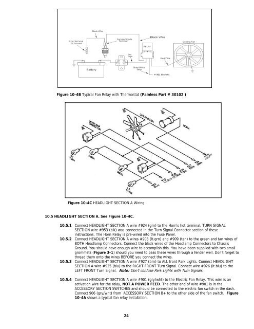
Figure 10-4C HEADLIGHT SECTION A <strong>Wiring</strong><br />
10.5 HEADLIGHT SECTION A. See Figure 10-4C.<br />
10.5.1 Connect HEADLIGHT SECTION A wire #924 (grn) to the Horn's hot terminal. TURN SIGNAL<br />
SECTION wire #953 (blk) was connected in the Turn Signal Connector section of these<br />
instructions. The Horn Relay is pre-wired into the Fuse Panel.<br />
10.5.2 Connect HEADLIGHT SECTION A wires #908 (lt.grn) and #909 (tan) to the green and tan wires of<br />
BOTH Headlamp Connectors. Connect the black wires of the Headlamp Connectors to Chassis<br />
Ground. You should have enough wire to accomplish this. You have been supplied with two small<br />
grommets (Figure 3-1) should you need to pass these wires through a fender well. Don't forget to<br />
thread them onto the wires BEFORE you connect the wires.<br />
10.5.3 Connect HEADLIGHT SECTION A wire #927 (brn) to ALL front Park Lights. Connect HEADLIGHT<br />
SECTION A wire #925 (blu) to the RIGHT FRONT Turn Signal. Connect wire #926 (lt.blu) to the<br />
LEFT FRONT Turn Signal. Note: Don't confuse Park Lights with Turn Signals.<br />
10.5.4 Connect HEADLIGHT SECTION A wire #901 (gry/wht) to the Electric Fan Relay. This wire is an<br />
activation wire for the relay, NOT A POWER FEED. The other end of wire #901 is in the<br />
ACCESSORY SECTION SWITCHES and should be connected to the electric fan switch in the dash.<br />
Connect 906 (gry/wht) from ACCESSORY SECTION B+ to the other side of the fan switch. Figure<br />
10-4A shows a typical fan relay installation.<br />
24


