

Edelbrock 2838 Intake Manifold Installation Instructions - Jegs
Edelbrock 2838 Intake Manifold Installation Instructions - Jegs
Edelbrock 2838 Intake Manifold Installation Instructions - Jegs

Create successful ePaper yourself
Turn your PDF publications into a flip-book with our unique Google optimized e-Paper software.
®<br />
Carbureted Victor Jr. 4.6L <strong>Intake</strong> <strong>Manifold</strong><br />
For 4.6L SOHC Ford V8<br />
Catalog #2839 (with Timing Control Module)<br />
& #<strong>2838</strong> (without Timing Control Module)<br />
INSTALLATION INSTRUCTIONS<br />
PLEASE study these instructions carefully before beginning this installation. Most installations can be accomplished with common tools and<br />
procedures. However, you should be familiar with and comfortable working on your vehicle. If you do not feel comfortable performing this installation,<br />
it is recommended to have the installation completed by a qualified mechanic. If you have any questions, please call our Technical Hotline at:<br />
1-800-416-8628, 7:00 am - 5:00 pm, Pacific Standard Time, Monday through Friday or e-mail us at <strong>Edelbrock</strong>@<strong>Edelbrock</strong>.com.<br />
IMPORTANT NOTE: Proper installation is the responsibility of the installer. Improper installation<br />
will void your warranty and may result in poor performance and engine or vehicle damage.<br />
DESCRIPTION: This intake manifold is designed to allow the use of a carburetor on a Ford 4.6L Modular Single Overhead Cam engine. This will<br />
eliminate the use of the OEM fuel injection system and is intended for longblocks that have been installed in early model or custom vehicles. It is also<br />
intended for use in racing classes where fuel injection is not allowed or is not desirable. The #2839 includes an electronic Timing Control Module,<br />
which picks up MAP, Crank Position, and Cam Position, and drives the stock Coil-on-Plug system. The Timing Control Module comes loaded with a<br />
basic timing curve and rev limit, both of which can be easily modified using a laptop and the included Pro-Data software. The #<strong>2838</strong> does not include<br />
the electronics, but they may be purchased seperately as part #91237.<br />
KIT CONTENTS (<strong>2838</strong> & 2839):<br />
❑ 1 Victor Jr. <strong>Intake</strong> <strong>Manifold</strong><br />
❑ 1 Fitting; 3/8 NPT to 3/4” hose<br />
❑ 2 Plugs; 3/8 NPT<br />
❑ 8 Bolt; M6 x 1.0 x 30mm hex flange head<br />
2839 Only:<br />
❑ 1 <strong>Edelbrock</strong>/MSD Timing Control Module<br />
❑ 1 2-Bar <strong>Manifold</strong> Absolute Pressure (MAP) Sensor<br />
❑ 1 MAP Sensor Mounting Bracket<br />
❑ 1 9-Pin Serial Cable<br />
❑ 1 Wiring Harness<br />
❑ 1<br />
❑ 1<br />
❑ 1<br />
❑ 2<br />
❑ 2<br />
❑ 2<br />
❑ 2<br />
❑ 2<br />
❑ 2<br />
INSTALLATION PROCEDURE<br />
Pro-Data Software <strong>Installation</strong> CD<br />
1/8 NPT to 1/4” Hose Adapter Fitting<br />
Mounting Hardware Kit Including:<br />
❑ 4 Sheet Metal Screws<br />
❑ 4 Mounting Grommets<br />
❑ 4 Mounting Spacers<br />
5mm x .8 x 30mm Torx Button Head Screws<br />
5mm Lock Nuts<br />
1/4” rubber hose; 9” long<br />
3/16” Flat Washers<br />
5/16”-18 x 1/2” Hex Cap Bolt<br />
5/16” Flat Washers<br />
NOTE: This intake manifold is not designed for use in vehicles equipped with the 4.6L engine from the factory. It is only intended to be used on engines<br />
that have been swapped into a custom application where modifications can be made as necessary. These installation instructions do not attempt to<br />
cover the steps necessary to convert a fuel injected vehicle to carburetion, they only cover what is needed to install this intake and the related<br />
electronics on a properly prepared longblock.<br />
MANIFOLD INSTALLATION:<br />
1. Use only the recommended OEM intake gaskets with this manifold.<br />
2. Fully clean the intake manifold and cylinder head flanges, as well as<br />
the end seal surfaces of the engine block. No sealants or adhesives<br />
are necessary.<br />
3. Install the manifold on the block. Lightly coat the manifold bolts with<br />
30W motor oil then gently thread them into the heads to hold the<br />
intake in place. Do not apply any torque to the bolts at this time.<br />
4. Install the themostat and allow it to drop into the machined recess.<br />
The o-ring supplied with the thermostat should then be pressed in<br />
and compressed by the thermostat housing.<br />
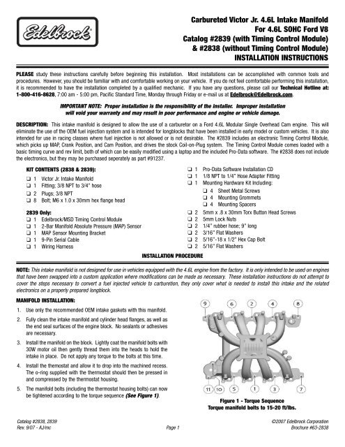
5. The manifold bolts (including the thermostat housing bolts) can now<br />
be tightened according to the torque sequence (See Figure 1).<br />
Figure 1 - Torque Sequence<br />
Torque manifold bolts to 15-20 ft/lbs.<br />
Catalog #<strong>2838</strong>, 2839<br />
Rev. 9/07 - AJ/mc<br />
Page 1<br />
©2007 <strong>Edelbrock</strong> Corporation<br />
Brochure #63-<strong>2838</strong>
MAP SENSOR INSTALLATION:<br />
1. Apply a bit of liquid Teflon thread sealant to the threads of the<br />
supplied 1/8” NPT to 1/4” hose fitting and install the fitting into the<br />
1/8” NPT hole in the intake manifold plenum (See Figure 2).<br />
2. Attach the MAP sensor to the supplied bracket (See Figure 3).<br />
3. Install the sensor/bracket assembly on the intake manifold using the<br />
throttle cable bracket bolt hole bosses (See Figure 4). If using a<br />
Ford throttle cable bracket, install the sensor assembly on top of the<br />
bracket.<br />
4. Connect the sensor to the fitting with the supplied hose.<br />
Figure 3 - Sensor/Bracket Assembly<br />
Figure 2 - Map Sensor Fitting<br />
Figure 4 - Assembly Mounting<br />
TIMING CONTROL MODULE INSTALLATION:<br />
1. Using the hardware supplied with the Timing Control Module, mount<br />
the unit in a suitable location inside the engine compartment, such<br />
as the firewall, or inner fender. Mount the module so that the main<br />
harness can be easily connected. Bear in mind that the shorter side<br />
of the coil pack wires will be routed to the passenger side bank.<br />
2. Route the harness from the control module to the passenger side of<br />
the engine, towards the front. Locate the Crankshaft Position<br />
Sensor connector. It is a two wire connector with red and black<br />
wires at the end of a long section of harness which is encased in a<br />
smooth, rubberized, dark grey heatshield. Route this line down the<br />
passenger side of the engine, and connect it to the Crankshaft<br />
Position Sensor. The Crankshaft Position Sensor is located on the<br />
front of the passenger side of the engine, just above the oil pan rail.<br />
3. Locate the MAP Sensor connector. It is the three wire connector<br />
with orange, green, and brown wires. Connect this to the MAP<br />
Sensor on the rear of the manifold.<br />
4. Locate the Camshaft Position Sensor connector. It is a two wire<br />
connector with tan and brown wires extending from a length of<br />
rubberized heatshield. Route this wire along the driver side of the<br />
intake manifold and down the front of the block. Connect the wire<br />
to the Camshaft Position Sensor, located at the front driver side of<br />
the block, just below the valve cover rail.<br />
5. Attach the wire connectors to the coil pack associated with the<br />
attached cylinder number. The shorter coil wire set will be routed to<br />
the passenger side bank, while the longer wire set will be routed<br />
along the driver side bank. The connector on the end of the harness<br />
will go to the cylinder closest to the front of the engine and the rest<br />
of the connectors should line up with their respective coils.<br />
6. Locate the portion of the harness with the gray, four wire connector<br />
extending from the coil pack wire set. The ring tab is a ground and<br />
should be mounted to an unpainted area of the block or frame. The<br />
two wire plug that also extends from the gray connector will be cut<br />
off, and the red wire should be routed to a switched (only has power<br />
when the key is on) 12 volt power source. The yellow and brown<br />
wire will not be used and should be taped off to prevent a short.<br />
7. The loose yellow wire that extends directly out of the main harness<br />
plug is the tachometer lead. This wire should be taped off and<br />
secured if you are not using a tach. The pink and blue wires will<br />
attach to a two-step timing retard box if you are using one,<br />
otherwise they should be taped off and secured, as well.<br />
Catalog #<strong>2838</strong>, 2839<br />
Rev. 9/07 - AJ/mc<br />
Page 2<br />
©2007 <strong>Edelbrock</strong> Corporation<br />
Brochure #63-<strong>2838</strong>
CARBURETOR RECOMMENDATIONS: <strong>Manifold</strong> will accept any standard square bore flange carburetor, including all <strong>Edelbrock</strong> Thunder AVS and<br />
Performer models. Due to engine efficiency and runner design, we recommend the use of a 600 cfm or larger carburetor. Dyno testing was<br />
conducted with our 750 cfm high performance carburetor (part #1407). The best results were achieved with the stock primary jet, .075” x .047”<br />
metering rods (part #1459), and .100” secondary jets (part #1428). We recommend using the stock calibration to establish a baseline, and tuning<br />
accordingly from there. A smaller carburetor, such as the Thunder AVS 650 cfm (part #1806), would be preferable for street use particularly if the<br />
stock camshaft will be reused.<br />
CAMSHAFT AND HEADERS: <strong>Edelbrock</strong> does not currently make a camshaft for this engine. Although the stock cam can be used, we recommend<br />
a more aggressive grind that will take full advantage of the improved runner design and flow capacity. Headers are not strictly necessary, but their<br />
use is strongly recommend. Primary tube diameter should be no less than 1-5/8” with a 3” collector.<br />
THROTTLE AND ACCESSORY BRACKETS: Throttle and kickdown brackets on some vehicles may require modification to fit. A universal throttle<br />
cable bracket is also available under the Russell brand name (part #611069).<br />
DISTRIBUTOR: The Ford 4.6L Modular engine uses a direct fire Coil-On-Plug ignition distributorless ignition system. A standalone ignition control<br />
module is available seperately (#91237) and is included with the #2839 version of this manifold. Please refer to the seperate instruction sheet for<br />
specific installation and tuning recommendations.<br />
Catalog #<strong>2838</strong>, 2839<br />
Rev. 9/07 - AJ/mc<br />
Page 3<br />
©2007 <strong>Edelbrock</strong> Corporation<br />
Brochure #63-<strong>2838</strong>
®<br />
<strong>Edelbrock</strong> Corporation • 2700 California St. • Torrance, CA 90503<br />
Tech-Line: 1-800-416-8628 • E-Mail: <strong>Edelbrock</strong>@<strong>Edelbrock</strong>.com<br />
Catalog #<strong>2838</strong>, 2839<br />
Rev. 9/07 - AJ/mc<br />
©2007 <strong>Edelbrock</strong> Corporation<br />
Brochure #63-<strong>2838</strong>


