Edelbrock 70055 Nitrous System Installation Instructions - Jegs
Edelbrock 70055 Nitrous System Installation Instructions - Jegs
Edelbrock 70055 Nitrous System Installation Instructions - Jegs
You also want an ePaper? Increase the reach of your titles
YUMPU automatically turns print PDFs into web optimized ePapers that Google loves.
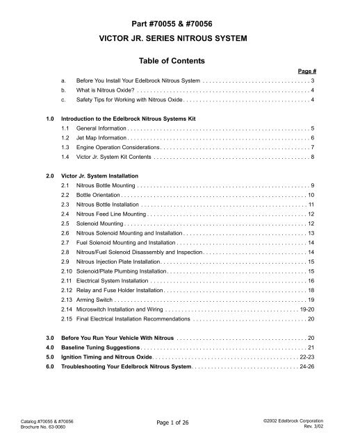
Part #<strong>70055</strong> & #70056<br />
VICTOR JR. SERIES NITROUS SYSTEM<br />
Table of Contents<br />
Page #<br />
a. Before You Install Your <strong>Edelbrock</strong> <strong>Nitrous</strong> <strong>System</strong> . . . . . . . . . . . . . . . . . . . . . . . . . . . . . . . . . 3<br />
b. What is <strong>Nitrous</strong> Oxide? . . . . . . . . . . . . . . . . . . . . . . . . . . . . . . . . . . . . . . . . . . . . . . . . . . . . . 4<br />
c. Safety Tips for Working with <strong>Nitrous</strong> Oxide . . . . . . . . . . . . . . . . . . . . . . . . . . . . . . . . . . . . . . . 4<br />
1.0 Introduction to the <strong>Edelbrock</strong> <strong>Nitrous</strong> <strong>System</strong>s Kit<br />
1.1 General Information . . . . . . . . . . . . . . . . . . . . . . . . . . . . . . . . . . . . . . . . . . . . . . . . . . . . . . . . 5<br />
1.2 Jet Map Information . . . . . . . . . . . . . . . . . . . . . . . . . . . . . . . . . . . . . . . . . . . . . . . . . . . . . . . . 6<br />
1.3 Engine Operation Considerations. . . . . . . . . . . . . . . . . . . . . . . . . . . . . . . . . . . . . . . . . . . . . . 7<br />
1.4 Victor Jr. <strong>System</strong> Kit Contents . . . . . . . . . . . . . . . . . . . . . . . . . . . . . . . . . . . . . . . . . . . . . . . . 8<br />
2.0 Victor Jr. <strong>System</strong> <strong>Installation</strong><br />
2.1 <strong>Nitrous</strong> Bottle Mounting . . . . . . . . . . . . . . . . . . . . . . . . . . . . . . . . . . . . . . . . . . . . . . . . . . . . . 9<br />
2.2 Bottle Orientation . . . . . . . . . . . . . . . . . . . . . . . . . . . . . . . . . . . . . . . . . . . . . . . . . . . . . . . . . 10<br />
2.3 <strong>Nitrous</strong> Bottle <strong>Installation</strong> . . . . . . . . . . . . . . . . . . . . . . . . . . . . . . . . . . . . . . . . . . . . . . . . . . . 11<br />
2.4 <strong>Nitrous</strong> Feed Line Mounting . . . . . . . . . . . . . . . . . . . . . . . . . . . . . . . . . . . . . . . . . . . . . . . . . 12<br />
2.5 Solenoid Mounting . . . . . . . . . . . . . . . . . . . . . . . . . . . . . . . . . . . . . . . . . . . . . . . . . . . . . . . . 12<br />
2.6 <strong>Nitrous</strong> Solenoid Mounting and <strong>Installation</strong> . . . . . . . . . . . . . . . . . . . . . . . . . . . . . . . . . . . . . . 13<br />
2.7 Fuel Solenoid Mounting and <strong>Installation</strong> . . . . . . . . . . . . . . . . . . . . . . . . . . . . . . . . . . . . . . . . 14<br />
2.8 <strong>Nitrous</strong>/Fuel Solenoid Disassembly and Inspection. . . . . . . . . . . . . . . . . . . . . . . . . . . . . . . . 14<br />
2.9 <strong>Nitrous</strong> Injection Plate <strong>Installation</strong>. . . . . . . . . . . . . . . . . . . . . . . . . . . . . . . . . . . . . . . . . . . . . 15<br />
2.10 Solenoid/Plate Plumbing <strong>Installation</strong>. . . . . . . . . . . . . . . . . . . . . . . . . . . . . . . . . . . . . . . . . . . 15<br />
2.11 Electrical <strong>System</strong> <strong>Installation</strong> . . . . . . . . . . . . . . . . . . . . . . . . . . . . . . . . . . . . . . . . . . . . . . . . 16<br />
2.12 Relay and Fuse Holder <strong>Installation</strong> . . . . . . . . . . . . . . . . . . . . . . . . . . . . . . . . . . . . . . . . . . . . 18<br />
2.13 Arming Switch . . . . . . . . . . . . . . . . . . . . . . . . . . . . . . . . . . . . . . . . . . . . . . . . . . . . . . . . . . . 19<br />
2.14 Microswitch <strong>Installation</strong> and Wiring . . . . . . . . . . . . . . . . . . . . . . . . . . . . . . . . . . . . . . . . . 19-20<br />
2.15 Final Electrical <strong>Installation</strong> Recommendations . . . . . . . . . . . . . . . . . . . . . . . . . . . . . . . . . . . 20<br />
3.0 Before You Run Your Vehicle With <strong>Nitrous</strong> . . . . . . . . . . . . . . . . . . . . . . . . . . . . . . . . . . . . . . . . 20<br />
4.0 Baseline Tuning Suggestions . . . . . . . . . . . . . . . . . . . . . . . . . . . . . . . . . . . . . . . . . . . . . . . . . . . 21<br />
5.0 Ignition Timing and <strong>Nitrous</strong> Oxide. . . . . . . . . . . . . . . . . . . . . . . . . . . . . . . . . . . . . . . . . . . . . 22-23<br />
6.0 Troubleshooting Your <strong>Edelbrock</strong> <strong>Nitrous</strong> <strong>System</strong>. . . . . . . . . . . . . . . . . . . . . . . . . . . . . . . . . 24-26<br />
Catalog #<strong>70055</strong> & #70056<br />
Brochure No. 63-0060<br />
Page 1 of 26<br />
©2002 <strong>Edelbrock</strong> Corporation<br />
Rev. 3/02
Thank You….<br />
…for purchasing an <strong>Edelbrock</strong> <strong>Nitrous</strong> Oxide Injection <strong>System</strong>.<br />
<strong>Nitrous</strong> Oxide injection is one of the most exciting performance enhancements, for the dollar invested, on the market today.<br />
With the use of nitrous oxide come some important safety considerations. This manual has been written to help you during<br />
the installation and use of your <strong>Edelbrock</strong> <strong>Nitrous</strong> <strong>System</strong>. Please read it completely before you install and use your<br />
system. Please pay close attention to the safety information at the beginning of each section. The information contained<br />
there specifically pertains to each of the components and installation methodologies within the section.<br />
Please take the time to read and understand the following….<br />
By installing your <strong>Edelbrock</strong> <strong>Nitrous</strong> <strong>System</strong>, you indicate you have read this document and you agree with the terms stated<br />
below:<br />
It is the responsibility of the purchaser to follow all installation instruction guidelines and safety procedures supplied with<br />
the <strong>Edelbrock</strong> <strong>Nitrous</strong> <strong>System</strong>s. It is also the responsibility of the purchaser to determine the compatibility of the product<br />
with the vehicle or the device on which the purchaser intends to install it.<br />
<strong>Edelbrock</strong> Corporation assumes no responsibility for damages occurring from misuse, abuse, improper installation,<br />
improper operation, lack of responsible care, or all previously-stated reasons resulting from incompatibility with other<br />
manufacturer’s products and/or systems.<br />
<strong>Edelbrock</strong> Corporation neither recommends nor condones the use of products manufactured or sold by <strong>Edelbrock</strong><br />
Corporation for use on vehicles, which may be driven on public roads or highways, and assumes no responsibility for<br />
damages incurred by such use.<br />
<strong>Edelbrock</strong> Corporation assumes no responsibility for damages incurred by the use of products manufactured or sold by<br />
<strong>Edelbrock</strong> Corporation on vehicles used for competition or racing.<br />
<strong>Edelbrock</strong> General Warranty<br />
It is the constant endeavor of <strong>Edelbrock</strong> Corporation to give our customers the highest quality products obtainable.<br />
<strong>Edelbrock</strong> warrants each new product, except Performer Series Carburetors, Race Division Parts, Tubular Exhaust<br />
<strong>System</strong>s, RPM Series Mufflers, Cat-Back <strong>System</strong>s and Performer IAS Shock Absorbers which are warranted separately,<br />
to be free from defects in both workmanship and material for a period of one (1) year from the date of purchase, provided<br />
that the product is properly installed, subjected to normal use and service and that the product is not modified or changed<br />
in any way, negligence by customer or installer or used for racing or competition purposes.<br />
Our warranty service and repair facility is located at 2700 California Street, Torrance, California 90503. Customers who<br />
believe they have a defective product should either return it to the dealer from which it was purchased or ship it directly to<br />
<strong>Edelbrock</strong> along with proof of purchase and a complete description of the problem. The product must be returned freight<br />
pre-paid. If a thorough inspection of the product by the factory indicates defects in workmanship or material, our sole<br />
obligation shall be to repair or replace the product. Warranty covers only the product itself and not the cost of installation<br />
or removal.<br />
<strong>Edelbrock</strong> Corporation shall not be liable for any and all consequential damages occasioned by the breach of any<br />
written or implied warranty pertaining to this sale in excess of the purchase price of the product sold.<br />
If you have any questions regarding a product or installation, please contact our Technical Department, toll free<br />
at 1-800-416-8628 from 7:00am to 5:00pm PST, Monday through Friday.<br />
Thank you again for choosing <strong>Edelbrock</strong> <strong>Nitrous</strong> <strong>System</strong>s.<br />
Catalog #<strong>70055</strong> & #70056<br />
Brochure No. 63-0060<br />
Page 2 of 26<br />
©2002 <strong>Edelbrock</strong> Corporation<br />
Rev. 3/02
Caution!!!<br />
Before You Install Your <strong>Edelbrock</strong> <strong>Nitrous</strong> <strong>System</strong>…<br />
Please read this <strong>Installation</strong> manual fully before installing this system.<br />
You will need to have available the following tools:<br />
Hand Tools<br />
❑ Socket set including ratchets and extensions<br />
❑ Screwdrivers<br />
❑ Pliers<br />
❑ Bench vise<br />
❑ Wire crimping pliers, wire strippers<br />
❑ Floor jack<br />
❑ Razor blade or other sharp, flat edged cutting instrument<br />
❑ Vehicle jackstands<br />
❑ Safety glasses<br />
❑ Timing light<br />
Power Tools<br />
❑ Power drill<br />
❑ Drill bits<br />
You should understand the following skills:<br />
❑ Power tool safety procedures<br />
❑ Undercar safety procedures<br />
❑ Proper measuring techniques<br />
❑ Proper electrical assembly techniques<br />
❑ Basic engine operation and tuning techniques which include:<br />
Fuel pressure measurement techniques<br />
Timing adjustment techniques<br />
℡<br />
Anytime you have questions or concerns with your <strong>Edelbrock</strong> <strong>Nitrous</strong> <strong>System</strong>, please<br />
call our technical support hotline at<br />
1-800-416-8628 before you start your engine.<br />
Catalog #<strong>70055</strong> & #70056<br />
Brochure No. 63-0060<br />
Page 3 of 26<br />
©2002 <strong>Edelbrock</strong> Corporation<br />
Rev. 3/02
WHAT IS NITROUS OXIDE?<br />
<strong>Nitrous</strong> Oxide is a cryogenic gas composed of nitrogen and oxygen molecules. It is stored as a “gas over a liquid” which<br />
means that both liquid and gaseous nitrous oxide is delivered into your engine. It is 36% oxygen by weight, which is what<br />
produces the added horsepower. By injecting more oxygen (and a corresponding fuel signal), we create the additional<br />
power much like a supercharger or a turbocharger does.<br />
<strong>Nitrous</strong> Oxide is considered an “oxidizer” and not a fuel. <strong>Nitrous</strong> oxide is non-flammable by itself. Because nitrous oxide<br />
is a cryogenic, the same safety methods in handling dry ice apply to nitrous. Direct contact with the skin will cause a burn<br />
similar to contact with dry ice. The exception in using nitrous oxide comes from increased breathing hazards associated<br />
with the gaseous properties of nitrous oxide.<br />
<strong>Nitrous</strong> Oxide is offered for sale in two common grades, which are U.S.P., and Nytrous Plus. U.S.P. nitrous oxide is medical<br />
grade nitrous oxide. Its common use is dental and veterinary anesthesia as well as use as a propellant in food such as<br />
canned whip cream. U.S.P. is not available to the public and would provide no advantage in the making of horsepower over<br />
the automotive grade nitrous oxide.<br />
Nytrous Plus was specifically designed for automotive consumption and differs from U.S.P. in that it contains trace amounts<br />
of sulfur dioxide (100 parts per million or “PPM”) added to prevent substance abuse. The Sulfur Dioxide is an irritant to all<br />
of your breathing passageways and will cause sore throats and sore nasal passages. Nytrous Plus was specifically<br />
created for automotive applications and is available for sale to the public at many speed shops across the USA.<br />
<br />
Safety Steps For Working With <strong>Nitrous</strong> Oxide<br />
1. Never inhale Nytrous Plus (<strong>Nitrous</strong> oxide (N 2 O) for vehicular use) as continued exposure can cause death.<br />
Nytrous Plus has a maximum of 100 parts per million (ppm) of sulfur dioxide and will cause irritation to nose<br />
and throat passageways.<br />
2. When working around any high-pressure gas including nitrous oxide, take all precautions to ensure that<br />
exposure to nitrous oxide is minimized.<br />
3. Do not vent nitrous oxide to atmosphere in confined spaces. Only vent nitrous oxide in well-ventilated and<br />
open areas.<br />
4. Liquid nitrous oxide can cause burns to human flesh so protect all skin in and around your hands, arms and<br />
face. Wear safety glasses and rubber gloves to protect from liquid nitrous oxide splatter.<br />
5. When venting down the nitrous system, vent the line down closest to the nitrous bottle.<br />
6. Do not use any form of Teflon tape as sealant on fitting connections. Use only Teflon paste.<br />
7. When washing components, ensure the clean components are completely dry, free of oils, and solvents.<br />
Failure to remove all liquids could cause component or system failure.<br />
8. Always turn the bottle off before making any repairs to the nitrous delivery system.<br />
9. To safely release nitrous oxide in a pressurized line;<br />
a. Position vehicle in a well-ventilated, unconfined space.<br />
b. Turn bottle off.<br />
c. Slowly loosen the nitrous feed line at the bottle until you hear a light hissing noise.<br />
d. Allow the entire nitrous pressure to vent from the line.<br />
e. Perform your work on the system.<br />
f. Tighten the nitrous line to the bottle.<br />
g. Slowly open the nitrous bottle valve, listening for leaks.<br />
h. Perform leak checks on all effected fittings and the bottle fitting.<br />
Catalog #<strong>70055</strong> & #70056<br />
Brochure No. 63-0060<br />
Page 4 of 26<br />
©2002 <strong>Edelbrock</strong> Corporation<br />
Rev. 3/02
1.0 Introduction to your <strong>Edelbrock</strong> Victor Jr. <strong>Nitrous</strong> <strong>System</strong><br />
….about this manual!<br />
Within the pages of this manual is information, safety tips and operation instructions for your new <strong>Edelbrock</strong> <strong>Nitrous</strong><br />
<strong>System</strong>. Watch for these symbols to know where to go for information.<br />
<br />
<br />
℡<br />
….There is safety related information here.<br />
….shows where technical information about your vehicle or specific skills that may help during<br />
installation.<br />
….call <strong>Edelbrock</strong> Technical support hotline for more information.<br />
1.1 General Information<br />
The <strong>Edelbrock</strong> Victor Jr. <strong>Nitrous</strong> <strong>System</strong>s are intended for use on domestic style V-8 engines using<br />
single Dominator-flange carburetors (Part #<strong>70055</strong>) and square-flange 4 bbl. carburetors (Part<br />
#70056). Horsepower and torque increases can vary with engine displacement, equipment upgrades and<br />
modifications. Approximate power increase estimates can be made based on the mass flow of nitrous<br />
oxide into the engine.<br />
These types of systems utilize an adjustable plate that sandwiches in between the throttle body and the<br />
throttle body mounting pad on the intake manifold. The adjustability comes from the ability of the plate to<br />
accept different orifice-sized jets. The plate has jet fittings at opposite ends of the plate that control the<br />
amount of nitrous oxide and fuel flow into the engine.<br />
This system has been designed with some flexibility as to where certain components can be located within<br />
the engine compartment. The electrical components have properly-sized and ample lengths of wire for<br />
some flexibility on where voltage signals are intercepted on the electrical system.<br />
The solenoid and microswitch brackets have a universal shape to allow for adjustability in placement and<br />
location of these components. The solenoids have ample feed line lengths for many different manifold, air<br />
cleaner, throttle body configurations and the microswitch bracket will allow for several different positions.<br />
This system includes the bottle (shipped empty), bottle feed line and universal footprint steel bottle<br />
brackets. The mounting brackets also include rubber insulators to protect the surface of your nitrous bottle<br />
while mounted in the brackets. When installing your nitrous bottle, pay close attention to the installation<br />
instructions for the location of your bottle. Make sure that the installation of your bottle does not interfere<br />
with any systems that may lie under the location where you plan to drill holes for mounting the brackets.<br />
Call your local automotive store, motorcycle shop or race track for refilling of your bottle. Trust a<br />
professional to properly fill your bottle and reference your installation manual when re-installing your filled<br />
bottle back into your vehicle.<br />
Always take care when handling a full bottle of nitrous oxide. Please reference this manual for further<br />
safety measures to take during the handling of a nitrous oxide bottle.<br />
Please follow all safety methods during the installation of your <strong>Edelbrock</strong> <strong>Nitrous</strong> <strong>System</strong>, and follow all<br />
vehicle regulations and road laws when using your nitrous system.<br />
Catalog #<strong>70055</strong> & #70056<br />
Brochure No. 63-0060<br />
Page 5 of 26<br />
©2002 <strong>Edelbrock</strong> Corporation<br />
Rev. 3/02
1.2 Jet Map Information<br />
<strong>Edelbrock</strong> engineering has conducted dyno testing with the Victor Jr. system to provide jetting maps for<br />
two separate plates at different jetting levels. These jet combinations are supplied with this system to<br />
enable you to vary your engine’s power output. On a typical mildly to highly modified 350 or larger cubic<br />
inch engine, you can expect the following approximate power gains for each of the jetting levels:<br />
Dominator-Flange Jet Map<br />
<strong>Nitrous</strong>/Fuel Jetting Approx. HP Gains Timing Adj.<br />
38/39 200hp 30 Deg. Total<br />
54/54 300hp 24 Deg. Total<br />
61/58 400hp 20 Deg. Total<br />
Square-Flange Jet Map<br />
<strong>Nitrous</strong>/Fuel Jetting Approx. HP Gains Timing Adj.<br />
39/39 200hp 28 Deg. Total<br />
48/46 300hp 24 Deg. Total<br />
58/56 400hp 20 Deg. Total<br />
The dyno tests were conducted at <strong>Edelbrock</strong> using a mildly modified 500 cubic inch engine. Modifications<br />
included <strong>Edelbrock</strong> intake manifold, dyno headers and improved ignition. These tests were conducted with<br />
950 psi nitrous and 7.5 psi fuel pressure. All stated timing adjustments listed in jet maps is where the<br />
motor being tested worked best. Final timing should be adjusted to achieve best power and/or MPH per<br />
application. See section “5.0 Ignition Timing and <strong>Nitrous</strong>” for more information on timing selection.<br />
These jetting patterns are designed to be rich and will provide the above-listed power settings under<br />
normal operational usage of this system. Any variations in jetting patterns other than what is listed above<br />
and engine damage could occur. Please contact <strong>Edelbrock</strong> Technical Department with any questions you<br />
have concerning jetting patterns and their effects on engine performance.<br />
<strong>Edelbrock</strong> recommends using Champion C-64-C or equivalent spark plugs.<br />
The fuel used should be 110 Octane or better.<br />
The Victor Jr. Series <strong>Nitrous</strong> <strong>System</strong>s are intended for single-plane manifolds only. Do not use a<br />
dual-plane manifold with the Victor Jr. Series <strong>Nitrous</strong> <strong>System</strong>s. In testing, we found that dual-plane<br />
manifolds have some distribution problems at these super high flow rates that could cause serious engine<br />
damage.<br />
Catalog #<strong>70055</strong> & #70056<br />
Brochure No. 63-0060<br />
Page 6 of 26<br />
©2002 <strong>Edelbrock</strong> Corporation<br />
Rev. 3/02
1.3 Engine Operation Considerations<br />
When used correctly, nitrous oxide safely elevates cylinder pressures and temperatures while increasing<br />
combustion rate. These characteristics make the engine more sensitive to detonation. To ensure proper<br />
performance, engine and drive line life, the following tips are suggested:<br />
• Adequate Fuel Pressure and Delivery<br />
When designing your fuel system, plan on your pumps and lines flowing at least 0.10 gallons per hour per<br />
horsepower. The testing at <strong>Edelbrock</strong> was conducted with a fuel pressure of 7 to 7.5 psi. Any<br />
variations from this fuel pressure will cause your final air/fuel ratio to change. Consult our Technical<br />
Department for any questions on fuel pressure and its effects on final air/fuel ratios when using nitrous<br />
oxide.<br />
• Victor Jr. Fuel <strong>System</strong> Requirements<br />
When using the Victor Jr. Series Kits, the potential horsepower gains are extremely high. The critical area<br />
for continued success with your nitrous system lies in the fuel system. In the case of the Victor Jr. Series<br />
<strong>Nitrous</strong> <strong>System</strong>s, an auxiliary fuel supply system is a required addition to your nitrous system. A high flow<br />
electric fuel pump and high capacity adjustable fuel pressure regulator are both recommended to ensure<br />
the fuel flow rate is enough to ensure proper system operation. The minimum size we recommend for the<br />
fuel inlet feed line is a -6 (3/8” inch), with a size of -8 (1/2” inch) recommended for the higher horsepower<br />
settings.<br />
• Victor Jr. <strong>System</strong> Monitoring Requirements<br />
Fuel pressure and nitrous pressure gauges are very important. Your fuel pressure must be set properly<br />
and a gauge is the only sure way to monitor system performance. The same is true of the nitrous bottle<br />
pressure. A nitrous pressure gauge is the only way to be ensure that your system calibrations are within<br />
the parameters required of your horsepower settings.<br />
• Fuel Quality<br />
Because <strong>Nitrous</strong> oxide is an oxidizer, fuel selection is critical. Both octane and fuel consistency affect fuel<br />
burn rate. The oxidizer quality of nitrous oxide will accelerate the burn rate, so we recommend a high<br />
quality of gasoline. We also recommend you use the same grade of gasoline every time you use your<br />
nitrous oxide system. This will help maintain the same fuel burn rate every time.<br />
• Cast Pistons<br />
With all nitrous oxide applications, forged pistons are highly recommended. Because of heightened<br />
potential for detonation, cast pistons are more prone to failure and cannot handle horsepower increases<br />
over 125hp. Due to this fact, the Victor Jr. <strong>Nitrous</strong> <strong>System</strong>s require that the engine has forged<br />
pistons. Never initiate your nitrous system before you are at full-load, wide open throttle conditions. Cast<br />
pistons will not be able to survive this kind of stress.<br />
• Engine <strong>System</strong> Upgrades<br />
With all performance modifications, complementary system upgrades will always serve to elevate the<br />
consistency and longevity of an engine, especially when using nitrous oxide as a power adder.<br />
Modifications such as ignition upgrades, free-flowing exhaust, camshafts, cylinder heads, and manifolds<br />
can all add to the performance of a nitrous oxide-injected engine.<br />
Catalog #<strong>70055</strong> & #70056<br />
Brochure No. 63-0060<br />
Page 7 of 26<br />
©2002 <strong>Edelbrock</strong> Corporation<br />
Rev. 3/02
1.4 Victor Jr. <strong>Nitrous</strong> <strong>System</strong> Kit Contents<br />
Qty.<br />
Description<br />
Plates and Plate Hardware<br />
1 ea. Victor Jr. <strong>Nitrous</strong> Plate, <strong>70055</strong>, 70056 <strong>System</strong><br />
2 ea. Carburetor Gaskets<br />
4 ea. Carb Studs<br />
Solenoids and Solenoid Hardware<br />
2 ea. Performer RPM <strong>Nitrous</strong> Solenoid (Black)<br />
2 ea. Performer RPM Fuel Solenoid (Red)<br />
4 ea. Solenoid Brackets with Screws (4 ea)<br />
4 ea. 12” <strong>Nitrous</strong> Feed Line (Blue), Solenoid to Plate<br />
4 ea. 12” Fuel Feed Line (Red), Solenoid to Plate<br />
2 ea. 12” -6AN <strong>Nitrous</strong> Feed Line (Blue)<br />
Fittings<br />
2 ea. N2O Filter Fitting, 6AN x 1/4” NPT, Blue<br />
2 ea. 6AN x 1/4” NPT Fuel Fitting, Red<br />
2 ea. 3AN x 1/8” NPT Flare Tee, Blue<br />
2 ea. 3AN x 1/8” NPT Flare Tee, Red<br />
1 ea. 6AN Flare Tee<br />
Jets<br />
1 ea. Jet Pack<br />
Bottle and Bottle Hardware<br />
1 ea. 10lb, <strong>Nitrous</strong> Bottle<br />
1 pr. <strong>Nitrous</strong> Bottle Bracket Set (1 Tall, 1 Short)<br />
1 ea. 660 Bottle Nut and Teflon Washer<br />
1 ea. 14’ <strong>Nitrous</strong> Feed Line, Bottle to Solenoid<br />
Electrical <strong>System</strong> Components<br />
1 ea. Electrical Component Package (see page 16 for BOM)<br />
Technical Information<br />
1 ea. Performer <strong>System</strong> Information Packet<br />
Catalog #<strong>70055</strong> & #70056<br />
Brochure No. 63-0060<br />
Page 8 of 26<br />
©2002 <strong>Edelbrock</strong> Corporation<br />
Rev. 3/02
2.0 Victor Jr. <strong>System</strong> <strong>Installation</strong>s<br />
2.1 <strong>Nitrous</strong> Bottle Mounting<br />
The nitrous oxide storage cylinder is typically called a “nitrous bottle”. It is an aluminum cylinder, designed<br />
and manufactured to withstand very high pressures. The valve on top of the bottle is a high-flow design<br />
that allows easy opening and closing which controls the nitrous flow to the engine compartment.<br />
Accurate calibration of your nitrous system depends on the bottle remaining at a stable temperature. In<br />
vehicles (such as Corvettes) where the bottle must be mounted in an area subject to direct sunlight, it is<br />
suggested that the bottle be shielded with a bottle blanket.<br />
If the bottle is mounted inside the passenger compartment or in a space that has access to the passenger<br />
compartment such as hatchbacks or vehicles that feature fold down rear seats, the pressure relief device<br />
(PRD valve) must be vented externally from the cockpit. This procedure will prevent the passenger<br />
compartment from filling with a cloud of nitrous oxide, should the safety pressure relief valve rupture. For<br />
more information, please contact our Technical Department.<br />
Special consideration should be made to protect the bottle installation by not placing the bottle in a known<br />
crumple or crash zone within the vehicle. At no time should the bottle be mounted within the seating area<br />
of the passenger compartment of a street-driven vehicle.<br />
Pressure<br />
Relief Device<br />
(PRD)<br />
Bottle Valve Handle<br />
660 High Flow<br />
<strong>Nitrous</strong> Exit<br />
Here is the Performer Bottle Valve. Installed on all bottle valves<br />
used in <strong>Edelbrock</strong> <strong>Nitrous</strong> <strong>System</strong>s, is a Pressure Relief Device<br />
or “PRD”. It is a safety valve designed to vent the contents of the<br />
bottle into the atmosphere in case of a catastrophic event like a<br />
collision. It is also installed to prevent the over-pressurization of<br />
the bottle. Unsafe bottle pressure is caused by over filling or<br />
elevated bottle temperatures.<br />
There are two types of PRDs. Internal piping and external piping.<br />
Internal requires no additional parts. The external type requires<br />
a safety blowdown tube designed to route the gas, if the PRD<br />
happens to rupture to the outside of vehicle. The internal type is<br />
design to vent directly off the bottle into the atmosphere.<br />
<br />
Bottle Safety Information<br />
It is illegal to tamper with or remove this device.<br />
1. Do not attempt to remove the bottle valve. Please return your bottle to <strong>Edelbrock</strong> if service is required to<br />
the siphon tube inside the bottle or the bottle valve itself.<br />
2. Never heat the outside of your nitrous bottle with an open flame like that of a torch.<br />
3. Do not strike the surface of your nitrous bottle with a heavy or sharp object.<br />
4. Do not drop your nitrous bottle.<br />
5. Do not attempt to grind off or destroy any imprinted markings on the face of the bottle.<br />
6. Do not remove, modify or otherwise tamper with the safety valve on the bottle valve.<br />
7. Do not attempt to use a bottle that has been damaged or tampered with.<br />
Racing Vehicles<br />
Before you mount a nitrous bottle in a vehicle intended for use in racing or sanctioned events, check with the<br />
sanctioning association or local racetrack for any rules regarding bottle installation. Most associations require the<br />
bottle be mounted within the confines of the safety roll cage, with the safety pressure relief cap vented away from<br />
the driver’s compartment.<br />
Catalog #<strong>70055</strong> & #70056<br />
Brochure No. 63-0060<br />
Page 9 of 26<br />
©2002 <strong>Edelbrock</strong> Corporation<br />
Rev. 3/02
2.2 Bottle Orientation<br />
Bottle placement is critical to the performance of your nitrous system. It is important to understand how<br />
the bottle valve and siphon tube are assembled to properly orient the bottle in your vehicle and ensure that<br />
it picks up liquid nitrous while undergoing acceleration. All nitrous bottles are assembled so that the bottom<br />
of the siphon tube is at the bottom of the bottle, opposite the bottle label.<br />
An <strong>Edelbrock</strong> nitrous bottle cannot be mounted upside-down. <strong>Edelbrock</strong> does not offer a non-siphon tube<br />
bottle for automotive use. If the bottle must be mounted parallel to the axles of the vehicle (sideways), the<br />
label must be angled at approximately 45 degrees toward the front of the vehicle. This orientation will<br />
position the siphon tube toward the rear and pointing to the lower rear-facing quadrant of the bottle. All of<br />
this positioning information is critical to system operation. It is most important to draw as much liquid<br />
nitrous as possible. The siphon tube cannot do this unless the bottle is positioned correctly.<br />
The most efficient mounting is the lay-down position with the valve handle toward<br />
the front of the vehicle. This position allows the greatest amount of liquid to be<br />
used before the siphon tube begins to pick up gaseous nitrous oxide.<br />
Catalog #<strong>70055</strong> & #70056<br />
Brochure No. 63-0060<br />
Page 10 of 26<br />
©2002 <strong>Edelbrock</strong> Corporation<br />
Rev. 3/02
2.3 <strong>Nitrous</strong> Bottle <strong>Installation</strong><br />
After you have determined the location and orientation of the nitrous bottle, use the following procedure<br />
to install the bottle:<br />
2.3.1 Street Car <strong>Installation</strong>s<br />
1. Disconnect vehicle’s battery.<br />
2. Determine the location of the bottle within the confines of the rear of the vehicle.<br />
3. Once a mounting location has been determined, raise the vehicle (following all safety practices<br />
involved in working on a vehicle from under the vehicle) and verify that there are no fuel lines, fuel<br />
tank(s), brake lines, emissions equipment, or structural members in the way of potential mounting bolt<br />
locations.<br />
Note: It may be necessary to remove the fuel tank depending on the location where you install the<br />
bottle.<br />
4. Install the rubber insulators within the bottle brackets.<br />
5. Slip bottle into the mounting brackets.<br />
6. Using the mounting bracket bolt holes as templates, mark an area for each of the brackets with chalk,<br />
metal marking pen, scribe, or marking pen to locate the bolt placements for drilling.<br />
7. Drill two (2) 3/8” mounting holes for each bracket.<br />
8. If heater blanket is used, brackets must be installed 8 1/2 inches apart from each other.<br />
9. Install the bottle mounting brackets using “Grade 8” bolts, nuts and flat washers (not included with kit).<br />
Use fender washer underneath the vehicle for sheet metal mounting.<br />
10. Tighten the mounting bolts using a thread locking compound (not included with kit).<br />
11. Mock up Safety Blowdown tube on bottle to find where tube will go through floor.<br />
12. Mark floor where tube appears it will go.<br />
13. Using a 1/2” drill bit, drill through floor on mark.<br />
14. Install Safety tube on bottle and cut off excess tube so that only 1 to 2 inches are protruding below<br />
floor.<br />
Shown here is a bottle with a bottle bracket properly<br />
installed with the rubber insulator. The distance between<br />
the bottle brackets is somewhat adjustable. Remember,<br />
mount the short bottle bracket at least 1” from the bottom<br />
of the bottle, and never cover any of the bottle label with a<br />
bottle bracket.<br />
Do not attempt to install the bottle in the bracket without<br />
the rubber insulator. The bottle hoop on the bracket is<br />
designed to include the thickness of the insulator.<br />
2.3.2 Race Car <strong>Nitrous</strong> Bottle <strong>Installation</strong>s<br />
Install the bottle brackets in accordance to race track and/or sanctioning body rules. Contact the<br />
factory for assistance with meeting sanctioning body rules.<br />
2.3.3 <strong>Nitrous</strong> Bottle <strong>Installation</strong>s For Vehicles With Hatchbacks Or Trunk Areas That Are<br />
Connected With The Passenger Compartment.<br />
Please contact <strong>Edelbrock</strong> for more information.<br />
Catalog #<strong>70055</strong> & #70056<br />
Brochure No. 63-0060<br />
Page 11 of 26<br />
©2002 <strong>Edelbrock</strong> Corporation<br />
Rev. 3/02
2.4 <strong>Nitrous</strong> Feed Line Mounting<br />
1. Determine the route your main nitrous feed line will follow. Ensure the path does not route the nitrous<br />
feed line too close to the exhaust system, suspension, electrical lines/components or tires.<br />
2. Attach nitrous supply line to bottle.<br />
3. Feed nitrous line along proposed route.<br />
4. Secure nitrous supply line to underside of vehicle.<br />
Note: Stainless steel covering of the main nitrous feed line is very abrasive. Shield painted<br />
components or sensitive system components like electrical, fuel lines, brake lines or suspension<br />
components to prevent them from contacting main feed line. Rubber hose can be slid over and<br />
retained as a chafe guard.<br />
5. Leave nitrous line loose pending installation of nitrous solenoid.<br />
2.5 Solenoid Mounting<br />
Use the following procedures to install the Performer RPM nitrous solenoids and fuel solenoids.<br />
Note: Remember to use Teflon paste only on pipe threads. Do not use Teflon tape.<br />
Hint:<br />
Placement of the solenoid is often limited by the lack of possible mounting locations in the<br />
engine compartment. However, if possible, observe the following suggestions:<br />
Solenoid Safety Information<br />
1. Keep solenoids and lines away from exhaust components.<br />
2. Trial fit the solenoids with all lines attached to ensure a proper fit.<br />
3. Solenoids may be mounted sideways or upside-down, if necessary.<br />
2.5.1 Preparing To Mount Your Solenoids<br />
1. Locate the universal solenoid brackets and solenoid mounting screws.<br />
2. These solenoid brackets can be modified to clear almost any potental interference around the<br />
carburetor/plate mounting surface. Please look at the pictures or potential solenoid mounting<br />
locations and adapt your brackets according to the needs of your particular application.<br />
Pictured here is an unmodified Performer RPM solenoid bracket with a modified bracket with<br />
solenoid attached, ready for installation on an intake manifold.<br />
The modifications can be performed by clamping the solenoid bracket in a bench vise, or by using<br />
wide jaw pliers.<br />
Catalog #<strong>70055</strong> & #70056<br />
Brochure No. 63-0060<br />
Page 12 of 26<br />
©2002 <strong>Edelbrock</strong> Corporation<br />
Rev. 3/02
2.6 <strong>Nitrous</strong> Solenoid Mounting and <strong>Installation</strong><br />
1. Hold the nitrous solenoid securely (like in a bench vise) being careful not to harm the solenoid or block<br />
the inlet or outlet of the solenoid.<br />
2. Install nitrous filter fitting (Blue fitting 6AN X 1/4 NPT) using liquid Teflon in the inlet port of the nitrous<br />
solenoid.<br />
3. Install the blue 3AN X 1/8 NPT flare tee using liquid Teflon in the outlet port of the nitrous solenoid.<br />
i. Remove nitrous solenoid assembly from vise.<br />
ii. Attach solenoid-mounting bracket to the bottom of nitrous solenoid.<br />
iii. Verify desired mounting location for nitrous solenoid.<br />
4. Install nitrous solenoid. If solenoid-mounting location is difficult to access, leave solenoid loose so the<br />
solenoid inlet and outlet port can be easily accessed.<br />
5. Leave wires loose for electrical system installation.<br />
6. Attach nitrous feed line to the inlet side of the solenoid.<br />
Pictured here is the Performer RPM solenoid mounted on an <strong>Edelbrock</strong><br />
intake manifold using a modified solenoid bracket. The modifications<br />
performed to a solenoid bracket depend on many factors. The<br />
considerations of solenoid placement are the same for both <strong>Nitrous</strong> and<br />
Fuel. The modifications to the solenoid bracket pictured is just an<br />
example. The modifications for all system brackets will be different per<br />
your application.<br />
The line length between the Performer RPM fuel solenoid and the jet fitting<br />
on the injection plate is 8 inches. The line length between the Performer<br />
RPM nitrous solenoid and the jet fitting on the injection plate is 12 inches.<br />
Other factors or components that could potentially interfere with solenoid<br />
placement are:<br />
•Water neck/thermostat housings<br />
•Water fittings<br />
•Distributor housing<br />
•Vacuum advance canister<br />
•Air filter housing<br />
•Throttle linkage passageways<br />
•Valve covers and valve cover fasteners<br />
•EGR passageways<br />
Catalog #<strong>70055</strong> & #70056<br />
Brochure No. 63-0060<br />
Page 13 of 26<br />
©2002 <strong>Edelbrock</strong> Corporation<br />
Rev. 3/02
2.7 Fuel Solenoid Mounting and <strong>Installation</strong><br />
1. Hold the fuel solenoid securely (like in a bench vise) being careful not to harm the solenoid or block<br />
the inlet or outlet of the solenoid.<br />
2. Install 6AN X 1/4 NPT (Red straight fitting) fuel inlet fitting using liquid Teflon in the inlet port of the fuel<br />
solenoid.<br />
3. Install the red 3AN X 1/8 NPT flare tee using liquid Teflon in the outlet port of the fuel solenoid.<br />
4. Remove fuel solenoid assembly from vise.<br />
5. Attach the universal solenoid mounting bracket to the bottom of the fuel solenoid using 2 of the<br />
solenoid mounting screws.<br />
6. Verify the desired mounting location of the fuel solenoid.<br />
7. Install the fuel solenoid. If the solenoid mounting location is difficult to access, leave the solenoid loose<br />
so the solenoid inlet and outlet port can be easily accessed.<br />
8. Leave the wires loose for the electrical system installation.<br />
2.8 <strong>Nitrous</strong>/Fuel Solenoid Disassembly and Inspection<br />
1. Close the valve on the nitrous bottle.<br />
2. Empty the main nitrous supply line.<br />
3. Remove the solenoid from the engine and securely clamp it to a vise, taking great care not to damage<br />
the solenoid.<br />
4. Remove the solenoid cover retaining nut from the top of the solenoid.<br />
5. Remove the coil and housing from the solenoid base.<br />
6. Unscrew the stem from the solenoid base. Do this by using a solenoid stem removal tool or by “double<br />
nutting” the stem and unscrewing the stem from the housing body. Do not use pliers on the solenoid<br />
stem; damage to the stem will result.<br />
7. Remove the stem, spring and plunger from the solenoid base paying close attention to the way they<br />
are assembled.<br />
8. Examine the plunger seal for swelling, cuts and abrasions. The seal surface should be flat, except for<br />
a small circular indentation in the center of the seal.<br />
Note: A seal that has been contaminated or over-pressurized will bulge from exposure to chemicals<br />
other than fuel or nitrous oxide. It can appear to extend down from the plunger and be dome-shaped.<br />
A contaminated seal may return to its original shape if left out in fresh air for approximately 48 hours.<br />
It may then be returned to service. If it does not return to its original shape, it must be replaced.<br />
9. Clean the solenoid body. Do not use an oil-based solvent to clean any part of the solenoid. Remove<br />
all foreign matter and dirt. Make sure solenoid body is clean, dry and free of oils before assembly.<br />
10. Replace the O-ring, plunger and piston spring.<br />
11. Re-assemble the solenoid by reversing the disassembly procedure.<br />
Catalog #<strong>70055</strong> & #70056<br />
Brochure No. 63-0060<br />
Page 14 of 26<br />
©2002 <strong>Edelbrock</strong> Corporation<br />
Rev. 3/02
2.9 <strong>Nitrous</strong> Injection Plate <strong>Installation</strong><br />
The <strong>Edelbrock</strong> <strong>Nitrous</strong> <strong>System</strong> injection plate is a precision-designed CNC-machined component. It has<br />
been designed to safely introduce a precise, metered nitrous and fuel signal to promote proper mixing and<br />
distribution into the intake manifold. The jet map (see Jet Map Information section) will give you the proper<br />
jets to use for each of the power levels available for this plate.<br />
The jet fittings are color-coded for use with nitrous (blue) and fuel (red). The red fitting faces the front of<br />
driver side of the engine and the blue fitting faces the passenger side of the engine. Look at the brass<br />
tubes, a properly oriented plate will have the nitrous tube above the fuel tube ensuring the angled orifices<br />
machined into the tube face oriented to the floor of the intake manifold.<br />
Use the following procedure to install the injector plate:<br />
1. Remove the carburetor air cleaner.<br />
2. Mark all of the vacuum lines and external connections attached to the carburetor and disconnect<br />
them.<br />
3. Disconnect the throttle linkage from the carburetor.<br />
4. Remove the carburetor.<br />
5. Remove the stock carburetor studs and clean the mounting surface.<br />
6. Install the extended carburetor studs supplied with the nitrous system.<br />
7. Install the injector plate and gaskets supplied on to the intake manifold.<br />
8. Install the carburetor.<br />
9. Re-connect linkage and all external vacuum lines and fuel lines.<br />
Note: Every precaution has been taken to ensure the cleanliness of our components during the<br />
assembly of your <strong>Edelbrock</strong> <strong>Nitrous</strong> <strong>System</strong>. However, because of the importance of the jets and their<br />
calibration, extra care should be taken before you install your jets. Wash them thoroughly with<br />
carburetor cleaner or another non-oil based cleaner, before installing them into the plate.<br />
2.10 Solenoid/Plate Plumbing <strong>Installation</strong><br />
1. Choose the final mounting location for your solenoids and mount them solidly.<br />
2. Install the desired nitrous and fuel jets in the jet fittings of the plate. Remember, the red fitting is for<br />
fuel and the blue fitting is for nitrous. Mixing the jets up when installing can result in serious engine<br />
damage.<br />
3. Using the braided steel line with the red ends, install the line on the red jet fitting on the plate and run<br />
the other end to the fuel solenoid. Make sure that you do not use any thread sealant on these types<br />
of fittings. Tighten both ends of the line.<br />
4. Using the braided steel line with the blue ends, install the line of the blue jet fitting on the plate and run<br />
the other end to the nitrous solenoid. Make sure that you do not use any thread sealant on these types<br />
of fittings. Tighten both ends of the line.<br />
Catalog #<strong>70055</strong> & #70056<br />
Brochure No. 63-0060<br />
Page 15 of 26<br />
©2002 <strong>Edelbrock</strong> Corporation<br />
Rev. 3/02
2.11 Electrical <strong>System</strong> <strong>Installation</strong><br />
<strong>Nitrous</strong> Electrical Components Bill of Materials (BOM)<br />
Item # Quantity Description<br />
1 1 ea. Activation microswitch<br />
2 1 ea. Activation microswitch bracket (not shown)<br />
3 2 ea. Activation microswitch mounting nut<br />
4 2 ea. Activation microswitch mounting screw<br />
5 1 ea. 30 amp relay<br />
6 1 ea. Wire harness with integral relay/fuse holder<br />
7 1 ea. Red lighted toggle switch<br />
8 2 ea. 18/22g female spade connector, Nylon insulated<br />
9 2 ea. 14/16g female spade connector, Nylon insulated<br />
10 1 ea. 14-16g male spade connector, Nylon insulated<br />
11 1 ea. 16/18, splice connector<br />
12 1 ea. 14/16g 3/8” ring terminal, Nylon insulated<br />
13 3 ea. 18/22g ring terminal #10 Stud, Nylon insulated<br />
14 2 ea. 18/22g ring terminal #8 Stud, Nylon insulated (.187)<br />
15 2 ea. 18/22g female spade connector, Nylon insulated<br />
16 1 ea. 15 amp ATO blade fuse<br />
Nomenclature Descriptions:<br />
ATO… the fuse configuration is ATO. When replacing this fuse, ask for an ATO fuse.<br />
“a”… Amperage.<br />
Important: The wiring hardware and instructions included with this kit are intended for 12-volt electrical<br />
systems only. Before attempting to wire your <strong>Edelbrock</strong> Performer nitrous oxide system, examine and<br />
follow the wiring diagram on the following page. Please call the <strong>Edelbrock</strong> Technical department with any<br />
questions concerning electrical wiring.<br />
℡<br />
When working with electrical systems in your vehicle, it is a good idea to have a service manual that features<br />
your vehicle. It is also good practice to have a book that specializes on the specialized techniques required<br />
when working with vehicular electrical systems.<br />
Catalog #<strong>70055</strong> & #70056<br />
Brochure No. 63-0060<br />
Page 16 of 26<br />
©2002 <strong>Edelbrock</strong> Corporation<br />
Rev. 3/02
WHITE<br />
Fuel<br />
Ground<br />
W i r e H a r n e s s S c h e m a t i c<br />
Switched<br />
+12V<br />
RED<br />
Relay<br />
WARNING:<br />
DO NOT CONNECT<br />
TO THIS TERMINAL<br />
Arming<br />
Switch<br />
BLACK<br />
Ground<br />
©2002 <strong>Edelbrock</strong> Corporation<br />
Rev. 3/02<br />
Fuseholder<br />
& Fuse<br />
+<br />
_<br />
Supply<br />
Volts<br />
On<br />
ACC<br />
Chassis<br />
Ground<br />
Battery<br />
Socket<br />
RED<br />
BLUE<br />
<strong>Nitrous</strong><br />
Microswitch<br />
Fuel<br />
<strong>Nitrous</strong><br />
Page 17 of 26<br />
Catalog #<strong>70055</strong> & #70056<br />
Brochure No. 63-0060
2.11.1 <strong>Nitrous</strong> Electrical <strong>System</strong> <strong>Installation</strong> Procedures<br />
Determine the location of the Relay and Fuse Holder wire harness. Most common installations<br />
locate these components inside the driver’s compartment and close to the fuse panel under the<br />
dash. You can also mount the Relay and Fuse Holder and harness close to the battery. However,<br />
these connectors are water-resistant not waterproof, so care is required when mounting this<br />
assembly under the hood of your vehicle.<br />
Wire Schematic Origin and Destination Map<br />
Wire Color <strong>System</strong> Origin Destination Terminal Used<br />
Red Bat Voltage Relay Harness Bat. Volt. Signal Ring<br />
Red Arming Switch Underdash Switched 12v Spade/Wire Intercept<br />
Black Relay Ground Relay Harness Chassis Ground Ring<br />
Black Solenoid Ground Solenoids Chassis Ground Ring<br />
Black Arming Switch Grnd. Arming Switch Chassis Ground Ring<br />
Blue Solenoid Power Relay Harness Solenoids Spade<br />
White Microswitch Relay Harness Microswitch Spade<br />
White Microswitch Arming Switch Microswitch Spade<br />
2.12 <strong>Nitrous</strong> Relay and Fuse Holder <strong>Installation</strong><br />
The wire harness attached to the relay and fuse holder includes 8 feet of color-coded wires to make the<br />
electrical system installation for your <strong>Edelbrock</strong> <strong>Nitrous</strong> <strong>System</strong> as easy as possible. We recommend that<br />
you do not cut any lengths of wires from the wire harness or complete the wiring of the nitrous system until<br />
all of the mechanical components are securely mounted in their permanent locations.<br />
Once all of the solenoids and switches are placed, then route the un-cut wires from the harness to each<br />
location allowing enough wire length on each circuit to not interfere with operating linkages, heat sources,<br />
brackets, etc. Pay particular attention to sharp edges along the route of your wire harness as they can<br />
chafe the wire and cause your system to fail.<br />
After you have accounted for the routing of your wires, follow the Wire Harness Schematic and use the<br />
Origin and Destination Map as a guide for which electrical connectors are used in each circuit.<br />
Once you have decided the location of the relay and fuse holder, secure them with fasteners (not included<br />
with kit) such as sheet metal screws, bolts and nuts, etc. Allow for some slack in the red wire that connects<br />
the relay and fuse holders together.<br />
When mounting your relay and fuse holder, make sure the mounting surface is strong enough to support<br />
servicing the relay and fuse. Also, ensure you allow for some slack in the wire that joins the fuse holder<br />
to the relay mount. This will avoid any potential loss of power due to stress on the wire harness.<br />
The fuse is covered by the fuse mount housing.<br />
The relay for the Performer system is 30 amps, and the fuse is 15 amps.<br />
Catalog #<strong>70055</strong> & #70056<br />
Brochure No. 63-0060<br />
Page 18 of 26<br />
©2002 <strong>Edelbrock</strong> Corporation<br />
Rev. 3/02
2.13 Arming Switch<br />
The arming switch is a red, lighted switch that is a “MASTER” arming switch for your nitrous system.<br />
Without it, your nitrous system would be “on” all of the time and capable of engaging anytime you go to<br />
wide-open throttle conditions with your vehicle. The switch, when in the “armed” position, is well-lit.<br />
Therefore, it should be placed in an obvious position well within the line of sight and easy reach of the<br />
driver.<br />
2.14.1 Arming Switch <strong>Installation</strong><br />
1. Locate the final position of your arming switch.<br />
2. Drill a .450” (approx. 29/64”) hole for the switch location.<br />
3. Insert the switch from behind the mounting hole and secure with the switch nut.<br />
4. Do not wire until all other mechanical components are in place. Please see the electrical<br />
system installation instructions for further information.<br />
Note: There is a collar included with the switch for applications that require special spacing<br />
during installation.<br />
2.14 Microswitch <strong>Installation</strong> and Wiring<br />
The function of your microswitch is to enable your nitrous system. It should be installed so that the switch<br />
is forced closed by coming in contact with the throttle linkage only at the wide open throttle position. The<br />
nitrous system must only function at fully-loaded wide-open throttle.<br />
MICROSWITCH SAFETY INFORMATION<br />
1. Do not allow wiring from the microswitch to come in contact with heat sources on the intake<br />
manifold such as EGR risers or passageways.<br />
2. Do not run wires to the microswitch that can create interference with the operation of the throttle<br />
linkage.<br />
3. The microswitch must be located in such a way as to be clear of the normal operation of the throttle<br />
linkage.<br />
4. Do not directly expose the microswitch to liquids such as water or gasoline.<br />
This is a picture of an un-modified and “ready to<br />
install” microswitch assembly. The microswitch<br />
bracket has several mounting positions available for<br />
clocking of the switch. It also is of a universal length<br />
and can be attached to several positions on and<br />
around the throttle body linkage.<br />
The bolts used to attach the microswitch have extra<br />
length to allow for spacing the microswitch away<br />
from the bracket to offer a level of adjustability of the<br />
microswitch location. We recommend trimming the<br />
bolts for a clean installation when finished mounting.<br />
Catalog #<strong>70055</strong> & #70056<br />
Brochure No. 63-0060<br />
Page 19 of 26<br />
©2002 <strong>Edelbrock</strong> Corporation<br />
Rev. 3/02
2.14 Microswitch <strong>Installation</strong> and Wiring (continuation)...<br />
Due to the wide variety of throttle linkage combinations in use, it is impossible to supply a microswitch<br />
bracket custom-tailored to each application. The universal bracket supplied will need to be modified to fit<br />
your specific application.<br />
The microswitch bracket supplied is drilled to permit many different switch mounting positions. This<br />
flexibility allows for the microswitch to be positioned in such a manner to engage the throttle body linkage<br />
without interfering with its normal and safe operation. The bracket may be manipulated (bent, twisted,<br />
and/or cut) to best suit your combination. Mount the microswitch on the throttle body so the actuation arm<br />
is triggered by the throttle linkage making sure that all wiring and the bracket do not interfere with the<br />
smooth and safe operation of the throttle body. Be sure the actuation arm “clicks” at the point where the<br />
throttle is wide open.<br />
2.15 Final Electrical <strong>Installation</strong> Recommendations<br />
At this time, it is advised that you double check the following areas:<br />
1. Double Check all wires so that they do not come in contact with any heat sources like exhaust<br />
manifolds, and EGR crossovers, etc.<br />
2. Double Check the wires that lead from the microswitch to ensure that they do not interfere with<br />
the operation of the throttle body linkage.<br />
You are now ready to hook up your battery and prepare your vehicle to run.<br />
3.0 Before You Run Your Vehicle Using Your <strong>Edelbrock</strong> <strong>Nitrous</strong> <strong>System</strong><br />
You have just completed the installation of your <strong>Edelbrock</strong> <strong>Nitrous</strong> <strong>System</strong>. It is time to perform some basic system<br />
checks to ensure all of the work you have done is correct and ready to operate properly. The following procedure<br />
is designed to validate the operation of your nitrous system before operating your vehicle:<br />
Note: Before performing the following steps, make sure that the nitrous bottle is closed and main nitrous<br />
supply line is empty of any nitrous.<br />
3.1 Fuel <strong>System</strong> Check<br />
1. Hook up all battery leads.<br />
2. Double-check all wires and leads for signs of heat and proper connections.<br />
3. Start your vehicle.<br />
4. Check all fuel lines and fittings for leaks.<br />
5. Switch master arming switch to the “on” position (switch should now glow red). Make sure<br />
the nitrous bottle is closed and the main feed line are completely empty of ANY nitrous!<br />
Raise the engine speed to above 2000 RPM. Briefly depress the activation arm on the<br />
microswitch, which will open the fuel and nitrous solenoids. Listen for a loud click or hold the<br />
solenoids while you activate the microswitch. The engine speed to decrease if the fuel<br />
solenoid and delivery system are performing properly. If not, refer to the “Troubleshooting<br />
Guide” located in the back of this manual.<br />
3.2 <strong>Nitrous</strong> <strong>System</strong> Check<br />
1. With the vehicle's engine running, slowly open nitrous bottle valve.<br />
Note: There should be no change in engine idle speed. If idle speed changes, close nitrous<br />
bottle valve immediately and refer to the "Troubleshooting Guide" located in the back of this<br />
manual.<br />
2. Inspect nitrous lines and fittings for leaks using a soapy water mixture and a small brush.<br />
3. If any of the fittings/connections show bubbling around the attachment nut or on the threaded<br />
area of the fitting, shut the nitrous bottle valve off immediately and dry the fitting before<br />
attempting any service to that particular fitting connection.<br />
4. If the engine idle does not come up, and all of the fittings appear to be leak-free, you have<br />
successfully completed the installation of you <strong>Edelbrock</strong> <strong>Nitrous</strong> <strong>System</strong>.<br />
Catalog #<strong>70055</strong> & #70056<br />
Brochure No. 63-0060<br />
Page 20 of 26<br />
©2002 <strong>Edelbrock</strong> Corporation<br />
Rev. 3/02
4.0 Baseline Tuning Suggestions<br />
Utilizing nitrous oxide as a power adder is similar to a supercharger or a turbocharger in that it increases the<br />
amount of air an engine can get from atmospheric conditions. There are some significant differences though:<br />
1. The “air” in nitrous oxide is very oxygen rich. This oxygen is of a much higher density, so the opportunity to<br />
extract very high quotients of power is very high.<br />
2. <strong>Nitrous</strong> oxide injection does not have a parasitic load factor associated with its use like a turbocharger or<br />
supercharger does. Meaning, it does not cost as much horsepower as a crank-driven supercharger or an<br />
exhaust-driven turbocharger.<br />
The most important thing to remember when looking at baseline tuning issues associated with nitrous oxide is that<br />
a nitrous “rich” condition is bad. Two parameters that will keep you from catastrophically affecting your engine are:<br />
<strong>Nitrous</strong> Bottle Pressure...Always keep your bottle pressure between 900 and 950 psi. Yes, there are racers<br />
that use different pressures, but the testing we did here at <strong>Edelbrock</strong> to ensure the jetting maps within the<br />
manual are correct, was done in this pressure range. Use any higher pressure than 950 psi and you will be<br />
nitrous “rich”. Use any pressure below 900 psi and you will be nitrous “lean”.<br />
Fuel Pressure...Always ensure that you have between 7 and 7.5 psi of fuel pressure every time you enable<br />
your nitrous system. We used 7 to 7.5 psi of fuel pressure to perform our jetting map testing on this system.<br />
If you do not have at least 7 psi of fuel pressure going to the fuel solenoid, when it is activated, you will be<br />
nitrous “rich”. If you were to have more than 7.5 psi of fuel pressure going to the fuel solenoid you will be<br />
nitrous “lean”.<br />
The jet map provided for your Performer RPM nitrous system is purposefully “rich”, or biased to the fuel side of the<br />
nitrous to fuel ratio. There are many different ways to jet to a specific power level. However, for the continued safe<br />
operation of your nitrous system, we suggest you do not move too far away from the jet map listed within this<br />
manual. Catastrophic engine failure could result.<br />
Your Performer RPM nitrous system comes with matched sets of nitrous and fuel jets. These are conservative<br />
jetting combinations, based upon 900 to 950 psi nitrous oxide bottle pressure, and 7 to 7.5 psi flowing fuel<br />
pressure. Operating with these pressure levels should yield safe and reliable power increases.<br />
How to Read Spark Plugs From a <strong>Nitrous</strong> Oxide Injected Engine...<br />
Spark plugs are a window into the combustion chamber. They will tell many things about the operation of the vehicle. Here<br />
are some tips on looking at spark plugs to “read” what is happening with your engine:<br />
1. Correct timing, mixture and spark heat range<br />
Ground strap retains “like new” appearance. Edges are crisp, with no signs of discoloration. Porcelain retains<br />
clear white appearance with no “peppering” or spotting.<br />
2. Excessively rich mixture<br />
Porcelain may be fuel stained, appearing brown or black. In extreme cases, ground strap, electrode and<br />
porcelain may be damp with gasoline, or smell of fuel.<br />
3. Detonation<br />
Edges of ground strap may be rounded. Porcelain has the appearance of being sprinkled with pepper, or may<br />
have aluminum speckles. During heavy detonation, the ground strap tip may burn off. This phenomena can<br />
result from excessive ignition timing, too high a heat range spark plug or inadequate fuel octane.<br />
4. Excessive lean mixture<br />
Edges of ground strap may become rounded. Under moderate overheating the tip of the ground strap can<br />
discolor, usually turning purple, or the entire ground strap can become discolored.<br />
Catalog #<strong>70055</strong> & #70056<br />
Brochure No. 63-0060<br />
Page 21 of 26<br />
©2002 <strong>Edelbrock</strong> Corporation<br />
Rev. 3/02
5.0 Ignition Timing and <strong>Nitrous</strong><br />
Because we are oxidizing the air/fuel mix going into the engine when nitrous oxide is used, we must pay close<br />
attention to the ignition timing profile. Remember, “nitrous” oxygen is more dense than “atmospheric” oxygen and<br />
results in an accelerated burn rate of your fuel.<br />
In anticipation of the quicker burn time, you must retard the timing of the ignition system when using nitrous oxide.<br />
The more power we try to make, the more timing in degrees we must remove from the timing profile. This is not<br />
only in total advance but the time in which we bring timing in (the advance curve).<br />
This is why all nitrous users are so concerned with evidence of detonation. The accelerated burn rate of the air/fuel<br />
charge can cause severe detonation without a “nitrous” ignition strategy. A timing profile that is accelerated and a<br />
total timing number retarded will keep you from experiencing catastrophic engine damage.<br />
The general rule of nitrous use ignition timing should be to retard the “Total” advance number approximately 2<br />
degrees for every 50 HP increase when using nitrous oxide. It is always best to start with your engines best total<br />
timing (without nitrous) and reduce total timing from there. Use an initial timing retard setting that is at least 2-4<br />
degrees more retarded than you expect to be the best setting for your application. All stated timing adjustments<br />
listed in jet maps is where the motor being tested worked best.<br />
When using aftermarket ignition components and/or systems, it would be advisable to contact the manufacturer for<br />
information on using their components with a nitrous system. It is always better to be very conservative in your<br />
timing approach and tune towards an optimum timing setting.<br />
Example:<br />
Ignition timing without <strong>Nitrous</strong> Oxide<br />
38 degrees “total”<br />
100 HP increase from <strong>Nitrous</strong> Oxide 4 degrees “retard”<br />
Initial safety margin<br />
2 degrees “retard”<br />
Initial timing with <strong>Nitrous</strong> Oxide<br />
32 degrees “total”<br />
The following test plan, for determining ignition timing, will give you a guide to determine the best timing profile for<br />
your vehicle, hopefully avoiding engine damage during the tuning phase:<br />
Install the nitrous jetting for a selected horsepower increase. Use the 100 horsepower setting to learn the finer<br />
points of working with nitrous oxide. This will keep your margin for error as large as possible. Estimate the reduced<br />
ignition timing that you think will produce best power, based upon the 2-degree retard per 50 horsepower increase<br />
rule.<br />
1. Set ignition timing 2-3 degrees retarded from your best power estimate setting. This is your cushion for<br />
error.<br />
2. Stabilize nitrous bottle pressure at 900 to 950 psi. It is best to select a pressure and keep the pressure to<br />
+/- 25 psi.<br />
3. Run your vehicle in a controlled manner (like a ¼ mile drag strip) without the use of nitrous. This is called<br />
“on motor”. Note vehicle mph as a baseline to measure nitrous assisted increases. Adjust your ignition<br />
timing to a nitrous timing setting.<br />
4. Run your vehicle in the same controlled manner (like a ¼ mile drag strip) with the use of nitrous. Note<br />
vehicle mph increase and compare it to your baseline.<br />
Note: Listen for any knocking sounds when running the vehicle. Watch your temperature gauges.<br />
Continued nitrous use will elevate coolant temperatures. See Testing Checklist for more testing<br />
methodology helpful hints.<br />
Catalog #<strong>70055</strong> & #70056<br />
Brochure No. 63-0060<br />
Page 22 of 26<br />
©2002 <strong>Edelbrock</strong> Corporation<br />
Rev. 3/02
5.0 Ignition Timing and <strong>Nitrous</strong> (continuation)<br />
5. What Happened? Did your vehicle go faster? Slower? What did the engine sound like? Did the nitrous<br />
system work? Refer to the timing charts, and examine spark plugs for signs of detonation.<br />
a. If power increased or vehicle mph increased and your spark plugs show no signs of overheating or<br />
detonation, you could try to increase ignition timing 1 to 2 degrees.<br />
b. If power increased or vehicle mph increased and spark plugs begin to show slight signs of detonation<br />
- STOP! Do not advance timing further. You may choose to reduce timing 2 degrees at this point<br />
for an extra margin of safety. At this point, you need to look at the Troubleshooting chart located in<br />
the back of this manual for assistance. Pay close attention to the fuel supply with your nitrous system.<br />
c. If power decreases or vehicle mph decreases, check for a burned spark plug or engine damage, and<br />
reduce ignition timing 2 degrees.<br />
Please refer to the Troubleshooting section of this manual for help in determining any system trouble you may<br />
feel that you are having.<br />
6. Repeat step 5 until optimum ignition timing is obtained.<br />
<br />
℡<br />
When working with your ignition system, it is a good idea to have a service manual that features<br />
your vehicle’s ignition system. It is also good practice to have a book that specializes on the<br />
specialized techniques required when working with vehicular ignition systems.<br />
Anytime you have questions or concerns with your <strong>Edelbrock</strong> <strong>Nitrous</strong> <strong>System</strong>, please call our<br />
technical support hotline at 1-800-416-8628 before you start your engine.<br />
TESTING CHECKLIST<br />
Suggestions on how to perform accurate and repeatable tests with a nitrous vehicle:<br />
1. Always use the same test route. A 1/4 or 1/8-mile timed drag strip is a good way to ensure test durations never<br />
vary.<br />
2. Always test with your vehicle when up to normal operating temperatures and operating conditions.<br />
3. Ensure all vehicle systems and components are adjusted to proper settings (tire pressures, oil levels, coolant<br />
levels, etc.).<br />
4. Always verify fuel pressures and nitrous pressures are the same, every time you test the vehicle. Different<br />
pressures will always yield different results.<br />
5. Use all of your senses to determine how your vehicle is operating. Listen for detonation, watch your gauges,<br />
smell for strange odors, etc.<br />
Catalog #<strong>70055</strong> & #70056<br />
Brochure No. 63-0060<br />
Page 23 of 26<br />
©2002 <strong>Edelbrock</strong> Corporation<br />
Rev. 3/02
6.0 Troubleshooting Your <strong>Edelbrock</strong> <strong>Nitrous</strong> <strong>System</strong><br />
How to use our Troubleshooting Flowchart:<br />
The troubleshooting of a nitrous system is basic and straightforward. The symptom chart is divided by symptom, cause<br />
and action required. Determine your problem (symptom), identify the potential problem (cause) and correct the problem<br />
(action required).<br />
Symptom #1… There is No change in engine speed when fuel solenoid is activated.<br />
1. <strong>System</strong> wired incorrectly.<br />
a. Compare wiring to schematic.<br />
i. Wire per instructions. See section “2.11 Electrical <strong>System</strong> <strong>Installation</strong>” for wiring<br />
schematic.<br />
2. Restricted fuel line.<br />
a. Inspect fuel line for restrictions.<br />
i. Remove restrictions (kinks in rubber line, pieces of rubber hanging in flow path, etc.).<br />
ii. Change fuel line routing.<br />
b. Check Fuel Pressure.<br />
i. Increase fuel delivery as needed.<br />
c. Service the nitrous system fuel filter?<br />
i. Replace/clean fuel filter.<br />
3. Malfunctioning fuel solenoid.<br />
a. Turn arming switch on, engine off. Activate microswitch, listen for the solenoid to “click". If no<br />
click is heard…<br />
i. Repair/Replace solenoid.<br />
ii. Check wire connections.<br />
iii. Verify the power is on.<br />
iv. Perform the wire “wiggle” test.<br />
Symptom #2… Change in engine speed when nitrous bottle valve is opened.<br />
1. Malfunctioning nitrous solenoid.<br />
a. Repair/replace solenoid. See section “2.8 <strong>Nitrous</strong>/Fuel Disassembly and Inspection”.<br />
2. Contamination in nitrous solenoid.<br />
a. Remove and inspect solenoid for dirt around seat area of plunger in solenoid.<br />
Symptom #3… Engine runs excessively rich when system is activated.<br />
1. <strong>Nitrous</strong> bottle valve not fully opened.<br />
a. Check bottle valve.<br />
i. Open valve fully.<br />
2. <strong>Nitrous</strong> bottle mounted improperly.<br />
a. Mount bottle properly. See section “2.1 <strong>Nitrous</strong> Bottle Mounting” for more information.<br />
3. Plugged nitrous filter.<br />
a. Clean and/or replace nitrous filter.<br />
b. See nitrous solenoid symptom #2.<br />
4. Low bottle pressure.<br />
a. Weigh bottle.<br />
i. Bottle should be 10 lbs. above empty bottle weight listed on bottle label when full.<br />
b. Check bottle temperature.<br />
i. Maintain 80 to 85 degrees of bottle surface temperature.<br />
Catalog #<strong>70055</strong> & #70056<br />
Brochure No. 63-0060<br />
Page 24 of 26<br />
©2002 <strong>Edelbrock</strong> Corporation<br />
Rev. 3/02
Symptom #4… No change in performance when system is activated.<br />
1. <strong>System</strong> wired incorrectly.<br />
a. Compare wiring to schematic.<br />
i. Wire per instructions.<br />
2. Loose ground wires.<br />
a. Connect test light to battery “+” (positive) terminal. Check for continuity at grounds.<br />
i. Tighten/repair loose grounds.<br />
3. No power to arming switch.<br />
a. With ignition on, connect test light to battery “–” (negative) terminal. Check for power at pole #1<br />
on arming switch.<br />
i. Repair wiring.<br />
4. Malfunctioning arming switch.<br />
a. With ignition on, turn arming switch on. Connect test light to battery “–” (negative) terminal.<br />
Check for power at red wire on arming switch.<br />
i. Replace arming switch.<br />
5. Malfunctioning microswitch.<br />
a. Turn arming toggle off. Close throttle microswitch, check for continuity between microswitch<br />
wiring terminals.<br />
i. Replace microswitch.<br />
b. Check bottle valve.<br />
i. Open valve fully.<br />
c. Check bottle orientation.<br />
i. Mount bottle properly.<br />
6. Inadequate nitrous supply.<br />
a. Weigh bottle.<br />
i. Bottle should be 10 lbs. above empty bottle weight listed on bottle label when full.<br />
b. Check bottle temperature.<br />
i. Maintain 80 to 85 degrees of bottle surface temperature.<br />
c. Check bottle valve.<br />
i. Open valve fully.<br />
d. Check bottle orientation.<br />
i. Mount bottle properly.<br />
7. Mismatched nitrous/fuel jetting<br />
a. Compare jetting to recommended values.<br />
i. Install correct jets<br />
b. Verify the number stamped in the jet match the desired power level.<br />
i. Acquire the right size jets and install correct jets.<br />
8. Excessive fuel pressure.<br />
a. Perform Fuel Pressure Test Procedure.<br />
b. Install fuel pressure gauge.<br />
i. Regulate pressure to proper settings.<br />
9. Loose nitrous solenoid wiring.<br />
a. Inspect solenoid wiring. See section “2.11 Electrical <strong>System</strong> <strong>Installation</strong>” for wiring information.<br />
b. Consult a book concerning proper wiring methods.<br />
10. Malfunctioning nitrous solenoid.<br />
a. Inspect solenoid wiring. See section “2.11 Electrical <strong>System</strong> <strong>Installation</strong>” for wiring information.<br />
i. Repair wiring.<br />
b. Inspect solenoid. See symptom # 2<br />
i. Rebuild/replace solenoid.<br />
Catalog #<strong>70055</strong> & #70056<br />
Brochure No. 63-0060<br />
Page 25 of 26<br />
©2002 <strong>Edelbrock</strong> Corporation<br />
Rev. 3/02
Symptom #5… Engine detonates mildly when system is activated.<br />
1. Excessive ignition timing.<br />
a. Check Timing.<br />
i. Reduce timing in 2-degree increments for every 50 hp.<br />
2. Inadequate octane fuel.<br />
a. Verify what gasoline you use.<br />
i. Use higher-octane fuel.<br />
3. Spark plug heat range too high.<br />
a. Verify what heat range the spark plug is, and how it functions in a high load, high performance<br />
application.<br />
i. Install a performance spark plug.<br />
ii. Reduce spark plug heat range.<br />
4. Too little fuel flow.<br />
a. Check pressure and flow.<br />
i. Correct fuel flow to proper specification.<br />
5. Too much nitrous flow.<br />
a. Verify the size of the nitrous jet.<br />
i. Install the proper nitrous jet.<br />
b. Check bottle temperature and pressure.<br />
i. Ensure before every nitrous usage that you only use nitrous when the temperature and<br />
pressure of your bottle are correct.<br />
Symptom #6… Engine detonates heavily when system is activated.<br />
Inadequate fuel delivery due to:<br />
1. Plugged fuel filter.<br />
a. Inspect fuel filter.<br />
i. Clean or replace filter.<br />
2. Crimped fuel line.<br />
a. Inspect fuel line.<br />
i. Replace crimped line.<br />
3. Weak or inadequate fuel pump.<br />
a. Install fuel pressure gauge. Run engine under load at wide-open throttle, with system activated.<br />
i. Repair or replace fuel pump.<br />
ii. Install nitrous dedicated fuel supply.<br />
Symptom #7… High RPM misfire when system is activated.<br />
1. Excessive spark plug gap.<br />
a. Inspect spark plugs.<br />
i. Set plug gap at 0.030 – 0.035 inch.<br />
ii.<br />
2. Weak ignition/ignition component failure.<br />
a. Inspect ignition components.<br />
Catalog #<strong>70055</strong> & #70056<br />
Brochure No. 63-0060<br />
Contact the manufacturer of your plugs for more information.<br />
i. Replace worn components.<br />
ii. Upgrade ignition system to high performance high load capable ignition components.<br />
Symptom #8… Vehicle surges under acceleration when system is activated.<br />
1. Inadequate nitrous supply.<br />
a. Weigh bottle.<br />
i. Bottle should be 10 lbs. above empty bottle weight listed on bottle label when full.<br />
b. Check bottle temperature.<br />
i. Maintain 80 to 85 degrees of bottle surface temperature.<br />
c. Check bottle valve.<br />
i. Open valve fully.<br />
d. Check bottle orientation.<br />
i. Mount bottle properly.<br />
Page 26 of 26<br />
©2002 <strong>Edelbrock</strong> Corporation<br />
Rev. 3/02


