HS40 Plus Service manual
HS40 Plus Service manual
HS40 Plus Service manual

You also want an ePaper? Increase the reach of your titles
YUMPU automatically turns print PDFs into web optimized ePapers that Google loves.
Hy<br />
Pro<br />
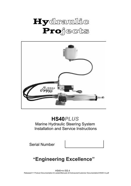
<strong>HS40</strong>PLUS<br />
Marine Hydraulic Steering System<br />
Installation and <strong>Service</strong> Instructions<br />
Serial Number<br />
“Engineering Excellence”<br />
<strong>HS40</strong>+m ISS.4<br />
Released\11 Product Documentation & Labels\Manuals & Enclosures\Customer Documentation\<strong>HS40</strong>+m.pdf
The information in this <strong>manual</strong> was, to the best of our knowledge,<br />
correct when it went to press and Hydraulic Projects Ltd cannot be liable<br />
for any inaccuracies or omissions. There may also be differences<br />
between the specifications in the <strong>manual</strong> and the product as a result of<br />
ongoing development for which we accept no liability.<br />
2
▪ Important Safety Information<br />
▪ Introduction<br />
▪ Description<br />
▪ Location<br />
▪ Dismounting the unit<br />
▪ Maintenance & <strong>Service</strong><br />
▪ Technical Data<br />
▪ Reservoir Preparation<br />
▪ Installation Considerations<br />
▪ Mounting Dimensions<br />
▪ Cylinder Dimensions<br />
Contents<br />
Page<br />
……………………………..4<br />
……………………………..5<br />
……………………………..6<br />
……………………………..7<br />
…………………………...8-9<br />
…………………………….10<br />
…………………………….11<br />
……………………...…12-13<br />
…………………………….14<br />
▪ Tiller Bolt<br />
▪ Pump Installation<br />
Reservoir Installation<br />
▪ Bleeding the System<br />
▪ Fault Finding<br />
▪ General Information<br />
▪ End of life Disposal<br />
▪ About Hydraulic Projects<br />
▪ Contact Details<br />
…………………………….15<br />
…………………………….16<br />
…………………………….17<br />
…………………………….18<br />
…………………………….19<br />
…………………………….20<br />
…………………………….21<br />
3
IMPORTANT SAFETY INFORMATION<br />
Failure to install and maintain this equipment in accordance with the instructions<br />
contained in this Manual could result in damage or injury.<br />
This equipment must be installed and maintained by a person who is<br />
qualified to do so. This equipment is only for use with marine<br />
Auto pilots within the limitations stated in the following pages.<br />
Auto pilot steering systems are navigational aids and the user must still<br />
maintain a permanent watch.<br />
This equipment meets the latest EMC (Electromagnetic Compatibility)<br />
standards required for use in the recreational marine environment. In order<br />
to ensure conformance and to prevent interference with electronic<br />
systems the unit must be properly bonded to earth and the<br />
supply cables screened.<br />
DO NOT FLASH TEST<br />
Beware of hot motor and solenoid components and the risk of<br />
entrapment from moving parts.<br />
4
INTRODUCTION<br />
Congratulations on the purchase of your Hydraulic Projects<br />
<strong>HS40</strong>PLUS Marine Hydraulic Steering System. It has been designed to<br />
give many years of trouble-free service providing the information and<br />
instructions contained within this <strong>manual</strong> are adhered to.<br />
DESCRIPTION<br />
'<strong>HS40</strong>PLUS' Hydraulic Steering Systems combine a hydraulic cylinder<br />
with clutch, reversing pump and reservoir in a compact installation.<br />
A solenoid clutch is engaged to extend or retract the rod. The cylinder<br />
and its mounting are protected by integral relief valves. Overall adjustment<br />
is incorporated into the stroke of the cylinder. Nominal cylinder<br />
size and pump flow are indicated on the rating plate. Check the voltage<br />
shown is correct for the output of your autopilot.<br />
Please do not disconnect any of the hoses, the system has been bled<br />
and tested prior to shipment.<br />
Ensure you read and understand the special reservoir instructions on<br />
page 10 before commencing installation.<br />
LOCATION<br />
For marine applications these systems are designed for 'under deck'<br />
installations only.<br />
Excessive temperature, vibration and fumes in the atmosphere can<br />
drastically reduce motor brush life.<br />
It must be mounted securely and on a surface that is able to withstand<br />
the high thrusts generated.<br />
As in common with other electrical equipment 5 contact with water and<br />
excessive humidity must be avoided.<br />
Any attitude of mounting may be used. Refer to the installation and<br />
technical data pages for further information.<br />
5
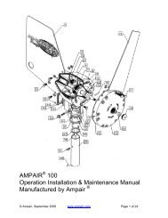
DISMOUNTING THE UNIT FROM ITS BASE<br />
The <strong>HS40</strong>PLUS cylinder features a quick-dismount base.<br />
To remove the base from the unit first take off the coil which is secured<br />
by a 17mm A/F nut. Next undo and remove the Allen screw ‘A’ and the<br />
retaining plate ‘B’ . Withdraw the mounting pin ‘C’ which will release the<br />
base.<br />
NOTE!<br />
The pin is a close engineered fit and if it proves difficult to remove take<br />
off the plastic cap from the head of the pin and insert screw ‘A’ into it.<br />
It will then be possible to withdraw the pin using a pair of pliers or grips.<br />
IMPORTANT!<br />
Avoid damage to the pin<br />
Assembly is a reversal of the removal process. Ensure the plastic cap<br />
is re-fitted to the pin upon completion.<br />
6
MAINTENANCE & SERVICE<br />
With a minimum of moving parts and top quality precision engineering<br />
the system will give many years of trouble free service if the following<br />
points are adhered to.<br />
▪ Keep the cylinder rod free from damage.<br />
▪ Avoid exposing the unit to salt water.<br />
Perform the following tasks on a regular basis:<br />
▪ Check the security of the mounting base and tiller bolt.<br />
▪ Lubricate the mounting pin & rod end - use only a good quality marine<br />
grease that is compatible with nitrile seals.<br />
▪ Examine all electrical connections.<br />
Brushes<br />
Inspect the motor brushes every 500 hours, or annually, for wear.<br />
Replacement motor brushes are available from your dealer. State the<br />
serial number of your unit when ordering.<br />
Be sure to clean out all loose carbon before fitting new brushes.<br />
If fluid has entered the motor, degrease the brush gear and commutator<br />
before running the unit, otherwise arcing will reduce brush life.<br />
Motor<br />
To remove the motor first turn the reservoir tap ’OFF’ to minimise oil<br />
loss. Undo and remove the two M8 bolts and washers and withdraw the<br />
motor. Be prepared to catch the small amount of oil that will drip from<br />
the seal housing when the motor is removed.<br />
When refitting ensure that the coupling is in place and aligned with the<br />
motor drive tang.<br />
Turn the reservoir tap back to ‘ON’ before operating.<br />
Seals<br />
Should service replacement seals be required, a kit is available from<br />
your nearest dealer under the following part code: <strong>HS40</strong>+sk.<br />
State the serial number of your unit when ordering.<br />
7
TECHNICAL DATA<br />
Cylinder<br />
Volume<br />
Stroke<br />
Adjustment<br />
Performance<br />
Maximum thrust (intermittent)<br />
Hard over time nominal <strong>HS40</strong>plus 10<br />
Hard over time nominal <strong>HS40</strong>plus 20<br />
Temperature rating minimum<br />
Temperature rating maximum<br />
Relief valve setting<br />
Back-drive at 12 sec Hard-over<br />
293cc (Nominal)<br />
254mm<br />
± 5mm<br />
(Refer page 17)<br />
675 kg<br />
13 sec<br />
9 sec<br />
-20ºc<br />
+65ºc<br />
62 bar<br />
7kg<br />
Electrical<br />
Motor voltage nominal<br />
12 or 24v DC<br />
Motor power<br />
100 watt<br />
Max current 12v 25% duty<br />
22.5 A<br />
Max current 24v 25% duty<br />
11.2 A<br />
Rotation<br />
Reversing<br />
Protection<br />
IP44<br />
Connection<br />
1m Flying Lead<br />
2 Core 2.5mm²<br />
Ignition protection BS EN 28846:1993<br />
Clutch Coil power continuous<br />
12 watt<br />
Connection DIN 43650<br />
Orientation<br />
Red lead Positive<br />
Cylinder Retracts<br />
Oil<br />
Recommended Q8 Dynobear 10<br />
Equivalent<br />
Mineral based hydraulic<br />
Min. ISO VG10<br />
Max. ISO VG40<br />
8
TECHNICAL DATA<br />
Ports<br />
Pump<br />
Cylinder<br />
Hoses<br />
Threads<br />
Material<br />
Type<br />
Length<br />
G1/4(BSP) parallel BS2779’73<br />
G1/4(BSP) parallel BS2779’73<br />
5/8-18 SAE female swivel<br />
Brass<br />
Marine Steering Hose<br />
1000 PSI Working Pressure<br />
5/16” I/D<br />
1m<br />
Materials<br />
Body Aluminium BS 1490<br />
Cylinder rod<br />
Chrome Plated Stainless Steel<br />
Seals<br />
Nitrile & PTFE<br />
Body Protection<br />
SP270<br />
System Weight<br />
11 kg Gross<br />
TYPICAL PERFORMANCE<br />
<strong>HS40</strong>PLUS<br />
<strong>HS40</strong>PLUS<br />
9
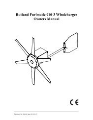
RESERVOIR PREPARATION<br />
IMPORTANT!<br />
The reservoir is fitted with a special cap with a breather hole that is<br />
sealed for transit and must be opened before operation.<br />
Do not attempt to move the cylinder rod before completing the<br />
following steps;<br />
1) Mount the reservoir on a bulkhead as far above the pump and<br />
cylinder as possible using both the mounting holes provided.<br />
2) Remove the transit screw and seal from the cap to open the<br />
breather. Retain for future use.<br />
3) Turn the tap to the ‘ON’ position.<br />
TRANSIT SCREW AND SEAL<br />
REMOVE BEFORE USE<br />
OFF<br />
ON<br />
10
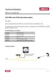
INSTALLATION DETAILS<br />
QUADRANT<br />
Typical installation for an<br />
8.4” ( 214mm) quadrant<br />
with total rudder angle of<br />
70deg.<br />
35°<br />
35°<br />
CONSIDERATIONS<br />
Ensure that cylinder<br />
rod movement is<br />
limited by the<br />
Steering end-stops<br />
and not by the<br />
actuator.<br />
574.80<br />
573.50<br />
Check that no part<br />
of the actuator fouls<br />
the structure of the<br />
vessel or quadrant<br />
throughout its full<br />
range if movement.<br />
Allow sufficient<br />
clearance for<br />
removal of the<br />
mounting pin<br />
(Ref. page 6).<br />
11
DIMENSIONS FOR CYLINDER MOUNTING FOOT<br />
(NOT TO SCALE)<br />
12
DIMENSIONS FOR PUMP MOUNTING FOOT<br />
(NOT TO SCALE<br />
NOTE ORIENTATION OF FOOT TO PUMP<br />
(REFER PAGE 16)<br />
88.9mm [3.5"]<br />
50.8mm [2"]<br />
13
CYLINDER DIMENSIONS<br />
264.60 MAX STROKE<br />
10° 10°<br />
16.0<br />
360 °<br />
MOVEMENT<br />
RUDDER REFERENCE / FEEDBACK OPTION<br />
441.2<br />
Ø12.0<br />
573.50<br />
705.8<br />
773<br />
10°<br />
14
TILLER BOLT<br />
56.0<br />
26.0<br />
The tiller bolt supplied is suitable for<br />
a quadrant thickness of 12 to 16mm.<br />
The tiller bolt mounting hole should<br />
be drilled Ø12.2 to 12.3mm.<br />
An application of Loctite 638 or<br />
equivalent where shown is<br />
recommended.<br />
16.0 MAX<br />
12.0 MIN<br />
Tighten the M12 nut to 27Nm<br />
MOUNTING FOOT<br />
The four M8 nuts, bolts and washers<br />
supplied are suitable for mounting<br />
the actuator onto a surface of<br />
between 12mm and 24mm thick<br />
Tighten the four M8 nuts to 17Nm<br />
COIL CONNECTIONS<br />
POSITIVE +<br />
NEGATIVE -<br />
15
FLYING LEADS<br />
2 CORE 2.5mm<br />
x 1 METRE LONG<br />
2<br />
PUMP INSTALLATION<br />
A<br />
R<br />
B<br />
Brush holder<br />
System Serial Number<br />
RESERVOIR INSTALLATION<br />
148.7<br />
2x 9.5<br />
55.3<br />
16
BLEEDING THE SYSTEM<br />
The system was filled and tested before despatch.<br />
Only use this procedure if air has entered the system or if it has been<br />
dismantled.<br />
KEEP CLEAR OF MOVING STEERING COMPONENTS<br />
AND LINKAGES AT ALL TIMES<br />
Before commencing ensure the oil and any storage containers are<br />
clean and free of contamination.<br />
Dispose of any waste oil responsibly.<br />
1) Make sure the reservoir tap is set to ‘ON’ (ref. page 10).<br />
2) Push the cylinder rod in so that it is fully retracted.<br />
3) Fill the reservoir then slacken, but do not disconnect the reservoir<br />
hoses from the cylinder. Re-tighten once the oil emerges from the<br />
fittings. Ref page 8 for recommended oil.<br />
4) Run the pump in order to direct flow to the cylinder ports.<br />
5) Energise the cylinder solenoid and slowly pull the cylinder rod out<br />
until it is fully extended. Observe the oil level in the reservoir and<br />
top up if necessary - Note that the oil level will rise when the rod is<br />
retracted and may overflow. Fully retract the rod, again observing<br />
the oil level in the reservoir and topping up as needed. Repeat until<br />
no more air can be seen to be rising into the reservoir and the<br />
pump takes over. De-energise the solenoid.<br />
6) To complete the bleeding, energise the cylinder solenoid again and<br />
run the pump in both directions to extend and retract the cylinder<br />
rod. Note that the cylinder may need <strong>manual</strong>ly assisting at first to<br />
purge any remaining air in the system.<br />
7) Top up the reservoir if necessary to the level indicated.<br />
17
FAULT FINDING<br />
Under no circumstances dismantle the unit unless it is certain that<br />
the fault is internal. Doing so will allow air into the cylinder,<br />
requiring the unit to be bled.<br />
Caution: Any damage to the cylinder rod will damage the seals and<br />
allow air into the cylinder / oil leaks.<br />
1) Motor does not run<br />
: check electrical connections.<br />
: check autopilot output.<br />
: check motor brushes.<br />
2) Motor runs, but erratic or no cylinder rod movement<br />
: check for clutch operation.<br />
: check for air in the cylinder -obviated by external oil loss.<br />
: check drive coupling (see page 7).<br />
3) Excessive noise from the pump<br />
: check the motor for damage.<br />
: check for air in the cylinder -obviated by external oil loss.<br />
: check drive coupling (see page 7).<br />
18
GENERAL INFORMATION<br />
Keep this <strong>manual</strong> in a safe place. Quote the model and serial<br />
numbers in all correspondence.<br />
Model Number:<br />
Serial Number:<br />
Date of Purchase:<br />
________________________________<br />
________________________________<br />
________________________________<br />
Dealer:<br />
________________________________<br />
________________________________<br />
________________________________<br />
________________________________<br />
________________________________<br />
________________________________<br />
END OF LIFE DISPOSAL<br />
Please dispose of End of Life items responsibly.<br />
In the event that you are unable to use your nearest local authority<br />
civic amenity sites to recycle, units can be returned to us at the address<br />
on the back cover.<br />
19
ABOUT HYDRAULIC PROJECTS<br />
Hydraulic Projects Ltd. was established in 1967 and designs and<br />
manufactures from its home in the South West of the United Kingdom.<br />
We offer a complete range of hydraulic marine steering components and<br />
hydraulic valves and ancillaries for the agricultural and mobile industries.<br />
Our in-house expertise and dedicated design team allow us to offer a<br />
unique service to our customers.<br />
ISO 9001 CERTIFICATION<br />
With ISO9001 certification for design and production and our reputation for<br />
technical support, you will find that Hy-Pro offers an ideal solution for all<br />
your hydraulic control requirements.<br />
Certificate No. 11935<br />
WEBSITE<br />
Please visit our website - www.hypro.co.uk for details of the entire range.<br />
20
CONTACT DETAILS<br />
Address :<br />
Hydraulic Projects Limited<br />
Dawlish Business Park<br />
Dawlish<br />
Devon<br />
EX7 0NH<br />
United Kingdom<br />
Telephone: +44 (0)1626 863634<br />
Fax : +44 (0)1626 866283<br />
Email :<br />
Web :<br />
enquiries@hypro.co.uk<br />
www.hypro.co.uk<br />
21