Betriebsanleitung "pulverisette 9"
Betriebsanleitung "pulverisette 9"
Betriebsanleitung "pulverisette 9"

You also want an ePaper? Increase the reach of your titles
YUMPU automatically turns print PDFs into web optimized ePapers that Google loves.
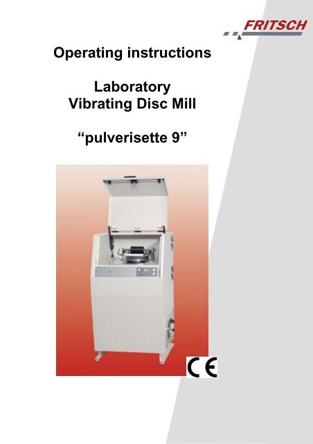
Operating instructions<br />
Laboratory<br />
Vibrating Disc Mill<br />
“<strong>pulverisette</strong> 9”
Fritsch GmbH<br />
Manufacturers of Laboratory Instruments<br />
Industriestraße 8<br />
D - 55743 Idar-Oberstein<br />
Phone: +49 (0)6784/ 70-0<br />
Fax: +49 (0)6784/ 70-11<br />
Email: info@fritsch.de<br />
URL: http://www.fritsch.de<br />
Fritsch GmbH, manufacturer of laboratory instruments was certified by the<br />
TÜV Zertifizierungsgemeinschaft e.V. on 21th November 2003.<br />
Based on an audit report Fritsch GmbH has been awarded the certificate<br />
of compliance to the requirements of DIN EN ISO 9001:2000<br />
Pursuant to the enclosed declaration of conformity to guidelines specified<br />
for the laboratory vibrating disc mill “<strong>pulverisette</strong> 9”, we are authorised to<br />
mark the instrument with the CE symbol.<br />
Instrument number 09.4000.00<br />
applies as of serial number 1001<br />
Ausgabe 05/2004 Index 004<br />
checked and released
Table of contents<br />
Page<br />
1 General Information / Introduction .........................................1<br />
1.1 Notes about Operating Instructions...................................................... 1<br />
1.2 Explanation of the symbols used on the machine and in the operating<br />
instructions ........................................................................................... 2<br />
1.3 Brief description of the machine ........................................................... 3<br />
1.3.1 Fields of application ......................................................................................... 3<br />
1.3.2 Method of operation ......................................................................................... 3<br />
1.4 Technical Data...................................................................................... 4<br />
2 Operating Safety ......................................................................5<br />
2.1 General Safety Instructions .................................................................. 5<br />
2.2 Operators.............................................................................................. 6<br />
2.3 Protective Devices................................................................................ 6<br />
2.3.1 Protective Devices ........................................................................................... 6<br />
2.3.2 Ways to open the hood .................................................................................... 6<br />
2.4 Danger Points....................................................................................... 7<br />
2.5 Electrical Safety.................................................................................... 7<br />
2.5.1 General information ......................................................................................... 7<br />
2.5.2 Protection against warm restart ....................................................................... 7<br />
2.5.3 Overload protection.......................................................................................... 7<br />
3 Installation ................................................................................8<br />
3.1 Unpacking............................................................................................. 8<br />
3.2 Transport .............................................................................................. 8<br />
3.3 Erection................................................................................................. 8<br />
3.4 Transportation Lock.............................................................................. 9<br />
3.5 Electrical Connection.......................................................................... 10<br />
4 Working with the vibrating disc mill.....................................11<br />
4.1 Function test ....................................................................................... 11<br />
4.2 Preparing a grinding operation ........................................................... 11<br />
4.2.1 Grinding sets.................................................................................................. 11<br />
4.2.2 Using the grinding sets .................................................................................. 11<br />
4.2.3 Dry Grinding................................................................................................... 12<br />
4.2.4 Wet Grinding (Grinding in Suspension).......................................................... 12<br />
4.2.5 Filling the grinding set .................................................................................... 12<br />
4.2.6 Fixing the grinding sets .................................................................................. 13<br />
4.2.7 Operating functions........................................................................................ 14<br />
4.2.8 Rotational speed (rpm) .................................................................................. 15<br />
4.3 Switching the vibrating disc mill on..................................................... 16<br />
4.4 Switching Off ...................................................................................... 16<br />
4.5 Cooling................................................................................................ 16<br />
4.6 Cleaning ............................................................................................. 16<br />
4.6.1 Grinding accessories ..................................................................................... 16<br />
4.6.2 Mill ................................................................................................................. 16<br />
5 Maintenance ...........................................................................17<br />
6 Warranty..................................................................................17<br />
7 Troubleshooting Checklist....................................................18<br />
<strong>pulverisette</strong> 9
1 General Information / Introduction<br />
1.1 Notes about Operating Instructions<br />
• Read the operating instructions carefully.<br />
• The laboratory vibrating disc mill “<strong>pulverisette</strong> 9“ has been referred<br />
to as vibrating disc mill below.<br />
• All operators must be familiar with the contents of the operating<br />
instructions.<br />
• Please follow the notes for your safety.<br />
• The laboratory vibrating disc mill has been designed with user<br />
safety in mind, however, other risks may not be ruled out. Follow<br />
the advices in these instructions to avoid risks to users.<br />
The symbols in the right hand margin highlight the risks described<br />
in the text.<br />
Symbols on the instrument warn against possible hazards or<br />
refer to this operating instructions. The symbols in the right<br />
hand margin (triangle with exclamation mark) indicates general<br />
hazards and refers to the operating instructions.<br />
• These operating instructions do not constitute a complete<br />
technical description. They describe only the details required<br />
for safe operation and maintenance for usage under normal<br />
conditions.<br />
• The copyright to these technical documents is the property of<br />
Fritsch GmbH, Manufacturers of Laboratory Instruments.<br />
• These operating instructions are not to be reprinted or copied<br />
without the express approval of Fritsch GmbH.<br />
<strong>pulverisette</strong> 9 Page 1
1.2 Explanation of the symbols used on the machine<br />
and in the operating instructions<br />
Attention!<br />
Warning against danger spot<br />
Observe operating instructions<br />
Attention! Mains voltage<br />
Attention! Hazard of explosion<br />
Attention! Hot surface<br />
Attention! Inflammable substances<br />
Wear protective gloves!<br />
Wear safety goggles!<br />
Do not step below lifted load!<br />
Do not spray with water!<br />
Warning against hand injury!<br />
<strong>pulverisette</strong> 9 Page 2
1.3 Brief description of the machine<br />
1.3.1 Fields of application<br />
The vibrating disc mill is a mill for quick and set-wise fine dry and wet<br />
grinding of brittle to very hard material samples e.g. in the fields of mining<br />
(coal, ores, minerals), metallurgy (slags, casting samples), ceramic<br />
industry, cement and building material industry, agriculture and forestry.<br />
1.3.2 Method of operation<br />
The vibrating disc mill operates on the principle of a vibrating mill i.e. the<br />
griding set is fixed on a freely vibrating structure and the griding media<br />
(disc and rings) inside the grinding set are accelerated by centrifugal<br />
force and pulverise the grinding material by means of impact and friction.<br />
The grinding sets (made of hardened steel, hard metal tungsten carbide<br />
or agate) are closed by means of sealing inserted to prevent losses during<br />
wet or dry grinding operations.<br />
The powerful drive motor allows different rotational speeds to choose<br />
from 600 - 1100 rpm in steps of 50 rpm. This way the grinding effect can<br />
be customsed to the practical requirements. While using the grinding set<br />
sensitive to impact made of agate, speeds higher than 750 rpm are<br />
automatically limited to 750 rpm. (Also see chapter 1.4 Technical Data)<br />
The grinding set made of agate can be operated at a maximum<br />
speed of 750 rpm only (danger of damage to the grinding set).<br />
<strong>pulverisette</strong> 9 Page 3
1.4 Technical Data<br />
Dimensions and Weight<br />
Dimensions: 1174x717x656mm (Height x Width x Depth)<br />
Weight: 260kg (without grinding set)<br />
Operating Noise<br />
On an average, the noise level is 81 dB (A). This value has been<br />
measured in a soundproof room using a 250 ml steel griding set<br />
at 1100 rpm.<br />
The value can change depending on the gridning set and grinding<br />
material used as well as the speed settings. Also the size and<br />
the characteristics of the walls, floor and ceiling of the room affect<br />
the noise level.<br />
Voltage<br />
The vibating disc mill sets to the mains voltage (100-240 V)<br />
automatically. Operating the machine on other voltage is not<br />
permitted.<br />
Current consumption<br />
Max. 15A at 110V mains voltage<br />
Max. 14A at 115V mains voltage<br />
Max. 8A at 230V mains voltage<br />
Max. 8A at 240V mains voltage<br />
Power consumption<br />
Max. 1500W at 100V mains voltage<br />
Max. 1610W at 115V mains voltage<br />
Max. 1840W at 230V mains voltage<br />
Max. 1920W at 240V mains voltage<br />
Electrical fuses in the control unit<br />
(see Chapter 7 Troubleshooting Checklist)<br />
• Automatic safety fuse 15 A (inserting box on the side)<br />
Material<br />
• The volume of the material depends on the size of the grinding<br />
set used and is maximum 50, 100 or 250 ml.<br />
• The volume of material also depends on the type and size of<br />
griding set and is maximum 7 or 12 mm.<br />
Final Fineness<br />
Up to 10-20µm<br />
<strong>pulverisette</strong> 9 Page 4
2 Operating Safety<br />
2.1 General Safety Instructions<br />
• Read the operating instructions carefully.<br />
• The operator must be familiar with the contents of the operating<br />
instructions.<br />
For this purpose, always keep the operating instructions within<br />
easy reach.<br />
• Do not remove the instruction labels.<br />
• Do not switch off security devices.<br />
• Arbitrary changes to the instrument undertaken by the user<br />
may result in cancellation of conformity to European guidelines<br />
as declared by Fritsch.<br />
• The vibrating disc mill is intended exclusively for tasks described<br />
in Section 1.3.1 Fields of application.<br />
Using the instrument improperly or for any other purpose shall<br />
be deemed as contravention of its intended use. The manufacturer<br />
shall not be liable for damages resulting from such<br />
use.<br />
• The user is advised to comply with the generally applicable legal<br />
and other regulations, supplementing the operating instructions,<br />
for prevention of accidents and environmental protection.<br />
• When using the instrument wear handgloves.<br />
After a grinding operation, the grinding set can be very hot.<br />
• Wear protective glasses!<br />
During wet grinding, the high temperature could lead to positive<br />
pressure. Risk of splashing.<br />
• If the noise level reaches or exceeds 85dB (A), wear ear protection<br />
to prevent hearing damage.<br />
• The MAK values of the valid safety instructions must be observed<br />
and if necessary, ventilation should be provided or the<br />
machine should be operated under an outlet.<br />
• When oxidizable materials such as metals, organic materials,<br />
wood, coal, plastic, etc. are ground or sieved, the risk of spontaneous<br />
ignition (dust explosion) exists whenever the fine particles<br />
exceed a specific percentage. While such materials are<br />
being ground, it is therefore necessary to take special safety<br />
precautions (e.g. wet grinding) and a specialist must supervise<br />
the work.<br />
• The design of the vibrating disc mill is not protected against<br />
explosions; hence it is not suitable for grinding explosive materials.<br />
• Do not operate the vibrating disc mill in several quick successions.<br />
Mostly grinding time of few minutes is sufficient; exceeding<br />
this can cause overheating or damage to the grinding<br />
set.<br />
<strong>pulverisette</strong> 9 Page 5
2.2 Operators<br />
• Only authorised persons may operate the vibrating disc mill<br />
and trained personnel may undertake maintenance and repair<br />
work on it.<br />
• Persons suffering from any illness or under the influence of<br />
medication, drugs, alcohol or physical fatigue, may not be allowed<br />
to operate the vibrating disc mill.<br />
2.3 Protective Devices<br />
2.3.1 Protective Devices<br />
• Protective devices should be used for the intended purpose<br />
and must not be made unserviceable or removed.<br />
• All protective devices should be regularly checked for completeness<br />
and to ensure that they are functioning correctly.<br />
See chapter 5 Maintenance.<br />
• The vibratig disc mill is equipped with a safety locking system<br />
with a protective function for the operating personnel.<br />
During operation, this device locks the hood and prevents the<br />
vibrating disc mill from operating when the hood is open:<br />
- The hood cannot be opened during operation.<br />
- The machine does not start if the hood is open.<br />
2.3.2 Ways to open the hood<br />
• As long as the vibrating disc mill is disconnected from the<br />
mains, the hood remains locked. Connect the vibrating disc<br />
mill to the mains to open the hood.<br />
• The hood is locked when the vibrating disc mill is in operation.<br />
To open the hood, press the STOP key on the control<br />
panel. The hood can be opened once the motor comes to a<br />
standstill.<br />
• Auxiliary unlocking:<br />
If the machine cannot be connected to the mains or there is a<br />
power outage, the hood can be opened with a tool provided<br />
for this purpose.<br />
Unscrew the covering plate on the left side of the vibrating<br />
disc mill. Insert the triangular key through the opening and<br />
turn the switch in the anti-clockwise direction. Caution: Make<br />
only a quarter turn till a limit stop is felt. Do not attempt to turn<br />
beyond the limit stop as this may damage the locking system.<br />
Now the hood can be opened, however, no operation is possible.<br />
The machine can be operated only on retunring the<br />
switch to its original position and closing the hood.<br />
The triangular key is included in the original packing inside<br />
the grinding chamber.<br />
<strong>pulverisette</strong> 9 Page 6
2.4 Danger Points<br />
• Danger of impact when the hood is opened.<br />
• Danger of crushing when the hood is being closed<br />
• Danger of bruises at the fixing bracket on the grinding set<br />
2.5 Electrical Safety<br />
2.5.1 General information<br />
• Once the STOP key is pressed, the vibrating disc mill stops<br />
running. The hood can be opened when the motor comes to<br />
a standstill.<br />
• When using the grinding set made of agate, the speed is<br />
automatically limited to 750 rpm.<br />
• Unplug the instrument from the mains, if the mill is not going<br />
to be used for a considerable period of time (e.g. overnight).<br />
2.5.2 Protection against warm restart<br />
In case of power outage during operation or on disconnecting from the<br />
mains supply, the hood gets locked. On resumption of power, the hood<br />
locking is released again.<br />
As a safeguard, the vibrating disc mill requires manual restart.<br />
2.5.3 Overload protection<br />
In case the vibrating disc mill is overloaded, a motor current monitoring<br />
system reduces the speed automatically and in case of a blockage the<br />
drive cuts off directly.<br />
<strong>pulverisette</strong> 9 Page 7
3 Installation<br />
3.1 Unpacking<br />
• Remove the pins meant for holding the hood onto the transportation<br />
pallet. The hood is the wooden box put over the<br />
transportation pallet.<br />
• Lift the hood from the transportation pallet.<br />
• Compare the contents of the consignment with your order.<br />
3.2 Transport<br />
• For transportation on the pallet use a forklift or lift.<br />
Do not step underneath the transportation pallet.<br />
• For transportation, use a suitable lifting device<br />
equipped with a hoist.<br />
3.3 Erection<br />
• Lift the vibrating disc mill from the transportation pallet. The<br />
mill stands on two U rails and it can be lifted with a forklift.<br />
• Place the vibrating disc mill indoors on an even and stable<br />
base. The instrument need not be fixed to the base.<br />
Operating the vibrating disc mill when it is standing on the transportation<br />
pallet is not permissible.<br />
• Make sure that the vibrating disc mill is easily accessible.<br />
• The ambient temperature must be between 0 and 40°C.<br />
• If the floor surface is uneven, adjust the machine feet to<br />
achieve an absolutely vertical and stable position.<br />
Key width 19<br />
<strong>pulverisette</strong> 9 Page 8
3.4 Transportation Lock<br />
Attention!!!<br />
Please remove all parts of the transportation lock before putting the instrument<br />
into operation.<br />
1. Please remove the three red transportation locks by using the<br />
allen key delivered with the instrument.<br />
2. Then please turn the included 3 white plastic plugs into the<br />
boreholes of the transportation lock.<br />
3. Store the transportation lock carefully.<br />
<strong>pulverisette</strong> 9 Page 9
3.5 Electrical Connection<br />
• Before making the connection, compare the voltage and current<br />
values shown on the nameplate with the values of the<br />
mains supply to which the instrument is to be connected.<br />
• N.B.: Operate the vibrating disc mill only when the grinding<br />
set is in place.<br />
• Connect the included cable to the socket on the right side.<br />
• Power up the main switch on the front plate. After a few seconds<br />
the automatic unlocking system releases the hood.<br />
• Turn the lever 90° to the left, open the hood after it is automatically<br />
unlocked and remove the red transportation clamps.<br />
(page 2 service manual)<br />
• Now you can load the mill and start it as described in Section<br />
4.2.6.<br />
<strong>pulverisette</strong> 9 Page 10
4 Working with the vibrating disc mill<br />
4.1 Function test<br />
• Connect the appliance to the power supply.<br />
• Open the hood.<br />
• Fill the grinding set and fix it.<br />
(see Section 4.2 Preparing a grinding operation)<br />
Operate the machine only when the grinding set is fixed and filled<br />
with the grinding material.<br />
• Close the hood and turn the lever 90° to the right.<br />
• Select the speed, grinding duration, pause times and repetitions<br />
in advance. In most cases, a grinding duration of 2-4<br />
minutes is sufficient to achieve satisfactory results. Prolonged<br />
grinding does not yield any lesser final fineness. If dry grinding<br />
is used for long time, the grinding material gets baked<br />
onto the grinding media making it difficult to clean.<br />
• Press the START key on the control panel.<br />
• The hood is locked and the vibrating disc mill begins to run.<br />
• Press the STOP key on the control panel.<br />
• Once the motor comes to a standstill, the hood can be<br />
opened.<br />
4.2 Preparing a grinding operation<br />
4.2.1 Grinding sets<br />
Grinding<br />
vessel volume<br />
Grinding<br />
media<br />
50 ml 100 ml 250 ml<br />
1 disc 1 disc,<br />
1 ring<br />
1 disc,<br />
2 rings<br />
4.2.2 Using the grinding sets<br />
Grinding container<br />
50, 100 and 250 ml........................ Hardened steel<br />
50, 100 and 250 ml........................ Tungsten carbide<br />
50 and 100 ml................................ Agate (operate at 750 rpm only)<br />
Never mix grinding media and grinding sets of different materials.<br />
Always place all discs and rings as per the above table.<br />
In case of steel grinding sets, always place the outer ring with the<br />
outer radius pointing below. Inside the grinding vessel too, there is<br />
a radius at the bottom.<br />
<strong>pulverisette</strong> 9 Page 11
4.2.3 Dry Grinding<br />
Surface forces predominate in case of particle size of less than approx.<br />
20 µm and the material will start to "stick".<br />
Further dry grinding can be achieved if surface-active substances are<br />
added to the material.<br />
Examples (maximum quantity to be added in % by mass)<br />
• Stearic acid 2-3%<br />
• Aerosil (highly dispersible silicic acid) 0.5-2%<br />
• Quarry sand 2 %<br />
• Glass powder 2 %<br />
4.2.4 Wet Grinding (Grinding in Suspension)<br />
When shifting to grinding operation in suspension you can add liquid<br />
agents with high boiling point (> 80°C) and less vapour pressure.<br />
With wet grinding you can achieve higher grades of final fineness.<br />
When using wet grinding, high pressure and temperatures may result in<br />
the grinding vessel. Exercise caution while opening the eccenteric lever,<br />
as hot vapours may be released at high pressure. Open the lever slowly,<br />
wear protective goggles or, allow the grinding set to cool down inside the<br />
machine.<br />
Do not use any easily inflammable or combustible fluids such as<br />
ketones and petroleum.<br />
4.2.5 Filling the grinding set<br />
Maximum filling quantities are as per the specified volumes (50, 100 or<br />
250 ml).<br />
Minimum filling quantities are 30% of the specified volumes.<br />
4. Place all grinding media with the rounded edge pointing<br />
downwards ino the grinding vessel.<br />
5. Put the grinding material between the grinding media into the<br />
grinding vessel.<br />
6. If necessary, clean the edge of grinding vessel to remove<br />
grinding material as well as the sealing ring on the lid.<br />
7. Place the lid on top.<br />
<strong>pulverisette</strong> 9 Page 12
4.2.6 Fixing the grinding sets<br />
Check the complete fixing device and the bow lever before each grinding<br />
operation for firm grip.<br />
Insertion<br />
1. Insert the filled grinding set in front into the takeup groove<br />
and turn until it is fixed securely into the groove. The lever<br />
must be turned fully backwards.<br />
2. Hold the grinding set in front at the handles and slide it up to<br />
the limit stop towards the back below the eccentric roller.<br />
Caution!<br />
Danger of bruises between the handle and the bows on<br />
the side of the fixture.<br />
3. Hold the bow lever directly over the point of rotation and turn<br />
towards the front.<br />
Caution!<br />
Danger of squeezing between the bow lever handle and<br />
the top edge of the housing.<br />
4. Hold the bow lever at the handle in front and press it downwards<br />
till the limit stop. The eccentric cam is moved beyond<br />
the lowest point and it fixes the grinding set.<br />
5. A small lever on the right side of bow lever presses a safety<br />
switch that releases the machine, only when the fixutre is activated.<br />
If the fixture becomes loose during the grinding operation,<br />
the machine should be switched off immediately. The<br />
machine cannot be switched on again without the grinding<br />
set.<br />
6. Check:<br />
Certain amount of force is necessary to activate the fixing<br />
lever properly.<br />
7. If the bow lever cannot be pressed downwards or can be<br />
pressed only with great difficulty, the grinding set is not fixed<br />
properly into the rear groove. Pull out the grinding set once<br />
again and press it backwards till the limit stop.<br />
8. After the grinding operation, hold the bow lever on the handle<br />
and pull out carefully in the upward direction. The grinding set<br />
may be very hot and there may be excessive pressure build<br />
up in the grinding set.<br />
Caution! Wear protective goggles.<br />
<strong>pulverisette</strong> 9 Page 13
9. Thereafter, hold the bow lever directly over the point of rotation<br />
and shift it backwards till the limit stop.<br />
Caution!!!<br />
Danger of bruises between the bow lever handle and the<br />
top edge of the housing.<br />
10. The grinding set is pressed by the ball press pieces upwards<br />
out of the groove and it can be drawn to the front towards the<br />
body by holding the handles.<br />
11. It may happen that the grinding set is stuck to the rubber<br />
plate and hence cannot be moved to the front. In such a<br />
situation, slide a thin but rigid object (e.g. a knife) between<br />
the rubber plate and grinding set and release the rubber<br />
plate. Apply some talcum powder to the rubber plate (bicycle<br />
or vehicle accessory) to minimize adhesion. This should be<br />
done once a week.<br />
4.2.7 Operating functions<br />
Using the Timer functions, the grinding process can be controlled precisely<br />
up to seconds. Similarly, repeatable cycles can be set for grinding<br />
operations and passive cooling phases or can also be set in combination<br />
with REVERSE for rotation in the opposite direction.<br />
Functions:<br />
Speed: The drive motor speed (= vibrating frequency of the grinding set)<br />
is between 600 and 1100 rpm that can be set in steps of 50. The speed<br />
is constantly regulated at close ranges of (+/- 1%), allowing grinding<br />
efficiency to be reproduced in an excellent manner. Especially, in case<br />
of heavy grinding sets, it might not be possible to achieve high speeds<br />
due to drive overloading. This is indicated by a blinking decimal point in<br />
the Speed display below on the right side.<br />
Optimize Speed: After activating the key, an LED message is returned,<br />
the display shows the speed indicating 'Opt.' This function allows the<br />
user to apply more power to the grinding material. In this, the speed is<br />
increased to the maximum limit of drive performance, however, not beyond<br />
1300 rpm.<br />
<strong>pulverisette</strong> 9 Page 14
Timer Milling: Here the grinding duration is determined in settings of<br />
minutes and seconds. 10 sec are the minimum and the maximum possible<br />
is 99 min and 59 sec. Time 0 min 0 sec -> starting NOT possible.<br />
Timer Pause: Here in case of extended grinding duration the duration of<br />
the cooling pause is determined in combination with REPETITIONS. A<br />
maximum of 99 min is possible, 00 means no pause.<br />
N.B.:<br />
During the pause, the hood remains locked and the machine fans<br />
run at maximum cooling level. Pause 'active' is indicated by a blinking<br />
dot in the Pause display.<br />
Repetitions: The combination of entered grinding and pause times or<br />
REVERSE setting is repeated at the number entered here. Basically, the<br />
programmed operation cycle runs first followed by the number of repetitions.<br />
Example 1:<br />
Time Milling = 10min, Time Pause = 1 min, Repetitions = 5 total 60<br />
min grinding, 5 min pause (last pause was ignored) .<br />
Example 2:<br />
Time Milling = 5 min, Pause = 2 min, Repetitions = 5, Reverse active <br />
total 30 min grinding, 10 min pause and change in the direction of the<br />
rotation after each cycle<br />
Example 3:<br />
Time Milling = 1 min, Pause = 0 min, Repetitions = 19, Reverse active<br />
total 20 min grinding, no pause and change in the direction of the<br />
rotation after every minute.<br />
Further user instructions:<br />
‣ Display 'Hood' in the Speed display = Hood is not closed or<br />
the lever is not locked.<br />
‣ Display 'CLA.' in the Speed display = Grip is not closed.<br />
‣ On activating the START key, the setting parameters will be<br />
saved. These settings will be available on powering up.<br />
4.2.8 Rotational speed (rpm)<br />
A higher RPM increases the fineness and decreases the duration of<br />
grinding.<br />
A lower RPM is easy on the grinding material and the grinding tools.<br />
RPM is between 600 and 1100 rpm and can be selected in steps of 50<br />
rpm.<br />
<strong>pulverisette</strong> 9 Page 15
4.3 Switching the vibrating disc mill on<br />
The vibrating disc mill can be switched on after fixing the filled grinding<br />
set securely and closing the hood:<br />
• Select the grinding time<br />
• Press START on the control panel.<br />
• The hood gets locked and the vibrating disc mill begins to run.<br />
• As the countdown starts, the remaining time is displayed.<br />
Watch for overheating of grinding material and grinding set; if running<br />
time is longer than normal, provide for intervals to allow the<br />
machine to cool down.<br />
4.4 Switching Off<br />
• Press STOP on the control panel.<br />
• Once the motor comes to a standstill, the hood is unlocked<br />
and it can be opened.<br />
• If the machine is not in use for a long period, switch off the<br />
mains.<br />
4.5 Cooling<br />
Before a rerun, allow the grinding set to cool down to room temperature.<br />
4.6 Cleaning<br />
4.6.1 Grinding accessories<br />
• Clean the grinding vessel and grinding media after every use:<br />
E.g. brush to clean the items under running water with commonly<br />
used cleaning agents.<br />
• Fill the grinding bowl with some sand (1/3 of the utility volume)<br />
and water and allow it to run for 2 to 3 minutes (properly<br />
fixed) in the vibrating disc mill.<br />
• After cleaning, dry the grinding vessel and griding media well.<br />
• When sterilising the grinding bowl and grinding balls in the<br />
drying chamber, heat only to 250°C.<br />
Attention!!<br />
Do not heat agate grinding parts above 110°C. Cool them slowly and<br />
carefully.<br />
Agate parts must never be heated in the microwave (they heat up too<br />
rapidly).<br />
They must never be subjected to temperature shocks, such shocks may<br />
destroy the parts They burst apart explosively.<br />
4.6.2 Mill<br />
• The vibrating disc mill can be wiped clean with a wet cloth<br />
when the machine in switched off.<br />
Do not allow any liquids to seep into the machine.<br />
<strong>pulverisette</strong> 9 Page 16
5 Maintenance<br />
Before commencing maintenance work, disconnect the mains plug<br />
and secure the machine against being switched on again unintentionally!<br />
If maintenance work is in progress, this should be indicated with a<br />
warning sign.<br />
Maintenance work should be carried out only by qualified personnel.<br />
Switch on the safety devices after maintenance and/or repair work<br />
is over.<br />
Cleaning at regular intervals is of utmost importance for maintaining the<br />
vibrating disc in good condition.<br />
Functional<br />
part<br />
Feed Test Maintenance interval<br />
Safety lock Locking the hood Check that the closed hood is firmly Before each use<br />
held when the main switch is off.<br />
Fixture system<br />
Tighten the grinding Check for firm grip.<br />
Before each use<br />
set securely.<br />
Rubber plate<br />
below the<br />
grinding set<br />
Ensure firm grip for<br />
the grinding set<br />
If grinding set is sticking to the rubber<br />
plate, apply talcum to the rubber plate.<br />
Every week or after<br />
every 10 hours<br />
of operation<br />
Fixture system<br />
Fixture system<br />
Tighten the grinding<br />
set securely.<br />
Tighten the grinding<br />
set securely.<br />
Grease the joints lightly with machine<br />
oil.<br />
Check both the bearing bushings (DUbushings)<br />
of the eccentric shaft. Replace<br />
themi if the bearing bushings are<br />
deformed.<br />
6 Warranty<br />
The warranty card accompanying this instrument must be returned to the<br />
manufacturer, duly filled out, in order for the warranty to become effective.<br />
The option of online registration is available. For further information,<br />
please refer to your warranty card or visit our Homepage<br />
http://www.fritsch.de<br />
We, Fritsch GmbH, Germany, our application technology laboratory and<br />
our agent in your country will gladly provide advice and assistance with<br />
this instrument.<br />
Always include the serial number found on the nameplate with any queries.<br />
Every week or after<br />
every 10 hours<br />
of operation<br />
after every 100<br />
hours of operation<br />
<strong>pulverisette</strong> 9 Page 17
7 Troubleshooting Checklist<br />
Before commencing maintenance work, disconnect the mains plug<br />
and secure the machine against being switched on again unintentionally!<br />
If maintenance work is in progress, this should be indicated with a<br />
warning sign.<br />
Switch on the safety devices after maintenance and/or repair work<br />
is over.<br />
Malfunction Possible cause Elimination of error<br />
Instrument is<br />
not working<br />
Power is disconnected<br />
Timer on 0<br />
Insert the power plug<br />
Set time<br />
Automatic safety fuse Reset the automatic<br />
safety fuse on the side<br />
plate<br />
Grinding set<br />
sticks to rubber<br />
plate<br />
Grinding material<br />
spills out<br />
Unsteady<br />
functioning<br />
with heavy<br />
vibrations<br />
Grinding operation is<br />
too long, grinding set<br />
is overheated<br />
Sealing on the lid of<br />
grinding set is defective<br />
or soiled<br />
Suspension spring of<br />
take up is broken<br />
Apply talcum to rubber<br />
plate or replace it<br />
Clean the sealing and<br />
contact suface on the<br />
grinding vessel or replace<br />
sealing ring<br />
Replace spring<br />
<strong>pulverisette</strong> 9 Page 18