"JP" SERIES FILTER SYSTEMS OPERATIONS MANUAL - Jordair ...
"JP" SERIES FILTER SYSTEMS OPERATIONS MANUAL - Jordair ...
"JP" SERIES FILTER SYSTEMS OPERATIONS MANUAL - Jordair ...

You also want an ePaper? Increase the reach of your titles
YUMPU automatically turns print PDFs into web optimized ePapers that Google loves.
“JBP” <strong>SERIES</strong> <strong>FILTER</strong> <strong>SYSTEMS</strong><br />
<strong>OPERATIONS</strong> <strong>MANUAL</strong><br />
101-7950 Huston Rd.<br />
Delta, BC V4G 1C2 Canada<br />
Website: www.jordair.ca<br />
JORDAIR – “RELIABILITY & SAFETY” - BAUER Phone: 1-604-940-8101<br />
Fax: 1-604-940-8131<br />
Email: info@jordair.ca<br />
Doc. <strong>Jordair</strong> COMPRESSOR-<strong>MANUAL</strong>-2013
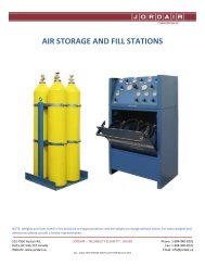
WARNING!<br />
High pressure air has Tremendous Kinetic Energy;<br />
Shut off valves on air storage cylinders, fill station and any other air control panels.<br />
Depressurize system slowly before starting any service work.<br />
This reduces risk of Explosive Venting.<br />
General instructions for filter maintenance<br />
– Dry inside of filter housing with a clean cloth before installing new cartridge and check for corrosion.<br />
– Lubricate threads and o-rings as well as threads on filter chamber.<br />
– Observe number of operating hours to ensure compliance with service intervals.<br />
– Change cartridge before returning to service any compressor that has out of service for more than six months.<br />
– Leave cartridge in the filter chamber as long as the unit is out of service, in order to absorb moisture in the filter system.<br />
– Keep all condensate drain-valves and shut-off valves closed. Maintain a minimum pressure of approximately 50 to 80 barg<br />
(700 to 1000 psig) within the system to prevent moisture entering the filter system.<br />
Maintenance intervals<br />
• Replace cartridges every six months or according to Securus indicator.<br />
• All o-rings and back-up rings are to be changed with filters; lower filter cap o-ring and back-up ring changed annually.<br />
• Service check valve annually; replace kit.<br />
• Service auto drain annually; replace kit.<br />
• PMV serviced annually replace kit.<br />
• See respective section for complete procedures.<br />
All rights reserved. No part of this publication may be reproduced, distributed, or transmitted in any form or by any means, or stored in a database or<br />
retrieval system, without the prior written permission of <strong>Jordair</strong> Compressors Ltd.<br />
101-7950 Huston Rd.<br />
Delta, BC V4G 1C2 Canada<br />
Website: www.jordair.ca<br />
JORDAIR – “RELIABILITY & SAFETY” - BAUER Phone: 1-604-940-8101<br />
Fax: 1-604-940-8131<br />
Email: info@jordair.ca<br />
Doc. <strong>FILTER</strong>-<strong>SYSTEMS</strong>-<strong>MANUAL</strong>-2013<br />
1
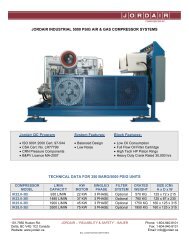
QTY. DESCRIPTION PART NO.<br />
AD-101 1 Autodrain, Single Bank J-BD-1-5<br />
CH-101 1 Check Valve J-5CV-P-4<br />
EB-101 1 Electrical Box / System see Fig. 2<br />
FIL-101 1 Filter Chamber, Drying JBF-6300-32<br />
FIL-102 1 Filter Chamber, Drying JBF-6300-32<br />
FIL-103 1 Filter Chamber, Purifying JBF-6300-32S<br />
PI-101 1 Pressure Gauge J-0-6000<br />
QTY. DESCRIPTION PART NO.<br />
PMV-101 1 Pressure Maintaining Valve J-PMV-6000<br />
PRV-101 1 Pressure Relief Valve 3305-A01-KC3750<br />
SEC-101 1 Securus Monitor N15096<br />
SEP-101 1 Oil / Water Separator JS-6300-4.5-18-1008<br />
SV-101 1 Solenoid Valve 7131KBN2BR00N0C111P3<br />
VA-101 1 Drain Valve 11430<br />
VA-102 1 Drain Valve 11430<br />
101-7950 Huston Rd.<br />
Delta, BC V4G 1C2 Canada<br />
Website: www.jordair.ca<br />
JORDAIR – “RELIABILITY & SAFETY” - BAUER Phone: 1-604-940-8101<br />
Fax: 1-604-940-8131<br />
Email: info@jordair.ca<br />
Doc. <strong>FILTER</strong>-<strong>SYSTEMS</strong>-<strong>MANUAL</strong>-2013<br />
2
101-7950 Huston Rd.<br />
Delta, BC V4G 1C2 Canada<br />
Website: www.jordair.ca<br />
JORDAIR – “RELIABILITY & SAFETY” - BAUER Phone: 1-604-940-8101<br />
Fax: 1-604-940-8131<br />
Email: info@jordair.ca<br />
Doc. <strong>FILTER</strong>-<strong>SYSTEMS</strong>-<strong>MANUAL</strong>-2013<br />
3
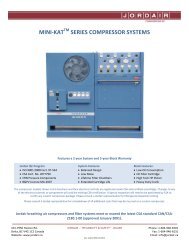
330S-A01-KC3750 Relief valve<br />
Relief valve needs to be tested, set and certified to the<br />
operating pressure and to be replaced as a complete unit if<br />
found defective.<br />
330S-A01-KC3750 RELIEF VALVE<br />
ITEM QTY MATERIAL DESCRIPTION<br />
1 1 SS SA479-304 Nozzle<br />
2 1 Teflon® O-ring<br />
3 1 SB211 Alloy 2024 T3511 Body Aluminum<br />
4 1 SS A313-302 Bottom Spring<br />
5 1 SS A582-303 Bottom Disc<br />
6 1 Aluminum B211 Alloy 2024 T351 Bottom Spring Step<br />
7 1 Kynar® Insert<br />
8 1 Teflon® Seal<br />
9 1 SS A582-303 Top Disc<br />
10 1 Steel A231 Aluminum Coated Top Spring<br />
11 1 SB-211 Alloy 6061-T6 Cap Aluminum<br />
12 1 Aluminum B211 Alloy 2024 T351 Top Spring Step<br />
13 1 SS A582-303 Compression Screw<br />
14 1 SS A582-303 Jam Nut<br />
101-7950 Huston Rd.<br />
Delta, BC V4G 1C2 Canada<br />
Website: www.jordair.ca<br />
JORDAIR – “RELIABILITY & SAFETY” - BAUER Phone: 1-604-940-8101<br />
Fax: 1-604-940-8131<br />
Email: info@jordair.ca<br />
Doc. <strong>FILTER</strong>-<strong>SYSTEMS</strong>-<strong>MANUAL</strong>-2013<br />
4
SERVICE OF THE SEPARATOR NON-RETURN VALVE<br />
• The separator non-return valve is located on the outlet of<br />
the oil and water separator.<br />
• Ensure that the separator is vented of all pressure and the<br />
filter towers are also depressurized.<br />
• Remove the valve from the system and remove the tube<br />
connecting fittings so that the internal poppet can be<br />
removed.<br />
• Clean and check the valve for any seat damage.<br />
• The poppet assembly is to be replaced annually, the<br />
complete valve is to be replaced if there is any leakage or<br />
seat body wear or damage noticed during inspection.<br />
• Thoroughly clean the body of all old lubricant or oil<br />
emulsions.<br />
• Lubricate all contact surfaces in the body and install the<br />
poppet with the new seals.<br />
• Install the valve in the system while ensuring the valve is<br />
oriented in the correct direction of the airflow.<br />
SEPARATOR NON-RETURN VALVE<br />
ITEM QTY PART NO. DESCRIPTION<br />
1 1 J-03-P017 Body<br />
2 1 J-2-009 O-ring<br />
3 1 J-03-P016 Sleeve<br />
4 1 J-03-P013 Spindle<br />
5 1 J-5CV-P-4-S Spring<br />
6 1 J-03-P014 Seat<br />
J-CVP-5K Kit includes items 2,3,4,5,6<br />
101-7950 Huston Rd.<br />
Delta, BC V4G 1C2 Canada<br />
Website: www.jordair.ca<br />
JORDAIR – “RELIABILITY & SAFETY” - BAUER Phone: 1-604-940-8101<br />
Fax: 1-604-940-8131<br />
Email: info@jordair.ca<br />
Doc. <strong>FILTER</strong>-<strong>SYSTEMS</strong>-<strong>MANUAL</strong>-2013<br />
5
SERVICE OF THE OIL AND WATER SEPARATOR<br />
• Disconnect the inlet and outlet pressure lines so that<br />
the separator top cap can be removed for service of the<br />
filter element.<br />
• Carefully remove the top cap from the barrel by turning<br />
counter-clockwise with the filter wrench (<strong>Jordair</strong> part #<br />
J-FW-FD).<br />
• Inspect the interior of the barrel chamber, O-<br />
ring/backup ring groove and the internal/external<br />
threads of each mating component to ensure that they<br />
are free from any damage and debris.<br />
• Loosen top retainer (Item 2; Fig 6).<br />
• Remove the bottom retainer (Item 5; Fig 6).<br />
• Remove the element (Item 4; Fig 6).<br />
• Replace the O-ring (Item 5; Fig 5) and the backup ring<br />
(Item 4; Fig 5) in each cap. Carefully insert the rings<br />
into the O-ring/backup ring groove ensuring that the O-<br />
ring directly experiences the pressure and the concave<br />
side of the backup ring experiences the pressure<br />
imposed by the O-ring.<br />
• Carefully insert the new element (Item 4; Fig 6) over the<br />
retainer stem (Item 3; Fig 6).<br />
• Ensure that the element has been fully seated into the<br />
groove in the top retainer (Item 2; Fig 6).<br />
• Cautiously tighten the bottom retainer onto the<br />
retainer stem, tightening the element. Ensure that the<br />
element is snug by loosening, then tightening the top<br />
retainer onto the element. Ensure, also, that the<br />
retainer stem has remained securely tightened within<br />
the separator cap.<br />
• Lubricate the O-rings/back-up rings, cap and chamber<br />
threads with a silicone based O-ring and thread<br />
lubricant.<br />
– <strong>Jordair</strong> part number SIL-2 or SIL-4.<br />
• Carefully lower the top cap into the chamber, vertically<br />
centered, and fully engage the top cap. The O-ringsealing<br />
surface prevents leakage once the barrel and<br />
cap are fully engaged so that the mating surfaces are in<br />
contact. Do not tighten beyond initial contact of these<br />
surfaces.<br />
JS6300-4.5-18 SPEARATOR CHAMBER<br />
ITEM QTY PART NO. DESCRIPTION<br />
1 1 JS-TOP CAP-6300 Cap, Top<br />
2 1 JS-BOTTOM CAP-6300 Cap, Bottom<br />
3 4 SHOP-POPAD42ABS Pop Rivet<br />
4 2 J-8-333 Back-up Ring<br />
5 2 J-2-333 O-ring<br />
6 1 JS-BARREL-6300 Barrel<br />
7 1 FC-1008 Assembly, Separator Element (Fig.3)<br />
8 1 NAMEPLATE-8 Nameplate<br />
101-7950 Huston Rd.<br />
Delta, BC V4G 1C2 Canada<br />
Website: www.jordair.ca<br />
JORDAIR – “RELIABILITY & SAFETY” - BAUER Phone: 1-604-940-8101<br />
Fax: 1-604-940-8131<br />
Email: info@jordair.ca<br />
Doc. <strong>FILTER</strong>-<strong>SYSTEMS</strong>-<strong>MANUAL</strong>-2013<br />
6
SERVICE OF THE OIL AND WATER SEPARATOR<br />
• Disconnect the inlet and outlet pressure lines so that the<br />
separator top cap can be removed for service of the filter<br />
element.<br />
• Carefully remove the top cap from the barrel by turning<br />
counter-clockwise with the filter wrench (<strong>Jordair</strong> part # J-<br />
FW-FD).<br />
• Inspect the interior of the barrel chamber, O-ring/backup<br />
ring groove and the internal/external threads of each<br />
mating component to ensure that they are free from any<br />
damage and debris.<br />
• Loosen top retainer (Item 2; Fig 6).<br />
• Remove the bottom retainer (Item 5; Fig 6).<br />
• Remove the element (Item 4; Fig 6).<br />
• Replace the O-ring (Item 5; Fig 5) and the backup ring<br />
(Item 4; Fig 5) in each cap. Carefully insert the rings into<br />
the O-ring/ backup ring groove ensuring that the O-ring<br />
directly experiences the pressure and the concave side of<br />
the backup ring experiences the pressure imposed by the<br />
O-ring.<br />
• Carefully insert the new element (Item 4; Fig 6) over the<br />
retainer stem (Item 3; Fig 6).<br />
• Ensure that the element has been fully seated into the<br />
groove in the top retainer (Item 2; Fig 6).<br />
• Cautiously tighten the bottom retainer onto the retainer<br />
stem, tightening the element. Ensure that the element is<br />
snug by loosening, then tightening the top retainer onto<br />
the element. Ensure, also, that the retainer stem has<br />
remained securely tightened within the separator cap.<br />
• Lubricate the O-rings/back-up rings, cap and chamber<br />
threads with a silicone based O-ring and thread lubricant.<br />
JS6000-4.5-18 SPEARATOR CHAMBER<br />
ITEM QTY PART NO. DESCRIPTION<br />
1 1 JS-TOP CAP-6300 Cap, Top<br />
2 1 NAMEPLATE-8 Nameplate<br />
3 4 SHOP-POPAD42ABS Pop Rivet<br />
4 2 J-8-326 Back-up Ring<br />
5 2 J-2-326 O-ring<br />
6 1 FC-708-SE<br />
Assembly, Separator Element<br />
(Fig.3)<br />
7 1 JS-BARREL-6300 Barrel<br />
101-7950 Huston Rd.<br />
Delta, BC V4G 1C2 Canada<br />
Website: www.jordair.ca<br />
JORDAIR – “RELIABILITY & SAFETY” - BAUER Phone: 1-604-940-8101<br />
Fax: 1-604-940-8131<br />
Email: info@jordair.ca<br />
Doc. <strong>FILTER</strong>-<strong>SYSTEMS</strong>-<strong>MANUAL</strong>-2013<br />
7
FC-708-SE SEPARATOR ASSEMBLY<br />
ITEM QTY. PART NO. DESCRIPTION<br />
1 1 HN18.8F012 Nut<br />
2 1 FC-74-T Retainer, Top<br />
3 1 FC-73 Stem<br />
4 1 FC-708-SE Separator Cartridge<br />
5 1 FC-74-B Retainer, Bottom<br />
FC-1008-SE SEPARATOR ASSEMBLY<br />
ITEM QTY. PART NO. DESCRIPTION<br />
1 1 HN18.8F012 Nut<br />
2 1 FC-104-T Retainer, Top<br />
3 1 FC-103 Stem<br />
4 1 FC-1008-SE Separator Cartridge<br />
5 1 FC-104-B Retainer, Bottom<br />
101-7950 Huston Rd.<br />
Delta, BC V4G 1C2 Canada<br />
Website: www.jordair.ca<br />
JORDAIR – “RELIABILITY & SAFETY” - BAUER Phone: 1-604-940-8101<br />
Fax: 1-604-940-8131<br />
Email: info@jordair.ca<br />
Doc. <strong>FILTER</strong>-<strong>SYSTEMS</strong>-<strong>MANUAL</strong>-2013<br />
8
SERVICE OF THE SEPARATOR AUTODRAIN<br />
• The separator automatic drain block is connected to the base of the<br />
separator by a 1/4" drain line.<br />
• The drain is designed to fail open which prevents a large quantity of<br />
liquid accumulating in the event of a failure of the drain solenoid<br />
valve.<br />
• The timer located in the control box will drain accumulating liquids<br />
every 15 minutes and is inter-locked to open the valve when the<br />
compressors shut down venting all air from the separator.<br />
• The drain valve is to be serviced each year and checked for wear,<br />
have all seats, seals and O-rings replaced and lubricated.<br />
• Remove the valve top four cap screws, which allows the top and base<br />
to be disconnected from the body.<br />
• Remove the piston and the base seat.<br />
• Check the piston for wear or damage on the sealing surface.<br />
• Replace the lower seat and O-rings from the kit and lubricate.<br />
• Replace the piston cup seal and O-rings.<br />
• Thoroughly clean the body of all old lubricant or oil emulsions.<br />
• Lubricate all contact surfaces in the body and install the piston with<br />
the new seal.<br />
• Replace the lower and upper caps and tighten the four cap screws in<br />
an opposite sequence and then the drain is ready to be placed back<br />
in service.<br />
SEPARATOR AUTODRAIN<br />
ITEM QTY PART NO. DESCRIPTION<br />
1 4 SHC18.8C14.4 Cap Screw<br />
2 1 J-ADTM-1 Manifold Top<br />
3 1 J-2-029 O-ring, Manifold, Top<br />
4 1 J-BD-CUPSEAL Cupseal<br />
5 1 J-ADP-HP Piston, High Pressure, J-BD-X-5<br />
6 1 J-2-111 O-ring, Piston, High Pressure, -X-5<br />
7 1 J-CADB-K Body<br />
8 1 J-2-018 O-ring, Manifold, Side<br />
9 1 J-2-017 O-ring, Seat, Top<br />
10 1 J-BD-HP Seat, High Pressure<br />
11 1 J-2-010 O-ring, Seat, Bottom<br />
12 1 J-BADB Base, High Pressure<br />
13 1 J-ADMB Mounting Bracket<br />
14 1 J-ADSM-1 Manifold, Side<br />
15 2 SHC18.8C14.112 Cap Screw<br />
J-ADK-HP Repair Kit: Incl. #2, 4, 6, 8, 9, 10, 11<br />
101-7950 Huston Rd.<br />
Delta, BC V4G 1C2 Canada<br />
Website: www.jordair.ca<br />
JORDAIR – “RELIABILITY & SAFETY” - BAUER Phone: 1-604-940-8101<br />
Fax: 1-604-940-8131<br />
Email: info@jordair.ca<br />
Doc. <strong>FILTER</strong>-<strong>SYSTEMS</strong>-<strong>MANUAL</strong>-2013<br />
9
VENT BLOCK<br />
• The vent block gauge provides the air pressure in the<br />
filter system.<br />
• Use the vent valve (item 2) to drain all pressure prior<br />
to replacing filter cartridges.<br />
• The vent valve seat (part no. 13283) is to be replaced<br />
during each annual service of the system.<br />
J-PSVB-6000 VENT BLOCK<br />
ITEM QTY PART NO. DESCRIPTION<br />
1 1 J-0-6000 6000 psig, 2 1/2", Oil-filled Pressure Gauge<br />
2 1 11430 Valve<br />
13283 Repair Kit<br />
101-7950 Huston Rd.<br />
Delta, BC V4G 1C2 Canada<br />
Website: www.jordair.ca<br />
JORDAIR – “RELIABILITY & SAFETY” - BAUER Phone: 1-604-940-8101<br />
Fax: 1-604-940-8131<br />
Email: info@jordair.ca<br />
Doc. <strong>FILTER</strong>-<strong>SYSTEMS</strong>-<strong>MANUAL</strong>-2013<br />
10
Use <strong>Jordair</strong> cartridge #FTP-3408-JB.<br />
Bauer cartridge #58825 can also be<br />
substituted.<br />
Use Bauer Securus<br />
cartridge #60037 only.<br />
JBF-6300-16 <strong>FILTER</strong> CHAMBER<br />
ITEM QTY PART NO. DESCRIPTION<br />
1 2 SHC18.8C38.12 Cap Screw<br />
2 1 JBF-COVERPLATE Cover Plate<br />
3 1 JBF-TOPCAP Assembly, Cap, Top<br />
4 2 J-8-339 Back-up Ring, Cap<br />
5 2 J-2-339 O-ring, Cap<br />
6 1 058825 Filter Cartridge<br />
6 1 FTP-1807-JB Filter Cartridge<br />
7 1 J-2-112 O-ring, Filter Element<br />
8 1 J-2-110 O-ring, Filter Element<br />
9 1 JBF-BARREL-33 Barrel<br />
10 1 JBF-BOTTOMCAP Cap, Bottom<br />
11 1 NAMPLATES-10 Nameplate<br />
12 4 SHOP-POPAD42ABS Pop Rivet<br />
JBF-6300-22 <strong>FILTER</strong> CHAMBER<br />
ITEM QTY PART NO. DESCRIPTION<br />
1 2 SHC18.8C38.12 Cap Screw<br />
2 1 JBF-COVERPLATE Cover Plate<br />
3 1 JBF-TOPCAP Assembly, Cap, Top<br />
4 2 J-8-339 Back-up Ring, Cap<br />
5 2 J-2-339 O-ring, Cap<br />
6 1<br />
FTP-2807-JB or<br />
67224 or 61687<br />
Filter Cartridge<br />
6 1<br />
FTP-2804-JB or<br />
062504<br />
Filter Cartridge<br />
7 1 J-2-112 O-ring, Filter Element<br />
8 1 J-2-110 O-ring, Filter Element<br />
9 1 JBF-BARREL-33 Barrel<br />
10 1 JBF-BOTTOMCAP Cap, Bottom<br />
11 1 NAMPLATES-10 Nameplate<br />
12 4 SHOP-POPAD42ABS Pop Rivet<br />
JBF-6300-32 <strong>FILTER</strong> CHAMBER<br />
ITEM QTY PART NO. DESCRIPTION<br />
1 2 SHC18.8C38.12 Cap Screw<br />
2 1 JBF-COVERPLATE Cover Plate<br />
3 1 JBF-TOPCAP Assembly, Cap, Top<br />
4 2 J-8-339 Back-up Ring, Cap<br />
5 2 J-2-339 O-ring, Cap<br />
6 1<br />
FTP-3804-JB or<br />
058825<br />
Filter Cartridge<br />
6 1<br />
FTP-3807-JB or<br />
060037 or 058827<br />
Filter Cartridge<br />
7 1 J-2-112 O-ring, Filter Element<br />
8 1 J-2-110 O-ring, Filter Element<br />
9 1 JBF-BARREL-33 Barrel<br />
10 1 JBF-BOTTOMCAP Cap, Bottom<br />
11 1 NAMPLATES-10 Nameplate<br />
12 4 SHOP-POPAD42ABS Pop Rivet<br />
Bauer Securus<br />
JBF-6300-22-S SECURUS <strong>FILTER</strong> CHAMBER<br />
ITEM QTY PART NO. DESCRIPTION<br />
1 2 SHC18.8C38.12 Cap Screw<br />
2 1 JBF-COVERPLATE-S Cover Plate<br />
3 1 JBF-TOPCAP Assembly, Cap, Top<br />
4 2 J-8-339 Back-up Ring, Cap<br />
5 2 J-2-339 O-ring, Cap<br />
6 1 060037 Filter Cartridge<br />
7 1 J-2-112 O-ring, Filter Element<br />
8 1 J-2-110 O-ring, Filter Element<br />
9 1 JBF-BARREL-33 Barrel<br />
10 1 JBF-BOTTOMCAP Cap, Bottom<br />
11 1 NAMPLATES-10 Nameplate<br />
12 4 SHOP-POPAD42ABS Pop Rivet<br />
JBF-6300-32-S SECURUS <strong>FILTER</strong> CHAMBER<br />
ITEM QTY PART NO. DESCRIPTION<br />
1 2 SHC18.8C38.12 Cap Screw<br />
2 1 JBF-COVERPLATE-S Cover Plate<br />
3 1 JBF-TOPCAP Assembly, Cap, Top<br />
4 2 J-8-339 Back-up Ring, Cap<br />
5 2 J-2-339 O-ring, Cap<br />
6 1 060037 Filter Cartridge<br />
7 1 J-2-112 O-ring, Filter Element<br />
8 1 J-2-110 O-ring, Filter Element<br />
9 1 JBF-BARREL-33 Barrel<br />
10 1 JBF-BOTTOMCAP Cap, Bottom<br />
11 1 NAMPLATES-10 Nameplate<br />
12 4 SHOP-POPAD42ABS Pop Rivet<br />
101-7950 Huston Rd.<br />
Delta, BC V4G 1C2 Canada<br />
Website: www.jordair.ca<br />
JORDAIR – “RELIABILITY & SAFETY” - BAUER Phone: 1-604-940-8101<br />
Fax: 1-604-940-8131<br />
Email: info@jordair.ca<br />
Doc. <strong>FILTER</strong>-<strong>SYSTEMS</strong>-<strong>MANUAL</strong>-2013<br />
11
SERVICE OF THE <strong>FILTER</strong> CHAMBERS<br />
JBF-TOP CAP-S SECURUS CAP<br />
ITEM QTY PART NO. DESCRIPTION<br />
1 1 59850-410 RF Connector<br />
2 1 JBF-CAP TOP-S Cap, Top, Securus, JBF-6300 Filter<br />
3 1 59851-410 Plug<br />
4 1 59852-410 Drawback Screw<br />
5 1 JBF-PIN Pin, JBF-6300-32S Filter<br />
6 1 60062-640 Spring, Pin<br />
7 1 59854-410 Stud<br />
8 1 59855-410 Nut<br />
9 1 2181-640 Spring, Cap, Top<br />
• In order to service the lower cap O-ring and back up ring<br />
the filter chamber lower base support must be removed.<br />
• Disconnect the inlet and outlet pressure lines so that the<br />
lower cap can be removed for service of the O-rings and<br />
back up rings.<br />
• Carefully remove the top cap from the barrel by turning<br />
counter-clockwise with the filter wrench (<strong>Jordair</strong> part # J-<br />
FW-FD).<br />
• Inspect the interior of the barrel chamber, O-ring/backup<br />
ring groove and the internal/external threads of each<br />
mating component to ensure that they are free from any<br />
damage and debris.<br />
• Cautiously remove the drying/filtering element by pulling<br />
up on the extraction handle of the cartridge.<br />
• Replace the O-ring (Item 5; Fig 9, Fig 10) and the backup<br />
ring (Item 4; Fig 9, Fig 10) in each cap. Carefully insert the<br />
rings into the O-ring/backup ring groove ensuring that the<br />
O-ring directly experiences the pressure and the concave<br />
side of the backup ring experiences the pressure imposed<br />
by the O-ring.<br />
• Carefully insert the new drying or filtering cartridge until it<br />
is fully contained in the lower cap.<br />
• Lubricate the O-rings/back-up rings, cap and chamber<br />
threads with a silicone based O-ring and thread lubricant.<br />
– <strong>Jordair</strong> part number SIL-2 or SIL-4.<br />
• Carefully lower the top cap into the chamber, vertically<br />
centered, and fully engage the top cap into the barrel.<br />
• The barrel is to be installed so that the threads are fully<br />
engaged and the top cap meets the lower face. It is not<br />
recommended to tighten the barrel and cap beyond the<br />
point of meeting of the surfaces. Over-tightening the cap<br />
could potentially seize the cap and barrel making it very<br />
difficult or impossible to open in the future.<br />
• Acquire new and correct O-ring and backup ring sizes and<br />
quantities, and carefully insert the rings into the O-<br />
ring/backup ring groove ensuring that downstream of the<br />
pressurized side, the O-ring directly experiences the<br />
pressure and the concave side of the backup ring<br />
experiences the pressure imposed by the O-ring.<br />
• Vertically center the mating components and cautiously<br />
fully engage them. The O-ring-sealing surface prevents<br />
leakage once the barrel and cap are fully engaged so that<br />
the mating surfaces are in contact. Do not tighten beyond<br />
initial contact of these surfaces.<br />
101-7950 Huston Rd.<br />
Delta, BC V4G 1C2 Canada<br />
Website: www.jordair.ca<br />
JORDAIR – “RELIABILITY & SAFETY” - BAUER Phone: 1-604-940-8101<br />
Fax: 1-604-940-8131<br />
Email: info@jordair.ca<br />
Doc. <strong>FILTER</strong>-<strong>SYSTEMS</strong>-<strong>MANUAL</strong>-2013<br />
12
SERVICE OF THE PRESSURE MAINTAINING VALVE<br />
• The purifying system pressure maintaining and non-return<br />
valve is located on the outlet of the final purification<br />
chamber.<br />
• The purifying system pressure maintaining and non-return<br />
valve is located on the outlet of the final purification<br />
chamber.<br />
• Remove the valve from the system and remove the tube<br />
connecting fittings so that the seat retainer (item 5; fig 12)<br />
and seat poppet (item 7; fig 12) can be removed for<br />
replacement and service.<br />
• Clean and check the valve for any seat damage or sign of<br />
wear or marks in the body of the valve.<br />
• The seat poppet located on the end of the seat retainer is to<br />
be replaced annually, the complete valve is to be replaced if<br />
there is any leakage or body wear or damage noticed during<br />
inspection.<br />
• Thoroughly clean the body and all parts of all old lubricant.<br />
• Lubricate all contact surfaces in the body and install the seat<br />
assembly and the stainless steel control seat (item 10; fig 12)<br />
with the new seals (item 6, item 9; fig 12).<br />
• Install the seat retainer in the body.<br />
• Insert the spring over the retainer stem and screw down the<br />
spring retainer until it bottoms on the face of the body<br />
section.<br />
• Install the stainless control seat and replace the retaining<br />
fitting to install back on the base of the final filter chamber.<br />
• Install the valve in the system while ensuring the valve is<br />
oriented in the correct direction of the airflow.<br />
• Adjust the valve to the correct backpressure by turning the<br />
spring tension screw assembly until the correct holding<br />
pressure is reached for the filter system.<br />
PRESSURE SETTING CHART FOR THE PMV VALVE<br />
The chart provides the Pressure Maintaining Valve (PMV) setting<br />
point for the various operating pressures of the filter systems. The<br />
set pressure of the valve is designed to optimize the adsorption<br />
capacity of the drying media and provide the highest quality<br />
breathing air.<br />
PMV SET PRESSURE<br />
<strong>FILTER</strong> FINAL PRESSURE<br />
1200 PSIG 2000 PSIG<br />
1800 PSIG 3000 PSIG<br />
2400 PSIG 5000 PSIG<br />
J-PMV-6000 PRESSURE MAINTAINING VALVE<br />
ITEM QTY PART NO. DESCRIPTION<br />
1 1 J-PAN-1 Spring, Tensioner<br />
2 1 J-BARREL-1 Spring, Retainer<br />
3 1 FWUSSZ0516 Washer<br />
4 1 J-PMV-S Spring<br />
5 1 J-PISTON-1 Seat, Retainer<br />
6 1 J-2-008 O-ring, Retainer Seat<br />
7 1 J-GASKET-1 Seat Poppet<br />
8 1 J-BODY-1 Body<br />
9 1 J-0-010 O-ring, Control Seat<br />
10 1 J-VALVE-1 Control Seat<br />
J-PMV-K Kit Includes Items 6, 7, 9<br />
2800 PSIG 6000 PSIG<br />
101-7950 Huston Rd.<br />
Delta, BC V4G 1C2 Canada<br />
Website: www.jordair.ca<br />
JORDAIR – “RELIABILITY & SAFETY” - BAUER Phone: 1-604-940-8101<br />
Fax: 1-604-940-8131<br />
Email: info@jordair.ca<br />
Doc. <strong>FILTER</strong>-<strong>SYSTEMS</strong>-<strong>MANUAL</strong>-2013<br />
13