
You also want an ePaper? Increase the reach of your titles
YUMPU automatically turns print PDFs into web optimized ePapers that Google loves.
46<br />
<strong>Permeable</strong> <strong>Paving</strong> <strong>Design</strong> <strong>Guide</strong><br />
Priora <strong>Permeable</strong> Pavement Installation<br />
<strong>Guide</strong>lines for the flexible installation of Marshalls Priora<br />
Concrete Block <strong>Paving</strong><br />
Scope<br />
These guidelines cover the construction of modular permeable<br />
pavements using Marshalls Priora, Tegula Priora, Mistral Priora<br />
and Olde Priora concrete block paving and are in accordance<br />
with Interpave’s (The Precast Concrete <strong>Paving</strong> and Kerb<br />
Association) document <strong>Permeable</strong> Pavements; <strong>Guide</strong> to the<br />
<strong>Design</strong>, Construction and Maintenance of Concrete Block <strong>Permeable</strong><br />
Pavements (Edition Five, Dec 2007).<br />
Products Included<br />
Marshalls Priora, Tegula Priora, Mistral Priora and Olde Priora<br />
concrete block paving of 60mm and 80mm nominal thickness,<br />
are manufactured in accordance with BS EN1338: 2003 Concrete<br />
paving blocks – Requirements and test methods.<br />
Health and Safety Information<br />
All relevant health and safety information, including COSHH data<br />
sheets can be obtained from Marshalls Advisory Services. For<br />
more information please email:<br />
advisory.services@marshalls.co.uk<br />
Or telephone: 0845 30 20 606<br />
Marshalls recommend that all installers produce site specific<br />
health and safety Risk Assessment and Method Statement for all<br />
projects.<br />
Installation<br />
1. Excavation<br />
Once the area for the CBPP has been cleared it will require<br />
excavation down to the invert of the pavement design.<br />
2. Lay Capping Layer (if required)<br />
If the site has a CBR of 5% or less then you will require a capping<br />
layer. There are two options for this:<br />
Non-Infiltration: If you are constructing a non-infiltration<br />
system then you can use an impermeable capping layer like<br />
MOT Type 1. This will reduce construction depth marginally<br />
but mainly decrease cost. You can use permeable sub-base as<br />
a capping layer and this will increase the storage capacity of<br />
the system. If using a permeable sub-base the impermeable<br />
membrane should be placed at the invert of the capping layer.<br />
Infiltration: If you are constructing an infiltration system<br />
the capping layer should be the same as the 20mm OGCR<br />
permeable sub-base as detailed in the materials section.<br />
All materials should be compacted in layers not exceeding<br />
150mm in thickness or twice the nominal maximum aggregate<br />
size. All conventional rollers can be used for compaction but<br />
these should not be vibrating. This avoids over compaction<br />
as it is important to retain a void ratio of 32%. As all sites and<br />
materials differ it is recommended that a trial be conducted.<br />
Installers should aim to achieve a tolerance of +20mm to -30mm<br />
from specified levels when installing the capping layer.<br />
For example, create a 1m 2 150mm deep excavation lined with<br />
an impermeable membrane, fill with sub-base aggregate and<br />
compact. The filled cavity should now take 48 litres of water.<br />
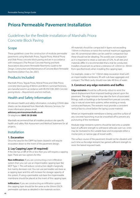
3. Construct any edge restraints and baffles<br />
Edge restraints should be sufficiently robust to resist the<br />
lateral displacement from imposed loadings placed upon the<br />
pavement. The edge restraint may take the form of associated<br />
fittings, walls or buildings or be formed from precast concrete,<br />
clay or natural stone kerb systems, either existing or newly<br />
constructed features. The restraint must provide a consistent<br />
vertical face to a level below the laying course material.<br />
Where an impermeable membrane is being used the surface of<br />
any concrete haunching must be smoothed off to prevent any<br />
puncturing of the membrane<br />
Modular edge restraints systems should be laid onto a suitable<br />
base of sufficient strength to withstand vehicular over-run. Units<br />
may be mortared to the suitable base and incorporate either a<br />
mortar joint, or narrow gap of trowel width.<br />
The surface course of the pavement should not be vibrated until<br />
such time as the edge restraint has gained sufficient strength to<br />
resist the lateral imposed loads.<br />
Where mortar bedding and jointing is adopted, consideration<br />
should be given to the provision of movement joints at regular<br />
intervals.<br />
Where an intermittent restraint may be required, the edge<br />
restraint’s base material may be laid directly onto the opengraded<br />
sub-base material. Should any concern exist about the<br />
restraint bedding material compromising the voidage of the<br />
open-graded sub-base material, a suitable lining material can be<br />
used, separating the two materials.<br />
There are several examples of edge restraint construction within<br />
the standard construction details which can be found at the end<br />
of this section.<br />
Baffles are constructed when there is a significant surface fall<br />
across the CBPP. These should be constructed in concrete and<br />
in non-infiltration systems, a pipe should be placed at the invert<br />
of the sub-base through the concrete to allow the water to flow<br />
towards the outfall. A standard construction detail can be found<br />
at the end of this section (TS-0525).<br />
Due to certain ground conditions, infiltration may not always be<br />
an option therefore an impermeable membrane is required. The<br />
water within the sub-base should be removed via a fin drain or a<br />
network of perforated pipes laid to falls.<br />
The water should then flow through a suitable outflow pipe. The<br />
size of the pipe will be dependent on the site topography and<br />
the volume to be drained. Directly beneath the impermeable<br />
membrane, dependent on the site conditions, a sand blinding<br />
layer may be included to achieve greater flatness and reduce any<br />
potential puncturing of the membrane. Any sharp or protruding<br />
features at formation level that may promote the puncturing<br />
of the membrane should be removed and the remaining area<br />
made good.<br />
4. Construct Outfall (if required)<br />
There are a number outfalls that can be installed into a<br />
permeable pavement; these should be positioned at the low<br />
point of the sub-base construction. Some examples of outfall<br />
constructions can be found in the standard details section.<br />
www.marshalls.co.uk/watermanagement<br />
5. Install Sub-base Material<br />
The sub-base will consist of 20mm OGCR as detailed in the<br />
materials section and will be laid in the same manner as<br />
the capping layer section. Installers should aim to achieve a<br />
tolerance of +/- 20mm from specified levels when installing the<br />
sub-base layer.<br />
6. Install DBM Layer (if required)<br />
The DBM (Dense Base Macadam ) can be installed within<br />
the design where additional structural support or temporary<br />
running surface is required for site traffic over the recently laid<br />
20mm Priora sub-base aggregate.<br />
The material should be a 0/32mm size dense base as given in<br />
BS4987-1:2005 Coated macadam (asphalt concrete) for roads and<br />
other paved areas – Part 1: Specification for constituent materials<br />
and for mixtures, clause 5.2. The binder penetration will be<br />
specified in our design documents.<br />
Installation considerations<br />
It is important to ensure the site tipped DBM is correctly<br />
protected and sheeted from adverse weather, to guarantee<br />
correct material laying temperature is maintained.<br />
On larger areas, generally machine laid by tracked mini (7 tonne)<br />
or midi (14 tonne) paving machine, subject to laying width<br />
or output requirement, material normally supplied to paving<br />
machine hopper by 9 tonne front tip dumpers.<br />
Disturbance to the 20mm aggregate can be kept to a minimum<br />
by ensuring both paving machine and dumper keep to one<br />
laying track. Dumpers must avoid crossing this laying path or<br />
excessive wheel turning, which can cause aggregate rutting.<br />
Any disturbance to the 20mm stone can easily be raked and<br />
re-levelled by labour or rake hands as the surfacing progresses.<br />
Installers should aim to achieve a tolerance of +/- 20mm from<br />
specified levels when installing the DBM layer.<br />
47