Create successful ePaper yourself
Turn your PDF publications into a flip-book with our unique Google optimized e-Paper software.
®<br />
SEWING MACHINE<br />
HZL-25Z<br />
<strong>SERVICE</strong> <strong>MANUAL</strong>
[ 1 ] DISASSEMBLING OF OUTER PARTS<br />
SECTION 1<br />
PAGE 1<br />
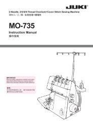
1. Base cover<br />
1. Lower presser foot and lay machine.<br />
2. Remove 3 screws (1) and take out base cover (2).<br />
* Re-assembling should be done in the reverse way.<br />
2. Gear cover<br />
1. Remove screw (1) and take out gear cover (2).<br />
* Re-assembling should be done in the reverse way.
3. Face cover<br />
SECTION 1<br />
PAGE 2<br />
Disassembling<br />
1. Raise presser foot lifter (1).<br />
2. Remove screw (2) and take out face cover (3).<br />
Re-assembling<br />
1. Raise presser foot lifter (1).<br />
2. Insert presser foot lifter (1) into small window (4) of face cover (3).<br />
3. Insert jut (6) of face cover (3) into hole (5) of arm.<br />
4. Fix screw (2) fitting face cover profile to arm profile.
4. SIDE COVER<br />
SECTION 1<br />
PAGE 3<br />
Disassembling<br />
1. Remove screw (1), (9).<br />
2. Push cover (2) as indicated by arrow inserting your finger into the bobbin<br />
winder hole (3) and take out cover (2). 〔Cover (2) has fitting hook (4).〕<br />
3. When it cannot be removed by the above way, take out base cover (5) and<br />
remove cover (2) from lower part.<br />
Re-assembling<br />
1. Insert hook (6) of cover (2) into small window (7) of base cover (5).<br />
2. Set hook (4) of cover (2) into the inside of front cover (8) and fix by screw (1), (9).
5. FRONT COVER<br />
Disassembling<br />
1. Remove side cover and face cover. 〔See page 2 and 3. 〕<br />
2. Remove screws (1), (2), (3) and then securing plate (4).<br />
SECTION 1<br />
PAGE 4<br />
3. Take out face cover (8) removing hook (7) from small window (6) of base<br />
cover (5).<br />
Re-assembling<br />
1. Insert hook (7) of front cover (8) into small window (6) of base cover (5).<br />
2. Fix screws (1), (2) and (3) putting front cover (8) upon arm profile. Also fix<br />
securing plate (4).
6. SHUTTLE COVER<br />
Disassembling<br />
1. Remove screw (1) and take out securing plate (2).<br />
2. Remove shuttle cover (3) extracting as indicated by arrow.<br />
SECTION 1<br />
PAGE 5<br />
* Re-assembling should be done in the reverse way.
7. Hand wheel<br />
SECTION 1<br />
PAGE 6<br />
Re-assembling<br />
1. Set washer (a) and washer (b) in position as illustrated and fix them by<br />
tightening stud screw (c) by hand.<br />
2. Set clutch wheel (d) in position so that its projected portion may be positioned<br />
as illustrated.<br />
3. Fix clutch wheel (d) with screw and tighten it clockwise.<br />
** Disassembling should be done in reverse way.
[ 2 ] ADJUSTMENTS<br />
* Adjustment can be made with or without removal of outer parts.<br />
SECTION 2 - 0<br />
PAGE 1<br />
Adjustment<br />
Without<br />
removing<br />
outer<br />
parts<br />
Front<br />
cover<br />
Removing outer parts<br />
Face<br />
cover<br />
Side<br />
cover<br />
Gear<br />
cover<br />
Base<br />
cover<br />
2 - 1 L-R positioner ○<br />
2 - 2<br />
Needle position<br />
Straight and Zigzag max<br />
2 - 3 Needle side motion ○<br />
○<br />
2 - 4 Clearance cam and cam follower ○<br />
2 - 5 Feed dog height ○<br />
2 - 6 Feed dog longitudinal positioning ○<br />
2 - 7 Feed dog lateral positioning ○<br />
2 - 8<br />
Feed dog timing<br />
Vertical Movement<br />
2 - 8<br />
Feed dog timing<br />
Lateral Movement<br />
2 - 9 "0"-Feeding needle position ○<br />
○<br />
○<br />
2 - 10 Buttonhole sewing -"0" feeding ○<br />
2 - 11 Balance of reverse stitch length ○<br />
2 - 12 Balance of stitch length - stretch stitch ○<br />
2 - 13 Presser foot height ○<br />
2 - 14 Needle height ○<br />
2 - 15 Needle clearance to Shuttle ○ ○<br />
2 - 16 Needle timing to Shuttle ○<br />
2 - 17 Control panel pointer positioning ○<br />
2 - 18 Belt tension ○<br />
2 - 19<br />
Hooking Fork Position of<br />
Needle Threader<br />
2 - 20 Bobbin winder ○<br />
2 - 21 Rubber foot height ○<br />
○
2 - 1 L - R positioner<br />
SECTION 2 - 1<br />
PAGE 1<br />
Checking:<br />
1. Move the needle to the left end by hand.<br />
2. Check if the needle touches the left end of needle hole of needle plate.<br />
NOTE: * Needle will be broken if needle is outside of left end of needle hole.<br />
* Selector dial can not be turned smoothly if there is clearance of<br />
more than 0.3 mm between left end of needle hole and needle.<br />
Adjustment:<br />
1. Lay the machine.<br />
2. Loosen screw (1) and move L - R positioner (2) to left or right for adjustment.<br />
3. Tighten screw (1).
SECTION 2 - 2<br />
PAGE 1<br />
2 - 2 Needle position - Straight stitching and Zigzag stitching,<br />
maximum width<br />
Checking:<br />
1. Remove presser foot.<br />
2. Set machine at "straight stitching A" by turning selector dial.<br />
3. Turning hand wheel by hand, lower the needle and check if needle point<br />
comes to the center of needle plate hole.<br />
4. Set machine at "zigzag stitching C (maximum width)" by turning selector dial.<br />
5. Turning hand wheel by hand, move needle to right and left end, and check if<br />
each clearance between needle and needle hole end of needle plate is equal.<br />
Straight stitching A<br />
Zigzag stitching C<br />
(maximum width)<br />
Adjustment:<br />
1. Remove face cover.<br />
2. Loosen screw (1).<br />
3. Turning eccentric pin (2), adjust needle position.<br />
4. Tighten screw (1) after adjustment.
2 - 3 Needle Position at Zigzag Stitching<br />
SECTION 2 - 3<br />
PAGE 1<br />
Checking:<br />
1. Set machine at "zigzag stitching C, (maximum width)" by turning selector dial.<br />
2. Bring needle to right hand lowest position. Slowly lift up needle and observe<br />
its leftward movement when leaving upper surface of needle plate.<br />
3. Needle should move to left in the range of 0.1 - 0.3 mm when needle point<br />
comes about 1 mm above the needle plate surface.<br />
4. Following ( × ) marked illustrations indicate wrong situation.<br />
Too late<br />
Too early<br />
Adjustment:<br />
1. Remove front cover.<br />
2. Loosen one out of 2 screws (2) on worm gear (1). Another should be set<br />
temporarily.<br />
3. Holding hand wheel, turn worm gear (1), and adjust the angle of worm gear<br />
against gear.<br />
If side motion too early ð Turn worm gear (1) towards you.<br />
If side motion too late ð Turn worm gear (1) away from you.<br />
4. Tighten 2 screws (2) securely after adjustment.<br />
Gear<br />
NOTE: While adjustment, do not move worm gear along shaft. (Otherwise,<br />
engagement with gear and needle side motion is seriously changed.)
2 - 4 Clearance between zigzag cam and cam follower<br />
SECTION 2 - 4<br />
PAGE 1<br />
Checking:<br />
1. Remove presser foot.<br />
2. Set machine at "zigzag stitching C, (maximum width)" by turning selector dial.<br />
3. Lower needle to left side and its lowest position.<br />
4. Turn selector dial towards you (anti-clockwise) and set it between "zigzag<br />
stitching (maximum width)" and "blind stitching".<br />
5. Check if needle point moves about 0.35 mm from above "3" position to left.<br />
Adjustment:<br />
1. Remove side cover.<br />
2. Turn screw (1).<br />
Less than 0.35 mm ð Turn it clockwise.<br />
More than 0.35 mm ð Turn it anti-clockwise.
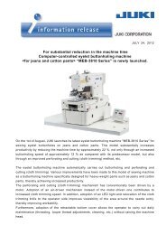
2 - 5 Feed Dog Height<br />
SECTION 2 - 5<br />
PAGE 1<br />
Checking:<br />
1. Set stitch length control at "Maximum", and selector dial at "Straight Stitching A".<br />
2. Remove needle and presser foot.<br />
3. Set feed dog at highest position by turning hand wheel by hand.<br />
4. Check to see if feed dog height (A) is 1.0 mm from needle plate.<br />
Adjustment:<br />
Adjust feed dog height by inserting the minus screw driver into feed lifting arm<br />
(1) and moving it up or down.<br />
Feed dog too low ð Turn the screw driver clockwise.<br />
Feed dog too high ð Turn it anti-clockwise.
2 - 6 Feed dog Longitudinal positioning<br />
SECTION 2 - 6<br />
PAGE 1<br />
Checking:<br />
1. Set stitch length at maximum, and selector dial at "Straight Stitching A".<br />
2. Turning hand wheel, move feed dog to the rear end position, and see if rear<br />
edge of center front dog keeps clearance (A) to the needle plate hole.<br />
3. Move feed dog to the front end, and see if front edge of center dog keeps<br />
clearance (B) to the needle plate hole.<br />
Adjustment:<br />
1. Remove side cover.<br />
2. Move feed dog to its extreme front end position.<br />
3. Loosen screw (2). Moving feed dog forward or backward, adjust the angle<br />
of arm (3) against feed shaft (4).<br />
4. Tighten screw (2) securely after adjustment, keeping the angle of the arm<br />
as adjusted.
2 - 7 Feed Dog Lateral positioning<br />
SECTION 2 - 7<br />
PAGE 1<br />
Checking:<br />
1. Set machine for "maximum stitch length".<br />
2. Check if the groove of needle plate touches left end of feed dog.<br />
3. Check if noise is not made.<br />
4. Check if feed dog keeps alignment against groove of needle plate.<br />
Adjustment:<br />
1. Remove gear cover.<br />
2. Adjustment for above (Checking 2 and 3)<br />
• Loosen screw (2) of setting plate (1), and adjust by moving horizontal<br />
shaft assy (3).<br />
3. Adjustment for above (Checking 4).<br />
• Loosen 2 screws (4). Feed dog (5) must touch groove (6) of needle plate<br />
correctly.
2 - 8 Feed Dog Timing<br />
SECTION 2 - 8<br />
PAGE 1<br />
Vertical Movement<br />
* * Before checking, follow Section 2 - 5 Feed Dog Height.<br />
Checking:<br />
1. Set machine for maximum stitch length.<br />
2. Turning hand wheel, move down feed dog.<br />
3. Check if vertical clearance (P) between needle point and needle plate surface<br />
is within the range of 4 - 6 mm when top of feed dog reaches needle<br />
plate surface level.<br />
Adjustment:<br />
1. Remove base cover.<br />
2. Loosen screw (2) of feed lifting cam (1).<br />
3. Adjust feed dog timing to needle by slightly rotating feed lifting cam (1) in<br />
either direction as shown.<br />
To retard timing ð Turn the cam to A - direction.<br />
To advance timing ð Turn the cam to B - direction.<br />
4. Tighten screw (2) after adjustment.
SECTION 2 -8<br />
PAGE 2<br />
Lateral Movement<br />
Checking:<br />
1. Set machine for maximum stitch length.<br />
2. Set feed dog at the start of its movement (when cam (1) starts to activate<br />
forked connection).<br />
3. Turning hand wheel, bring up needle bar to its highest dead point (A).<br />
4. Check if total lateral movement (B) of feed dog during the period from Step<br />
2 to Step 3 above is within the range of 0.1 - 0.3 mm.<br />
Step 2 Step 3<br />
Adjustment:<br />
1. Remove face cover.<br />
2. Loosen the screw (2) of feed rocking cam (1).<br />
3. Holding feed rocking cam, turn hand wheel and adjust the angle of the cam<br />
to upper shaft.<br />
To retard timing ð Turn hand wheel towards you.<br />
To advance timing ð Turn hand wheel away from you.<br />
4. Tighten set screw (2) securely after adjustment.
2 - 9 "0" - Feeding Needle Positioning<br />
SECTION 2 - 9<br />
PAGE 1<br />
Checking:<br />
1 Set stitch length control at "0", and selector dial at "Straight Stitching A".<br />
2. Place paper under presser foot and take 11 stitches without thread.<br />
3. Deviation of all stitches must be within 0.6 mm in forward direction (about<br />
2/3 of needle thickness).<br />
Adjustment:<br />
1. Inserting the plus screw driver through the hole and adjust the screw inside<br />
of the machine.<br />
Fig. a ) ð Turn anti-clockwise.<br />
Fig. d ) ð Turn clockwise.
2 - 10 Buttonhole sewing - "0" feeding<br />
SECTION 2 - 10<br />
PAGE 1<br />
Checking:<br />
1. Set stitch length control "4".<br />
2. Set machine at "BH No.1, 3" by turning selector dial. (Use buttonhole guide.)<br />
3. Place the paper under buttonhole guide and take 11 zigzag stitches without<br />
thread.<br />
4. Deviation of all stitches must be within 0.6 mm in forward direction (about<br />
2/3 of needle thickness).<br />
Adjustment:<br />
1. Remove side cover.<br />
2. Insert the minus screw driver into the hole (1).<br />
3. Adjust the stitch length within the range of 0 - 0.6 mm by turning driver anticlockwise<br />
or clockwise.
2 - 11 Balance of reverse stitch length<br />
SECTION 2 - 11<br />
PAGE 1<br />
Checking:<br />
Reverse stitch length is within the range of 3.0 - 3.7 mm.<br />
Adjustment:<br />
1. Remove side cover.<br />
2. Loosen screw (3).<br />
3. Holding reverse lever (1), adjust the reverse lever arm (2) upward or<br />
downward and tighten screw (3).<br />
Reverse stitch length is short ð Tighten the screw (3) lifting (2) up.<br />
Reverse stitch length is long ð Tighten the screw (3) lowering (2).<br />
Upward<br />
Downward
SECTION 2 - 12<br />
PAGE 1<br />
2 - 12 Balance of stitch length - Stretch stitching<br />
NOTE: Before checking, follow Section 2 - 9 "0" - feeding needle position.<br />
Checking:<br />
1. Set machine for "zigzag stitching C".<br />
2. Set for "stretch stitching ( )" by turning stitch length control.<br />
3. Sew on a piece of paper and check needle holes on it.<br />
4. Needle must pierce paper 3 times at the same point, on both right and left<br />
end of zigzag stitches.<br />
A<br />
A<br />
Stitch length control ( ) is normal position for stretch stitching.<br />
If you select (L), stitch becomes A .<br />
If you select (S), stitch becomes B .<br />
Adjustment:<br />
1. Remove side cover.<br />
2. Turn lever (1) in either direction to correct the condition.<br />
Turn the lever (1) up ð Reverse stitch length becomes longer.<br />
Turn the lever (1) down ð Forward stitch length becomes longer.<br />
Upward<br />
Downward
2 - 13 Presser Foot Height<br />
SECTION 2 - 13<br />
PAGE 1<br />
Checking:<br />
1. Lower feed dog below the needle plate.<br />
2. Lift up presser foot lever.<br />
3. Check and see if clearance (A) between needle plate and presser foot is<br />
about 5.5 mm.<br />
Adjustment:<br />
1. Remove face cover.<br />
2. Loosen screw (2) of presser bar clamp (1) and adjust the height by vertically<br />
sliding presser bar (3).<br />
3. Tighten screw (2) securely after adjustment, keeping alignment of the foot<br />
against feed dog.
2 - 14 Needle Height<br />
SECTION 2 - 14<br />
PAGE 1<br />
Checking:<br />
1. Remove presser foot.<br />
2. Set selector dial at "Straight Stitch A".<br />
3. Turning hand wheel, bring the needle bar to its highest position.<br />
4. Check and see if the distance between needle point and needle plate surface<br />
is about 14.6 mm.<br />
Adjustment:<br />
1. Remove face plate.<br />
2. Loosen screw (2) of needle bar clamp (1).<br />
3. Vertically sliding needle bar, correct the needle height.<br />
4. Tighten screw (2) securely checking needle hole side after adjustment.<br />
NOTE: After adjustment, follow "2 - 19 Replacement of needle hole threader lever".
2 - 15 Needle Clearance to Shuttle<br />
SECTION 2 - 15<br />
PAGE 1<br />
Checking:<br />
1. Remove bobbin case and shuttle race cover.<br />
2. Set #14 needle.<br />
3. Set machine at "Straight Stitch A" by turning selector dial.<br />
4. Turning hand wheel, bring the shuttle point to the center line of needle.<br />
5. Check if needle clearance to shuttle point (A) is 0 to 0.1 mm.<br />
6. Needle must not touch needle hole.<br />
Adjustment:<br />
1. Remove face cover.<br />
2. Remove screw (1), and loosen screw (2).<br />
3. Move the shaft (3) of supporting assy.<br />
To increase clearance ð Move shaft (3) away from you.<br />
To decrease clearance ð Move shaft (3) towards you.<br />
4. After adjustment, tighten screw (2) keeping shaft (3) from moving.<br />
5. Tighten screw (1).<br />
※ Check if needle does not touch needle hole after adjustment.<br />
If needle touches needle hole, following adjustment is to be made.<br />
Backward<br />
Forward
Adjustment if needle touches needle hole:<br />
SECTION 2 - 15<br />
PAGE 2<br />
1. Bring needle at center of needle hole following the method of "2 - 15<br />
Needle Clearance to Shuttle (Adjustment)".<br />
2. Remove gear cover.<br />
3. Following adjustment is to be made depending on situation.<br />
A - Needle touches front of needle hole (Fig. a ).<br />
1 Loosen screws (4), (5).<br />
2 Adjust needle clearance to shuttle by moving shuttle race assy (6)<br />
away from you (A) and tighten screws (4), (5).<br />
3 Loosen two screws (7). Adjust backlash between lower shaft gear<br />
(8) and shuttle shaft gear (9) and tighten two screws (7).
SECTION 2 - 15<br />
PAGE 3<br />
B - Needle touches back of needle hole (Fig. b - PAGE 2).<br />
1 Loosen screws (11), (12) of setting plate (10) for lower shaft bush.<br />
However, lower shaft bush (13) must not float. (Big clearance should<br />
not be made between setting plate and bush.)<br />
2 Moving lower shaft gear assy (14) to left (C). Lower shaft gear (8)<br />
must always engage with shuttle shaft gear.<br />
3 Loosen screws (4), (5).<br />
4 Adjust needle clearance to shuttle by moving shuttle race assy to<br />
wards you (B direction - PAGE 2) and tighten screws (4), (5).<br />
5 Move lower shaft gear assy (14) along shaft and adjust backlash be<br />
tween lower shaft gear (8) and shuttle shaft gear (9).<br />
6 Tighten screws (11), (12).<br />
※ Check following "Checking rotating direction of shuttle race assy" (next<br />
page) and "2 - 15 Needle timing to shuttle" after adjustment.
Checking rotating direction of shuttle race assy:<br />
Align needle with the right edge (B) of cut portion (A).<br />
SECTION 2 - 15<br />
PAGE 4<br />
Checking backlash of shuttle shaft gear and lower shaft gear:<br />
1. Remove bobbin case, shuttle cover, and shuttle hook.<br />
2. Turning hand wheel, rotate shuttle driver (1) and locate the point of minimum<br />
backlash.<br />
3. Check if the backlash is approximately zero at this point.
2 - 16 Needle Clearance to Shuttle<br />
SECTION 2 - 16<br />
PAGE 1<br />
* * Before checking, follow Section 2 - 2 Needle Position at Straight and Maximum<br />
Zigzag Width and 2 - 14 Needle Height.<br />
Checking:<br />
1. Remove bobbin case and shuttle race cover.<br />
2. Set machine at "zigzag stitching C, (maximum width)" by turning selector dial.<br />
3. Turning hand wheel, bring up needle from its right hand lowest point until<br />
shuttle hook point comes to align with left side of needle. Check if clearance<br />
(A) between hook point and upper edge of needle eye is about 1.0 mm.<br />
Adjustment:<br />
1. Loosen bolt (2) of lower shaft arm (1).<br />
2. Rotate shuttle with finger until hook point comes to align with the left side of<br />
needle.<br />
3. Holding shuttle at this position, slowly bring up needle until the correct vertical<br />
clearance is attained between shuttle hook point and upper edge of<br />
needle eye.<br />
4. Tighten screw (2) securely after adjustment, keeping the angle of the shuttle<br />
as adjusted.<br />
5. Recheck needle/ shuttle timing after adjustment.
2 - 17 Control panel pointer positioning<br />
SECTION 2 - 17<br />
PAGE 1<br />
Checking:<br />
1. Set machine for "BH left 2" (pointer at highest position).<br />
2. Check if pointer is set in correct position of window of control panel.<br />
Adjustment:<br />
1. Remove side cover.<br />
2. Loosen two screws (1) of selector dial and set pointer turning dial.<br />
3. Tighten two screws (1).<br />
Control panel<br />
Selector dial<br />
Gear<br />
※ Above adjustment can not be made if belt tension is too loose.<br />
Then loosen screw (2) and adjust belt tension turning eccentric roller (3).
2 - 18 Belt tension<br />
SECTION 2 - 18<br />
PAGE 1<br />
* Belt tension should be adjusted in case of belt jumping on heavy material sewing<br />
or slow rotation.<br />
Reference:<br />
Belt is bent about 7 mm when pushing middle portion of belt between upper<br />
shaft and motor with pressure of 200 g.<br />
Pressure<br />
Adjustment:<br />
1. Remove side cover.<br />
2. Loosen two screws (1). Adjust belt tension by moving motor and tighten<br />
screws (1).
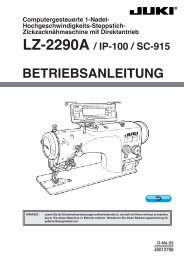
2 - 19 Hooking Fork Position of Needle Threader<br />
Checking:<br />
1. Check and see if #14 needle is used and it is not bent.<br />
2. Set machine for Straight Stitch at center needle<br />
position.<br />
3. Raise the needle to its highest position by rotating<br />
the hand wheel towards you.<br />
4. Lowering needle hole threader lever, check and<br />
see if hook (1) inserts into needle hole.<br />
( 3 )<br />
SECTION 2 - 19<br />
PAGE 1<br />
( 1 )<br />
Adjustment when hook (1) is deviated horizontally or bent vertically:<br />
Correct the condition using small screw driver as illustrated.<br />
<br />
<br />
Deviated horizontally<br />
Bent vertically<br />
Adjustment when hook (1) is deviated vertically:<br />
1. Remove face cover.<br />
2. Turning hand wheel by hand, bring needle bar to its highest<br />
position.<br />
3. Lower needle hole threader lever (3).<br />
4. Pushing needle hole threader lever (3) away from you,<br />
insert hook (1) into needle hole, and keep it.<br />
5. Loosen stopper screw (4).<br />
6. Holding threader stopper (4) onto stopper pin (8), tighten stopper screw (5).<br />
Make sure to align the screw (5) with the screw (7) on needle bar clamp (6)<br />
Center<br />
( 8 )<br />
( 4 )<br />
( 5 )<br />
( 6 )<br />
( 7 )
SECTION 2 - 19<br />
PAGE 2<br />
Exchange of needle hole threader lever:<br />
1. Remove presser foot.<br />
2. Raise needle to its highest position.<br />
3. Push needle hole threader lever down by pliers or forked driver as illustrated.<br />
4. Remove needle hole threader lever (3).<br />
Knock pin<br />
( 3 )
2 - 20 Bobbin Winder<br />
SECTION 2 - 20<br />
PAGE 1<br />
A. Winding balance<br />
Checking:<br />
1. Wind thread on the bobbin.<br />
2. Check if the thread is wound evenly.<br />
Adjustment:<br />
1. Insert box driver (hexagonal box driver, etc.) into the bobbin winder shaft<br />
and bent it.<br />
Lower part is wound too much (c) ð Bent to left side.<br />
Upper part is wound too much (a) ð Bent to right side.<br />
Left<br />
Right<br />
B. Winding volume<br />
Adjustment:<br />
1. Loosen screw (1) and adjust the bobbin winder stopper (2) ( ).<br />
(The best volume of winding is 80% at maximum.)
2 - 21 Rubber foot height<br />
SECTION 2 - 21<br />
PAGE 1<br />
Checking:<br />
1. Put the machine on the flat table.<br />
2. Check the balance of the machine.<br />
Adjustment:<br />
1. Loosen nut (1).<br />
2. Insert the driver into the hole (2) and adjust by turning it.<br />
3. Tighten nut (1) securely after adjustment.<br />
* Use screw driver P#.74793 included in the accessories.
®<br />
8-2-1, KOKURYO-CHO,<br />
CHOFU-SHI, TOKYO 182-8655, JAPAN<br />
PHONE: 03(3480)5034<br />
FAX: 03(3480)5037<br />
http: //www.juki.co.jp<br />
E-mail: hsm@juki.co.jp<br />
Copyright © 2007 <strong>JUKI</strong> CORPORATlON<br />
All right reserved throughout the world.<br />
40058010 2007/01