AZB 806 - Junkers
AZB 806 - Junkers
AZB 806 - Junkers

Create successful ePaper yourself
Turn your PDF publications into a flip-book with our unique Google optimized e-Paper software.
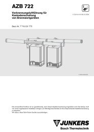
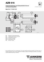
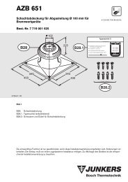
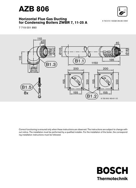
<strong>AZB</strong> <strong>806</strong><br />
Horizontal Flue Gas Ducting<br />
for Condensing Boilers ZWBR 7, 11-25 A<br />
7 719 001 890<br />
6 720 610 163GB (99.08) OSW<br />
110<br />
40<br />
40<br />
Ø82<br />
Ø127<br />
110<br />
Ø125<br />
Ø 80<br />
Ø80<br />
Ø125<br />
B1.3<br />
B1.1<br />
200<br />
1150<br />
200<br />
135<br />
B1.5<br />
8x<br />
155<br />
Ø 126<br />
155<br />
200<br />
155<br />
B1.2<br />
Ø 126<br />
155<br />
200<br />
6 720 610 163-01.1O<br />
Correct functioning is ensured only when these instructions are observed. The instructions are subject to change without<br />
notice. The installation must be performed by a qualified installer. For the installation of the boiler, the corresponding<br />
installation instructions must be followed.
<strong>AZB</strong> <strong>806</strong><br />
Contents<br />
Page<br />
1 Use 3<br />
2 General 3<br />
3 Assembly Instructions 3<br />
4 Assembly of the <strong>AZB</strong> <strong>806</strong> with flue gas<br />
discharge through the outside wall 4<br />
5 Minimum Installation Dimensions (C 13 )<br />
for ZWBR 7, 11-25 A 6<br />
6 Flue gas duct sideways through the<br />
outside wall (C 13 ), without forward<br />
directional elbow pieces, for<br />
ZWBR 7/11-25 A 7<br />
7 Flue gas duct sideways through the<br />
outside wall (C 13 ), with forward<br />
directional elbow pieces, for<br />
ZWBR 7/11-25 A 8<br />
8 Flue gas duct through the outside wall<br />
(C 13 ) to the rear, with or without<br />
sideways directional elbow piece, for<br />
ZWBR 7/11-25 A 9<br />
9 Flue gas duct through the outside wall<br />
(C 13 ) for ZWBR 7/11-25 A 10<br />
10 Horizontal flue gas duct through<br />
the roof with dormer (C 13 ) for<br />
ZWBR 7/11-25 A 11<br />
2 0 163GB
<strong>AZB</strong> <strong>806</strong><br />
1 Use<br />
Appliance type <strong>AZB</strong> <strong>806</strong><br />
ZWBR 7, 11-25 A<br />
X<br />
2 General<br />
The installation of a gas condensing boiler must be in<br />
accordance with the relevant British Standard, the relevant<br />
Building Regulations and any local rules.<br />
The ZWBR 7, 11-25 A gas condensing boilers conform<br />
to the requirements of the Gas Appliance Directive<br />
(90/396/EWG) and prEN677.<br />
The flue gas accessory is part of CE approval when discharging<br />
flue gas according to C 13 . For this reason,<br />
only original Bosch flue gas accessories may be used.<br />
The surface temperature of the fresh air duct is below<br />
85 °C. Therefore no minimum distances to combustible<br />
building materials are necessary. The regulations can<br />
deviate, however, and might prescribe minimum distances<br />
to combustible materials.<br />
3 Assembly Instructions<br />
The flue gas accessories must be installed for discharge<br />
to the outside at a gradient of 3 %. If the appliance<br />
is installed in a cold location i. e. roof space, the<br />
fresh air duct must be insulated.<br />
Flue gas opening through the outside wall<br />
Installations where the double-connection duct<br />
enters a shaft below ground level can lead to<br />
unintentional switching off in winter due to ice<br />
forming in the double pipe and are to be avoided<br />
as far as possible!<br />
LPG appliances must not be installed below<br />
ground level.<br />
The maximum flue gas / fresh air duct length is<br />
8000 mm. A maximum of three 90° elbows is permissible.<br />
Instead of one 90° elbow, two 45° bends can also<br />
be used.<br />
0 163GB 3
<strong>AZB</strong> <strong>806</strong><br />
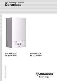
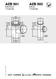
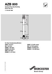
4 Assembly of the <strong>AZB</strong> <strong>806</strong> with flue<br />
gas discharge through the outside<br />
wall<br />
Note:<br />
Before connecting the flue gas accessories,<br />
lubricate the seals on the sleeves lightly with<br />
solvent-free grease (e. g. Vaseline).<br />
– Slide the 90° double pipe elbow (B1.3), lightly twisting,<br />
onto the connecting piece on the appliance (figure<br />
4 ) ) until it can go no further.<br />
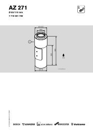
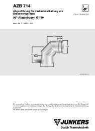
– Determine the length L of the terminal assembly<br />
(B1.1). Make sure that the distance from the outside<br />
wall to the end of the terminal assembly (B1.1) is<br />
accounted for (figure 2 ).<br />
– Make the opening in the wall. In so doing, account for<br />
the 3 % gradient of the flue gas duct (for Ø D, see<br />
figure 3 and Table 1).<br />
– Place the inner cover plate (B1.2) onto the terminal<br />
assembly (B1.1) (figure 4 ).<br />
– Insert the terminal assembly (B1.1) from inside to the<br />
outside through the wall opening (if necessary<br />
remove the double pipe elbow), and then push it,<br />
lightly twisting, into the socket of the 90° double pipe<br />
elbow (B1.3). Make sure that the fresh air venting slit<br />
in the terminal assembly (B1.1) is directed downwards<br />
(figure 4 ).<br />
– Place the outside cover plate (B1.2) over the terminal<br />
assembly (B1.1) (figure 4 ).<br />
– Drill the fixation holes for both the cover plates and<br />
fasten these using rawlplugs and screws (B1.5) (figure<br />
4 ).<br />
– Press the protective grating gently together and<br />
place it into the end socket of the terminal assembly<br />
(B1.1) (figure 4 ).<br />
Wall thickness<br />
S in cm<br />
17,5-22 150<br />
24-28 160<br />
36-40 170<br />
50 180<br />
Table 1<br />
Wall opening<br />
Ø D in mm<br />
Key to figure 2 and 4 :<br />
B1.1 Terminal assembly<br />
B1.2 Cover plates<br />
B1.3 Double pipe elbow<br />
4 0 163GB
2<br />
<strong>AZB</strong> <strong>806</strong><br />
160<br />
200<br />
10<br />
3<br />
min<br />
150<br />
S<br />
ø125<br />
øD<br />
3%<br />
ØD<br />
4498-3.1S<br />
B1.1<br />
B1.2<br />
6 720 604 911-03.1O<br />
4<br />
B1.2<br />
B1.3<br />
3%<br />
B1.2<br />
B1.1<br />
B1.5<br />
6 720 610 163-04.1O<br />
0 163GB 5
<strong>AZB</strong> <strong>806</strong><br />
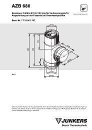
5 Minimum Installation Dimensions<br />
(C 13 ) for ZWBR 7, 11-25 A<br />
(figures 5 and 6 )<br />
– Ø D see figure and Table 1<br />
3 ØD<br />
5<br />
3%<br />
10<br />
850<br />
1025<br />
min 1110<br />
Ø125<br />
512<br />
DN 20<br />
6 720 610 163-05.1O<br />
6<br />
Ø125<br />
Ø82<br />
115<br />
min 1110<br />
850<br />
390<br />
406,5<br />
min 600<br />
6 720 610 163-06.1O<br />
6 0 163GB
<strong>AZB</strong> <strong>806</strong><br />
6 Flue gas duct sideways through the outside wall (C 13 ), without forward directional<br />
elbow pieces, for ZWBR 7/11-25 A<br />
Caution: The maximum length must not exceed<br />
L max = 8000 mm (figure 8 )!<br />
7<br />
B1.1 B1.3<br />
Ø125<br />
B1.2 160 210<br />
min 100<br />
512<br />
115<br />
min 100<br />
390<br />
7 :<br />
B1: <strong>AZB</strong> <strong>806</strong><br />
L max = 1020 mm<br />
L<br />
6 720 610 163-07.1O<br />
8<br />
B1.1<br />
210<br />
B2<br />
B1.3<br />
min 100<br />
Ø125<br />
115<br />
390<br />
B1.2<br />
LF<br />
160<br />
512<br />
L<br />
6 720 610 163-08.1O<br />
8 :<br />
B1: <strong>AZB</strong> <strong>806</strong><br />
B2: <strong>AZB</strong> 808, LF = 990 mm<br />
L max = 8000 mm<br />
0 163GB 7
<strong>AZB</strong> <strong>806</strong><br />
7 Flue gas duct sideways through the outside wall (C 13 ), with forward directional<br />
elbow pieces, for ZWBR 7/11-25 A<br />
Caution: The maximum length must not exceed<br />
L max = 8000 mm (figure 10)!<br />
9<br />
B6.2 B6.1 B1.3 min 100<br />
B1.1<br />
210<br />
195<br />
230<br />
115<br />
Ø125<br />
390<br />
B1.2<br />
max 950<br />
512<br />
160<br />
L<br />
6 720 610 163 09.1O<br />
9 :<br />
B1: <strong>AZB</strong> <strong>806</strong><br />
B6: <strong>AZB</strong> 814<br />
L max = 1210 mm<br />
10<br />
B2<br />
B1.3<br />
min 100<br />
B1.1<br />
210<br />
195<br />
230<br />
115<br />
Ø125<br />
LF<br />
390<br />
B1.2<br />
160<br />
max 950<br />
B6.2<br />
B6.1<br />
512<br />
L<br />
6 720 610 163-10.1O<br />
10:<br />
B1: <strong>AZB</strong> <strong>806</strong><br />
B2: <strong>AZB</strong> 808, LF = 990 mm<br />
B6: <strong>AZB</strong> 814<br />
L max = 8000 mm<br />
8 0 163GB
<strong>AZB</strong> <strong>806</strong><br />
8 Flue gas duct through the outside wall (C 13 ) to the rear, with or without sideways<br />
directional elbow piece, for ZWBR 7/11-25 A<br />
Caution: The maximum length must not exceed<br />
L max = 8000 mm (figure 12)!<br />
11<br />
B1.2<br />
Ø125<br />
160<br />
115<br />
115<br />
210<br />
B1.1<br />
L<br />
min 100<br />
B1.3<br />
390<br />
512<br />
6 720 610 163-11.1O<br />
11:<br />
B1: <strong>AZB</strong> <strong>806</strong><br />
L max = 1020 mm<br />
12<br />
B1.2<br />
Ø125<br />
160<br />
210<br />
B1.1<br />
L2<br />
min 100<br />
110<br />
LF<br />
115<br />
B3<br />
B2<br />
512<br />
B1.3<br />
390<br />
L1<br />
6 720 610 163-12.1O<br />
12:<br />
B1: <strong>AZB</strong> <strong>806</strong><br />
B2: <strong>AZB</strong> 808, LF = 990 mm<br />
B3: <strong>AZB</strong> 807<br />
L = L 1 + L 2<br />
L max = 8000 mm<br />
0 163GB 9
<strong>AZB</strong> <strong>806</strong><br />
9 Flue gas duct through the outside wall (C 13 ) for ZWBR 7/11-25 A<br />
Caution: The maximum length must not exceed<br />
L max = 8000 mm!<br />
13<br />
L1<br />
B1.1 min 100<br />
B3<br />
LF<br />
115<br />
LF<br />
390<br />
B2<br />
512<br />
B1.1<br />
210<br />
B2<br />
L2<br />
Ø125<br />
B1.2<br />
160<br />
L3<br />
B3<br />
6 720 610 163-13.1O<br />
13:<br />
B1: <strong>AZB</strong> <strong>806</strong><br />
B2: <strong>AZB</strong> 808, LF = 990 mm<br />
B3: <strong>AZB</strong> 807<br />
L max = L 1 + L 2 + L 3 = 8000 mm<br />
L 3 max = 1020 mm<br />
10 0 163GB
<strong>AZB</strong> <strong>806</strong><br />
10 Horizontal flue gas duct through the roof with dormer (C 13 ) for ZWBR 7/11-25 A<br />
Caution: The maximum length must not exceed<br />
L max = 8000 mm!<br />
14<br />
B1.3<br />
L<br />
3%<br />
210<br />
19<br />
240<br />
400<br />
B1.1<br />
Ø125<br />
160<br />
min 1112<br />
960<br />
850<br />
>30°<br />
512<br />
14:<br />
B1: <strong>AZB</strong> <strong>806</strong><br />
19: Dormer (provided by the client)<br />
15<br />
L max = 1020 mm<br />
L<br />
6 720 610 163-14.1O<br />
210<br />
B1.3<br />
LF<br />
19<br />
240<br />
400<br />
3%<br />
B2<br />
˘125<br />
B1.1<br />
B1<br />
˘125<br />
960<br />
160<br />
850<br />
>30°<br />
6 720 610 163-15.1O<br />
512<br />
15:<br />
B1: <strong>AZB</strong> <strong>806</strong><br />
B2: <strong>AZB</strong> 808, LF = 990 mm<br />
19: Dormer (provided by the client)<br />
L max = 8000 mm<br />
0 163GB 11
Worcester Heat Systems Limited<br />
Cotswold Way, Warndon,<br />
Worcester WR4 9SW.<br />
Telephone: (0 19 05) 75 46 24.<br />
Fax: (0 19 05) 75 46 19.<br />
Technical:<br />
Telephone: (09 90) 26 62 41<br />
Fax: (0 19 05) 75 72 24<br />
Service:<br />
Telephone: 03 45 25 62 06<br />
Fax: (0 19 05) 75 47 01