ASSEMBLY/DISASSEMBLY - Dodge-pt.com
ASSEMBLY/DISASSEMBLY - Dodge-pt.com
ASSEMBLY/DISASSEMBLY - Dodge-pt.com

You also want an ePaper? Increase the reach of your titles
YUMPU automatically turns print PDFs into web optimized ePapers that Google loves.
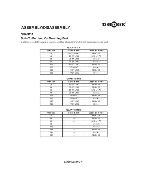
<strong>ASSEMBLY</strong>/DIS<strong>ASSEMBLY</strong><br />
QUANTIS<br />
Bolts To Be Used On Mounting Feet<br />
In addition to the bolts below, it is re<strong>com</strong>mended that a lockwasher or other anti-loosening device be used.<br />
QUANTIS ILH<br />
Unit Size Grade 5 Inch Grade 8.8 Metric<br />
38 5/16-18 UNC M8 x 1.25<br />
48 1/2-13 UNC M12 x 1.75<br />
68 5/8-11 UNC M16 x 2<br />
88 5/8-11 UNC M16 x 2<br />
108 3/4-10 UNC M20 x 2.5<br />
128 7/8-9 UNC M24 x 3<br />
148 1-1/4-7 UNC M30 x 3.5<br />
168 1-1/2-6 UNC M36 x 4<br />
QUANTIS RHB<br />
Unit Size Grade 5 Inch Grade 8.8 Metric<br />
38 3/8-16 UNC M10 x 1.5<br />
48 3/8-16 UNC M10 x 1.5<br />
68 1/2-13 UNC M12 x 1.75<br />
88 5/8-11 UNC M16 x 2<br />
108 7/8-9 UNC M20 x 2.5<br />
128 7/8-9 UNC M24 x 3<br />
148 1-1/4-7 UNC M30 x 3.5<br />
168 1-1/2-6 UNC M36 x 4<br />
Unit Size<br />
QUANTIS MSM<br />
Grade 5 Inch Grade 8.8 Metric<br />
38 --- M8 x 1.25<br />
48 --- M10 x 1.5<br />
68 --- M12 x 1.75<br />
88 --- M16 x 2<br />
108 --- M16 x 2<br />
128 --- M20 x 2.5<br />
148 --- M24 x 3<br />
168 --- M30 x 3.5<br />
ENGINEERING-1
<strong>ASSEMBLY</strong>/DIS<strong>ASSEMBLY</strong><br />
QUANTIS<br />
Bolts And Tightening Torque For B5 Output Flanges<br />
(Output Flange to Gearcase)<br />
Product Type Unit Size<br />
Bolt - 8.8<br />
Property Class<br />
ENGINEERING-2<br />
Tightening<br />
Torque (Nm)<br />
Tightening<br />
Torque (ft-lb)<br />
ILH 38 M8 25 18<br />
ILH 48 M10 50 37<br />
ILH 68 M12 90 66<br />
ILH 88 M16 210 155<br />
ILH 108 M16 210 155<br />
ILH 128 M16 210 155<br />
ILH 148 M16 210 155<br />
ILH 168 M16 210 155<br />
MSM/RHB 38 M8 25 18<br />
MSM/RHB 48 M10 50 37<br />
MSM/RHB 68 M12 90 66<br />
MSM/RHB 88 M12 90 66<br />
MSM/RHB 108 M16 210 155<br />
MSM/RHB 128 M16 210 155<br />
MSM/RHB 148 M20 500 369<br />
MSM/RHB 168 M20 500 369
<strong>ASSEMBLY</strong>/DIS<strong>ASSEMBLY</strong><br />
QUANTIS<br />
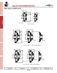
NEMA C-Face Input Flange Details<br />
NEMA Clamp Collar<br />
Motor Frame<br />
56C 4.500<br />
140TC 4.500<br />
180TC 8.500<br />
210TC 8.500<br />
250TC 8.500<br />
280TC 10.500<br />
320TC 12.500<br />
360TC 12.500<br />
φAK1<br />
tol<br />
+0.0009<br />
-0.0000<br />
+0.0009<br />
-0.0000<br />
+0.0011<br />
-0.0000<br />
+0.0011<br />
-0.0000<br />
+0.0011<br />
-0.0000<br />
+0.0013<br />
-0.0000<br />
+0.0014<br />
-0.0000<br />
+0.0014<br />
-0.0000<br />
NEMA Three-Piece Coupled<br />
Motor Frame φAK1<br />
tol<br />
56C 4.500<br />
+0.0009<br />
-0.0000<br />
140TC 4.500<br />
+0.0009<br />
-0.0000<br />
180TC 8.500<br />
+0.0011<br />
-0.0000<br />
210TC 8.500<br />
+0.0011<br />
-0.0000<br />
250TC 8.500<br />
+0.0011<br />
-0.0000<br />
280TC 10.500<br />
+0.0013<br />
-0.0000<br />
320TC 12.500<br />
+0.0013<br />
-0.0000<br />
360TC 12.500<br />
+0.0014<br />
-0.0000<br />
φAJ1<br />
φBD1<br />
ENGINEERING-3<br />
φBF1<br />
5.870 6.61 0.43 0.625<br />
5.870 6.61 0.43 0.875<br />
7.250 8.98 0.53 1.125<br />
7.250 9.02 0.53 1.375<br />
7.250 10.23 0.53 1.625<br />
9.000 11.89 0.53 1.875<br />
11.000 14.01 0.67 2.125<br />
11.000 14.01 0.67 2.375<br />
φAJ1<br />
φBD1<br />
φBF1<br />
5.870 6.61 0.43 0.625<br />
5.870 6.61 0.43 0.875<br />
7.250 8.98 0.53 1.125<br />
7.250 8.98 0.53 1.375<br />
7.250 10.00 0.53 1.625<br />
9.020 11.26 0.53 1.875<br />
10.980 13.98 0.67 2.125<br />
10.980 13.98 0.67 2.375<br />
φFU<br />
tol FY FZ<br />
+0.0007<br />
-0.0000<br />
0.709 0.188<br />
+0.0008<br />
-0.0000<br />
0.964 0.188<br />
+0.0008<br />
-0.0000<br />
1.241 0.250<br />
+0.0010<br />
-0.0000<br />
1.518 0.310<br />
+0.0010<br />
-0.0000<br />
1.796 0.375<br />
+0.0010<br />
-0.0000<br />
2.096 0.500<br />
+0.0016<br />
-0.0004<br />
2.350 0.500<br />
+0.0016<br />
-0.0004<br />
2.651 0.625<br />
φFU<br />
tol FY FZ<br />
+0.0007<br />
-0.0000<br />
0.709 0.188<br />
+0.0008<br />
-0.0000<br />
0.964 0.188<br />
+0.0008<br />
-0.0000<br />
1.241 0.250<br />
+0.0010<br />
-0.0000<br />
1.518 0.310<br />
+0.0010<br />
-0.0000<br />
1.796 0.375<br />
+0.0010<br />
-0.0000<br />
2.096 0.500<br />
+0.0012<br />
-0.0000<br />
2.350 0.500<br />
+0.0012<br />
-0.0000<br />
2.651 0.625
<strong>ASSEMBLY</strong>/DIS<strong>ASSEMBLY</strong><br />
QUANTIS<br />
IEC C-Face Input Flange Details<br />
IEC Clamp Collar<br />
Motor Frame φAK1<br />
tol<br />
71D 4.33<br />
+0.0014<br />
+0.0000<br />
80D 5.12<br />
+0.0016<br />
+0.0000<br />
90D 5.12<br />
+0.0016<br />
+0.0000<br />
100D 7.09<br />
+0.0016<br />
+0.0000<br />
112D 7.09<br />
+0.0016<br />
+0.0000<br />
132D 9.06<br />
+0.0018<br />
+0.0000<br />
160D 9.84<br />
+0.0018<br />
+0.0000<br />
180D 9.84<br />
+0.0018<br />
+0.0000<br />
200D 11.81<br />
+0.0020<br />
+0.0000<br />
IEC Three-Piece Coupled<br />
Motor Frame φAK1<br />
tol<br />
80D 5.12<br />
+0.0016<br />
+0.0000<br />
90D 5.12<br />
+0.0016<br />
+0.0000<br />
100D 7.09<br />
+0.0016<br />
+0.0000<br />
112D 7.09<br />
+0.0016<br />
+0.0000<br />
132D 9.06<br />
+0.0018<br />
+0.0000<br />
160D 9.84<br />
+0.0018<br />
+0.0000<br />
180D 9.84<br />
+0.0028<br />
+0.0000<br />
200D 11.81<br />
+0.0032<br />
+0.0000<br />
225D 13.78<br />
+0.0035<br />
+0.0000<br />
250D 17.72<br />
+0.0038<br />
+0.0000<br />
φAJ1<br />
φBD1<br />
φBF1<br />
φFU<br />
tol FY FZ<br />
5.12 6.30 M8 x 17 0.55<br />
+0.0013<br />
+0.0006<br />
0.63 0.20<br />
6.50 7.87 M10 0.75<br />
+0.0016<br />
+0.0008<br />
0.85 0.24<br />
6.50 7.87 M10 0.94<br />
+0.0016<br />
+0.0008<br />
1.06 0.31<br />
8.46 9.84 M12 1.10<br />
+0.0016<br />
+0.0008<br />
1.22 0.31<br />
8.46 9.84 M12 1.10<br />
+0.0016<br />
+0.0008<br />
1.22 0.31<br />
10.43 11.81 M12 1.50<br />
+0.0020<br />
+0.0010<br />
1.61 0.40<br />
11.81 13.78 M16 1.65<br />
+0.0020<br />
+0.0010<br />
1.77 0.47<br />
11.81 13.78 M16 x 22 1.89<br />
+0.0020<br />
+0.0010<br />
2.03 0.55<br />
13.78 15.75 M16 2.17<br />
+0.0024<br />
+0.0012<br />
2.32 0.63<br />
φAJ1<br />
φBD1<br />
φBF1<br />
φFU<br />
tol FY FZ<br />
6.50 7.87 M10 0.75<br />
+0.0008<br />
+0.0000<br />
0.86 0.24<br />
6.50 7.87 M10 0.94<br />
+0.0008<br />
+0.0000<br />
1.07 0.31<br />
8.46 9.84 M12 1.10<br />
+0.0008<br />
+0.0000<br />
1.23 0.31<br />
8.46 9.84 M12 1.10<br />
+0.0008<br />
+0.0000<br />
1.23 0.31<br />
10.43 11.81 M12 1.50<br />
+0.0010<br />
+0.0000<br />
1.63 0.39<br />
11.81 13.78 M16 1.65<br />
+0.0010<br />
+0.0000<br />
1.78 0.47<br />
11.81 13.78 M16 1.89<br />
+0.0010<br />
+0.0000<br />
2.03 0.55<br />
13.78 15.75 M16 2.17<br />
+0.0012<br />
+0.0000<br />
2.32 0.63<br />
15.75 17.72 M16 2.36<br />
+0.0012<br />
+0.0000<br />
2.52 0.71<br />
19.69 21.65 M16 2.56<br />
+0.0012<br />
+0.0000<br />
2.72 0.71<br />
ENGINEERING-4
<strong>ASSEMBLY</strong>/DIS<strong>ASSEMBLY</strong><br />
QUANTIS<br />
Separate Flange / Shaft Details<br />
ØFU<br />
FZ<br />
45°<br />
ØAK1<br />
ØAJ1<br />
ØBD1<br />
SEPARATE GROUPS<br />
71-112<br />
ØBF1<br />
4 HOLES<br />
Separate Input<br />
φBD1<br />
φAK1<br />
tol<br />
71<br />
5.35<br />
136<br />
3.740<br />
95<br />
+0.0005<br />
-0.0004<br />
+0.013<br />
-0.009<br />
80<br />
5.51<br />
140<br />
3.740<br />
95<br />
+0.0005<br />
-0.0004<br />
+0.013<br />
-0.009<br />
90<br />
5.51<br />
140<br />
3.740<br />
95<br />
+0.0005<br />
-0.0004<br />
+0.013<br />
-0.009<br />
100<br />
6.85<br />
174<br />
4.724<br />
120<br />
+0.0005<br />
-0.0004<br />
+0.013<br />
-0.009<br />
112<br />
7.01<br />
178<br />
4.724<br />
120<br />
+0.0005<br />
-0.0004<br />
+0.013<br />
-0.009<br />
132<br />
8.43<br />
214<br />
6.299<br />
160<br />
+0.0006<br />
-0.0004<br />
+0.014<br />
-0.011<br />
160<br />
9.88<br />
251<br />
6.299<br />
160<br />
+0.0006<br />
-0.0004<br />
+0.014<br />
-0.011<br />
180<br />
11.65<br />
296<br />
7.677<br />
195<br />
+0.0006<br />
-0.0005<br />
+0.016<br />
-0.013<br />
225<br />
13.46<br />
342<br />
9.843<br />
250<br />
+0.0006<br />
-0.0005<br />
+0.016<br />
-0.013<br />
250<br />
15.59<br />
396<br />
9.843<br />
250<br />
+0.0006<br />
-0.0005<br />
+0.016<br />
-0.013<br />
(G) See Footnote on inside back cover.<br />
FZ<br />
ØFU<br />
ØAK1<br />
ØAJ1<br />
ØBD1<br />
φAJ<br />
1 φBF1<br />
x De<strong>pt</strong>h (G)<br />
φFU<br />
tol<br />
Inch/mm<br />
FZ<br />
4.57 M8 x 0.55 0.625<br />
+0.0000<br />
-0.0005<br />
0.71<br />
116 M8 x 14 16<br />
+0.012<br />
+0.001<br />
18<br />
4.57 M8 x 0.55 0.750<br />
+0.0000<br />
-0.0005<br />
0.84<br />
116 M8 x 14 19<br />
+0.015<br />
+0.002<br />
21.5<br />
4.57 M8 x 0.55 0.875<br />
+0.0000<br />
-0.0005<br />
0.96<br />
116 M8 x 14 24<br />
+0.015<br />
+0.002<br />
27<br />
5.71 M10 x 0.67 1.125<br />
+0.0000<br />
-0.0005<br />
1.24<br />
145 M10 x 17 28<br />
+0.015<br />
+0.002<br />
31<br />
5.71 M10 x 0.67 1.250<br />
+0.0000<br />
-0.0005<br />
1.37<br />
145 M10 x 17 28<br />
+0.015<br />
+0.002<br />
31<br />
7.24 M10 x 0.67 1.375<br />
+0.0000<br />
-0.0005<br />
1.52<br />
184 M16 x 22 38<br />
+0.018<br />
+0.002<br />
41<br />
7.24 Ml 6 x 0.87 1.625<br />
+0.0000<br />
-0.0010<br />
1.80<br />
184 M16 x 28 42<br />
+0.018<br />
+0.002<br />
45<br />
9.06 M16 x 1.10 2.125<br />
+0.0000<br />
-0.0010<br />
2.35<br />
230 M16 x 28 55<br />
+0.021<br />
+0.002<br />
59<br />
11.81 M16 x 0.87 2.125<br />
+0.0000<br />
-0.0010<br />
2.35<br />
300 M16 x 22 60<br />
+0.030<br />
+0.011<br />
64<br />
11.81 M16 x 0.87 2.375<br />
+0.0000<br />
-0.0010<br />
2.65<br />
300 M16 x 22 65<br />
+0.030<br />
+0.011<br />
69<br />
ENGINEERING-5<br />
ØBF1<br />
4 HOLES<br />
SEPARATE GROUPS<br />
1320180<br />
ØFU<br />
FZ<br />
ØBF1<br />
8 HOLES<br />
ØAK1<br />
ØAJ1<br />
ØBD1<br />
45°<br />
SEPARATE GROUPS<br />
225-250<br />
22.5°
<strong>ASSEMBLY</strong>/DIS<strong>ASSEMBLY</strong><br />
Installation Instructions for DODGE QUANTIS MSM and RHB Reducers with<br />
Twin-Tapered Bushings<br />
WARNING<br />
To ensure that the drive is not unexpectedly started,<br />
turn off and lock out or tag power source before<br />
proceeding. Failure to observe these precautions could<br />
result in bodily injury.<br />
The DODGE QUANTIS reducer is designed to fit both<br />
standard and short length driven shafts. The Standard Taper<br />
Bushing series is designed where shaft length is not a<br />
concern. The Short Shaft Bushing series is to be used where<br />
the driven shaft does not extend through the reducer<br />
KEY<br />
Figure 1<br />
REQUIRED LENGTH THRU BORE<br />
RETAINING RING<br />
BUSHING BACKUP PLATE<br />
TWIN-TAPERED BUSHING<br />
STANDARD TWIN-TAPERED BUSHING ARRANGEMENT<br />
Standard Taper Bushings:<br />
1. One bushing assembly is required to mount the reducer<br />
on the driven shaft. An assembly consists of two tapered<br />
bushings, bushing screws and washers, two bushing<br />
backup plates and retaining rings, and necessary shaft<br />
key or keys. The driven shaft must extend through the full<br />
length of the reducer. If the driven shaft does not extend<br />
through the reducer, do not use the standard tapered<br />
bushings; instead use the short shaft bushings as<br />
described in the Short Shaft Bushing section that<br />
follows. The minimum shaft length as measured from the<br />
end of the shaft to the outer edge of the bushing flange<br />
(See Figure 3) is given in Table 1.<br />
2. Install one bushing backup plate on the end of the hub<br />
and secure with the supplied retaining ring. Repeat<br />
procedure for the other side.<br />
3. Place one bushing, flange end first, onto the driven shaft<br />
and position per dimensions “A”, as shown in Table 2.<br />
This will allow the bolts to be threaded into the bushing<br />
for future bushing and reducer removal.<br />
4. Insert the output key in the shaft and bushing. For ease<br />
of installation, rotate the driven shaft so that the shaft<br />
keyseat is at the top position.<br />
ENGINEERING-6<br />
5. Mount the reducer on the driven shaft and align the shaft<br />
key with the reducer hub keyway. Maintain the<br />
re<strong>com</strong>mended minimum distance “A” from the shaft<br />
bearings.<br />
6. Insert the screws with the washers installed, in the<br />
unthreaded holes in the bushing flange and align with<br />
the threaded holes in the busing backup plate. If<br />
necessary, rotate the bushing backup plate to align with<br />
the bushing screws. Tighten the screws lightly. If the<br />
reducer must be positioned closer than the dimensions<br />
“A”, place the screws with washers installed, in the<br />
unthreaded holes in the bushing before positioning<br />
reducer making sure to maintain at least 1/8” between<br />
the screw heads and the bearing.<br />
CAUTION<br />
Be sure screws do not contact seal face once<br />
torqued to the proper specification<br />
7. Place the second tapered bushing in position on the<br />
shaft and align the bushing keyway with the shaft key.<br />
Align the unthreaded holes in the bushing with the<br />
threaded holes in the bushing backup plate. If necessary,<br />
rotate the bushing backup plate to align with the bushing<br />
holes. Insert the bushing screws with washers installed<br />
in the unthreaded holes in the bushing. Tighten screws<br />
lightly.<br />
8. Alternately and evenly tighten the screws in the bushing<br />
nearest the equipment to the re<strong>com</strong>mended torque given<br />
in Table 2, . Repeat the procedure for the outer bushing.<br />
RETAINING RING<br />
KEY<br />
Figure 2<br />
BUSHING BACKUP PLATE<br />
REQUIRED LENGTH THRU BORE<br />
BUSHING WEDGE SHORT TAPERED<br />
BUSHING<br />
LONG TAPERED<br />
BUSHING<br />
SHORT SHAFT TWIN-TAPERED BUSHING ARRANGEMENT
<strong>ASSEMBLY</strong>/DIS<strong>ASSEMBLY</strong><br />
Installation Instructions for DODGE QUANTIS MSM and RHB Reducers with<br />
Twin-Tapered Bushings<br />
Short Shaft Bushings<br />
1. One bushing assembly is required to mount the reducer<br />
on the driven shaft. An assembly consists of one long<br />
tapered bushing, one short tapered bushing, one<br />
tapered bushing wedge, bushing screws and washers,<br />
two bushing backup plates, retaining rings, and necessary<br />
shaft key or keys. The driven shaft does not need to<br />
extend through the reducer for the short shaft bushing to<br />
operate properly. The minimum shaft length as measured<br />
from the end of the shaft to the outer edge of the<br />
bushing flange (See Figure 3) is given in Table 1.<br />
2. Determine which side the long bushing will be installed<br />
from. The long bushing may be installed from either side<br />
of the reducer.<br />
3. Install the tapered bushing wedge from the same side as<br />
the long bushing will be installed from. Install the tapered<br />
bushing wedge into the reducer hub so that the flange is<br />
installed first and the thin taper is pointing outwards. The<br />
bushing is properly installed when it snaps into place in<br />
the reducer hub.<br />
4. Align the tapered bushing wedge keyway with the<br />
reducer hub keyway. The keyway in the wedge is slightly<br />
wider than the keyway in the reducer hub allowing for<br />
easier installation.<br />
5. Install one bushing backup plate on the end of the hub<br />
and secure with the supplied retaining ring.<br />
Repeat procedure for other side.<br />
6. If installing the long bushing on side A, install the short<br />
bushing; flange first, on the driven shaft and position per<br />
dimensions “A”, as shown in Table 2. This will allow the<br />
bolts to be threaded into the bushing for future bushing<br />
and reducer removal.<br />
7. Insert the output key in the shaft and bushing. For ease<br />
of installation, rotate the driven shaft so that the shaft<br />
keyseat is at the top position.<br />
8. Mount the reducer on the driven shaft and align the shaft<br />
key with the reducer hub keyway. Maintain the re<strong>com</strong>mended<br />
minimum distance “A” from the shaft bearings.<br />
9. Insert the screws, with washers installed, in the<br />
unthreaded holes in the bushing flange and align with<br />
the threaded holes in the bushing backup plate. If necessary,<br />
rotate the bushing backup plate to align with the<br />
bushing screws. Tighten the screws lightly. If the reducer<br />
must be positioned closer than dimension “A”, place the<br />
screws, with washers installed in the unthreaded holes in<br />
the bushing before positioning the reducer making sure<br />
to maintain at least 1/8” between the screw heads and<br />
the bearing.<br />
10. Place the long bushing in position on the shaft and align<br />
the bushing keyway with the shaft key. Use care to locate<br />
the long bushing with the tapered bushing wedge<br />
installed earlier. Align the unthreaded holes in the<br />
bushing with the threaded holes in the bushing backup<br />
plate. If necessary, rotate the bushing backup plate to<br />
align with the bushing holes. Insert bushing screws, with<br />
washers installed in the unthreaded holes in the bushing.<br />
Tighten screws lightly.<br />
11. Alternately and evenly tighten the screws in the bushing<br />
nearest the equipment to the re<strong>com</strong>mended torque,<br />
given in Table 2. Repeat procedure for the outer bushing.<br />
Bushing Removal for Standard Taper or Short Shaft<br />
Bushings:<br />
1. Remove bushing screws.<br />
2. Place the screws in the threaded holes provided in the<br />
bushing flanges. Tighten the screws alternately and<br />
evenly until the bushing are free on the shaft. For ease of<br />
tightening screws, make sure screw threads and<br />
threaded holes in the bushing flanges are clean. If the<br />
reducer was positioned closer than the re<strong>com</strong>mended<br />
minimum distance “A” as shown in Table 2, loosen the<br />
inboard bushing screws until they are clear of the<br />
bushing flange by 1/8”. Locate two (2) wedges at 180<br />
degrees between the bushing flange and the bushing<br />
backup plate. Drive the wedges alternately and evenly<br />
until the bushing is free on the shaft.<br />
3. Remove the outboard bushing, the reducer and then the<br />
inboard bushings.<br />
Unit<br />
Size<br />
ENGINEERING-7<br />
Table 1:<br />
Minimum Required Shaft Length (in.)<br />
Standard Taper<br />
Bushing<br />
Short Shaft<br />
Bushing<br />
38 6.75 4.93<br />
48 7.87 5.35<br />
68 9.29 6.81<br />
88 10.58 7.24<br />
108 11.95 8.67<br />
128 14.81 10.83<br />
148 16.76 12.68<br />
168 19.58 14.86
<strong>ASSEMBLY</strong>/DIS<strong>ASSEMBLY</strong><br />
Installation Instructions for DODGE QUANTIS MSM and RHB Reducers<br />
Unit<br />
Size<br />
38<br />
48<br />
68<br />
88<br />
108<br />
128<br />
148<br />
168<br />
Table 2: Figure 3<br />
Bushing Screw Information and Minimum<br />
Clearance for Removal<br />
Fastener<br />
size<br />
5/16 - 18<br />
M8 x 1.25<br />
5/16 - 18<br />
M8 x 1.25<br />
3/8 - 16<br />
M10 x 1.5<br />
3/8 - 16<br />
M10 x 1.5<br />
3/8 - 16<br />
M10 x 15<br />
1/2 - 13<br />
M12 x 1.75<br />
1/2 - 13<br />
M12 x 1.75<br />
1/2 - 13<br />
M12 x 1.75<br />
Tightening<br />
Torque (ft-lb)<br />
A (in)<br />
20 - 17 1.25<br />
20 - 17 1.25<br />
20 - 17 1.50<br />
20 - 17 1.50<br />
26 - 23 1.50<br />
77 - 67 1.82<br />
77 - 67 1.82<br />
77 - 67 2.07<br />
ENGINEERING-8<br />
A<br />
Minimum Shaft<br />
Length
<strong>ASSEMBLY</strong>/DIS<strong>ASSEMBLY</strong><br />
Installation Instructions for DODGE QUANTIS MSM and RHB Reducers with<br />
Straight Hollow Bore<br />
Please follow the instructions outlined below when<br />
assembling and disassembling this unit. Failure to follow the<br />
instructions as outlined below may result in damage to the<br />
gear unit or to the machine's drive shaft. For ease of<br />
assembly, it is re<strong>com</strong>mended that the machine's drive shaft be<br />
chamfered. DO NOT HAMMER THE GEARBOX SHAFT<br />
ONTO THE MACHINE'S DRIVE SHAFT. The machine’s drive<br />
shaft should be produced in accordance with the dimensions<br />
shown on the ac<strong>com</strong>panying table.<br />
<strong>ASSEMBLY</strong>:<br />
All shaft mounted gearboxes are furnished with A) Retaining<br />
Ring B) Keeper plate C) Retaining Bolt D) Spring Washer and<br />
E) Dust Cap, as shown in the finished assembly, Figure 2. The<br />
gearbox is pulled onto the shaft by means of a threaded rod<br />
and nut assembly as shown in Figure 1 below. The threaded<br />
rod and drive spacer are not supplied. The threaded rod<br />
thread (M) is specified in Table 2. After the gearbox has been<br />
pulled <strong>com</strong>pletely onto the machine shaft firmly against the<br />
machine shaft backing shoulder, it must be locked in place<br />
with the retaining bolt as shown in<br />
.<br />
Figure 1<br />
Figure 2<br />
ENGINEERING-9<br />
Re<strong>com</strong>mended Tightening Torque for<br />
Retaining Bolt<br />
Table 1: Bolt Thread Size<br />
M Torque<br />
3/8-16 142 in-lb<br />
5/8-11 611 in-lb<br />
3/4-10 1221 in-lb<br />
1-8 2098 in-lb<br />
M10 16 Nm<br />
M12 28 Nm<br />
M16 69 Nm<br />
M20 138 Nm<br />
M24 237 Nm<br />
Disassembly:<br />
Prior to disassembly, the dust cap, retaining bolt, spring<br />
washer, keeper plate and retaining ring must be removed. For<br />
ease of disassembly, it is re<strong>com</strong>mended that the following tool<br />
be made and used as described: The round keyed nut (A) is<br />
inserted into the free space between the retaining ring in the<br />
gear unit's hollow shaft and the end of the machine's drive<br />
shaft. The removal bolt (B) is screwed into the nut (A) which<br />
presses a disk (C) against the machine's drive shaft. The<br />
resulting force pushes the gearbox off the machine's drive<br />
shaft. Reference Figure 3 for the disassembly arrangement.<br />
Please note: The retaining bolt supplied with the gear unit<br />
cannot be used for this purpose and must be replaced<br />
with the bolt specified in Table 2. The round keyed nut and<br />
disk should be made from 1045 steel and removal bolt<br />
should be a minimum of SAE Grade 5.<br />
Figure 3
<strong>ASSEMBLY</strong>/DIS<strong>ASSEMBLY</strong><br />
Installation Instructions for DODGE QUANTIS MSM and RHB Reducers with<br />
Straight Hollow Bore<br />
RETAINING BOLT M<br />
UY<br />
�UE<br />
Y<br />
�FH<br />
ROUND KEYED NUT<br />
FG<br />
FV<br />
VB<br />
M1-TAP<br />
M-TAP<br />
�UG<br />
M1<br />
VL<br />
2.5 x M<br />
MINIMUM<br />
VB1<br />
S<br />
REMOVAL BOLT<br />
ENGINEERING-10<br />
CUSTOMER SUPPLIED KEY.<br />
REFERENCE GEARCASE DIMENSIONS<br />
FOR RECOMMENDED KEY.<br />
�RS<br />
MACHINE'S<br />
DRIVE SHAFT<br />
TABLE 2 - INCH SHAFTS Dimensions - Inch<br />
Unit<br />
Size<br />
38<br />
48<br />
68<br />
88<br />
108<br />
128<br />
148<br />
168<br />
FG<br />
∅∅ FH FV GF M M1 M4 S<br />
∅ U * Y Max.<br />
∅UE<br />
0.38 0.75 0.625 0.12 3/8-16 3/8-16 1.73 0.31 1.250 0.250 1.245 1.250 +0.0000<br />
-0.0006<br />
0.38 0.93 0.625 0.12 3/8-16 5/8-18 2.28 0.50 1.375 0.312 1.370 1.375 +0.0000<br />
-0.0006<br />
0.50 1.06 0.875 0.25<br />
5/8-11<br />
3/4 - 10 2.72 0.63<br />
1.500<br />
0.375<br />
1.495 1.500 +0.0000<br />
3/8-16 1.4375 1.433<br />
-0.0006<br />
1.4375 +0.0000<br />
-0.0006<br />
0.50 1.37 0.813 0.25<br />
3/4-10<br />
7/8-14 3.07 0.81<br />
2.000<br />
0.500<br />
1.995 2.000 +0.0000<br />
5/8-11 1.9375 1.933<br />
-0.0007<br />
1.9375 +0.0000<br />
-0.0006<br />
0.50 1.75 1.00 0.31 3/4-10 7/8-14 3.66 0.81<br />
2.375<br />
0.625<br />
2.370 2.375 +0.0000<br />
2.4375 2.433<br />
-0.0007<br />
2.4375 +0.0000<br />
-0.0007<br />
0.50 2.00 1.00 0.31 3/4-10 7/8-14 4.84 0.81<br />
2.750 0.625 2.745 2.750 +0.0000<br />
2.9375 0.750 2.933<br />
-0.0007<br />
2.9375 +0.0000<br />
-0.0007<br />
0.50 2.62 1.25 0.31 1-8 1-1/4-12 5.83 1.00<br />
3.625<br />
0.875<br />
3.620 3.625 +0.0000<br />
3.4375 3.433<br />
-0.0009<br />
3.4375 +0.0000<br />
-0.0009<br />
0.50 3.00 1.25 0.31 1-8 11/4-12 6.89 1.00<br />
4.000<br />
1.000<br />
3.995 4.000 +0.0000<br />
3.9375 3.933<br />
-0.0009<br />
3.9375 +0.0000<br />
-0.0009<br />
* Hollow shaft tolerances (For dimension U) are shown in the gearbox dimension pages.<br />
Tolerance for dimension UE should be -0.01 in for inch bore shafts<br />
Bold shaft diameters indicate standard shaft<br />
✧ RS Dimension is the minimum re<strong>com</strong>mended shaft shoulder diameter<br />
DISK<br />
�UE<br />
GF<br />
∅UG<br />
tol. UY Max VL VB VB1 VG<br />
� RS ✧<br />
1.367 3.50 1.75 6.00 4.02 1.75<br />
1.52 4.50 2.00 7.00 5.04 1.875<br />
1.669<br />
2.00<br />
5.25 2.25 8.00 5.91<br />
1.605 1.9375<br />
2.22<br />
2.50<br />
6.50 2.25 9.50 7.09<br />
2.16 2.4375<br />
2.65<br />
2.875<br />
7.25 3.00 12.50 8.19<br />
2.714 2.9375<br />
3.03<br />
3.25<br />
9.5 3.00 14.00 10.35<br />
3.269 3.4375<br />
4.01<br />
4.125<br />
11.00 3.00 16.00 12.20<br />
3.82 3.9375<br />
4.44<br />
4.50<br />
13.25 3.00 18.50 14.41<br />
4.378 4.4375
<strong>ASSEMBLY</strong>/DIS<strong>ASSEMBLY</strong><br />
Installation Instructions for DODGE QUANTIS MSM and RHB Reducers with<br />
Straight Hollow Bore<br />
RETAINING BOLT M<br />
UY<br />
�UE<br />
Y<br />
�FH<br />
ROUND KEYED NUT<br />
FG<br />
FV<br />
VB<br />
M1-TAP<br />
M-TAP<br />
�UG<br />
M1<br />
VL<br />
2.5 x M<br />
MINIMUM<br />
VB1<br />
S<br />
REMOVAL BOLT<br />
ENGINEERING-11<br />
CUSTOMER SUPPLIED KEY.<br />
REFERENCE GEARCASE DIMENSIONS<br />
FOR RECOMMENDED KEY.<br />
�RS<br />
MACHINE'S<br />
DRIVE SHAFT<br />
TABLE 2 - METRIC SHAFTS Dimensions - mm<br />
Unit<br />
Size<br />
FG ∅FH<br />
FV GF M M1 M4 S ∅ U * Y Max. ∅UE<br />
∅UG<br />
tol. UY Max VL VB VB1 VG<br />
� RS<br />
✧<br />
38 10 9 15 6 M10 M10 x 1.5 44 8 30 8 29.9 30<br />
+0.000<br />
-0.013<br />
33 90 40 150 102 42<br />
48 9 22 15 6 M16 M12 x 1.5 58 10<br />
35<br />
40<br />
10<br />
12<br />
34.9<br />
39.9<br />
35<br />
40<br />
+0.0000<br />
-0.0016<br />
+0.000<br />
-0.016<br />
38<br />
43<br />
115 60 180 128<br />
47<br />
52<br />
68 13 26 20 7 M16 M16 x 1.5 69 13<br />
40<br />
45<br />
12<br />
14<br />
39.9<br />
44.9<br />
40<br />
45<br />
+0.0000<br />
-0.0016<br />
+0.000<br />
-0.016<br />
43<br />
49<br />
135 60 210 150<br />
52<br />
57<br />
88 13 35 20 7<br />
M16<br />
M20<br />
M16 x 1.5<br />
78 13<br />
50<br />
60<br />
14<br />
18<br />
49.9<br />
59.9<br />
50<br />
60<br />
+0.0000<br />
-0.0016<br />
+0.000<br />
-0.019<br />
53<br />
64<br />
165<br />
60<br />
70<br />
250 180<br />
62<br />
72<br />
108 12 45 24 10 M20 M20 x 1.5 93 16<br />
60<br />
70<br />
18<br />
20<br />
59.9<br />
69.9<br />
60<br />
70<br />
+0.0000<br />
-0.0019<br />
+0.000<br />
-0.019<br />
64<br />
74<br />
185 80 320 208<br />
72<br />
82<br />
128 12 52 24 10 M20 M20 x 1.5 123 16<br />
70<br />
80<br />
20<br />
22<br />
69.9<br />
79.9<br />
70<br />
80<br />
+0.0000<br />
-0.0019<br />
+0.000<br />
-0.019<br />
74<br />
85<br />
240<br />
80<br />
85<br />
360 263<br />
82<br />
92<br />
148 7 61 24 10<br />
M20<br />
M24<br />
M20 x 1.5 148 16<br />
80<br />
90<br />
22<br />
25<br />
79.9<br />
89.9<br />
80<br />
90<br />
+0.0000<br />
-0.0019<br />
+0.000<br />
-0.022<br />
85<br />
95<br />
280<br />
85<br />
95<br />
410 310<br />
92<br />
102<br />
168 8 79 30 10 M24 M24 x 1.5 175 20<br />
100<br />
110<br />
28<br />
99.9<br />
109.9<br />
100<br />
110<br />
+0.0000<br />
-0.0022<br />
+0.000<br />
-0.022<br />
106<br />
116<br />
330<br />
95<br />
100<br />
470 366<br />
112<br />
122<br />
* Hollow shaft tolerances (For dimension U) are shown in the gearbox dimension pages.<br />
Tolerance for dimension UE should be -0.02 mm for metric bore shafts.<br />
Bold shaft diameters indicate standard shaft<br />
✧ RS Dimension is the minimum re<strong>com</strong>mended shaft shoulder diameter<br />
DISK<br />
�UE<br />
GF
<strong>ASSEMBLY</strong>/DIS<strong>ASSEMBLY</strong><br />
Installation Instructions for DODGE QUANTIS MSM and RHB Reducers with<br />
Shrink Disk Mounting<br />
WARNING<br />
To ensure that the drive is not unexpectedly started,<br />
turn off and lock out or tag power source before<br />
proceeding. Failure to observe these precautions could<br />
result in bodily injury.<br />
The Shrink Disk is delivered ready for installation.<br />
WARNING<br />
Do not disassemble the shrink disk before first<br />
clamping.<br />
Assembly<br />
The bore of the hollow shaft and the outside diameter of the<br />
machine shaft must be clean, dry and free of grease and oil in<br />
the area around the shrink disk seat. The performance of the<br />
unit depends on proper installation. Dirty solvents and<br />
cleaning rags are unsuitable for cleaning these surfaces. The<br />
tapered surfaces of the shrink disk may be lightly coated with<br />
grease.<br />
GREASED<br />
4<br />
SURFACE TO<br />
BE FREE OF<br />
GREASE<br />
3<br />
2<br />
1<br />
5<br />
1. MACHINE SHAFT<br />
2. REDUCER SHAFT<br />
3. INNER RACE<br />
4. OUTER RACE<br />
5. CLAMPING SCREW<br />
ENGINEERING-12<br />
WARNING<br />
Never tighten the clamping screws before the machine<br />
shaft is installed. If the clamping screws are tightened<br />
before the machine shaft is installed, the reducer hollow<br />
shaft will be plastically deformed and permanently<br />
damaged.<br />
The clamping screws are to be tightened in the proper<br />
sequence until the front surfaces of the outer and inner race<br />
are flush. The correct clamping state can thus be checked<br />
visually.<br />
Reference the following diagram for the proper tightening<br />
sequence for the clamping screws.<br />
3<br />
4<br />
2<br />
5<br />
1<br />
6<br />
12<br />
7<br />
11<br />
8<br />
10<br />
9
<strong>ASSEMBLY</strong>/DIS<strong>ASSEMBLY</strong><br />
Installation Instructions for DODGE QUANTIS MSM and RHB Reducers with<br />
Shrink Disk Mounting<br />
To avoid overloading the individual screws, the maximum<br />
tightening torque must not be exceeded. Again, proper<br />
installation is achieved when the faces are flush. If the front<br />
surfaces of the inner and outer races are not flush after the<br />
screws are properly tightened, the tolerance of the machine<br />
shaft outer diameter should be checked to determine if it is<br />
within specification.<br />
Maximum Tightening Torques<br />
Unit<br />
size<br />
Clamping<br />
Screw Thread<br />
Max. Tightening Torque<br />
38 M8 29 Nm 22 ft-lb<br />
48 M8 29 Nm 22 ft-lb<br />
68 M8 29 Nm 22 ft-lb<br />
88 M10 58 Nm 43 ft-lb<br />
108 M10 58 Nm 43 ft-lb<br />
128 M10 58 Nm 43 ft-lb<br />
148 M12 100 Nm 74 ft-lb<br />
168 M14 160 Nm 118 ft-lb<br />
Re-install the protective cover after the clamping screws are<br />
tightened.<br />
Disassembly:<br />
The clamping screws are to be loosened in sequence. If the<br />
outer race does not <strong>com</strong>e off the inner race by itself, some<br />
clamping screws can be used as jack screws in the jack<br />
holes provided to force the two races apart. The shrink disk<br />
can then be removed from the reducer shaft.<br />
ENGINEERING-13<br />
Cleaning and Lubrication<br />
If the gear unit is disassembled for any reason, it is<br />
re<strong>com</strong>mended that the shrink disk be lubricated prior to reassembly.<br />
Only the tapered surfaces should be lubricated. A<br />
solid grease with a friction coefficient of � = 0.04 in<br />
accordance with the table below should be used.<br />
Lubricant Commercial Form Manufacturer<br />
Molykote 321R Spray DOW Corning<br />
Molkote Spray Spray DOW Corning<br />
Molkote G Rapid Spray or Paste DOW Corning<br />
Aemasol MO 19 P Spray or Paste A. C. Matthes<br />
Molkombin UMFT 1 Spray Klueber<br />
Unimoly P5 Powder Klueber
<strong>ASSEMBLY</strong>/DIS<strong>ASSEMBLY</strong><br />
Instructions for Use of the RHB Torque Arm Bracket<br />
The torque arm bracket must be attached to the tapped holes<br />
in the RHB housing base. The two mounting capscrews<br />
must be properly tightened with a torque wrench to their<br />
re<strong>com</strong>mended tightening torque (see table below). It is<br />
highly re<strong>com</strong>mended that the capscrews be secured with<br />
threadlocker (Loctite 243 or equivalent) to prevent them<br />
from loosening in service.<br />
The torque arm bracket should be attached to the set of<br />
tapped holes in the base of the RHB unit that is adjacent to<br />
the nearest bearing supporting the driven shaft.<br />
Re<strong>com</strong>mended Tightening Torques<br />
Unit<br />
Mounting<br />
Capscrew<br />
Size<br />
Tightening<br />
Torque<br />
Torque Arm<br />
Bracket Pin<br />
Diameter<br />
BF38 M10 440 lb-in (50 Nm) .47 in. (12 mm)<br />
BF48 M10 440 lb-in (50 Nm) .71 in. (18 mm)<br />
BF68 M12 800 lb-in (90 Nm) .71 in. (18 mm)<br />
BF88 M16 1860 lb-in (210 Nm) .98 in. (25 mm)<br />
BF108 M16 1860 lb-in (210 Nm) .98 in. (25 mm)<br />
BF128 M20 3720 lb-in (420 Nm) .98 in. (25 mm)<br />
BF148 M24 6420 lb-in (725 Nm) 1.57 in. (40 mm)<br />
BF168 M30 12840 lb-in (1450 Nm) 1.57 in. (40 mm)<br />
Pin<br />
RHB Torque<br />
Arm Bracket<br />
*<br />
RHB Unit RHB Unit<br />
End View<br />
*<br />
Tie-Rod<br />
Clevis<br />
20.0�<br />
20.0�<br />
Allowable Angular Orientation of tie-rod is no more than<br />
+/- 20 deg. from a line parallel to base of RHB unit.<br />
ENGINEERING-14<br />
A torque restraining device must be pin connected to the<br />
torque arm by means of a clevis type connection. The pin<br />
diameter required is listed above or may be found on page<br />
RHB-348 (dimension “FU”). See the sketch below. It is very<br />
important that a clevis type device that straddles the torque<br />
arm bracket is used. This will ensure that no twisting moment<br />
is imposed on the torque arm bracket.<br />
The clevis may be rigidly connected to nearby rigid framework<br />
or may be affixed to the end of a tie-rod assembly. If a tie-rod<br />
is used as a torque restraint, it should be oriented parallel to<br />
the base of the RHB unit. If this parallel orientation is not<br />
possible, it should not be oriented more than 20 degrees from<br />
parallel. Tie-rod orientation at greater angles will result in<br />
excessive loads on the RHB torque arm bracket.<br />
Side View<br />
RHB Torque<br />
Arm Bracket<br />
Tie-Rod<br />
Clevis & Pin<br />
Torque Restraint