ENGINEERING/TECHNICAL - Dodge-pt.com
ENGINEERING/TECHNICAL - Dodge-pt.com
ENGINEERING/TECHNICAL - Dodge-pt.com

You also want an ePaper? Increase the reach of your titles
YUMPU automatically turns print PDFs into web optimized ePapers that Google loves.
<strong>ENGINEERING</strong>/<strong>TECHNICAL</strong><br />
MAXUM Concentric Reducer<br />
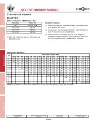
HORSEPOWER METHOD OF SELECTION<br />
Step 1: Determine Service Factor - See Table 2 for<br />
electric motor, hydraulic motor, steam turbine or gas<br />
turbine driven applications operating up to 10 hours per<br />
day or over 10 hours per day. If the application is engine<br />
driven, refer to Table 1 to convert the service factor<br />
obtained from Table 2 to the service factor required for<br />
engine driven applications. Service factor<br />
re<strong>com</strong>mendations are minimum. (For extreme shock or<br />
high energy loads which must be absorbed, as when<br />
stalling, or for power sources not listed, consult DODGE for<br />
special consideration.)<br />
Step 2: Calculate Equivalent Horsepower - Multiply the<br />
actual horsepower to be transmitted by the service factor<br />
obtained from Step 1.<br />
CAUTION: Instantaneous gear loading is limited to<br />
200% of the reducer rating. Do not allow<br />
starting load or other peak loads to<br />
exceed this value. Failure to observe this<br />
precaution could result in damage to, or<br />
destruction of, the equipment.<br />
Step 3: Calculate Required Ratio - Divide the high speed<br />
shaft rpm by the low speed shaft rpm.<br />
Step 4: Determine Unit Size and Ratio - Refer to the<br />
horsepower tables on pages G3-60, G3-62 and G3-66.<br />
From the high speed input shaft rpm in the left hand<br />
column and desired ratio and output speed in the next two<br />
columns, trace right into the table and find the horsepower<br />
rating equal to or greater than the equivalent horsepower<br />
obtained from Step 2. (When the required input speed falls<br />
between those tabulated, use straight line interpolation to<br />
determine the unit rating.)<br />
Step 5: Check Thermal Ratings - When the horsepower<br />
rating of the reducer selected from Step 4 falls in the<br />
shaded area, <strong>com</strong>pare the actual horsepower required<br />
(without service factor) with the thermal horsepower<br />
capacity by referring to the thermal horsepower rating<br />
tables on pages G3-68 and G3-69. If the actual transmitted<br />
horsepower exceeds the thermal capacity, an auxiliary<br />
cooling fan or a heat exchanger may be added to provide<br />
additional thermal capacity or a larger reducer may be<br />
required.<br />
NOTE: On applications where the continuous running<br />
time never exceeds three hours and the idle time<br />
is equal to or greater than the running time,<br />
thermal limitations can be disregarded and the<br />
unit operated at loads up to the listed mechanical<br />
rating modified by applicable service factors.<br />
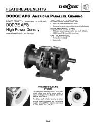
FEATURES/BENEFITS<br />
PAGE G3-3<br />
NOMENCLATURE<br />
PAGE G3-6<br />
G3-57<br />
Step 6: Check Overhung and Thrust Loads - Refer to<br />
the Overhung Load explanation on page G3-59. Overhung<br />
loads may be imposed on the input or output shafts when<br />
connected by means other than a coupling. If overhung<br />
loads are present, refer to the method and example for<br />
calculating overhung loads.<br />
External thrust loads may exist in applications such as<br />
agitators, mixers and similar equipment. Calculate the<br />
direction and magnitude of the thrust as well as the<br />
direction of the shaft rotation and consult DODGE.<br />
Step 7: Variable Speed Applications - When mounting<br />
variable speed AC or DC motors, consult the guidelines on<br />
pages G3-81 and G3-82.<br />
Step 8: Check Dimensions - See applicable pages for<br />
dimensions, weights, part numbers and instructions on how<br />
to order.<br />
TORQUE METHOD OF SELECTION<br />
Determine service factor, equivalent torque and unit size<br />
using the same steps as outlined above for the horsepower<br />
method, exce<strong>pt</strong> in Step 4 refer to the torque tables on<br />
pages G3-61, G3-64 and G3-67. Interpolate for speeds not<br />
listed. When ratings are shown in the shaded area, convert<br />
the required torque without service factor to horsepower by<br />
using the following formula:<br />
Horsepower =<br />
and <strong>com</strong>pare the <strong>com</strong>puted results with the thermal<br />
capacities shown in Table 20, page G3-68 and G3-69.<br />
EXAMPLES OF SELECTION<br />
Horsepower Method<br />
A centrifugal pump operating at 230 rpm is driven by a 200<br />
horsepower 1750 rpm motor. The duty cycle is 24 hours<br />
per day. Both the input and output reducer shafts are<br />
coupling connected.<br />
Step 1: Determine Service Factor - From Table 2,<br />
Service Factors, locate “Pumps - Centrifugal” and under<br />
the column headed “10+ Hrs/Day Service” find the Service<br />
Factor which is 1.25.<br />
Step 2: Calculate Equivalent Horsepower - Multiply the<br />
motor horsepower by the service factor (200 x 1.25 = 250)<br />
to get the equivalent horsepower of 250.<br />
Step 3: Calculate Required Ratio - Divide the high speed<br />
shaft rpm by the low speed shaft rpm (1750 / 230 = 7.6) to<br />
get the required ratio of 7.6:1.<br />
EASY SELECTION<br />
PAGE G3-7<br />
Torque (lb-in) x Low Speed Shaft rpm<br />
63025<br />
SELECTION/DIMENSIONS<br />
PAGE G3-23<br />
TIGEAR-2 MAXUM Concentric Reducer<br />
TORQUE-ARM<br />
TORQUE-ARM II<br />
Gearing Reference Guide
Gearing Reference Guide<br />
TORQUE-ARM II<br />
TORQUE-ARM<br />
MAXUM Concentric Reducer<br />
TIGEAR-2<br />
<strong>ENGINEERING</strong>/<strong>TECHNICAL</strong><br />
MAXUM Concentric Reducer<br />
Step 4: Determine Unit Size and Ratio - Locate the<br />
horsepower table for 1750 high speed shaft rpm(Table 14,<br />
page G3-60). Trace down the ratio column to the closest<br />
nominal ratio to the 7.6:1 required ratio and find 7.59:1<br />
ratio. Trace to the right until the horsepower equals or<br />
exceeds the calculated equivalent horsepower of 250 and<br />
find 323 horsepower listed under a MAXUM size 7 reducer.<br />
Step 5: Check Thermal Ratings - Because the 323<br />
mechanical horsepower rating for the MAXUM size 7<br />
reducer fell in the shaded area, the thermal capacity must<br />
be checked. Refer to the thermal horsepower rating tables<br />
on page G3-68. Locate the table for 1750 high speed shaft<br />
rpm and find the thermal ratings for the MAXUM size 7<br />
reducer. Note that the thermal rating without a fan is 150<br />
horsepower and that the thermal rating with a fan is 273<br />
horsepower. When a dash (-) is shown, the dash means<br />
that the thermal capacity exceeds the mechanical capacity.<br />
Since the actual transmitted horsepower of 200 exceeds<br />
the 150 thermal rating without a fan, an auxiliary cooling<br />
fan is required.<br />
Step 6: Check Overhung and Thrust Loads - Since both<br />
shafts are coupling connected, overhung or thrust loads<br />
are not applied.<br />
Step 7: Variable Speed Applications - Since this is a<br />
constant speed application, variable speed does not apply.<br />
Step 8: Check Dimensions - Refer to the specifications/<br />
dimensions page G3-29 for DODGE MAXUM size 7<br />
reducers. The part number for the reducer is 299140 and<br />
for the auxiliary cooling fan is 299523. The exact ratio of<br />
the reducer is given in Table 24, page G3-74 and is<br />
7.527:1.<br />
TORQUE METHOD<br />
Running 10 hours a day, a scum breaker for a sewage<br />
disposal system requires 51,350 lb-in of torque at 230 rpm<br />
and has an overhung load of 6,710 pounds on the low<br />
speed shaft. The overhung load is located 4inches out from<br />
the reducer on the usable shaft extension. The motor<br />
speed is 1170 rpm and is coupling connected.<br />
Step 1: Determine Service Factor - From Table 2,<br />
Service Factors, locate “Sewage Disposal - Scum<br />
Breakers” and under the column headed “3-10 Hrs/Day<br />
Service” locate the service factor which is 1.50.<br />
Step 2: Calculate Equivalent Torque - Multiply the<br />
system torque of 51,350 by the service factor of 1.50<br />
FEATURES/BENEFITS<br />
PAGE G3-3<br />
NOMENCLATURE<br />
PAGE G3-6<br />
G3-58<br />
(51,350 x 1.50 = 77,025) to get 77,025 lb-in equivalent<br />
torque.<br />
Step 3: Calculate Required Ratio - Divide the high speed<br />
shaft rpm by the low speed shaft rpm (1170 / 230 = 5.09) to<br />
get the required ratio of 5.09:1.<br />
Step 4: Determine Unit Size and Ratio - Locate the<br />
torque table for 1170 high speed shaft rpm (Table 17, page<br />
G3-64). Trace down the ratio column to the closest nominal<br />
ratio to the 5.09:1 required ratio and find 5.06:1 ratio. Trace<br />
to the right until the torque equals or exceeds the<br />
calculated equivalent torque of 77,025 and find 77,700<br />
listed under a MAXUM size 7 reducer.<br />
Step 5: Check Thermal Ratings - Because the 77,700<br />
mechanical rating falls in the shaded area, the thermal<br />
ratings must be checked. First, convert the required torque<br />
without service factor (51,350) to horsepower at 230 rpm<br />
as follows:<br />
Horsepower = 510350 X 230 = 187 hp<br />
63025<br />
Locate the table for the thermal horsepower ratings at 1170<br />
high speed shaft rpm and find the MAXUM size 7 reducer<br />
with a 5.06 ratio. Since the 187 calculated horsepower<br />
exceeds the thermal rating shown without a fan, an<br />
auxiliary cooling fan is required.<br />
Step 6: Check Overhung and Thrust Loads - An<br />
overhung load of 6,710 pounds is on the low speed shaft. It<br />
must first be adjusted for it’s position on the shaft. Turn to<br />
Table 22, page G3-71 load location factors for low speed<br />
shafts and locate the 4 inch distance in the left hand<br />
column. Under the MAXUM 7 column find the load location<br />
factor of 1.06. Multiply the 6,710 overhung load by this<br />
factor (6,710 x 1.06 = 7,113) to get an equivalent overhung<br />
load of 7,113 pounds. Now turn to the output shaft<br />
overhung load Table 24, page G3-74 and locate 230 low<br />
speed shaft rpm in the left column. Trace right to the<br />
MAXUM size 7 reducer and find the overhung load<br />
capacity of 7,480 pounds. Since the capacity exceeds the<br />
equivalent overhung load, the selection is acce<strong>pt</strong>able.<br />
Step 7: Variable Speed Applications - Since this is a<br />
constant speed application, variable speed does not apply.<br />
Step 8: Check Dimensions - Refer to the specifications/<br />
dimensions page G3-29 for DODGE MAXUM size 7<br />
reducers. The part number for the reducer is 299138 and<br />
for the auxiliary cooling fan is 299523. The exact ratio of<br />
the reducer is given in Table 25 and is 5.065:1.<br />
EASY SELECTION<br />
PAGE G3-7<br />
SELECTION/DIMENSIONS<br />
PAGE G3-23
<strong>ENGINEERING</strong>/<strong>TECHNICAL</strong><br />
MAXUM Concentric Reducer<br />
THRUST AND OVERHUNG LOADS-<br />
HOW TO CALCULATE<br />
Thrust Loads as defined here are external axial forces<br />
applied to the input or output shafts. They may exist in<br />
applications such as agitators, mixers and similar<br />
equipment. Calculate the direction and magnitude of the<br />
thrust load, determine the direction of shaft rotation and<br />
consult DODGE.<br />
Overhung Loads as defined here are external radial forces<br />
applied to the input or output shafts. They may occur in any<br />
angular position and at any distance out on the shaft from<br />
the reducer. Overhung loads may be calculated by the use<br />
of the following formula:<br />
OHL = 126,000 x hp x Fc x Lf<br />
PD x rpm<br />
Where: OHL = Overhung Load (lbs.).<br />
hp = Horsepower.<br />
Fc = Load Connection Factor.<br />
(See Table 13 below)<br />
Lf = Load Location Factor.<br />
(See Table 23 for High Speed Shafts)<br />
(See Table 24 for Low Speed Shafts)<br />
PD = Pitch Diameter of the Item Mounted<br />
on the Shaft (inches).<br />
rpm = Speed of Shaft with Overhung Load<br />
on it in Revolutions Per Minute.<br />
(Interpolate for shaft speeds not listed)<br />
Use the above formula to calculate the overhung load on<br />
the shaft. Compare the calculated OHL results with the<br />
values published for the reducer shaft and condition. If the<br />
calculated OHL results exceed the published values,<br />
consult DODGE or consider a larger size reducer.<br />
Location of Load Centerline - To minimize the affects of<br />
overhung loads and to increase bearing life, the centerline<br />
of the overhung load should always be located as close to<br />
the reducer oil seal as possible. For many applications the<br />
unit will ac<strong>com</strong>modate more overhung load than is<br />
published. Overhung load ratings have been established<br />
for the most unfavorable <strong>com</strong>bination of conditions that will<br />
be encountered.<br />
Overhung Loads - Examples<br />
High Speed Shaft Example - A MAXUM size 4 reducer<br />
with a 47.08:1 ratio is driven by a 1750 rpm 71/2 hp electric<br />
motor through a set of V-Belts at 870 rpm of the high speed<br />
shaft. The V-Belt drive consists of a 4.0” PD driver<br />
(2A3.6B4.0-1610) and a 8.6” PD driven sheave<br />
(2A8.2B8.6-2517). The driven sheave is mounted as close<br />
to the reducer oil seal as possible while allowing 1/4” for a<br />
guard thereby making the centerline of the belt pull 1.125”<br />
out from the reducer on the high speed shaft.<br />
FEATURES/BENEFITS<br />
PAGE G3-3<br />
NOMENCLATURE<br />
PAGE G3-6<br />
G3-59<br />
High Speed Shaft Calculation - Using the OHL equation<br />
previously given and substituting for the values as follows:<br />
hp = 7.5 (Motor Horsepower)<br />
Fc = 1.5 (From Table 13 for V-Belts)<br />
Lf = 0.975 (From Table 21 for MAXUM size 4<br />
at 1.125,)<br />
PD = 8.6 (Driven sheave pitch diameter)<br />
rpm = 870 (High speed shaft rpm)<br />
OHL = 126,000 x 7.5 x 1.5 x 0.975 = 185 pounds<br />
8.6 x 870<br />
Turn to Table 23, High Speed Shaft Overhung Load, and in<br />
the left hand column locate 870 rpm and in the ratio column<br />
locate the 47.08 ratio. Trace right to the MAXUM size 4 and<br />
note that the High Speed Shaft Overhung Load capacity is<br />
540 pounds. Since the 540 pound capacity exceeds the<br />
calculated overhung load of 185 pounds, the overhung<br />
load capacity is acce<strong>pt</strong>able.<br />
Low Speed Shaft Example - A MAXUM size 6 reducer is<br />
used to drive a uniformly loaded belt conveyor 24 hours per<br />
day. The reducer is driven by a 50 hp, 1750 rpm, electric<br />
motor coupled to the high speed shaft. The low speed shaft<br />
is rotating at 83.6 rpm and has a 160BTL26-3535 single<br />
strand sprocket with an oil tight chain casing mounted on it.<br />
The sprocket has a pitch diameter of 16.592 inches and the<br />
centerline of the teeth is located 4 inches out on the shaft.<br />
Low Speed Calculation - Using the OHL equation<br />
previously given and substituting for the values as follows:<br />
hp = 50.0 (Motor Horsepower)<br />
Fc = 1.0 (From Table 13 for Sprockets)<br />
Lf = 1.11 (From Table 22 for MAXUM size<br />
6 at 4,)<br />
PD = 16.592 (Driving sprocket pitch diameter)<br />
rpm = 83.6 (Low speed shaft rpm)<br />
OHL =<br />
126,000 x 50.0 x 1.0 x 1.11<br />
= 5041 pounds<br />
16.592 x 83.6<br />
Turn to Table 24, page G3-74, Low Speed Shaft Overhung<br />
Load, and in the left hand column locate the low speed<br />
shaft speed of 83.6 rpm. Trace right to the MAXUM size 6<br />
and note that the low speed shaft overhung load capacity is<br />
8250 pounds. Since the 8025 pound capacity exceeds the<br />
calculated overhung load of 5041 pounds, the overhung<br />
load capacity is acce<strong>pt</strong>able.<br />
Table 13: Load Connection Factors - Fc<br />
Drive Type Fc<br />
Roller Chain Sprocket 1.0<br />
Machined Pinion or Gear 1.25<br />
Synchronous Belt 1.3<br />
V-Belt 1.5<br />
V-Ribbed Belt 1.7<br />
Flat Belt 2.5<br />
EASY SELECTION<br />
PAGE G3-7<br />
SELECTION/DIMENSIONS<br />
PAGE G3-23<br />
TIGEAR-2 MAXUM Concentric Reducer<br />
TORQUE-ARM<br />
TORQUE-ARM II<br />
Gearing Reference Guide
Gearing Reference Guide<br />
TORQUE-ARM II<br />
TORQUE-ARM<br />
MAXUM Concentric Reducer<br />
TIGEAR-2<br />
<strong>ENGINEERING</strong>/<strong>TECHNICAL</strong><br />
MAXUM Concentric Reducer<br />
Table 14: 1750, 1450 RPM Input - Input Horsepower Ratings<br />
High<br />
Speed<br />
Shaft<br />
RPM<br />
AGMA<br />
Nominal<br />
Ratio<br />
FEATURES/BENEFITS<br />
PAGE G3-3<br />
Approx.<br />
Low Speed<br />
Shaft RPM<br />
Unit<br />
Red.<br />
DOUBLE<br />
TRIPLE<br />
DOUBLE<br />
TRIPLE<br />
NOMENCLATURE<br />
PAGE G3-6<br />
G3-60<br />
Rating Data @ 1.0 Service Factor<br />
for MAXUM unit size of:<br />
1 2 3 4 5 6 7 9 10 11 12<br />
2.25 777.8<br />
32.8 52.8 84.8 127 183 248<br />
2.75 636.4 30.1 47.2 81.9 122 165 224<br />
3.37 519.3 25.7 42.4 70.9 109 147 199<br />
4.13 423.7 31.9 52.8 73.4 123 184 221<br />
5.06 345.8 28.2 47.2 65.3 111 165 197 402 506 789 1111 1602<br />
6.20 282.3 25.1 42.4 57.9 97.3 146 174 345 468 699 1000 1428<br />
7.59 230.6 22.0 39.2 50.0 86.0 127 153 323 417 613 884 1284<br />
9.30 188.2 18.8 32.5 44.1 75.8 111 135 270 367 538 790 1105<br />
11.39 153.6 15.8 27.6 40.0 66.2 95.4 119 230 325 477 690 964<br />
13.95 125.4 13.2 22.9 34.1 58.4 78.3 102 190 283 418 604 814<br />
17.09 102.4 11.1 19.2 30.1 51.0 63.9 91.4 156 247 370 531 696<br />
1750 20.93 83.6 9.15 16.0 25.6 43.1 53.0 79.7 132 216 319 458 596<br />
25.63 68.3 7.58 13.5 21.7 34.7 43.5 71.0 108 189 277 375 493<br />
31.39 55.8<br />
6.53 11.6 18.1 30.1 35.2 57.4 87.5 163 233 301 403<br />
38.44 45.5 5.44 9.53 15.0 25.1 30.9 50.0 76.8 138 204 272 346<br />
47.08 37.2 4.52 7.90 12.6 21.0 26.8 43.6 65.0 114 173 228 291<br />
57.67 30.4 3.72 6.50 10.5 17.6 22.3 36.2 54.9 94.2 141 189 242<br />
70.62 24.8 3.07 5.41 8.77 14.1 18.3 30.8 45.8 78.2 116 158 198<br />
86.50 20.2 2.56 4.47 7.28 11.8 14.6 25.1 37.7 63.9 100 131 164<br />
105.90 16.5 2.12 3.64 5.95 9.90 11.9 20.0 31.8 52.7 81.7 108 134<br />
129.70 13.5 1.76 3.00 4.96 8.21 9.7 16.9 26.5 43.7 67.2 90.3 112<br />
158.90 11.0 1.44 2.45 4.09 6.84 8.05 13.8 21.5 36.3 56.1 75.1 93.1<br />
194.60 9.0 1.19 2.03 3.45 5.38 6.60 11.6 17.9 30.1 46.1 62.5 75.7<br />
2.25 644.4<br />
28.3 46.3 73.4 106 154 218<br />
2.75 527.3 26.0 41.4 70.8 103 138 196<br />
3.37 430.3 22.2 37.2 61.3 92.2 124 175<br />
4.13 351.1 28.0 46.3 64.4 106 161 194<br />
5.06 286.6 24.7 41.4 57.2 96.9 144 173 349 427 692 974 1404<br />
6.20 233.9 22.0 37.2 50.7 85.3 128 153 300 399 613 877 1252<br />
7.59 191.0 18.9 33.4 43.9 75.4 112 134 275 365 538 775 1126<br />
9.30 155.9 15.9 27.7 38.6 66.4 96.7 119 231 322 471 693 961<br />
11.39 127.3 13.4 23.5 34.5 58.1 80.9 104 195 285 418 605 830<br />
13.95 103.9 11.2 19.5 29.9 51.2 66.3 89.6 162 248 366 529 700<br />
17.09 84.8 9.34 16.3 26.0 43.2 54.2 80.1 132 216 325 466 601<br />
1450 20.93 69.3 7.72 13.5 21.6 36.4 44.9 69.9 112 189 280 389 506<br />
25.63 56.6 6.39 11.3 18.3 29.3 36.9 62.2 92.0 163 242 324 416<br />
31.39 46.2<br />
5.50 9.76 15.4 25.2 30.9 50.3 76.7 142 205 263 354<br />
38.44 37.7 4.58 8.02 12.6 21.2 27.1 42.8 67.3 116 172 230 291<br />
47.08 30.8 3.80 6.62 10.6 17.6 22.5 36.7 54.8 95.5 146 193 245<br />
57.67 25.1 3.13 5.44 8.72 14.8 18.7 30.5 46.2 79.0 119 159 203<br />
70.62 20.5 2.58 4.52 7.38 11.8 15.3 25.9 38.5 65.5 98.0 133 166<br />
86.50 16.8 2.15 3.73 6.12 9.94 12.3 21.0 31.8 53.5 84.3 110 137<br />
105.90 13.7 1.78 3.04 5.00 8.31 9.97 16.8 26.7 44.1 68.7 90.9 112<br />
129.70 11.2 1.48 2.50 4.17 6.89 8.14 14.2 22.2 36.5 56.5 76.0 94.0<br />
158.90 9.1 1.21 2.04 3.43 5.75 6.75 11.6 18.0 30.4 47.2 63.0 77.9<br />
194.60 7.5 1.00 1.69 2.89 4.51 5.54 9.70 15.0 25.1 38.7 52.5 63.3<br />
Mechanical HP ratings shown in shaded areas exceed the unit thermal HP ratings.<br />
Refer to Thermal HP Table 20, page G3-68.<br />
Sizes 1-3 discounted remaining sotck may be avaialble.<br />
EASY SELECTION<br />
PAGE G3-7<br />
SELECTION/DIMENSIONS<br />
PAGE G3-23
<strong>ENGINEERING</strong>/<strong>TECHNICAL</strong><br />
MAXUM Concentric Reducer<br />
Table 15: 1750, 1450 RPM Input - Output Torque Ratings (In. - Lb.)<br />
High<br />
Speed<br />
Shaft<br />
RPM<br />
AGMA<br />
Nominal<br />
Ratio<br />
FEATURES/BENEFITS<br />
PAGE G3-3<br />
Approx.<br />
Low Speed<br />
Shaft RPM<br />
Unit<br />
Red.<br />
DOUBLE<br />
TRlPLE<br />
DOUBLE<br />
NOMENCLATURE<br />
PAGE G3-6<br />
Rating Data @ 1.0 Service Factor<br />
for MAXUM unit size of (multiply value shown by 1000):<br />
1 2 3 4 5 6 7 9 10 11 12<br />
2.25 777.8<br />
2.55 4.12 6.63 9.81 14.3 19.5<br />
2.75 636.4 2.92 4.57 7.82 11.3 15.7 21.5<br />
3.37 519.3 3.03 4.95 8.25 12.5 17.0 23.4<br />
4.13 423.7 4.52 7.50 10.6 17.5 26.2 31.6<br />
5.06 345.8 4.95 8.31 11.5 19.0 28.5 34.3 70.4 89.3 135 196 282<br />
6.20 282.3 5.36 9.00 12.4 20.7 30.7 37.2 73.1 99.5 148 212 307<br />
7.59 230.6 5.81 10.2 13.5 22.6 33.1 40.5 84.1 108 161 231 332<br />
9.30 188.2 6.03 10.5 14.5 24.3 35.4 43.4 86.0 117 175 248 356<br />
11.39 153.6 6.17 10.8 15.7 26.2 37.5 46.6 89.1 126 187 269 377<br />
13.95 125.4 6.31 11.1 16.6 28.1 37.9 50.4 91.6 136 201 290 394<br />
17.09 102.4 6.45 11.4 17.8 30.0 37.9 53.3 94.3 146 214 310 407<br />
1750 20.93 83.6 6.59 11.7 18.7 30.6 37.9 57.0 96.3 157 231 330 425<br />
25.63 68.3 6.72 11.9 19.0 31.4 37.9 60.5 95.6 167 248 328 436<br />
31.39 55.8<br />
6.84 12.2 19.1 32.1 37.4 62.3 90.4 169 250 319 427<br />
38.44 45.5 6.96 12.4 19.8 32.5 40.5 68.0 98.5 178 268 355 453<br />
47.08 37.2 7.08 12.6 20.1 33.3 43.0 70.1 105 181 273 362 460<br />
57.67 30.4 7.20 12.8 20.7 33.7 43.0 71.4 107 184 279 370 467<br />
70.62 24.8 7.32 12.9 20.8 34.3 43.0 72.4 108 186 285 377 474<br />
86.50 20.2 7.43 13.0 21.1 34.8 43.0 73.2 110 188 289 384 480<br />
105.90 16.5 7.53 13.1 21.4 35.3 43.0 73.2 112 190 294 391 486<br />
129.70 13.5 7.64 13.3 21.8 35.9 43.0 73.2 114 192 300 397 491<br />
158.90 11.0 7.75 13.3 22.1 36.2 43.0 73.2 116 194 304 405 496<br />
194.60 9.0 7.85 13.4 22.3 36.2 43.0 73.2 117 196 309 410 502<br />
2.25 644.4<br />
2.66 4.36 6.93 9.81 14.5 20.7<br />
2.75 527.3 3.04 4.84 8.16 11.5 15.9 22.7<br />
3.37 430.3 3.16 5.24 8.61 12.8 17.2 24.7<br />
4.13 351.1 4.78 7.93 11.2 18.2 27.7 33.5<br />
5.06 286.6 5.24 8.79 12.1 20.1 30.1 36.3 73.8 90.9 143 208 298<br />
6.20 233.9 5.67 9.52 13.1 21.9 32.5 39.3 76.5 103 156 225 325<br />
7.59 191.0 6.02 10.4 14.3 23.9 35.1 42.9 86.5 114 170 244 351<br />
9.30 155.9 6.16 10.8 15.4 25.7 37.4 45.9 89.0 124 185 262 374<br />
11.39 127.3 6.30 11.1 16.3 27.8 38.4 49.3 91.3 133 198 285 392<br />
13.95 103.9 6.44 11.4 17.6 29.7 38.8 53.3 93.8 144 213 307 409<br />
17.09 84.8 6.58 11.7 18.6 30.6 38.8 56.4 96.4 155 227 328 424<br />
1450 20.93 69.3 6.71 11.9 19.0 31.2 38.8 60.3 98.4 166 245 338 435<br />
25.63 56.6 6.84 12.2 19.4 32.0 38.8 64.1 98.6 174 262 342 444<br />
31.39 46.2<br />
6.96 12.4 19.7 32.5 39.6 65.9 95.7 178 265 337 451<br />
38.44 37.7 7.07 12.6 20.1 33.1 42.8 70.2 104 181 273 362 460<br />
47.08 30.8 7.19 12.8 20.4 33.7 43.6 71.3 107 183 278 369 467<br />
57.67 25.1 7.31 12.9 20.8 34.2 43.6 72.5 108 186 284 376 473<br />
˙70.62 20.5 7.42 13.0 21.1 34.8 43.6 73.6 110 188 289 383 480<br />
86.50 16.8 7.53 13.1 21.4 35.3 43.6 74.2 112 190 294 390 486<br />
105.90 13.7 7.63 13.2 21.7 35.8 43.6 74.2 114 192 299 397 491<br />
129.70 11.2 7.74 13.3 22.0 36.3 43.6 74.2 115 194 304 403 496<br />
158.90 9.1 7.84 13.4 22.3 36.7 43.6 74.2 117 196 308 410 501<br />
194.60 7.5 7.95 13.5 22.6 36.7 43.6 74.2 119 197 313 416 506<br />
Torque ratings shown in shaded areas exceed the unit thermal HP ratings.<br />
Convert torque (without service factor) to HP per the formula given on page G3-58.<br />
Refer to Thermal HP Table 20, page G3-68.<br />
Sizes 1-3 discounted remaining sotck may be avaialble.<br />
TRlPLE<br />
G3-61<br />
EASY SELECTION<br />
PAGE G3-7<br />
SELECTION/DIMENSIONS<br />
PAGE G3-23<br />
TIGEAR-2 MAXUM Concentric Reducer<br />
TORQUE-ARM<br />
TORQUE-ARM II<br />
Gearing Reference Guide
Gearing Reference Guide<br />
TORQUE-ARM II<br />
TORQUE-ARM<br />
MAXUM Concentric Reducer<br />
TIGEAR-2<br />
<strong>ENGINEERING</strong>/<strong>TECHNICAL</strong><br />
MAXUM Concentric Reducer<br />
Table 16: 1170, 870, 720 RPM Input - Input Horsepower Ratings<br />
High<br />
Speed<br />
Shaft<br />
RPM<br />
AGMA<br />
Nominal<br />
Ratio<br />
FEATURES/BENEFITS<br />
PAGE G3-3<br />
Approx.<br />
Low Speed<br />
Shaft RPM<br />
Unit<br />
Red.<br />
DOUBLE<br />
TRlPLE<br />
DOUBLE<br />
TRlPLE<br />
NOMENCLATURE<br />
PAGE G3-6<br />
G3-62<br />
Rating Data @ 1.0 Service Factor<br />
for MAXUM unit size of:<br />
1 2 3 4 5 6 7 9 10 11 12<br />
2.25 520.0<br />
23.9 39.8 62.2 85.2 126 182<br />
2.75 425.5 22.0 35.6 60.0 84.7 113 163<br />
3.37 347.2 18.8 32.0 51.9 75.5 101 144<br />
4.13 283.3 23.9 39.8 55.4 85.2 139 167<br />
5.06 231.2 21.3 35.6 49.2 83.4 124 149 297 351 595 838 1209<br />
6.20 188.7 18.8 32.0 43.6 73.4 110 131 255 329 527 755 1077<br />
7.59 154.2 15.6 27.8 37.7 64.8 96.1 115 229 304 463 667 969<br />
9.30 125.8 13.2 23.0 33.2 57.1 80.1 102 192 276 406 596 816<br />
11.39 102.7 11.1 19.5 29.7 50.0 66.9 89.4 162 245 360 520 699<br />
13.95 83.9 9.23 16.1 25.6 42.7 54.3 77.1 134 213 315 455 589<br />
17.09 68.5 7.69 13.4 21.5 35.6 44.4 68.9 109 186 279 387 499<br />
1170 20.93 55.9 6.35 11.1 17.8 30.0 36.8 60.1 92.4 161 241 322 417<br />
25.63 45.6 5.26 9.33 15.1 24.1 30.2 52.5 76.8 135 200 270 342<br />
31.39 37.3<br />
4.52 8.02 12.7 20.8 26.6 43.2 66.0 116 171 227 291<br />
38.44 30.4 3.76 6.56 10.4 17.4 22.4 35.2 55.5 95.2 142 189 239<br />
47.08 24.9 3.12 5.40 8.68 14.5 18.3 30.2 45.1 78.1 120 159 200<br />
57.67 20.3 2.57 4.43 7.15 12.1 15.2 25.0 38.0 64.5 97.8 131 166<br />
70.62 16.6 2.12 3.68 6.05 9.7 12.5 21.2 31.6 53.5 80.5 110 136<br />
86.50 13.5 1.76 3.04 5.01 8.15 9.97 17.1 26.0 43.6 69.3 90.5 112<br />
105.90 11.0 1.46 2.47 4.09 6.81 8.10 13.6 21.9 35.9 56.4 74.6 91.8<br />
129.70 9.0 1.21 2.03 3.41 5.64 6.61 11.5 18.2 29.7 46.3 62.3 76.7<br />
158.90 7.4 0.990 1.66 2.81 4.67 5.49 9.4 14.8 24.7 38.7 51.6 63.5<br />
194.60 6.0 0.815 1.38 2.37 3.67 4.5 7.88 12.3 20.4 31.7 43.1 51.6<br />
2.25 386.7<br />
18.9 32.4 49.3 63.4 95.6 139<br />
2.75 316.4 17.4 28.9 47.5 63.4 86.2 124<br />
3.37 258.2 14.8 26.0 41.1 57.3 77.0 109<br />
4.13 210.7 18.9 32.4 45.0 63.4 113 136<br />
5.06 171.9 17.2 28.9 40.0 63.4 101 121 236 269 484 681 982<br />
6.20 140.3 14.5 25.6 35.5 59.4 89.6 107 203 252 429 613 875<br />
7.59 114.6 12.0 21.5 30.7 52.7 74.2 93.5 177 232 376 542 769<br />
9.30 93.5 10.1 17.7 27.0 46.4 61.6 82.9 148 211 330 484 643<br />
11.39 76.4 8.47 15.0 23.9 38.9 50.5 72.7 124 190 293 423 548<br />
13.95 62.4 7.06 12.4 19.6 32.7 41.0 62.7 103 173 256 354 453<br />
17.09 50.9 5.88 10.3 16.4 27.2 33.5 56.0 83.7 148 227 298 381<br />
870 20.93 41.6 4.85 8.49 13.6 22.9 27.8 47.2 70.7 123 186 247 318<br />
25.63 33.9 4.01 7.11 11.5 18.4 22.8 39.6 59.1 102 153 207 260<br />
31.39 27.7<br />
3.44 6.07 9.66 15.8 20.7 33.0 51.6 88.2 131 175 221<br />
38.44 22.6 2.86 4.95 7.91 13.2 16.8 26.8 42.3 72.1 108 145 181<br />
47.08 18.5 2.37 4.07 6.60 11.0 13.7 23.0 34.3 59.1 91.5 121 152<br />
57.67 15.1 1.95 3.34 5.44 9.21 11.4 19.0 28.9 48.7 74.6 100 126<br />
70.62 12.3 1.61 2.77 4.59 7.36 9.32 15.9 24.1 40.4 61.3 83.6 103<br />
86.50 10.1 1.33 2.28 3.80 6.18 7.46 12.8 19.8 32.9 52.7 68.9 84.7<br />
105.90 8.2 1.10 1.86 3.10 5.16 6.06 10.2 16.6 27.1 42.9 56.8 69.2<br />
129.70 6.7 0.914 1.52 2.59 4.23 4.95 8.62 13.8 22.4 35.2 47.4 57.8<br />
158.90 5.5 0.750 1.25 2.13 3.49 4.11 7.03 11.2 18.6 29.4 39.2 47.8<br />
194.60 4.5 0.617 1.03 1.79 2.74 3.37 5.89 9.3 15.4 24.1 32.7 38.8<br />
Mechanical HP ratings shown in shaded areas exceed the unit thermal HP ratings.<br />
Refer to Thermal HP Table 20, page G3-68.<br />
Sizes 1-3 discounted remaining sotck may be avaialble.<br />
EASY SELECTION<br />
PAGE G3-7<br />
SELECTION/DIMENSIONS<br />
PAGE G3-23
<strong>ENGINEERING</strong>/<strong>TECHNICAL</strong><br />
MAXUM Concentric Reducer<br />
Table 16: 1170, 870, 720 RPM Input - Input Horsepower Ratings (cont’d)<br />
High<br />
Speed<br />
Shaft<br />
RPM<br />
720<br />
AGMA<br />
Nominal<br />
Ratio<br />
FEATURES/BENEFITS<br />
PAGE G3-3<br />
Approx.<br />
Low Speed<br />
Shaft RPM<br />
Unit<br />
Red.<br />
DOUBLE<br />
TRlPLE<br />
NOMENCLATURE<br />
PAGE G3-6<br />
G3-63<br />
Rating Data @ 1.0 Service Factor<br />
for MAXUM unit size of:<br />
1 2 3 4 5 6 7 9 10 11 12<br />
2.25 320.0<br />
16.3 28.3 42.5 52.4 80.2 116<br />
2.75 261.8 14.9 25.3 40.9 52.4 72.3 104<br />
3.37 213.6 12.7 22.8 35.3 48.1 64.6 91.6<br />
4.13 174.3 16.3 28.3 39.4 52.4 95.4 119<br />
5.06 142.3 14.6 25.3 35.1 52.4 85.9 106 204 226 424 597 861<br />
6.20 116.1 12.3 21.7 31.1 50.0 75.9 93.6 175 212 375 537 765<br />
7.59 94.9 10.1 18.2 26.9 46.2 62.7 81.9 150 196 329 475 661<br />
9.30 77.4 8.51 15.0 23.5 39.6 52.0 72.6 125 178 289 424 550<br />
11.39 63.2 7.14 12.7 20.1 32.8 42.7 63.7 105 161 256 360 462<br />
13.95 51.6 5.94 10.4 16.5 27.5 34.6 54.9 86.7 151 224 300 381<br />
17.09 42.1 4.94 8.64 13.8 22.9 28.3 48.8 70.6 125 191 251 321<br />
20.93 34.4 4.07 7.14 11.4 19.3 23.5 39.9 59.6 103 157 208 267<br />
25.63 28.1 3.37 5.94 9.66 15.4 19.2 33.4 49.7 85.8 129 175 218<br />
31.39 22.9<br />
2.89 5.07 8.12 13.3 17.2 27.7 43.4 73.8 110 147 185<br />
38.44 18.7 2.40 4.13 6.64 11.1 14.0 22.5 35.6 60.3 91.0 122 152<br />
47.08 15.3 1.99 3.40 5.54 9.23 11.4 19.3 28.9 49.4 77.0 102 127<br />
57.67 12.5 1.63 2.78 4.56 7.73 9.46 15.8 24.3 40.7 62.7 84.0 105<br />
70.62 10.2 1.35 2.31 3.85 6.17 7.76 13.2 20.2 33.7 51.5 70.2 85.7<br />
86.50 8.3 1.12 1.90 3.19 5.18 6.22 10.7 16.6 27.4 44.2 57.8 70.8<br />
105.90 6.8 .925 1.55 2.60 4.31 5.05 8.5 13.9 22.6 35.9 47.6 57.8<br />
129.70 5.6 .765 1.27 2.16 3.52 4.12 7.18 11.6 18.7 29.5 39.7 48.2<br />
158.90 4.5 .628 1.04 1.78 2.91 3.42 5.86 9.38 15.5 24.6 32.9 39.9<br />
194.60 3.7 .516 .859 1.50 2.29 2.80 4.91 7.76 12.8 20.2 27.4 32.3<br />
Mechanical HP ratings shown in shaded areas exceed the unit thermal HP ratings.<br />
Refer to Thermal HP Table 20, page G3-68.<br />
Sizes 1-3 discounted remaining sotck may be avaialble.<br />
EASY SELECTION<br />
PAGE G3-7<br />
SELECTION/DIMENSIONS<br />
PAGE G3-23<br />
TIGEAR-2 MAXUM Concentric Reducer<br />
TORQUE-ARM<br />
TORQUE-ARM II<br />
Gearing Reference Guide
Gearing Reference Guide<br />
TORQUE-ARM II<br />
TORQUE-ARM<br />
MAXUM Concentric Reducer<br />
TIGEAR-2<br />
<strong>ENGINEERING</strong>/<strong>TECHNICAL</strong><br />
MAXUM Concentric Reducer<br />
Table 17: 1170, 870, 720 RPM Input - Output Torque Ratings (In. - Lb.)<br />
High<br />
Speed<br />
Shaft<br />
RPM<br />
AGMA<br />
Nominal<br />
Ratio<br />
FEATURES/BENEFITS<br />
PAGE G3-3<br />
Approx.<br />
Low Speed<br />
Shaft RPM<br />
Unit<br />
Red.<br />
DOUBLE<br />
TRlPLE<br />
DOUBLE<br />
TRlPLE<br />
NOMENCLATURE<br />
PAGE G3-6<br />
Rating Data @ 1.0 Service Factor<br />
for MAXUM unit size of (multiply value shown by 1000):<br />
1 2 3 4 5 6 7 9 10 11 12<br />
2.25 520.0<br />
2.79 4.65 7.28 9.81 14.7 21.4<br />
2.75 425.5 3.18 5.16 8.56 11.7 16.1 23.3<br />
3.37 347.2 3.30 5.58 9.03 13.0 17.5 25.2<br />
4.13 283.3 5.07 8.46 11.9 18.2 29.5 35.7<br />
5.06 231.2 5.59 9.38 12.9 21.4 32.1 38.7 77.7 92.8 153 221 318<br />
6.20 188.7 6.00 10.2 14.0 23.4 34.7 41.9 80.5 105 167 239 347<br />
7.59 154.2 6.18 10.8 15.3 25.5 37.4 45.7 89.1 118 182 261 374<br />
9.30 125.8 6.32 11.1 16.4 27.4 38.4 49.0 91.5 131 197 280 394<br />
11.39 102.7 6.45 11.4 17.4 29.6 39.3 52.6 93.8 142 211 304 409<br />
13.95 83.9 6.58 11.7 18.7 30.7 39.3 56.8 96.2 153 227 327 426<br />
17.09 68.5 6.71 11.9 19.0 31.3 39.3 60.1 98.7 165 242 338 436<br />
1170 20.93 55.9 6.85 12.2 19.4 31.9 39.3 64.3 101 175 261 347 444<br />
25.63 45.6 6.97 12.4 19.7 32.6 39.3 66.9 102 178 268 354 453<br />
31.39 37.3<br />
7.08 12.6 20.1 33.2 42.3 70.2 102 181 273 360 460<br />
38.44 30.4 7.20 12.8 20.5 33.7 43.9 71.6 106 184 279 370 468<br />
47.08 24.9 7.31 12.9 20.8 34.3 43.9 72.6 109 186 284 377 474<br />
57.67 20.3 7.42 13.0 21.1 34.8 43.9 73.8 110 188 289 384 480<br />
70.62 16.6 7.54 13.1 21.4 35.4 43.9 74.7 112 190 295 390 486<br />
86.5 13.5 7.64 13.2 21.7 35.9 43.9 74.7 114 192 299 397 491<br />
105.9 11.0 7.75 13.3 22.1 36.4 43.9 74.7 116 194 304 404 497<br />
129.7 9.0 7.85 13.4 22.4 36.9 43.9 74.7 117 196 309 410 501<br />
158.9 7.4 7.95 13.5 22.7 36.9 43.9 74.7 119 197 313 416 506<br />
194.6 6.0 8.05 13.6 22.9 36.9 43.9 74.7 121 199 318 422 511<br />
2.25 386.7<br />
2.97 5.09 7.77 9.81 15.00 21.9<br />
2.75 316.4 3.39 5.64 9.13 11.8 16.5 23.9<br />
3.37 258.2 3.51 6.10 9.61 13.2 17.9 25.8<br />
4.13 210.7 5.39 9.25 13.0 18.2 32.3 39.0<br />
5.06 171.9 6.10 10.2 14.2 21.9 35.1 42.3 83.3 95.4 167 242 348<br />
6.20 140.3 6.24 10.9 15.3 25.4 37.8 45.8 86.2 108 182 262 379<br />
7.59 114.6 6.39 11.2 16.7 27.8 38.8 50.0 92.6 121 199 285 400<br />
9.30 93.5 6.52 11.5 17.9 30.0 39.8 53.5 94.9 135 215 306 417<br />
11.39 76.4 6.65 11.8 18.8 31.0 39.9 57.5 97.1 148 231 332 431<br />
13.95 62.4 6.77 12.1 19.2 31.6 39.9 62.1 99.4 168 248 342 440<br />
17.09 50.9 6.90 12.3 19.6 32.2 39.9 65.7 102 176 264 350 448<br />
870 20.93 41.6 7.02 12.5 19.9 32.8 39.9 67.9 104 180 270 358 456<br />
25.63 33.9 7.15 12.7 20.3 33.5 39.9 67.9 106 182 276 365 464<br />
31.39 27.7<br />
7.25 12.8 20.6 34.0 44.2 72.0 107 184 281 373 470<br />
38.44 22.6 7.36 12.9 21.0 34.5 44.2 73.3 109 187 287 380 477<br />
47.08 18.5 7.47 13.1 21.3 35.0 44.2 74.3 111 189 291 387 483<br />
57.67 15.1 7.58 13.2 21.6 35.5 44.2 75.2 113 191 297 394 488<br />
70.62 12.3 7.69 13.3 21.9 36.2 44.2 75.2 115 193 302 400 494<br />
86.5 10.1 7.79 13.4 22.2 36.6 44.2 75.2 116 195 306 407 499<br />
105.9 8.2 7.89 13.5 22.5 37.1 44.2 75.2 118 197 311 413 504<br />
129.7 6.7 7.99 13.6 22.8 37.1 44.2 75.2 120 198 316 419 508<br />
158.9 5.5 8.09 13.7 23.1 37.1 44.2 75.2 121 200 320 425 512<br />
194.6 4.5 8.20 13.7 23.3 37.1 44.2 75.2 123 201 324 431 517<br />
Torque ratings shown in shaded areas exceed the unit thermal HP ratings.<br />
Convert torque (without service factor) to HP per the formula on page G3-58.<br />
Sizes 1-3 discounted remaining sotck may be avaialble.<br />
Refer to Thermal HP Table 20, page G3-68<br />
G3-64<br />
EASY SELECTION<br />
PAGE G3-7<br />
SELECTION/DIMENSIONS<br />
PAGE G3-23
<strong>ENGINEERING</strong>/<strong>TECHNICAL</strong><br />
MAXUM Concentric Reducer<br />
Table 17: 1170, 870, 720 RPM Input - Output Torque Ratings (In. - Lb.)<br />
High<br />
Speed<br />
Shaft<br />
RPM<br />
720<br />
AGMA<br />
Nominal<br />
Ratio<br />
FEATURES/BENEFITS<br />
PAGE G3-3<br />
Approx.<br />
Low Speed<br />
Shaft RPM<br />
Unit<br />
Red.<br />
DOUBLE<br />
NOMENCLATURE<br />
PAGE G3-6<br />
Rating Data @ 1.0 Service Factor<br />
for MAXUM unit size of (multiply value shown by 1000):<br />
1 2 3 4 5 6 7 9 10 11 12<br />
2.25 320.0<br />
3.09 5.38 8.08 9.81 15.3 22.2<br />
2.75 261.8 3.52 5.97 9.49 11.80 16.7 24.2<br />
3.37 213.6 3.64 6.46 10.0 13.4 18.1 26.1<br />
4.13 174.3 5.60 9.79 13.8 18.2 33.0 41.3<br />
5.06 142.3 6.24 10.8 15.0 21.9 36.1 44.8 86.9 97.1 177 256 368<br />
6.20 116.1 6.37 11.2 16.2 25.9 38.7 48.5 89.9 110 193 277 400<br />
7.59 94.9 6.52 11.5 17.6 29.4 39.7 52.9 94.8 123 210 302 415<br />
9.30 77.4 6.64 11.8 18.8 30.9 40.6 56.6 97.0 138 228 324 431<br />
11.39 63.2 6.77 12.0 19.2 31.6 40.8 60.9 99.1 151 244 342 439<br />
13.95 51.6 6.89 12.3 19.6 32.2 40.8 65.7 101 176 263 350 448<br />
17.09 42.1 7.01 12.5 19.9 32.8 40.8 69.2 104 180 269 357 456<br />
20.93 34.4 7.13 12.7 20.3 33.3 40.8 69.4 106 182 275 365 463<br />
25.63 28.1 7.25 12.8 20.6 34.0 40.8 69.4 107 185 281 372 470<br />
31.39 22.9<br />
7.36 12.9 20.9 34.5 44.5 73.1 109 187 286 379 476<br />
38.44 18.7 7.47 13.0 21.3 35.0 44.5 74.4 111 189 291 387 483<br />
47.08 15.3 7.57 13.2 21.6 35.5 44.5 75.4 113 191 296 393 488<br />
57.67 12.5 7.68 13.3 21.9 36.0 44.5 75.7 115 193 301 400 493<br />
70.62 10.2 7.79 13.4 22.2 36.6 44.5 75.7 116 195 306 406 499<br />
86.5 8.3 7.89 13.5 22.5 37.1 44.5 75.7 118 196 310 413 503<br />
105.9 6.8 7.98 13.6 22.8 37.4 44.5 75.7 120 198 315 419 508<br />
129.7 5.6 8.08 13.6 23.1 37.4 44.5 75.7 121 200 320 425 512<br />
158.9 4.5 8.19 13.7 23.3 37.4 44.5 75.7 123 201 324 431 516<br />
194.6 3.7 8.29 13.8 23.6 37.4 44.5 75.7 124 202 328 436 521<br />
Torque ratings shown in shaded areas exceed the unit thermal HP ratings.<br />
Convert torque (without service factor) to HP per the formula on page G3-58.<br />
Sizes 1-3 discounted remaining sotck may be avaialble.<br />
Refer to Thermal HP Table 20, page G3-68<br />
TRlPLE<br />
G3-65<br />
EASY SELECTION<br />
PAGE G3-7<br />
SELECTION/DIMENSIONS<br />
PAGE G3-23<br />
TIGEAR-2 MAXUM Concentric Reducer<br />
TORQUE-ARM<br />
TORQUE-ARM II<br />
Gearing Reference Guide
Gearing Reference Guide<br />
TORQUE-ARM II<br />
TORQUE-ARM<br />
MAXUM Concentric Reducer<br />
TIGEAR-2<br />
<strong>ENGINEERING</strong>/<strong>TECHNICAL</strong><br />
MAXUM Concentric Reducer<br />
Table 18: 580, 100 RPM Input - Input Horsepower Ratings<br />
High<br />
Speed<br />
Shaft<br />
RPM<br />
AGMA<br />
Nominal<br />
Ratio<br />
FEATURES/BENEFITS<br />
PAGE G3-3<br />
Approx.<br />
Low Speed<br />
Shaft RPM<br />
Unit<br />
Red.<br />
DOUBLE<br />
TRlPLE<br />
DOUBLE<br />
TRlPLE<br />
NOMENCLATURE<br />
PAGE G3-6<br />
G3-66<br />
Rating Data @ 1.0 Service Factor<br />
for MAXUM unit size of:<br />
1 2 3 4 5 6 7 9 10 11 12<br />
2.25 257.8<br />
13.7 24.4 35.8 42.2 65.6 95.2<br />
2.75 210.9 12.5 21.8 34.4 42.2 59.2 85.0<br />
3.37 172.1 10.7 19.6 29.7 39.3 52.9 75.0<br />
4.13 140.4 13.7 24.4 33.9 42.2 78.1 102.0<br />
5.06 114.6 12.0 21.2 30.1 42.2 70.3 90.9 172 186 358 513 739<br />
6.20 93.5 10.1 18.0 26.7 41.1 62.6 80.4 147 174 323 462 643<br />
7.59 76.4 8.35 15.1 23.1 38.5 51.7 70.4 124 161 283 408 553<br />
9.30 62.4 7.00 12.4 19.4 32.6 42.4 62.4 103 146 248 360 453<br />
11.39 50.9 5.86 10.4 16.5 27.0 34.6 54.7 86.6 132 220 297 380<br />
13.95 41.6 4.88 8.55 13.6 22.6 28.1 46.7 71.3 124 186 247 313<br />
17.09 33.9 4.06 7.08 11.3 18.8 22.9 39.7 58.0 102 158 207 263<br />
580 20.93 27.7 3.34 5.81 9.36 15.8 19.0 32.4 48.9 84.3 129 171 219<br />
25.63 22.6 2.76 4.83 7.92 12.6 15.6 27.1 40.8 70.0 106 144 179<br />
31.39 18.5<br />
2.36 4.12 6.65 10.9 13.9 22.70 35.60 60.2 90.2 121 151<br />
38.44 15.1 1.96 3.36 5.43 9.1 11.3 18.4 29.2 49.1 74.7 100 124<br />
47.08 12.3 1.63 2.76 4.53 7.55 9.25 15.7 23.6 40.2 63.1 83.5 104<br />
57.67 10.1 1.33 2.26 3.73 6.32 7.67 12.8 19.9 33.1 51.3 68.8 85.8<br />
70.62 8.2 1.10 1.87 3.14 5.05 6.29 10.7 16.5 27.4 42.1 57.5 69.7<br />
86.5 6.7 .912 1.54 2.60 4.23 5.04 8.64 13.6 22.3 36.2 47.3 57.5<br />
105.9 5.5 .755 1.25 2.12 3.49 4.09 6.89 11.4 18.3 29.4 38.9 47<br />
129.7 4.5 .625 1.03 1.77 2.85 3.34 5.82 9.47 15.2 24.1 32.5 39.2<br />
158.9 3.7 .512 .840 1.45 2.36 2.77 4.75 7.62 12.6 20.1 26.8 32.4<br />
194.6 3.0 .421 .697 1.22 1.85 2.27 3.98 6.29 10.4 16.5 22.4 26.3<br />
2.25 44.4<br />
2.36 4.20 7.28 11.3 16.4<br />
2.75 36.4 2.16 3.75 5.93 7.28 10.2 14.7<br />
3.37 29.7 1.84 3.38 5.12 6.77 9.1 12.9<br />
4.13 24.2 2.36 4.20 5.84 7.28 13.5 17.6<br />
5.06 19.8 2.07 3.65 5.20 7.28 12.1 15.7 29.7 32.1 61.8 88.4 127.5<br />
6.20 16.1 1.74 3.10 4.60 7.09 10.8 13.9 25.4 30.1 55.6 79.6 110.9<br />
7.59 13.2 1.44 2.60 3.98 6.63 8.92 12.1 21.3 27.8 48.8 70.4 95.3<br />
9.30 10.8 1.21 2.13 3.34 5.63 7.31 10.8 17.8 25.2 42.8 62.1 78.0<br />
11.39 8.8 1.01 1.79 2.85 4.65 5.96 9.43 14.9 22.8 38.0 51.2 65.5<br />
13.95 7.2 .84 1.47 2.34 3.90 4.84 8.06 12.3 21.4 32.0 42.6 53.9<br />
17.09 5.9 .70 1.22 1.96 3.25 3.96 6.84 10.0 17.6 27.2 35.7 45.3<br />
100 20.93 4.8 .58 1.00 1.61 2.72 3.28 5.58 8.44 14.5 22.2 29.6 37.7<br />
25.63 3.9 .48 .833 1.37 2.18 2.69 4.68 7.04 12.1 18.3 24.8 30.8<br />
31.39 3.2<br />
.408 .711 1.15 1.88 2.40 3.92 6.13 10.4 15.6 20.8 26.1<br />
38.44 2.6 .338 .579 .937 1.57 1.95 3.18 5.03 8.47 12.9 17.2 21.3<br />
47.08 2.1 .280 .476 .781 1.30 1.59 2.71 4.07 6.93 10.9 14.4 17.8<br />
57.67 1.7 .230 .389 .643 1.09 1.32 2.21 3.43 5.71 8.85 11.9 14.8<br />
70.62 1.4 .190 .323 .542 .870 1.08 1.85 2.85 4.72 7.26 9.91 12.0<br />
86.50 1.2 .157 .266 .449 .730 .869 1.49 2.34 3.84 6.24 8.16 9.9<br />
105.9 .9 .130 .216 .366 .602 .706 1.19 1.97 3.16 5.07 6.71 8.1<br />
129.7 .8 .108 .177 .305 .492 .576 1.00 1.63 2.61 4.15 5.60 6.75<br />
158.9 .6 .088 .145 .250 .407 .478 .819 1.31 2.17 3.47 4.63 5.58<br />
194.6 .5 .073 .120 .211 .319 .392 .686 1.09 1.79 2.84 3.86 4.53<br />
Torque ratings shown in shaded areas exceed the unit thermal HP ratings.<br />
Convert torque (without service factor) to HP per the formula on page G3-58.<br />
Sizes 1-3 discounted remaining sotck may be avaialble.<br />
Refer to Thermal HP Table 20, page G3-68<br />
EASY SELECTION<br />
PAGE G3-7<br />
SELECTION/DIMENSIONS<br />
PAGE G3-23
<strong>ENGINEERING</strong>/<strong>TECHNICAL</strong><br />
MAXUM Concentric Reducer<br />
Table 19: 580, 100 RPM Input - Output Torque Ratings (In. - Lb.)<br />
High<br />
Speed<br />
Shaft<br />
RPM<br />
AGMA<br />
Nominal<br />
Ratio<br />
FEATURES/BENEFITS<br />
PAGE G3-3<br />
Approx.<br />
Low Speed<br />
Shaft RPM<br />
Unit<br />
Red.<br />
DOUBLE<br />
TRlPLE<br />
DOUBLE<br />
NOMENCLATURE<br />
PAGE G3-6<br />
Rating Data @ 1.0 Service Factor<br />
for MAXUM unit size of (multiply value shown by 1000):<br />
1 2 3 4 5 6 7 9 10 11 12<br />
2.25 257.8<br />
3.22 5.74 8.45 9.81 15.5 22.6<br />
2.75 210.9 3.67 6.36 9.91 11.8 17.0 24.6<br />
3.37 172.1 3.80 6.89 10.40 13.6 18.4 26.5<br />
4.13 140.4 5.85 10.4 14.7 18.2 33.5 44.1<br />
5.06 114.6 6.39 11.2 16.0 21.9 36.7 47.8 91.1 99.1 185 273 393<br />
6.20 93.5 6.52 11.5 17.3 26.4 39.7 51.8 94.1 112 206 296 417<br />
7.59 76.4 6.66 11.8 18.8 30.5 40.6 56.4 97.2 126 224 322 431<br />
9.30 62.4 6.78 12.1 19.2 31.6 41.0 60.4 99.3 141 243 341 440<br />
11.39 50.9 6.90 12.3 19.6 32.2 41.0 64.9 101 154 260 350 448<br />
13.95 41.6 7.02 12.5 19.9 32.8 41.0 69.5 104 180 270 358 457<br />
17.09 33.9 7.14 12.7 20.3 33.4 41.0 69.8 106 182 275 365 463<br />
580 20.93 27.7 7.26 12.8 20.6 33.9 41.0 69.8 108 185 281 373 470<br />
25.63 22.6 7.37 12.9 20.9 34.5 41.0 69.8 109 187 287 380 477<br />
31.39 18.5<br />
7.47 13.1 21.3 35.1 44.7 74.4 111 189 292 387 483<br />
38.44 15.1 7.58 13.2 21.6 35.6 44.7 75.7 113 191 297 394 489<br />
47.08 12.3 7.68 13.3 21.9 36.1 44.7 76.2 115 193 301 400 494<br />
57.67 10.1 7.79 13.4 22.2 36.6 44.7 76.2 116 195 306 407 499<br />
70.62 8.2 7.90 13.5 22.5 37.2 44.7 76.2 118 196 311 413 504<br />
86.50 6.7 8.00 13.6 22.8 37.6 44.7 76.2 120 198 315 419 508<br />
105.9 5.5 8.09 13.7 23.1 37.6 44.7 76.2 121 200 320 425 513<br />
129.7 4.5 8.19 13.7 23.4 37.6 44.7 76.2 123 201 324 431 517<br />
158.9 3.7 8.29 13.8 23.6 37.6 44.7 76.2 124 203 328 437 521<br />
194.6 3.0 8.38 13.9 23.9 37.6 44.7 76.2 125 204 333 442 525<br />
2.25 44.4<br />
3.22 5.74 8.45 9.81 15.5 22.6<br />
2.75 36.4 3.67 6.36 9.91 11.8 17.0 24.6<br />
3.37 29.7 3.80 6.89 10.40 13.6 18.4 26.5<br />
4.13 24.2 5.85 10.4 14.7 18.2 33.5 44.1<br />
5.06 19.8 6.39 11.2 16.0 21.9 36.7 47.8 91.1 99.1 185 273 393<br />
6.20 16.1 6.52 11.5 17.3 26.4 39.7 51.8 94.1 112 206 296 417<br />
7.59 13.2 6.66 11.8 18.8 30.5 40.6 56.4 97.2 126 224 322 431<br />
9.30 10.8 6.78 12.1 19.2 31.6 41.0 60.4 99.3 141 243 341 440<br />
11.39 8.8 6.90 12.3 19.6 32.2 41.0 64.9 101 154 260 350 448<br />
13.95 7.2 7.02 12.5 19.9 32.8 41.0 69.5 104 180 270 358 457<br />
17.09 5.9 7.14 12.7 20.3 33.4 41.0 69.8 106 182 275 365 463<br />
100 20.93 4.8 7.26 12.8 20.6 33.9 41.0 69.8 108 185 281 373 470<br />
25.63 3.9 7.37 12.9 20.9 34.5 41.0 69.8 109 187 287 380 477<br />
31.39 3.2<br />
7.47 13.1 21.3 35.1 44.7 74.4 111 189 292 387 483<br />
38.44 2.6 7.58 13.2 21.6 35.6 44.7 75.7 113 191 297 394 489<br />
47.08 2.1 7.68 13.3 21.9 36.1 44.7 76.2 115 193 301 400 494<br />
57.67 1.7 7.79 13.4 22.2 36.6 44.7 76.2 116 195 306 407 499<br />
70.62 1.4 7.90 13.5 22.5 37.2 44.7 76.2 118 196 311 413 504<br />
86.50 1.2 8.00 13.6 22.8 37.6 44.7 76.2 120 198 315 419 508<br />
105.9 .9 8.09 13.7 23.1 37.6 44.7 76.2 121 200 320 425 513<br />
129.7 .8 8.19 13.7 23.4 37.6 44.7 76.2 123 201 324 431 517<br />
158.9 .6 8.29 13.8 23.6 37.6 44.7 76.2 124 203 328 437 521<br />
194.6 .5 8.38 13.9 23.9 37.6 44.7 76.2 125 204 333 442 525<br />
Torque ratings shown in shaded areas exceed the unit thermal HP ratings<br />
Convert torque (without service factor) to HP per the formula given on page G3-58.<br />
Refer to Thermal HP Table 20, page G3-68.<br />
Sizes 1-3 discounted remaining sotck may be avaialble.<br />
TRlPLE<br />
G3-67<br />
EASY SELECTION<br />
PAGE G3-7<br />
SELECTION/DIMENSIONS<br />
PAGE G3-23<br />
TIGEAR-2 MAXUM Concentric Reducer<br />
TORQUE-ARM<br />
TORQUE-ARM II<br />
Gearing Reference Guide
Gearing Reference Guide<br />
TORQUE-ARM II<br />
TORQUE-ARM<br />
MAXUM Concentric Reducer<br />
TIGEAR-2<br />
<strong>ENGINEERING</strong>/<strong>TECHNICAL</strong><br />
MAXUM Concentric Reducer<br />
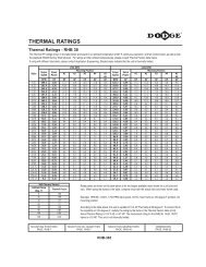
Table 20: Thermal Horsepower Ratings *<br />
High<br />
Speed<br />
Shaft<br />
RPM<br />
1750<br />
1450<br />
Thermal Horsepower Ratings Without Fan † Thermal Horsepower Ratings With Fan ‡<br />
AGMA<br />
Nominal<br />
Ratio 2 3 4 5 6 7 9 10 11 12 3 4 5 6 7 9 10 11 12<br />
2.25 42 54 55 55 44 - - 155 185<br />
2.75 45 59 62 66 72 - - - 211<br />
3.37 - 60 67 74 89 - - - -<br />
4.13 33 46 51 57 61 - 116 138 170<br />
5.06 34 47 53 61 71 143 72 0 0 0 - - 137 174 285 373 299 362 256<br />
6.20 33 46 54 61 76 150 101 43 0 0 - - 131 173 284 381 344 433 393<br />
7.59 32 44 54 61 81 150 121 90 69 39 - - - - 273 385 376 473 500<br />
9.30 29 41 52 58 79 147 132 115 112 118 - - - - 262 - 379 493 543<br />
11.39 - 39 48 55 76 140 137 126 140 158 - - - - - - 368 489 548<br />
13.95 - - 45 51 70 131 132 129 149 181 - - - - - - 349 462 536<br />
17.09 - - 41 46 64 121 126 127 151 189 - - - - - - 326 436 513<br />
20.93 - - 37 42 58 111 115 121 148 184 - - - - - - 300 405 475<br />
25.63 - - - 39 54 100 106 110 137 179 - - - - - - 268 364 445<br />
31.39 - - - - - - 125 114 179 169 - - - - - - - - -<br />
38.44 - - - - - - 111 106 161 157 - - - - - - - - -<br />
47.08 - - - - - - 103 98 147 147 - - - - - - - - -<br />
57.67 - - - - - - - 90 133 135 - - - - - - - - -<br />
70.62 - - - - - - - 81 118 125 - - - - - - - - -<br />
2.25 - 62 68 72 77 - - - 204<br />
2.75 - 64 72 80 95 - - - -<br />
3.37 - - 72 82 105 - - - -<br />
4.13 34 49 56 66 78 - - 136 174<br />
5.06 34 49 57 66 82 159 120 60 30 0 - - 132 - 280 388 352 440 406<br />
6.20 32 47 55 64 83 160 136 101 89 55 - - 126 - 274 389 375 476 484<br />
7.59 32 - 55 63 84 155 144 128 131 135 - - - - 261 - 384 493 545<br />
9.30 - - 52 59 81 150 147 140 154 180 - - - - - - 374 495 556<br />
11.39 - - 47 55 76 142 146 142 166 199 - - - - - - 358 478 547<br />
13.95 - - 44 51 69 131 137 139 165 206 - - - - - - 334 445 522<br />
17.09 - - 41 46 64 121 129 132 160 204 - - - - - - 309 413 493<br />
20.93 - - - 42 58 111 116 123 153 194 - - - - - - - 384 454<br />
25.63 - - - - 53 - 106 111 139 185 - - - - - - - - -<br />
31.39 - - - - - - 124 119 191 183 - - - - - - - -<br />
38.44 - - - - - - 113 111 172 170 - - - - - - - -<br />
47.08 - - - - - - - 103 156 159 - - - - - - - -<br />
57.67 - - - - - - - 95 142 146 - - - - - - - -<br />
70.62 - - - - - - - 85 126 136 - - - - - - -<br />
2.25 - - 77 84 104 - - 169<br />
2.75 - - 77 88 113 - - -<br />
3.37 - - 75 87 115 - - -<br />
4.13 35 50 60 69 88 - - 104 136<br />
5.06 34 - 58 68 89 168 155 123 122 101 - - 101 135 219 316 295 373 371<br />
6.20 - - 55 65 87 165 160 144 153 157 - - 96 130 212 310 306 390 409<br />
7.59 - - 54 63 85 158 160 154 172 203 - - 91 - 202 299 304 392 442<br />
9.30 - - 51 59 81 150 155 154 182 221 - - - - 191 - 292 389 442<br />
1170 11.39 - - 46 55 75 142 150 151 182 226 - - - - - - 278 372 430<br />
13.95 - - - 51 68 130 138 143 172 220 - - - - - - 258 342 406<br />
17.09 - - - - 62 - 129 142 165 212 - - - - - - 254 320 383<br />
20.93 - - - - 56 - 116 123 155 198 - - - - - - 217 296 352<br />
25.63 - - - - 52 - 106 111 139 187 - - - - - - 193 264 328<br />
31.39 - - - - - - - 122 195 192 - - - - - - - - -<br />
38.44 - - - - - - - 113 175 178 - - - - - - - - -<br />
47.08 - - - - - - - 110 - 167 - - - - - - - - -<br />
57.67 - - - - - - - 96 - 154 - - - - - - - - -<br />
* Actual horsepower, without service factor, that reducer will transmit continuously without overheating.<br />
† Values shown are horsepower ratings when thermal HP is less than mechanical HP.<br />
- No values listed if thermal HP is equal to or greater than mechanical HP.<br />
‡ For thermal capacities beyond the range of cooling fans, refer to heat exchanger page G3-40 or consult DODGE.<br />
Sizes 1-3 discounted remaining sotck may be avaialble.<br />
FEATURES/BENEFITS<br />
PAGE G3-3<br />
NOMENCLATURE<br />
PAGE G3-6<br />
G3-68<br />
EASY SELECTION<br />
PAGE G3-7<br />
SELECTION/DIMENSIONS<br />
PAGE G3-23
<strong>ENGINEERING</strong>/<strong>TECHNICAL</strong><br />
MAXUM Concentric Reducer<br />
Table 20: Thermal Horsepower Ratings (cont’d)<br />
High<br />
Speed<br />
Shaft<br />
RPM<br />
870<br />
720<br />
AGMA<br />
Nominal<br />
Ratio<br />
FEATURES/BENEFITS<br />
PAGE G3-3<br />
Thermal Horsepower Ratings Without Fan † Thermal Horsepower Ratings With Fan ‡<br />
2 3 4 5 6 7 9 10 11 12 3 4 5 6 7 9 10 11 12<br />
2.25 - - - 92 121 - - - -<br />
2.75 - - - - 123 - - - -<br />
3.37 - - - - - - - -<br />
4.13 - - 61 71 94 - - 104 -<br />
5.06 - - 57 67 91 169 180 166 189 211 - - 99 - 217 - 330 426 465<br />
6.2 - - 54 64 87 163 176 170 198 231 - - - - - - 323 421 467<br />
7.59 - - 52 61 84 155 169 169 199 248 - - - - - - 310 406 475<br />
9.3 - - - 57 79 146 159 162 197 247 - - - - - - 292 392 456<br />
11.39 - - - - - - 150 154 189 240 - - - - - - 273 367 434<br />
13.95 - - - - - - 134 142 175 227 - - - - - - 250 336 403<br />
17.09 - - - - - - 125 131 165 215 - - - - - - - - 377<br />
20.93 - - - - - - 113 121 153 197 - - - - - - - - -<br />
25.63 - - - - - - - 108 136 189 - - - - - - - - -<br />
31.39 - - - - - - - 122 - 195 - - - - - - - - -<br />
2.25 - - - - - - - - -<br />
2.75 - - - - - - - - -<br />
3.37 - - - - - - - - -<br />
4.13 - - - 70 93 - - - -<br />
5.06 - - - 67 90 167 186 177 209 246 - - - - - - 334 436 488<br />
6.2 - - - 63 90 160 180 176 210 251 - - - - - - 322 424 477<br />
7.59 - - - 60 - - 170 170 206 259 - - - - - - 306 405 476<br />
9.3 - - - - - - 158 160 199 252 - - - - - - 284 386 452<br />
11.39 - - - - - - 148 150 189 241 - - - - - - - - 428<br />
13.95 - - - - - - 131 139 180 226 - - - - - - - - -<br />
17.09 - - - - - - 122 129 163 212 - - - - - - - - -<br />
20.93 - - - - - - - 118 150 194 - - - - - - - - -<br />
25.63 - - - - - - 105 133 180 - - - - - - - - -<br />
2.25 - - - - - - - - - - -<br />
2.75 - - - - - - - - - - -<br />
3.37 - - - - - - - - - - -<br />
4.13 - - - - - - - - - - -<br />
5.06 - - - - - 161 - 183 217 264 - - - - - - - - -<br />
6.2 - - - - - - - 176 214 262 - - - - - - - - -<br />
580 7.59 - - - - - - - 167 204 263 - - - - - - - - -<br />
9.3 - - - - - - - 156 196 251 - - - - - - - - -<br />
11.39 - - - - - - - 145 185 238 - - - - - - - - -<br />
13.95 - - - - - - - 134 170 221 - - - - - - - - -<br />
17.09 - - - - - - - 124 158 206 - - - - - - - - -<br />
20.93 - - - - - - - 113 145 187 - - - - - - - - -<br />
25.63 - - - - - - - 101 128 174 - - - - - - - - -<br />
* Actual horsepower, without service factor, that reducer will transmit continuously without overheating.<br />
† Values shown are horsepower ratings when thermal HP is less than mechanical HP.<br />
- No values listed if thermal HP is equal to or greater than mechanical HP.<br />
‡ For thermal capacities beyond the range of cooling fans, refer to heat exchanger page G3-40 or consult DODGE.<br />
Sizes 1-3 discounted remaining sotck may be avaialble.<br />
NOMENCLATURE<br />
PAGE G3-6<br />
G3-69<br />
EASY SELECTION<br />
PAGE G3-7<br />
SELECTION/DIMENSIONS<br />
PAGE G3-23<br />
TIGEAR-2 MAXUM Concentric Reducer<br />
TORQUE-ARM<br />
TORQUE-ARM II<br />
Gearing Reference Guide
Gearing Reference Guide<br />
TORQUE-ARM II<br />
TORQUE-ARM<br />
MAXUM Concentric Reducer<br />
TIGEAR-2<br />
<strong>ENGINEERING</strong>/<strong>TECHNICAL</strong><br />
MAXUM Concentric Reducer<br />
FEATURES/BENEFITS<br />
PAGE G3-3<br />
Useable Shaft<br />
"N" or "NA"<br />
Distance<br />
"D"<br />
Center Line Of<br />
Overhung Load<br />
NOMENCLATURE<br />
PAGE G3-6<br />
G3-70<br />
Seal Carrier Face<br />
Table 21: Load Location Factors for High Speed Shafts<br />
Distance<br />
In<br />
Inches<br />
1<br />
DCR1/<br />
TCR1<br />
2<br />
DCR2/<br />
TCR2<br />
3<br />
DCR3/<br />
TCR3<br />
4<br />
DCR4<br />
TCR4<br />
MAXUM Reducer Size<br />
5<br />
DCR5 TCR5 DCR6<br />
6<br />
TCR6 DCR7<br />
7<br />
TCR7<br />
1.00 0.99 0.99 0.96 0.96 0.93 0.96 0.93 0.95 0.92 0.92<br />
1.25 1.07 1.07 0.99 0.99 0.95 1.00 0.95 0.98 0.94 0.95<br />
1.50 1.17 1.17 1.06 1.06 0.97 1.08 0.98 1.04 0.95 0.97<br />
1.75 1.27 1.27 1.14 1.14 1.00 1.16 1.00 1.12 0.97 0.99<br />
2.00 1.37 1.37 1.23 1.23 1.07 1.24 1.07 1.20 0.99 1.03<br />
2.25 1.47 1.47 1.31 1.31 1.13 1.31 1.13 1.28 1.01 1.09<br />
2.50 1.57 1.57 1.40 1.40 1.20 1.39 1.20 1.35 1.06 1.14<br />
2.75 1.67 1.67 1.49 1.49 1.27 1.47 1.27 1.43 1.12 1.20<br />
3.00 1.77 1.77 1.57 1.57 1.34 1.55 1.34 1.51 1.18 1.25<br />
3.50 1.74 1.74 1.48 1.71 1.48 1.66 1.29 1.36<br />
4.00 1.62 1.62 1.40 1.47<br />
4.50 1.75 1.75 1.51<br />
5.00 1.63<br />
5.50 1.74<br />
Distance<br />
9 10 11 12<br />
In<br />
Inches<br />
DCR9 TCR9 DCR10 TCR10 DCR11 TCR11 DCR12 TCR12<br />
1.00 0.91 0.91 0.89 0.87 0.87 0.88 0.87 0.90<br />
1.25 0.93 0.93 0.90 0.89 0.88 0.90 0.88 0.91<br />
1.50 0.94 0.95 0.92 0.91 0.89 0.92 0.89 0.93<br />
1.75 0.95 0.97 0.93 0.93 0.91 0.93 0.90 0.95<br />
2.00 0.97 0.99 0.94 0.94 0.92 0.95 0.92 0.97<br />
2.25 0.98 1.03 0.96 0.96 0.93 0.97 0.93 0.99<br />
2.50 1.00 1.07 0.97 0.98 0.94 0.99 0.94 1.02<br />
2.75 1.03 1.12 0.98 1.00 0.95 1.01 0.95 1.07<br />
3.00 1.08 1.17 1.00 1.04 0.96 1.05 0.96 1.11<br />
3.50 1.17 1.26 1.07 1.12 0.99 1.14 0.99 1.20<br />
4.00 1.26 1.36 1.16 1.21 1.04 1.22 1.04 1.29<br />
4.50 1.35 1.45 1.25 1.29 1.11 1.31 1.11 1.38<br />
5.00 1.45 1.34 1.38 1.18 1.39 1.18 1.47<br />
5.50 1.54 1.43 1.25 1.25<br />
6.00 1.63 1.52 1.32 1.32<br />
6.50 1.72 1.60 1.39 1.39<br />
Sizes 1-3 discounted remaining sotck may be avaialble.<br />
EASY SELECTION<br />
PAGE G3-7<br />
SELECTION/DIMENSIONS<br />
PAGE G3-23
<strong>ENGINEERING</strong>/<strong>TECHNICAL</strong><br />
MAXUM Concentric Reducer<br />
Seal Carrier Face<br />
FEATURES/BENEFITS<br />
PAGE G3-3<br />
Useable Shaft<br />
"N" or "NA"<br />
Distance<br />
"D"<br />
Center Line Of<br />
Overhung Load<br />
NOMENCLATURE<br />
PAGE G3-6<br />
G3-71<br />
OHL = 126,000 x hp x Fc x Lf<br />
PD x rpm<br />
Where: OHL = Overhung Load<br />
hp = Horsepower<br />
Fc = Load Connection Factor<br />
(See Table 13, page G3-59)<br />
Lf = Load Location Factor<br />
(See Table 21for High Speed Shafts)<br />
(See Table 22for Low Speed Shafts)<br />
PD = Pitch Diameter of the Item mounted on the Shaft<br />
rpm = Speed of Shaft with Overhung Load on it in<br />
Revolutions Per Minute<br />
(Interpolate for shaft speeds not listed)<br />
Table 22: Load Location Factors For Low Speed Shafts<br />
Distance MAXUM Reducer Size<br />
In<br />
Inches<br />
1 2 3 4 5 6 7 9 10 11 12<br />
1.00 0.93 0.89 0.80 0.83 0.85 0.79 0.79 0.76 0.73 0.72 0.70<br />
1.25 0.98 0.92 0.84 0.86 0.88 0.82 0.81 0.78 0.74 0.74 0.72<br />
1.50 1.04 0.96 0.87 0.88 0.90 0.84 0.83 0.79 0.76 0.75 0.73<br />
1.75 1.12 1.00 0.90 0.91 0.93 0.86 0.85 0.81 0.77 0.77 0.74<br />
2.00 1.20 1.07 0.93 0.94 0.95 0.88 0.87 0.83 0.79 0.78 0.76<br />
2.25 1.28 1.13 0.97 0.97 0.98 0.90 0.89 0.84 0.80 0.80 0.77<br />
2.50 1.36 1.20 1.00 1.00 1.01 0.93 0.91 0.86 0.82 0.81 0.79<br />
2.75 1.44 1.27 1.05 1.05 1.05 0.95 0.93 0.87 0.83 0.82 0.80<br />
3.00 1.52 1.34 1.11 1.10 1.10 0.97 0.95 0.89 0.85 0.84 0.81<br />
3.50 1.69 1.48 1.22 1.21 1.19 1.03 0.99 0.92 0.88 0.87 0.84<br />
4.00 1.62 1.33 1.32 1.28 1.11 1.06 0.95 0.91 0.90 0.87<br />
4.50 1.75 1.44 1.42 1.37 1.20 1.14 0.99 0.94 0.92 0.90<br />
5.00 1.55 1.53 1.46 1.28 1.22 1.03 0.97 0.95 0.93<br />
5.50 1.66 1.64 1.55 1.37 1.30 1.09 1.00 0.98 0.95<br />
6.00 1.74 1.64 1.45 1.38 1.14 1.06 1.02 0.98<br />
6.50 1.74 1.54 1.45 1.20 1.11 1.07 1.02<br />
7.00 1.83 1.62 1.53 1.25 1.17 1.12 1.07<br />
7.50 1.71 1.61 1.31 1.23 1.17 1.12<br />
8.00 1.69 1.36 1.28 1.22 1.16<br />
8.50 1.42 1.34 1.27 1.21<br />
9.00 1.48 1.39 1.32 1.26<br />
9.50 1.53 1.45 1.37 1.31<br />
10.00 1.59 1.50 1.42 1.36<br />
10.50 1.64 1.56 1.47 1.41<br />
11.00 1.70 1.61 1.52 1.46<br />
11.50 1.57 1.51<br />
12.00 1.56<br />
Sizes 1-3 discounted remaining sotck may be avaialble.<br />
EASY SELECTION<br />
PAGE G3-7<br />
SELECTION/DIMENSIONS<br />
PAGE G3-23<br />
TIGEAR-2 MAXUM Concentric Reducer<br />
TORQUE-ARM<br />
TORQUE-ARM II<br />
Gearing Reference Guide
Gearing Reference Guide<br />
TORQUE-ARM II<br />
TORQUE-ARM<br />
MAXUM Concentric Reducer<br />
TIGEAR-2<br />
<strong>ENGINEERING</strong>/<strong>TECHNICAL</strong><br />
MAXUM Concentric Reducer<br />
Table 23: High Speed Shaft Overhung Loads<br />
High<br />
High Speed Shaft Overhung Load (pounds)<br />
AGMA Approx.<br />
Speed Unit<br />
for MAXUM Reducer Size.<br />
Nominal Low Speed<br />
Shaft<br />
Red.<br />
Ratio Shaft RPM<br />
1 2 3 4 5 6 7 9 10 11 12<br />
RPM<br />
5.06 286.6<br />
470 0 570 270 1080 960 1400 30 1750 2000 600<br />
6.2 233.9 470 0 590 420 1080 1000 1400 30 1750 2000 640<br />
7.59 191 470 140 600 660 1080 1250 1400 100 1750 2000 1930<br />
9.3 155.9 470 200 600 700 1080 1250 1400 400 1750 2000 2000<br />
11.39 127.3 470 250 600 810 1080 1250 1400 550 1750 2000 2000<br />
13.95 103.9 470 290 580 770 1080 1250 1400 1750 1750 1900 2000<br />
17.09 84.8 470 310 560 800 1080 1190 1400 1750 1750 1590 2000<br />
20.93 69.3 470 330 590 850 1080 1040 1400 1750 1750 1750 2000<br />
1450<br />
25.63<br />
31.39<br />
56.6<br />
46.2<br />
470<br />
180<br />
100<br />
70<br />
610<br />
20<br />
0<br />
150<br />
1000<br />
0<br />
1250<br />
80<br />
670<br />
280<br />
1500<br />
1000<br />
1750<br />
1200<br />
2000<br />
1200<br />
2000<br />
0<br />
38.44 37.7 180 180 150 310 190 410 670 1180 1200 1200 1200<br />
47.08 30.8 180 260 220 420 370 600 900 1180 1200 1200 1200<br />
57.67 25.1 180 270 280 500 490 760 900 1180 1200 1200 1200<br />
70.62 20.5 180 270 310 540 580 800 900 1180 1200 1200 1200<br />
86.5 16.8 100 140 110 270 160 280 600 800 900 1080 1000<br />
105.9 13.7 100 140 180 270 290 470 600 800 900 1080 1180<br />
129.7 11.2 100 140 180 270 290 470 600 800 900 1080 1180<br />
158.9 9.1 100 140 180 270 290 470 250 270 0 400 1180<br />
194.6 7.5 100 140 180 270 290 470 420 550 520 900 1180<br />
5.06 231.2<br />
470 0 610 90 1080 1020 1400 30 1750 2000 640<br />
6.2 188.7 470 0 630 250 1080 1070 1400 30 1750 2000 690<br />
7.59 154.2 470 200 640 530 1080 1250 1400 30 1750 2000 2000<br />
9.3 125.8 470 270 640 590 1080 1250 1400 30 1750 2000 2000<br />
11.39 102.7 470 320 630 870 1080 1250 1400 200 1750 2000 2000<br />
13.95 83.9 470 360 620 900 1080 1250 1400 1750 1750 2000 2000<br />
17.09 68.5 470 390 660 900 1080 1250 1400 1750 1750 2000 2000<br />
20.93 55.9 470 420 690 900 1080 1110 1400 1750 1750 2000 2000<br />
25.63 45.6 470 80 710 0 950 1250 650 1500 1750 2000 2000<br />
1170 31.39 37.3<br />
180 110 60 210 0 90 300 1180 1200 1200 420<br />
38.44 30.4 180 220 180 360 260 510 820 1180 1200 1200 1200<br />
47.08 24.9 180 270 250 480 440 690 900 1180 1200 1200 1200<br />
57.67 20.3 180 270 310 540 550 800 900 1180 1200 1200 1200<br />
70.62 16.6 180 270 340 540 600 800 900 1180 1200 1200 1200<br />
86.5 13.5 100 140 180 270 260 420 600 800 900 1080 1000<br />
105.9 11 100 140 180 270 290 470 600 800 900 1080 1180<br />
129.7 9 100 140 180 270 290 470 600 800 900 1080 1180<br />
158.9 7.4 100 140 180 270 290 470 250 270 0 370 1180<br />
194.6 6 100 140 180 270 290 470 420 520 500 850 1180<br />
5.06 171.9<br />
470 0 660 80 1080 1110 1400 50 1200 2000 700<br />
6.2 140.3 470 30 680 20 1080 1170 1400 50 1750 2000 750<br />
7.59 114.6 470 310 700 320 1080 1250 1400 50 1750 2000 2000<br />
9.3 93.5 470 380 700 410 1080 1250 1400 50 1750 2000 2000<br />
11.39 76.4 470 430 710 900 1080 1250 1400 50 1750 2000 2000<br />
13.95 62.4 470 480 770 900 1080 1250 1400 1750 1750 2000 2000<br />
17.09 50.9 470 510 800 900 1080 1250 1400 1750 1750 2000 2000<br />
20.93 41.6 470 540 800 900 1080 1250 1400 1750 1750 2000 2000<br />
25.63 33.9 470 60 800 0 900 1250 650 1400 1750 2000 2000<br />
870 31.39 27.7<br />
180 169 120 300 80 280 490 1180 1200 1200 1070<br />
38.44 22.6 180 270 230 450 370 640 900 1180 1200 1200 1200<br />
47.08 18.5 180 270 300 540 540 800 900 1180 1200 1200 1200<br />
57.67 15.1 180 270 350 540 600 800 900 1180 1200 1200 1200<br />
70.62 12.3 180 270 370 540 600 800 900 1180 1200 1200 1200<br />
86.5 10.1 100 140 180 270 290 470 600 800 900 1080 900<br />
105.9 8.2 100 140 180 270 290 470 600 800 900 1080 1180<br />
129.7 6.7 100 140 180 270 290 470 600 800 900 1080 1180<br />
158.9 5.5 100 140 180 270 290 470 250 250 0 350 1180<br />
194.6 4.5 100 140 180 270 290 470 420 500 470 800 1180<br />
† Capacities listed are for pure radial loads on a reducer. If overhung load exceeds the value shown or if overhung load is applied at the same time as thrust loads,<br />
consult DODGE Application Engineering.<br />
Sizes 1-3 discounted remaining sotck may be avaialble.<br />
FEATURES/BENEFITS<br />
PAGE G3-3<br />
DOUBLE<br />
TRIPLE<br />
DOUBLE<br />
TRIPLE<br />
DOUBLE<br />
TRIPLE<br />
NOMENCLATURE<br />
PAGE G3-6<br />
G3-72<br />
EASY SELECTION<br />
PAGE G3-7<br />
SELECTION/DIMENSIONS<br />
PAGE G3-23
<strong>ENGINEERING</strong>/<strong>TECHNICAL</strong><br />
MAXUM Concentric Reducer<br />
Table 23: High Speed Shaft Overhung Loads (cont’d)<br />
High<br />
High Speed Shaft Overhung Load (pounds) †<br />
AGMA Approx.<br />
Speed Unit<br />
for MAXUM Reducer Size<br />
Nominal Low Speed<br />
Shaft<br />
Red.<br />
Ratio Shaft RPM<br />
1 2 3 4 5 6 7 9 10 11 12<br />
RPM<br />
5.06 142.3<br />
470 0 700 170 1080 1180 1400 50 500 1650 740<br />
6.2 116.1 470 100 730 20 1080 1240 1400 50 1500 2000 860<br />
7.59 94.9 470 380 740 180 1080 1250 1400 50 1750 2000 2000<br />
9.3 77.4 470 460 750 370 1080 1250 1400 50 1750 2000 2000<br />
11.39 63.2 470 510 800 900 1080 1250 1400 50 1750 2000 2000<br />
13.95 51.6 470 560 800 900 1080 1250 1400 1750 1750 2000 2000<br />
17.09 42.1 470 590 800 900 1080 1250 1400 1750 1750 2000 2000<br />
20.93 34.4 470 620 800 900 1080 1250 1400 1750 1750 2000 2000<br />
720<br />
25.63<br />
31.39<br />
28.1<br />
22.9<br />
470<br />
180<br />
50<br />
210<br />
800<br />
150<br />
0<br />
360<br />
850<br />
180<br />
1250<br />
390<br />
600<br />
670<br />
1300<br />
1180<br />
1750<br />
1200<br />
2000<br />
1200<br />
2000<br />
1200<br />
38.44 18.7 180 270 260 500 440 740 900 1180 1200 1200 1200<br />
47.08 15.3 180 270 330 540 600 800 900 1180 1200 1200 1200<br />
57.67 12.5 180 270 370 540 600 800 900 1180 1200 1200 1200<br />
70.62 10.2 180 270 370 540 600 800 900 1180 1200 1200 1200<br />
86.5 8.3 100 140 180 270 290 470 600 800 900 1080 800<br />
105.9 6.8 100 140 180 270 290 470 600 800 900 1080 1180<br />
129.7 5.6 100 140 180 270 290 470 600 800 900 1080 1180<br />
158.9 4.5 100 140 180 270 290 470 250 220 0 320 1180<br />
194.6 3.7 100 140 180 270 290 470 420 450 450 750 1180<br />
5.06 114.6<br />
470 70 750 270 1080 1250 1400 50 50 1000 800<br />
6.2 93.5 470 190 770 20 1080 1250 1400 50 650 1700 1600<br />
7.59 76.4 470 470 790 100 1080 1250 1400 50 1600 2000 2000<br />
9.3 62.4 470 550 800 360 1080 1250 1400 50 1750 2000 2000<br />
11.39 50.9 470 610 800 900 1080 1250 1400 50 1750 2000 2000<br />
13.95 41.6 470 620 800 900 1080 1250 1400 1750 1750 2000 2000<br />
17.09 33.9 470 620 800 900 1080 1250 1400 1750 1750 2000 2000<br />
20.93 27.7 470 620 800 900 1080 1250 1400 1750 1750 2000 2000<br />
25.63 22.6 470 0 800 0 750 1250 600 1200 1750 2000 2000<br />
580 31.39 18.5<br />
180 260 200 430 300 530 880 1180 1200 1200 1200<br />
38.44 15.1 180 270 300 540 530 800 900 1180 1200 1200 1200<br />
47.08 12.3 180 270 370 540 600 800 900 1180 1200 1200 1200<br />
57.67 10.1 180 270 370 540 600 800 900 1180 1200 1200 1200<br />
70.62 8.2 180 270 370 540 600 800 900 1180 1200 1200 1200<br />
86.5 6.7 100 140 180 270 290 470 600 800 900 1080 700<br />
105.9 5.5 100 140 180 270 290 470 600 800 900 1080 1180<br />
129.7 4.5 100 140 180 270 290 470 600 800 900 1080 1180<br />
158.9 3.7 100 140 180 270 290 470 200 200 0 300 1180<br />
194.6 3 100 140 180 270 290 470 400 400 400 700 1180<br />
† Capacities listed are for pure radial loads on a reducer. If overhung load exceeds the value shown or if overhung load is applied at the same time<br />
as thrust loads, consult DODGE Application Engineering.<br />
Sizes 1-3 discounted remaining sotck may be avaialble.<br />
FEATURES/BENEFITS<br />
PAGE G3-3<br />
DOUBLE<br />
TRIPLE<br />
DOUBLE<br />
TRIPLE<br />
NOMENCLATURE<br />
PAGE G3-6<br />
G3-73<br />
EASY SELECTION<br />
PAGE G3-7<br />
SELECTION/DIMENSIONS<br />
PAGE G3-23<br />
TIGEAR-2 MAXUM Concentric Reducer<br />
TORQUE-ARM<br />
TORQUE-ARM II<br />
Gearing Reference Guide
Gearing Reference Guide<br />
TORQUE-ARM II<br />
TORQUE-ARM<br />
MAXUM Concentric Reducer<br />
TIGEAR-2<br />
<strong>ENGINEERING</strong>/<strong>TECHNICAL</strong><br />
MAXUM Concentric Reducer<br />
Table 24: Low Speed Overhung Loads<br />
Approx.<br />
Overhung Load Capacity<br />
Unit<br />
Low Speed MAXUM Reducer Size (multiply value shown by 1000) ♣<br />
Red.<br />
Shaft RPM 1 2 3 4 5 6 7 9 10 11 12<br />
777.8<br />
1.38 1.94 2.29 2.87 3.69 4.84 • • • • •<br />
636.4 1.43 2.05 2.37 2.96 3.87 5.07 • • • • •<br />
519.3 1.54 2.16 2.52 3.12 4.08 5.33 • • • • •<br />
423.7 1.41 2.1 2.64 3.17 3.98 5.39 • • • • •<br />
345.8 1.47 2.19 2.78 3.32 4.18 5.65 7.05 10.3 10.3 12.2 10.4<br />
282.3 1.54 2.28 2.94 3.51 4.39 5.95 7.56 10.7 10.9 12.8 10.9<br />
230.6 1.62 2.32 3.13 3.70 4.66 6.29 7.48 11.2 11.5 13.4 11.3<br />
188.2 1.74 2.53 3.31 3.91 4.95 6.61 8.27 11.9 12.1 14.1 12.0<br />
153.6 1.90 2.74 3.48 4.14 5.27 6.98 8.97 12.5 12.7 14.9 12.7<br />
125.4 2.07 2.98 3.70 4.37 5.71 7.43 9.88 13.3 13.5 15.7 13.8<br />
102.4 2.26 3.24 3.92 4.63 6.16 7.78 10.9 14.1 14.2 16.6 14.9<br />
83.6 2.47 3.51 4.19 4.98 6.62 8.25 11.8 14.9 15.1 17.7 16.0<br />
68.3 2.70 3.79 4.47 5.46 7.13 8.66 13.1 15.8 16.0 19.4 17.5<br />
55.8<br />
2.91 4.08 4.85 5.86 8.03 9.64 14.6 16.9 17.5 21.7 19.6<br />
45.5 3.16 4.40 5.22 6.31 8.51 10.2 15.4 18.2 18.5 22.6 21.0<br />
37.2 3.40 4.74 5.48 6.80 8.85 10.5 16.6 19.7 19.9 24.4 22.8<br />
30.4 3.55 4.78 5.48 6.98 8.88 10.5 17.8 20.0 21.8 26.5 24.8<br />
24.8 3.58 4.80 5.48 6.98 8.90 10.5 17.8 20.0 23.7 28.6 27.1<br />
20.2 3.58 4.80 5.48 6.98 8.95 10.6 17.9 20.0 24.6 29.5 29.4<br />
16.5 3.60 4.83 5.48 6.98 8.98 10.6 17.9 20.0 24.6 29.5 29.4<br />
13.5 3.60 4.85 5.48 6.98 9.00 10.6 17.9 20.0 24.6 29.5 29.4<br />
11.0 3.63 4.85 5.48 6.98 9.03 10.6 18.0 20.0 24.6 29.5 29.4<br />
9.0 3.63 4.85 5.48 6.98 9.05 10.7 18.0 20.0 24.6 29.5 29.4<br />
DOUBLE<br />
TRIPLE<br />
* Interpolate for intermediate values.<br />
♣ Capacities are for pure radial loads.<br />
If overhung loads are applied at the same time as thrust loads, consult DODGE Application Engineering.<br />
• Consult DODGE.<br />
Table 25: Actual Ratios<br />
AGMA<br />
Nominal<br />
Ratio<br />
Approx.<br />
Low Speed<br />
Shaft RPM<br />
Unit<br />
Red.<br />
1 2 3 4<br />
Actual Ratio of Reduction<br />
MAXUM Reducer Size<br />
5 6 7 9 10 11 12<br />
2.25 777.8<br />
2.253 2.259 2.263 2.225 2.263 2.273<br />
2.75 636.4 2.801 2.800 2.760 2.679 2.750 2.770<br />
3.37 519.3 3.406 3.373 3.364 3.320 3.338 3.392<br />
4.13 423.7 4.091 4.108 4.167 4.125 4.114 4.133<br />
5.06 345.8 5.087 5.091 5.081 4.966 5.000 5.037 5.065 5.103 4.958 5.104 5.089<br />
6.20 282.3 6.184 6.133 6.194 6.154 6.069 6.167 6.115 6.154 6.109 6.134 6.220<br />
7.59 230.6 7.639 7.484 7.813 7.586 7.520 7.680 7.527 7.478 7.589 7.552 7.464<br />
9.30 188.2 9.282 9.333 9.524 9.280 9.273 9.273 9.217 9.200 9.385 9.077 9.325<br />
11.39 153.6 11.28 11.30 11.33 11.45 11.37 11.37 11.21 11.20 11.33 11.28 11.31<br />
13.95 125.4 13.79 14.00 14.09 13.89 14.00 14.25 13.91 13.88 13.93 13.89 13.98<br />
17.09 102.4 16.87 17.18 17.13 17.00 17.14 16.86 17.47 17.14 16.73 16.90 16.90<br />
20.93 83.6 20.83 21.14 21.11 20.57 20.67 20.67 21.06 21.00 20.92 20.83 20.60<br />
25.63 68.3 25.64 25.67 25.32 26.18 25.20 24.67 25.68 25.60 25.89 25.32 25.59<br />
31.39 55.8<br />
30.90 30.96 31.28 31.50 31.38 32.00 30.50 30.68 31.61 31.29 31.21<br />
38.44 45.5 37.77 38.35 38.88 38.21 38.64 40.11 37.83 38.03 38.86 38.51 38.60<br />
47.08 37.2 46.20 47.05 47.28 46.75 47.31 47.45 47.53 46.96 46.68 46.85 46.63<br />
57.67 30.4 57.05 57.91 58.27 56.57 57.04 58.17 57.29 57.52 58.36 57.77 56.85<br />
70.62 24.8 70.22 70.30 69.88 72.00 69.55 69.43 69.86 70.12 72.21 70.21 70.63<br />
86.50 20.2 85.73 85.91 85.52 86.86 86.81 86.21 86.27 86.94 85.07 86.60 86.36<br />
105.9 16.5 104.8 106.4 106.3 105.4 106.9 108.1 104 106.5 106.4 106.8 106.8<br />
129.7 13.5 128.2 130.5 129.3 128.9 130.9 127.8 126.8 129.8 131.6 129.8 129<br />
158.9 11.0 158.3 160.7 159.3 156 157.8 156.7 158.9 157.5 159.8 159.1 157.3<br />
194.6 9.0 194.8 195.1 191.1 198.5 192.4 187.1 193.8 192 197.7 193.4 195.4<br />
† Based on 1750 high speed shaft RPM.<br />
Sizes 1-3 discounted remaining sotck may be avaialble.<br />
FEATURES/BENEFITS<br />
PAGE G3-3<br />
DOUBLE<br />
TRIPLE<br />
NOMENCLATURE<br />
PAGE G3-6<br />
G3-74<br />
EASY SELECTION<br />
PAGE G3-7<br />
SELECTION/DIMENSIONS<br />
PAGE G3-23
<strong>ENGINEERING</strong>/<strong>TECHNICAL</strong><br />
MAXUM Concentric Reducer<br />
Table 26: WR2 Values<br />
AGMA<br />
Nominal<br />
Ratio<br />
Approx. †<br />
Low Speed<br />
Shaft RPM<br />
Unit<br />
Red.<br />
1 2 3<br />
WR2 (lb. - In2) at high Speed Shaft ★<br />
MAXUM Reducer Size<br />
4 5 6 7 9 10 11 12<br />
2.25 777.8<br />
10.22 17.02 42.06 77.41 125.4 253.9<br />
2.75 636.4 7.699 12.61 32 59.02 94.8 189.3<br />
3.37 519.3 6.11 9.869 24.59 43.48 73.97 141.5<br />
4.13 423.7 7.932 12.86 31.9 57.81 93.81 184.3<br />
5.06 345.8 6.217 9.901 25.17 45.49 73.42 142.4 309.3 768.4 1469 2529 4140<br />
6.2 282.3 5.107 8.004 19.99 34.67 59.45 110.3 259.9 611.2 1127 2008 3201<br />
7.59 230.6 4.24 6.408 15.55 26.33 46.29 82.57 205.8 487.2 868.0 1559 2559<br />
9.3 188.2 3.633 5.179 12.7 21.03 37.06 66.14 164.5 387.7 683.6 1272 1959<br />
11.39 153.6 3.158 4.344 10.73 16.09 29.44 50.6 133.1 309.6 558.5 1003 1564<br />
13.95 125.4 2.807 3.528 8.316 13 24.09 39.11 106.4 258.8 455.0 813.6 1234<br />
17.09 102.4 2.35 2.898 6.616 10.45 19.65 32.35 85.34 209.7 373.0 655.3 986.5<br />
20.93 83.6 2.017 2.466 5.406 8.541 17.24 25.92 72.74 173.7 298.5 525.0 784.6<br />
25.63 68.3 1.765 2.147 4.559 6.967 15.01 21.9 61.73 148.5 244.9 428.2 622.0<br />
31.39 55.8<br />
2.196 3.322 5.609 8.648 11.88 19.57 48.58 106.9 185.8 337.9 493.5<br />
38.44 45.5 2.140 3.225 5.370 8.272 11.25 18.20 45.38 99.01 172.3 311.5 449.4<br />
47.08 37.2 2.099 3.158 5.208 7.972 10.73 17.42 42.93 93.41 163.0 293.2 419.0<br />
57.67 30.4 2.068 3.110 5.077 7.746 10.38 16.69 41.39 89.04 154.7 278.4 394.2<br />
70.62 24.8 2.046 3.073 4.985 7.549 10.11 16.18 40.11 86.03 148.5 267.6 374.5<br />
86.50 20.2 1.170 1.579 2.303 3.333 4.771 6.594 27.36 52.16 84.71 145.5 144.1<br />
105.9 16.5 1.163 1.566 2.271 3.284 4.689 6.406 26.89 50.89 82.20 141.2 138.4<br />
129.7 13.5 1.158 1.558 2.249 3.244 4.621 6.298 26.50 50.01 80.33 138.0 134.4<br />
158.9 11.0 1.154 1.552 2.232 3.214 4.576 6.197 22.60 40.82 62.58 107.0 131.2<br />
194.6 9.0 1.151 1.547 2.220 3.189 4.541 6.127 22.43 40.42 61.76 105.5 128.6<br />
★ For WR 2 at low speed shaft, multiply the WR 2 value listed by (actual ratio) 2 . See Table 25 for actual ratios.<br />
† Based on 1750 high speed shaft RPM.<br />
Sizes 1-3 discounted remaining sotck may be avaialble.<br />
FEATURES/BENEFITS<br />
PAGE G3-3<br />
DOUBLE<br />
TRIPLE<br />
NOMENCLATURE<br />
PAGE G3-6<br />
G3-75<br />
EASY SELECTION<br />
PAGE G3-7<br />
SELECTION/DIMENSIONS<br />
PAGE G3-23<br />
TIGEAR-2 MAXUM Concentric Reducer<br />
TORQUE-ARM<br />
TORQUE-ARM II<br />
Gearing Reference Guide
Gearing Reference Guide<br />
TORQUE-ARM II<br />
TORQUE-ARM<br />
MAXUM Concentric Reducer<br />
TIGEAR-2<br />
<strong>ENGINEERING</strong>/<strong>TECHNICAL</strong><br />
MAXUM Concentric Reducer<br />
CAUTION: Unit is shipped without oil. Add<br />
proper amount of re<strong>com</strong>mended lubricant before<br />
operating. Failure to observe these precautions<br />
could result in damage to, or destruction of, the<br />
equipment.<br />
Lubrication is extremely important for satisfactory<br />
operation. The proper oil level as shown in Table 29, page<br />
G3-77, must be maintained at all times. Frequent<br />
inspections with the unit not running and allowing sufficient<br />
time for the oil to cool and the entrapped air to settle out of<br />
the oil should be made by removing the level plug to see<br />
that the level is being maintained. If low, add the proper<br />
type and viscosity of lubricant through one of the upper<br />
openings until it <strong>com</strong>es out of the oil level hole. Replace the<br />
oil level plug securely. Refer to Table 27 and Table 28<br />
below for viscosity re<strong>com</strong>mendations.<br />
After an initial operation of about two weeks, the oil should<br />
be changed. If desired, this oil may be filtered and reused.<br />
Very often, small metal particles will show up in the oil due<br />
to the wearing in process. After the initial break in period,<br />
the lubricant should be drained, magnetic drain plug<br />
cleaned, gear case flushed and refilled every 2500 hours of<br />
operation under average industrial conditions. More<br />
frequent oil changes are re<strong>com</strong>mended when operating<br />
Table 27: Lubrication Re<strong>com</strong>mendations - ISO Grades for<br />
Ambient Temperatures of 50 thru 125 Degrees F *<br />
FEATURES/BENEFITS<br />
PAGE G3-3<br />
NOMENCLATURE<br />
PAGE G3-6<br />
G3-76<br />
continuously or at high temperatures or under conditions of<br />
extreme dirt or dust. Use only re<strong>com</strong>mended lubricants<br />
listed on this page, or equivalent. Special attention should<br />
be given to checking of lubricants when any of the following<br />
conditions exist:<br />
10. High operating temperatures resulting from heavy<br />
intermittent loads causing the temperature of the gear<br />
case to rise rapidly and then cool.<br />
11. Unusual ambient conditions, which may tend to cause<br />
condensation on the inside of the gear case thereby<br />
contaminating the oil.<br />
12. Operating temperatures that would cause oil to<br />
approach 200�F continually.<br />
13. If the reducer is subjected to unusual vapors or moist<br />
atmosphere.<br />
Operating Temperatures<br />
Heating is a natural characteristic of enclosed gearing, and<br />
a maximum gear case temperature approaching 200�F is<br />
not un<strong>com</strong>mon for some units operating in normal ambient<br />
temperatures (80�F). When operating at rated capacity, no<br />
damage will result from this temperature as this was taken<br />
into consideration in the design of the gear case and in the<br />
selection of the lubricants.<br />
Output MAXUM Reducer Size<br />
RPM 1 2 3 4 5 6 7 9 10 11 12<br />
Lubricant Grade Equivalents<br />
230 220 220 220 220 220 220 220 220 220 220 220 ISO AGMA<br />
190 320 320 220 220 220 220 220 220 220 220 220 150 4<br />
155 320 320 320 220 220 220 220 220 220 220 220 220 5<br />
125 320 320 320 320 320 220 220 220 220 220 220 320 6<br />
100 320 320 320 320 320 320 220 220 220 220 220<br />
84 320 320 320 320 320 320 220 220 220 220 220 NOTE: Mobile SHC 630 Series oil is<br />
68 320 320 320 320<br />
56 320 320 320 320<br />
45 320 320 320 320<br />
* NOTES:<br />
1. Use lSO 220 above 230 Output RPM.<br />
320<br />
320<br />
320<br />
320<br />
320<br />
320<br />
320<br />
320<br />
320<br />
220<br />
320<br />
320<br />
220<br />
320<br />
320<br />
220<br />
320<br />
320<br />
220<br />
220<br />
320<br />
re<strong>com</strong>mended for high ambient<br />
temperatures. For a wide<br />
range of ambient temperatures<br />
(-10 F/120 F) use<br />
Mobile SHC 629,<br />
2. Use ISO 320 below 45 Output RPM.<br />
3. Assumes Auxiliary Cooling where Re<strong>com</strong>mended in the Catalog.<br />
Table 28: Lubrication Re<strong>com</strong>mendations ISO Grades For<br />
Ambient Temperatures Of 15 Thru 60 Degrees F*<br />
Output MAXUM Reducer Size<br />
RPM 1 2 3 4 5 6 7 9 10 11 12<br />
230 150 150 150 150 150 150 150 150 150 150 150<br />
190 220 220 150 150 150 150 150 150 150 150 150<br />
155 220 220 220 150 150 150 150 150 150 150 150<br />
125 220 220 220 220 220 150 150 150 150 150 150 * NOTES:<br />
100 220 220 220 220 220 220 150 150 150 150 150 1. Use ISO 150 above 230 Output<br />
84 220 220 220 220 220 220 150 150 150 150 150 RPM.<br />
68 220 220 220 220 220 220 220 150 150 150 150 2. Use ISO 220 below 45 Output RPM.<br />
56 220 220 220 220 220 220 220 220 220 220 150 3. Assumes Auxiliary Cooling where<br />
45 220 220 220 220 220 220 220 220 220 220 220<br />
Re<strong>com</strong>mended in the Catalog.<br />
EASY SELECTION<br />
PAGE G3-7<br />
SELECTION/DIMENSIONS<br />
PAGE G3-23
<strong>ENGINEERING</strong>/<strong>TECHNICAL</strong><br />
MAXUM Concentric Reducer<br />
OIL LEVEL LOCATIONS FOR POSTION A-1<br />
L-A<br />
FEATURES/BENEFITS<br />
PAGE G3-3<br />
D<br />
Use For Oil Levels<br />
MAXUM Sizes 7-9<br />
L= LEVEL PLUG<br />
V<br />
L-A<br />
L-B<br />
NOMENCLATURE<br />
PAGE G3-6<br />
D= DRAIN PLUG<br />
D<br />
G3-77<br />
V<br />
Use For Oil Levels<br />
MAXUM Sizes 1-6<br />
L-A<br />
V= VENT PLUG<br />
L-B<br />
EASY SELECTION<br />
PAGE G3-7<br />
V<br />
D<br />
Use For Oil Levels<br />
MAXUM Sizes 10-12<br />
Table 29: Approximate Oil Capacities And Oil Levels*<br />
VS Output RPM’S For Floor Mounted Position<br />
MAXUM<br />
Size<br />
Output<br />
RPM<br />
Approximate<br />
Oil<br />
Capacity<br />
Level<br />
Position<br />
MAXUM<br />
Size<br />
Output<br />
RPM<br />
Approximate<br />
Oil<br />
Capacity<br />
Level<br />
Position<br />
1<br />
ABOVE 375<br />
BELOW 375<br />
2.8 QUARTS<br />
5.2 QUARTS<br />
L-AL-B 7<br />
ABOVE 175<br />
BELOW 175<br />
8.3 GALLONS<br />
17.6 GALLONS<br />
L-AL-B<br />
2<br />
ABOVE 355<br />
BELOW 355<br />
4.1 QUARTS<br />
7.3 QUARTS<br />
L-AL-B 9<br />
ABOVE 140<br />
BELOW 140<br />
12.6 GALLONS<br />
27.2 GALLONS<br />
L-AL-B<br />
3<br />
ABOVE 300<br />
BELOW 300<br />
6.5 QUARTS<br />
12.0 QUARTS<br />
L-AL-B 10<br />
ABOVE 120<br />
BELOW 120<br />
12.9 GALLONS<br />
29.8 GALLONS<br />
L-AL-B<br />
4<br />
ABOVE 270<br />
BELOW 270<br />
9.0 QUARTS<br />
16.6 QUARTS<br />
L-AL-B 11<br />
ABOVE 110<br />
BELOW 110<br />
16.3 GALLONS<br />
36.9 GALLONS<br />
L-AL-B<br />
5<br />
ABOVE 250<br />
BELOW 250<br />
10.9 QUARTS<br />
21.2 QUARTS<br />
L-AL-B 12<br />
ABOVE 95<br />
BELOW 95<br />
20.0 GALLONS<br />
42.5 GALLONS<br />
L-AL-B<br />
6<br />
ABOVE 215<br />
BELOW 215<br />
15.7 QUARTS<br />
30.7 QUARTS<br />
L-AL-B<br />
* Always fill to the oil plug regardless of the stated quantities. Refer to instruction manual for more information.<br />
The lubrication instructions on pages G3-76 and G3-77 are offered for general guidelines. Refer to the instruction manual shipped with the reducer<br />
for specific lubrication instructions<br />
L-B<br />
SELECTION/DIMENSIONS<br />
PAGE G3-23<br />
TIGEAR-2 MAXUM Concentric Reducer<br />
TORQUE-ARM<br />
TORQUE-ARM II<br />
Gearing Reference Guide
Gearing Reference Guide<br />
TORQUE-ARM II<br />
TORQUE-ARM<br />
MAXUM Concentric Reducer<br />
TIGEAR-2<br />
<strong>ENGINEERING</strong>/<strong>TECHNICAL</strong><br />
MAXUM Concentric Reducer<br />
DODGE MAXUM Concentric Shaft Reducers can be<br />
modified to permit mounting in positions other than the<br />
conventional (A-1) floor mounting. Some of these include<br />
ceiling (A-3) and wall (A-2 and A-4) and various inclined,<br />
vertical and tilted positions. Consult DODGE to determine<br />
what modifications are required for your specific<br />
application.<br />
In order for DODGE to make re<strong>com</strong>mendations on the<br />
required modifications, the following information must be<br />
provided:<br />
FEATURES/BENEFITS<br />
PAGE G3-3<br />
Angle Of Incline<br />
Specify Input or Output Shaft Up<br />
A-3<br />
A-2 Viewed from Output Shaft<br />
NOMENCLATURE<br />
PAGE G3-6<br />
G3-78<br />
Angle Of Tilt<br />
Specify Left or Right Side High<br />
When Viewed from Output Shaft<br />
• Reducer Size.<br />
• Ratio.<br />
• Input and/or output speed.<br />
• Transmitted Horsepower.<br />
• Duty cycle. Continuous or intermittent operation. If<br />
intermittent, running time vs. idle time.<br />
• Mounting position, such as A-2, A-3 or A-4 with shafts<br />
level, or a more <strong>com</strong>plete descri<strong>pt</strong>ion of the mounting<br />
arrangement including the angle of tilt of the housing,<br />
the incline of the shafts and whether the output shaft is<br />
higher or lower than the input shaft.<br />
EASY SELECTION<br />
PAGE G3-7<br />
A-4<br />
SELECTION/DIMENSIONS<br />
PAGE G3-23
<strong>ENGINEERING</strong>/<strong>TECHNICAL</strong><br />
MAXUM Concentric Reducer Vertical And Inclined Application<br />
When the reducer is mounted vertically, the upper bearings<br />
will not receive adequate lubrication from normal means of<br />
splash lubrication. The MAXUM reducer design uses a<br />
center web in the housing to support the inside bearings.<br />
This center web be<strong>com</strong>es a splash baffle when the reducer<br />
is mounted in a vertical position so other alternatives for<br />
lubrication need to be considered.<br />
DRAWING A<br />
In addition to the Nylos Ring, we provide a means to<br />
initially charge and replace the grease reservoir. The seal<br />
carrier of the housing is drilled, and a grease fitting is<br />
provided to maintain a level of lubricant in this cavity.<br />
Lubrication of the upper gearset also needs to be<br />
SPECIAL<br />
SEAL<br />
CARRIER<br />
OIL FILL<br />
LEVEL<br />
FEATURES/BENEFITS<br />
PAGE G3-3<br />
GREASE<br />
FITTING<br />
PLUMBING<br />
HARDWARE<br />
TO RAISE OIL TO<br />
PROPER LEVEL<br />
DRAWING B<br />
GREASE<br />
PATH<br />
GREASE RETAINER<br />
(NYLOS RING)<br />
NOMENCLATURE<br />
PAGE G3-6<br />
GREASE RETAINER<br />
(NYLOS RING)<br />
G3-79<br />
The MAXUM solution to this problem is to use a Nylos Ring<br />
- a thin dish or cup mounted between the shaft shoulders<br />
and the Timken cone (see Drawing A). The purpose of this<br />
cup is to hold a reservoir of grease to lubricate the upper<br />
bearings. If the low speed shaft is up, we provide this<br />
modification for both the low speed pinion bearing and the<br />
countershaft bearing.<br />
SHAFT<br />
SEAL<br />
considered, and this is provided for by increasing the<br />
lubricant level to make contact with the upper gearset. We<br />
provide this information for each application, by a drawing<br />
similar to Drawing B below.<br />
ANGLE<br />
EASY SELECTION<br />
PAGE G3-7<br />
SPECIAL<br />
SEAL<br />
CARRIER<br />
BEARING CUP<br />
AND CONE<br />
PROPER OIL LEVEL WILL VARY<br />
WITH REDUCER SIZE, RATIO,<br />
INPUT SPEED, AND ANGLE OF<br />
INCLINE. ALWAYS CONSULT<br />
DODGE FOR PROPER OIL LEVEL.<br />
SELECTION/DIMENSIONS<br />
PAGE G3-23<br />
TIGEAR-2 MAXUM Concentric Reducer<br />
TORQUE-ARM<br />
TORQUE-ARM II<br />
Gearing Reference Guide
Gearing Reference Guide<br />
TORQUE-ARM II<br />
TORQUE-ARM<br />
MAXUM Concentric Reducer<br />
TIGEAR-2<br />
<strong>ENGINEERING</strong>/<strong>TECHNICAL</strong><br />
MAXUM Concentric Reducer Vertical And Inclined Application<br />
We are frequently asked at what angle of incline should the<br />
vertical modification be considered. On the list price<br />
modification page, we state “exceeding 10� of incline”. This<br />
is conservative and would provide the lubrication required<br />
at very slow output speeds where there would be minimum<br />
splash generated. If the MAXUM reducer is operating at<br />
moderate to high speed, this minimum guideline may be<br />
increased. See Drawing C.<br />
ANGLE<br />
PLUMBING<br />
HARDWARE<br />
TO RAISE OIL TO<br />
PROPER LEVEL<br />
DRAWING C<br />
DRAWING D<br />
OIL FILL LEVEL<br />
PLUMBING HARDWARE TO<br />
RAISE OIL TO PROPER LEVEL<br />
FEATURES/BENEFITS<br />
PAGE G3-3<br />
NOMENCLATURE<br />
PAGE G3-6<br />
OIL FILL<br />
LEVEL<br />
G3-80<br />
UPPER<br />
BEARINGS<br />
PARTIALLY<br />
SUBMERGED<br />
ANGLE<br />
Another area where special lubrication needs to be<br />
considered is “tilt mounting”. The input and output shafts<br />
are horizontal but the reducer may be mounted in an A-2,<br />
A-3 or A-4 position or at some angle in between. The<br />
solution for this type of mounting is one of using the proper<br />
oil level only (no modification needed). Drawing D<br />
illustrates the use of a standpipe to meed oil level<br />
requirements.<br />
ANGLE<br />
EASY SELECTION<br />
PAGE G3-7<br />
PROPER OIL LEVEL WILL VARY<br />
WITH REDUCER SIZE, RATIO,<br />
INPUT SPEED, AND ANGLE OF<br />
INCLINE. ALWAYS CONSULT<br />
DODGE FOR PROPER OIL LEVEL.<br />
THESE ILLUSTRATIONS REPRESENT<br />
TYPICAL ARRANGEMENTS FOR<br />
TILT MOUNTED REDUCERS.<br />
PROPER OIL LEVEL WILL VARY<br />
WITH REDUCER SIZE, RATIO, INPUT<br />
SPEED, AND ANGLE OF TILT.<br />
ALWAYS CONSULT DODGE FOR<br />
PROPER OIL LEVEL.<br />
PLUMBING HARDWARE TO<br />
RAISE OIL TO PROPER LEVEL<br />
SELECTION/DIMENSIONS<br />
PAGE G3-23
<strong>ENGINEERING</strong>/<strong>TECHNICAL</strong><br />
MAXUM Concentric Reducer<br />
GENERAL GUIDELINES FOR MOUNTING VARIABLE SPEED AC OR DC MOTORS<br />
AMPLITUDE RATIO<br />
DEFINITIONS:<br />
FUNDAMENTAL NATURAL FREQUENCY is the lowest<br />
number of times per minute that the motor and supporting<br />
structure will maintain a periodic oscillation, once<br />
displaced, under the sole influence of its own mass and<br />
stiffness.<br />
RESONANCE is a vibration of large amplitude caused by<br />
the small periodic stimulus of the unbalance force when the<br />
motor speed is the same or nearly the same frequency as<br />
FEATURES/BENEFITS<br />
PAGE G3-3<br />
NOMENCLATURE<br />
PAGE G3-6<br />
G3-81<br />
the fundamental natural frequency of the motor and<br />
support structure.<br />
SOFT MOUNTING - The fundamental natural frequency is<br />
below the motor operating speed.<br />
HARD MOUNTING - The fundamental natural frequency is<br />
above the motor operating speed.<br />
(Continued on page G3-82)<br />
EASY SELECTION<br />
PAGE G3-7<br />
SELECTION/DIMENSIONS<br />
PAGE G3-23<br />
TIGEAR-2 MAXUM Concentric Reducer<br />
TORQUE-ARM<br />
TORQUE-ARM II<br />
Gearing Reference Guide
Gearing Reference Guide<br />
TORQUE-ARM II<br />
TORQUE-ARM<br />
MAXUM Concentric Reducer<br />
TIGEAR-2<br />
<strong>ENGINEERING</strong>/<strong>TECHNICAL</strong><br />
MAXUM Concentric Reducer<br />
GENERAL GUIDELINES FOR MOUNTING VARIABLE SPEED AC OR DC MOTORS<br />
SCOOP MOUNT ACCESSORY<br />
1. This is a soft mounting of the motor.<br />
2. The benefits obtained by using this accessory are low<br />
cost and isolation of the reducer support structure<br />
from the motor vibration.<br />
3. This motor mount was designed for use with a<br />
constant speed motor at 1750 RPM. Use of motors<br />
with lower base speeds increases the chance of<br />
producing resonance.Stiffening techniques within the<br />
scoop structure can increase the fundamental natural<br />
frequency about 20% which is generally enough to<br />
eliminate resonance should it occur.<br />
4. This accessory is NOT re<strong>com</strong>mended for variable<br />
speed DC or AC applications.<br />
5. Customers who prefer to use the scoop mount<br />
accessory to mount variable speed AC or DC motors<br />
must state on the face of the purchase order that they<br />
plan to support scoop and assume full responsibility<br />
for any vibratory or transient load induced by the<br />
motor. For re<strong>com</strong>mended scoop support, contact<br />
Reliance Electric and reference drawing #A31512.<br />
NOTE: For more information on DODGE MAXUM<br />
Concentric Reducer Scoop Mount Reducers,<br />
refer to page G3-41.<br />
TOP MOUNT ACCESSORY<br />
1. This may be a soft or hard mounting of the motor<br />
depending on the size of the motor and the distance<br />
that the adjusting screws are extended.<br />
FEATURES/BENEFITS<br />
PAGE G3-3<br />
NOMENCLATURE<br />
PAGE G3-6<br />
G3-82<br />
2. The benefits obtained by using this accessory are low<br />
cost, minimum floor space used for the motor/reducer<br />
assembly, and greater flexibility to obtain the required<br />
output RPM of the reducer than concentric coupling.<br />
3. This motor mount was designed for use with a<br />
constant speed motor at 1750 RPM.<br />
4. This accessory is NOT re<strong>com</strong>mended for variable<br />
speed DC or AC applications. Consult Reliance.<br />
NOTE: For more information on DODGE MAXUM<br />
Concentric Reducer Motor Mounts, refer to<br />
pages G3-51 throughG3-52.<br />
HD BASEPLATE ACCESSORY<br />
1. This is a hard mounting of the motor.<br />
2. The benefits obtained by using this accessory are:<br />
a. resonance problems are minimized<br />
b. accurate assembly of motor/coupling/reducer<br />
can be done at the factory instead of the job site.<br />
Note: Alignment must always be rechecked at<br />
job site prior to start-up.<br />
c. large motors can be rigidly mounted to keep<br />
deflection under control and provide longer<br />
service life.<br />
3. This accessory is re<strong>com</strong>mended for large motors<br />
where the motor weight exceeds the reducer weight or<br />
700 lbs., and for variable speed DC or AC applications<br />
regardless of the motor weight. For mounting<br />
dimensions see page G3-39.<br />
NOTE: For more information on DODGE MAXUM<br />
Concentric Reducer HD Baseplates, refer to<br />
pages G3-38.<br />
EASY SELECTION<br />
PAGE G3-7<br />
SELECTION/DIMENSIONS<br />
PAGE G3-23