ENGINEERING/TECHNICAL - Dodge-pt.com
ENGINEERING/TECHNICAL - Dodge-pt.com
ENGINEERING/TECHNICAL - Dodge-pt.com

Create successful ePaper yourself
Turn your PDF publications into a flip-book with our unique Google optimized e-Paper software.
Gearing Reference Guide<br />
TORQUE-ARM II<br />
TORQUE-ARM<br />
MAXUM Concentric Reducer<br />
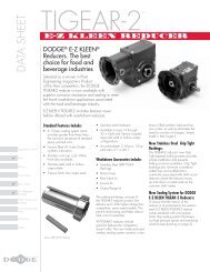
TIGEAR-2<br />
<strong>ENGINEERING</strong>/<strong>TECHNICAL</strong><br />
MAXUM Concentric Reducer<br />
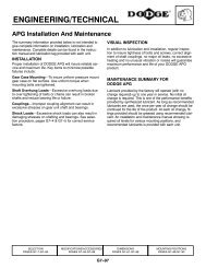
DODGE MAXUM Concentric Shaft Reducers can be<br />
modified to permit mounting in positions other than the<br />
conventional (A-1) floor mounting. Some of these include<br />
ceiling (A-3) and wall (A-2 and A-4) and various inclined,<br />
vertical and tilted positions. Consult DODGE to determine<br />
what modifications are required for your specific<br />
application.<br />
In order for DODGE to make re<strong>com</strong>mendations on the<br />
required modifications, the following information must be<br />
provided:<br />
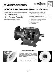
FEATURES/BENEFITS<br />
PAGE G3-3<br />
Angle Of Incline<br />
Specify Input or Output Shaft Up<br />
A-3<br />
A-2 Viewed from Output Shaft<br />
NOMENCLATURE<br />
PAGE G3-6<br />
G3-78<br />
Angle Of Tilt<br />
Specify Left or Right Side High<br />
When Viewed from Output Shaft<br />
• Reducer Size.<br />
• Ratio.<br />
• Input and/or output speed.<br />
• Transmitted Horsepower.<br />
• Duty cycle. Continuous or intermittent operation. If<br />
intermittent, running time vs. idle time.<br />
• Mounting position, such as A-2, A-3 or A-4 with shafts<br />
level, or a more <strong>com</strong>plete descri<strong>pt</strong>ion of the mounting<br />
arrangement including the angle of tilt of the housing,<br />
the incline of the shafts and whether the output shaft is<br />
higher or lower than the input shaft.<br />
EASY SELECTION<br />
PAGE G3-7<br />
A-4<br />
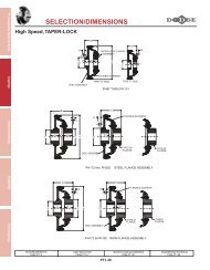
SELECTION/DIMENSIONS<br />
PAGE G3-23