ENGINEERING/TECHNICAL - Dodge-pt.com
ENGINEERING/TECHNICAL - Dodge-pt.com
ENGINEERING/TECHNICAL - Dodge-pt.com

Create successful ePaper yourself
Turn your PDF publications into a flip-book with our unique Google optimized e-Paper software.
Gearing Reference Guide<br />
TORQUE-ARM II<br />
TORQUE-ARM<br />
MAXUM Concentric Reducer<br />
TIGEAR-2<br />
<strong>ENGINEERING</strong>/<strong>TECHNICAL</strong><br />
MAXUM Concentric Reducer<br />
Step 4: Determine Unit Size and Ratio - Locate the<br />
horsepower table for 1750 high speed shaft rpm(Table 14,<br />
page G3-60). Trace down the ratio column to the closest<br />
nominal ratio to the 7.6:1 required ratio and find 7.59:1<br />
ratio. Trace to the right until the horsepower equals or<br />
exceeds the calculated equivalent horsepower of 250 and<br />
find 323 horsepower listed under a MAXUM size 7 reducer.<br />
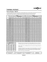
Step 5: Check Thermal Ratings - Because the 323<br />
mechanical horsepower rating for the MAXUM size 7<br />
reducer fell in the shaded area, the thermal capacity must<br />
be checked. Refer to the thermal horsepower rating tables<br />
on page G3-68. Locate the table for 1750 high speed shaft<br />
rpm and find the thermal ratings for the MAXUM size 7<br />
reducer. Note that the thermal rating without a fan is 150<br />
horsepower and that the thermal rating with a fan is 273<br />
horsepower. When a dash (-) is shown, the dash means<br />
that the thermal capacity exceeds the mechanical capacity.<br />
Since the actual transmitted horsepower of 200 exceeds<br />
the 150 thermal rating without a fan, an auxiliary cooling<br />
fan is required.<br />
Step 6: Check Overhung and Thrust Loads - Since both<br />
shafts are coupling connected, overhung or thrust loads<br />
are not applied.<br />
Step 7: Variable Speed Applications - Since this is a<br />
constant speed application, variable speed does not apply.<br />
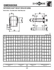
Step 8: Check Dimensions - Refer to the specifications/<br />
dimensions page G3-29 for DODGE MAXUM size 7<br />
reducers. The part number for the reducer is 299140 and<br />
for the auxiliary cooling fan is 299523. The exact ratio of<br />
the reducer is given in Table 24, page G3-74 and is<br />
7.527:1.<br />
TORQUE METHOD<br />
Running 10 hours a day, a scum breaker for a sewage<br />
disposal system requires 51,350 lb-in of torque at 230 rpm<br />
and has an overhung load of 6,710 pounds on the low<br />
speed shaft. The overhung load is located 4inches out from<br />
the reducer on the usable shaft extension. The motor<br />
speed is 1170 rpm and is coupling connected.<br />
Step 1: Determine Service Factor - From Table 2,<br />
Service Factors, locate “Sewage Disposal - Scum<br />
Breakers” and under the column headed “3-10 Hrs/Day<br />
Service” locate the service factor which is 1.50.<br />
Step 2: Calculate Equivalent Torque - Multiply the<br />
system torque of 51,350 by the service factor of 1.50<br />
FEATURES/BENEFITS<br />
PAGE G3-3<br />
NOMENCLATURE<br />
PAGE G3-6<br />
G3-58<br />
(51,350 x 1.50 = 77,025) to get 77,025 lb-in equivalent<br />
torque.<br />
Step 3: Calculate Required Ratio - Divide the high speed<br />
shaft rpm by the low speed shaft rpm (1170 / 230 = 5.09) to<br />
get the required ratio of 5.09:1.<br />
Step 4: Determine Unit Size and Ratio - Locate the<br />
torque table for 1170 high speed shaft rpm (Table 17, page<br />
G3-64). Trace down the ratio column to the closest nominal<br />
ratio to the 5.09:1 required ratio and find 5.06:1 ratio. Trace<br />
to the right until the torque equals or exceeds the<br />
calculated equivalent torque of 77,025 and find 77,700<br />
listed under a MAXUM size 7 reducer.<br />
Step 5: Check Thermal Ratings - Because the 77,700<br />
mechanical rating falls in the shaded area, the thermal<br />
ratings must be checked. First, convert the required torque<br />
without service factor (51,350) to horsepower at 230 rpm<br />
as follows:<br />
Horsepower = 510350 X 230 = 187 hp<br />
63025<br />
Locate the table for the thermal horsepower ratings at 1170<br />
high speed shaft rpm and find the MAXUM size 7 reducer<br />
with a 5.06 ratio. Since the 187 calculated horsepower<br />
exceeds the thermal rating shown without a fan, an<br />
auxiliary cooling fan is required.<br />
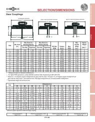
Step 6: Check Overhung and Thrust Loads - An<br />
overhung load of 6,710 pounds is on the low speed shaft. It<br />
must first be adjusted for it’s position on the shaft. Turn to<br />
Table 22, page G3-71 load location factors for low speed<br />
shafts and locate the 4 inch distance in the left hand<br />
column. Under the MAXUM 7 column find the load location<br />
factor of 1.06. Multiply the 6,710 overhung load by this<br />
factor (6,710 x 1.06 = 7,113) to get an equivalent overhung<br />
load of 7,113 pounds. Now turn to the output shaft<br />
overhung load Table 24, page G3-74 and locate 230 low<br />
speed shaft rpm in the left column. Trace right to the<br />
MAXUM size 7 reducer and find the overhung load<br />
capacity of 7,480 pounds. Since the capacity exceeds the<br />
equivalent overhung load, the selection is acce<strong>pt</strong>able.<br />
Step 7: Variable Speed Applications - Since this is a<br />
constant speed application, variable speed does not apply.<br />
Step 8: Check Dimensions - Refer to the specifications/<br />
dimensions page G3-29 for DODGE MAXUM size 7<br />
reducers. The part number for the reducer is 299138 and<br />
for the auxiliary cooling fan is 299523. The exact ratio of<br />
the reducer is given in Table 25 and is 5.065:1.<br />
EASY SELECTION<br />
PAGE G3-7<br />
SELECTION/DIMENSIONS<br />
PAGE G3-23