4 - KARB-TECH Kft
4 - KARB-TECH Kft
4 - KARB-TECH Kft

You also want an ePaper? Increase the reach of your titles
YUMPU automatically turns print PDFs into web optimized ePapers that Google loves.
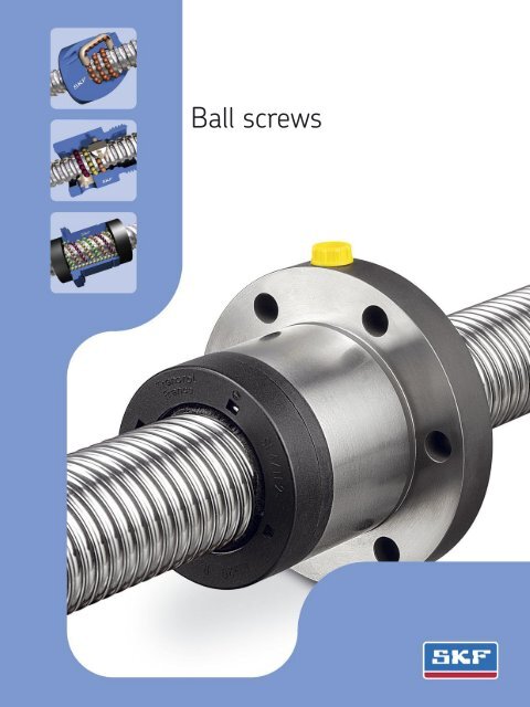
Ball screws
Medical equipment<br />
Press brakes<br />
EDM<br />
Woodworking<br />
2
General<br />
Contents<br />
d<br />
Ø<br />
Load C o<br />
Rolling<br />
element<br />
Recommendations for selection<br />
Overview: ball screw nuts --------------------------------------------------------------------------------------------------- 05<br />
Basic dynamic load rating (C a<br />
) --------------------------------------------------------------------------------------------- 05<br />
Static load carrying capacity (C oa<br />
) ----------------------------------------------------------------------------------------- 06<br />
Critical rotating speed for screw shafts ---------------------------------------------------------------------------------- 06<br />
Permissible speed limit ------------------------------------------------------------------------------------------------------ 07<br />
Lubrication ---------------------------------------------------------------------------------------------------------------------- 07<br />
Effi ciency and back-driving ------------------------------------------------------------------------------------------------- 07<br />
Axial play and preload -------------------------------------------------------------------------------------------------------- 08<br />
Static axial stiffness of a complete assembly --------------------------------------------------------------------------- 08<br />
Screw shaft buckling --------------------------------------------------------------------------------------------------------- 08<br />
Manufacturing precision ----------------------------------------------------------------------------------------------------- 09<br />
Materials and heat treatments ---------------------------------------------------------------------------------------------- 09<br />
1<br />
Recommendations for assembly<br />
Radial and moment loads ---------------------------------------------------------------------------------------------------- 10<br />
Alignment ----------------------------------------------------------------------------------------------------------------------- 10<br />
Lubrication ---------------------------------------------------------------------------------------------------------------------- 10<br />
Designing the screw shaft ends ------------------------------------------------------------------------------------------- 10<br />
Operating temperature ------------------------------------------------------------------------------------------------------ 10<br />
Separating the nut from the screw shaft -------------------------------------------------------------------------------- 11<br />
Starting-up the screw ------------------------------------------------------------------------------------------------------- 11<br />
2<br />
Other technical data<br />
Lead precision according to ISO -------------------------------------------------------------------------------------------- 12<br />
3<br />
Product information<br />
SD/BD miniature screws ---------------------------------------------------------------------------------------------------- 14<br />
SDS/BDS/SHS miniature screws in stainless steel ------------------------------------------------------------------- 16<br />
SH miniature screws --------------------------------------------------------------------------------------------------------- 18<br />
SX/BX universal screws ------------------------------------------------------------------------------------------------------ 20<br />
Accessories for SX/BX nuts ------------------------------------------------------------------------------------------------- 22<br />
SND/BND precision screws, DIN standard ------------------------------------------------------------------------------ 24<br />
PND preloaded screws, DIN standard ------------------------------------------------------------------------------------ 26<br />
SN/BN precision screws ----------------------------------------------------------------------------------------------------- 28<br />
PN preloaded screws --------------------------------------------------------------------------------------------------------- 30<br />
SL/BL long lead screws ------------------------------------------------------------------------------------------------------ 32<br />
SLT/BLT rotating nuts -------------------------------------------------------------------------------------------------------- 34<br />
Standard machined ends ---------------------------------------------------------------------------------------------------- 36<br />
Screw shaft accessories ----------------------------------------------------------------------------------------------------- 40<br />
Calculation formulas ---------------------------------------------------------------------------------------------------------- 46<br />
Designation --------------------------------------------------------------------------------------------------------------------- 49<br />
Roller screws and cylinders ------------------------------------------------------------------------------------------------- 50<br />
4<br />
3
Nuts for ball screws<br />
Nuts for ball screws<br />
Screw assembly<br />
Type of recirculation<br />
SD/BD<br />
Internal, by inserts<br />
Right hand lead<br />
Diameter<br />
8 2,5<br />
10 2 - 4<br />
12 2 - 4 - 5<br />
14 4<br />
16 2 - 5 - 10<br />
Catalogue page<br />
Screw accessories<br />
Nut accessories<br />
Preload for optimum rigidity<br />
Backlash elimination<br />
Axial play<br />
SD<br />
SD<br />
SD<br />
SD<br />
BD<br />
BD<br />
BD<br />
BD<br />
14<br />
SD BD<br />
yes<br />
SDS/BDS<br />
Stainless steel optional<br />
16<br />
SH<br />
External, by integrated tube<br />
6<br />
2<br />
SH<br />
18<br />
10<br />
3<br />
SH<br />
12,7<br />
12,7<br />
SH<br />
SHS<br />
Stainless steel optional<br />
16<br />
SX/BX<br />
Internal, by inserts<br />
20<br />
25<br />
32<br />
40<br />
50<br />
63<br />
5<br />
5 - 10<br />
5 - 10<br />
5 - 10<br />
10<br />
10<br />
SX<br />
SX<br />
SX<br />
SX<br />
SX<br />
SX<br />
BX<br />
BX<br />
BX<br />
BX<br />
BX<br />
BX<br />
yes<br />
yes<br />
yes<br />
yes<br />
yes<br />
yes<br />
yes<br />
yes<br />
yes<br />
yes<br />
yes<br />
yes<br />
20<br />
SND/BND/PND<br />
Internal, by inserts<br />
16<br />
20<br />
5 - 10<br />
5<br />
SND<br />
SND<br />
BND<br />
BND<br />
PND<br />
PND<br />
yes<br />
yes<br />
24<br />
25<br />
5 - 10<br />
SND<br />
BND<br />
PND<br />
yes<br />
32<br />
5 - 10<br />
SND<br />
BND<br />
PND<br />
yes<br />
40<br />
5 - 10<br />
SND<br />
BND<br />
PND<br />
yes<br />
DIN VERSION<br />
50<br />
63<br />
10<br />
10<br />
SND<br />
SND<br />
BND<br />
BND<br />
PND<br />
PND<br />
yes<br />
yes<br />
SN/BN/PN<br />
Internal, by inserts<br />
16<br />
20<br />
5<br />
5<br />
SN<br />
SN<br />
BN<br />
BN<br />
PN<br />
PN<br />
yes<br />
yes<br />
28<br />
25<br />
5 - 10<br />
SN<br />
BN<br />
PN<br />
yes<br />
32<br />
5 - 10<br />
SN<br />
BN<br />
PN<br />
yes<br />
40<br />
5 - 10<br />
SN<br />
BN<br />
PN<br />
yes<br />
50<br />
10<br />
SN<br />
BN<br />
PN<br />
yes<br />
63<br />
10<br />
SN<br />
BN<br />
PN<br />
yes<br />
SL/BL - SLD/BLD<br />
By faces<br />
25<br />
32<br />
32<br />
32<br />
40<br />
50<br />
20 - 25<br />
20 - 40<br />
32<br />
32<br />
20 - 40<br />
50<br />
SL<br />
SL<br />
SL<br />
SLD<br />
SL<br />
SL<br />
BL<br />
BL<br />
BL<br />
BLD<br />
BL<br />
BL<br />
yes<br />
yes<br />
yes<br />
yes<br />
yes<br />
yes<br />
32<br />
4<br />
SLT, BLT, Rotating nuts<br />
Accessories: FLBU, PLBU, BUF<br />
with SL/BL long lead screw<br />
34<br />
40
Recommendations for selection<br />
Recommendations for selection<br />
Only basic selection parameters are included. To make the very<br />
best selection of a ball screw, the designer should specify such critical<br />
parameters as the load profile, the linear or rotational speed,<br />
the rates of acceleration and deceleration, the cycle rate, the environment,<br />
the required life, the lead accuracy, the stiffness, and any<br />
other special requirement. If in doubt, please consult an SKF ball<br />
screw specialist before placing an order.<br />
1<br />
Basic dynamic load<br />
rating (C a<br />
)<br />
The dynamic rating is used to<br />
compute the fatigue life of ball<br />
screws. It is the axial load constant<br />
in magnitude and direction,<br />
and acting centrally under which<br />
the nominal life (as defi ned by<br />
ISO) reaches one million revolutions.<br />
Nominal fatigue life L 10<br />
The nominal life of a ball screw is<br />
the number of revolutions (or the<br />
number of operating hours at a<br />
given constant speed) which the<br />
ball screw is capable of enduring<br />
before the fi rst sign of fatigue<br />
(fl aking, spalling) occurs on one of<br />
the rolling surfaces.<br />
It is however evident from<br />
both laboratory tests and practical<br />
experience that seemingly<br />
identical ball screws operating<br />
under identical conditions have<br />
different lives, hence the notion<br />
of nominal life.<br />
It is, in accordance with ISO<br />
defi nition, the life achieved or<br />
exceeded by 90 % of a suffi ciently<br />
large group of apparently identical<br />
ball screws, working in identical<br />
conditions (alignment, axial<br />
and centrally applied load, speed,<br />
acceleration, lubrication, temperature<br />
and cleanliness).<br />
Service life<br />
The actual life achieved by a specifi<br />
c ball screw before it fails is<br />
known as “service life”. Failure is<br />
not only by fatigue (fl aking or<br />
spalling); but also by inadequate<br />
lubrication and wear; wear of the<br />
recirculation system, corrosion,<br />
contamination, and, more generally,<br />
by loss of the functional<br />
characteristics required by the<br />
application. Experience acquired<br />
with similar applications will help<br />
to select the proper screw to<br />
obtain the required service life.<br />
One must also take into account<br />
structural requirements such as<br />
the strength of screw ends and<br />
nut attachments, due to the<br />
loads applied on these elements<br />
in service. To attain L 10<br />
life performance<br />
a mean working load of<br />
up to 80 % of C a<br />
and a stroke<br />
higher than 4 leads are permitted.<br />
Life test bench<br />
(1) SKF can help you to define this value in relation with the actual conditions of service.<br />
5
Recommendations for selection<br />
Equivalent dynamic loads<br />
The loads acting on the screw<br />
can be calculated according to the<br />
laws of mechanics if the external<br />
forces (e.g. power transmission,<br />
work, rotary and linear inertia<br />
forces) are known or can be calculated.<br />
It is necessary to calculate<br />
the equivalent dynamic load.<br />
Radial and moment loads<br />
must be taken by linear bearing<br />
systems. It is extremely important<br />
to resolve these problems at the<br />
earliest conceptual stage. These<br />
forces are detrimental to the life<br />
and the expected performance of<br />
the screw.<br />
Fluctuating load<br />
When the load fl uctuates during<br />
the working cycle, it is necessary<br />
to calculate the equivalent dynamic<br />
load: this load is defi ned as<br />
that hypothetical load, constant in<br />
magnitude and direction, acting<br />
axially and centrally on the screw<br />
which, if applied, would have the<br />
same infl uence on the screw life<br />
as the actual loads to which the<br />
screw is subjected.<br />
Additional loads due, for<br />
example to misalignment, uneven<br />
loading, shocks, and so on, must<br />
be taken in account.<br />
Their infl uence on the nominal<br />
life of the screw is generally taken<br />
care of, consult SKF for advice.<br />
Static load carrying<br />
capacity (C oa<br />
)<br />
d<br />
Ø<br />
Load C o<br />
Rolling<br />
element<br />
Ball screws should be selected on<br />
the basis of the basic static load<br />
rating C oa<br />
instead of on bearing<br />
life when they are submitted to<br />
continuous or intermittent shock<br />
loads, while stationary or rotating<br />
at very low speed for short duration.<br />
The permissible load is<br />
determined by the permanent<br />
deformation caused by the load<br />
acting at the contact points.<br />
It is defi ned by ISO standards<br />
as the purely axially and centrally<br />
applied static load which will<br />
create, by calculation, a total (rolling<br />
element + thread surface)<br />
permanent deformation equal to<br />
0.0001 of the diameter of the<br />
rolling element.<br />
A ball screw must be selected<br />
by its basic static load rating<br />
which must be, at least, equal to<br />
the product of the maximum<br />
axial static load applied and a<br />
safety factor “s o<br />
”.<br />
The safety factor is selected in<br />
relation with past experience of<br />
similar applications and requirements<br />
of running smoothness<br />
and noise level (1).<br />
Critical rotating speed<br />
for screw shafts<br />
The shaft is equated to a cylinder,<br />
the diameter of which is the root<br />
diameter of the thread. The formulas<br />
use a parameter the value<br />
of which is dictated by the mounting<br />
of the screw shaft (whether<br />
it is simply supported or fi xed).<br />
As a rule the nut is not considered<br />
as a support of the screw<br />
shaft. Because of the potential<br />
inaccuracies in the mounting of<br />
the screw assembly, a safety<br />
factor of 0.80 is applied to the<br />
calculated critical speeds.<br />
Calculations which consider<br />
the nut as a support of the shaft,<br />
or reduce the safety factor, require<br />
practical tests and possibly an<br />
optimization of the design (1).<br />
(1) SKF can help you to define this value in relation with the actual conditions of service.<br />
6
Recommendations for selection<br />
Permissible speed limit<br />
Lubrication<br />
Efficiency and back-driving<br />
The permissible speed limit is<br />
that speed which a screw cannot<br />
reliably exceed at any time. It is<br />
generally the limiting speed of<br />
the recirculation system in the<br />
nut. It is expressed as the product<br />
of the rpm and the nominal diameter<br />
of the screw shaft (in mm).<br />
The speed limits quoted in this<br />
catalogue are the maximum<br />
speeds that may be applied<br />
through very short periods and<br />
in optimized running conditions<br />
of alignment, light external load<br />
and preload with monitored<br />
lubrication.<br />
Running a screw continuously<br />
at the permissible speed limit<br />
may lead to a reduction of the<br />
calculated life of the nut mechanism.<br />
!<br />
High speed associated with<br />
high load requires a large input<br />
torque and yields a relatively<br />
short nominal life (1).<br />
In the case of high acceleration<br />
and deceleration, it is recommended<br />
to either work under a<br />
nominal external load or to apply<br />
a light preload to the nut to avoid<br />
internal sliding during reversal.<br />
The value of preload of screws<br />
submitted to high velocity must<br />
be that preload which ensures<br />
that the rolling elements do not<br />
slide (1).<br />
Too high a preload will create<br />
unacceptable increases of the<br />
internal temperature.<br />
The lubrication of screws rotating<br />
at high speed must be properly<br />
considered in quantity and quality.<br />
The volume, spread and frequency<br />
of the application of the<br />
lubricant (oil or grease) must be<br />
properly selected and monitored.<br />
At high speed the lubricant<br />
spread on the surface of the<br />
screw shaft may be thrown off by<br />
centrifugal forces. It is important<br />
to monitor this phenomenon<br />
during the fi rst run at high speed<br />
and possibly adapt the frequency<br />
of relubrication or the fl ow of<br />
lubricant, or select a lubricant<br />
with a different viscosity.<br />
Monitoring the steady temperature<br />
reached by the nut permits<br />
the frequency of relubrication or<br />
the oil fl ow rate to be optimized.<br />
The performance of a screw is<br />
mainly dependant on the geometry<br />
of the contact surfaces and<br />
their fi nish as well as the helix<br />
angle of the thread. It is, also,<br />
dependant on the working conditions<br />
of the screw (load, speed,<br />
lubrication, preload, alignment,<br />
etc…).<br />
The “direct effi ciency” is used<br />
to defi ne the input torque required<br />
to transform the rotation of<br />
one member into the translation<br />
of the other. Conversely, the<br />
“indirect effi ciency” is used to<br />
defi ne the axial load required to<br />
transform the translation of one<br />
member into the rotation of the<br />
other one. It is used, also, to defi -<br />
ne the braking torque required to<br />
prevent that rotation.<br />
It is safe to consider that these<br />
screws are reversible or backdriveable<br />
under almost all<br />
circumstances.<br />
It is therefore necessary to<br />
design a brake mechanism if<br />
backdriving is to be avoided (gear<br />
reducers or brake).<br />
Friction Back driving<br />
torque T f<br />
> torque T r<br />
1<br />
(1) SKF can help you to define this value in relation with the actual conditions of service.<br />
7
Recommendations for selection<br />
Preload torque:<br />
Internally preloaded screws exhibit<br />
a torque due to this preload.<br />
This persists even when they are<br />
not externally loaded. Preload<br />
torque is measured when assembly<br />
is lubricated with ISO grade<br />
64 oil.<br />
Starting torque:<br />
This is defi ned as the torque needed<br />
to overcome the following to<br />
start rotation:<br />
a) the total inertia of all moving<br />
parts accelerated by the energy<br />
source (including rotation and<br />
linear movement).<br />
b) the internal friction of the<br />
screw/nut assembly, bearing and<br />
associated guiding devices.<br />
In general, torque to overcome<br />
inertia (a) is greater than friction<br />
torque (b).<br />
The coeffi cient of friction of<br />
the high effi ciency screw when<br />
starting µ s<br />
is estimated at up to<br />
double the dynamic coeffi cient µ,<br />
under normal conditions of use.<br />
Axial play and preload<br />
Preloaded nuts are subject to<br />
much less elastic deformation<br />
than non-preloaded nuts.<br />
Therefore they should be used<br />
whenever the accuracy of positioning<br />
under load is important.<br />
Preload is that force applied to<br />
a set of two half nuts to either<br />
press them together or push<br />
them apart with the purpose of<br />
eliminating backlash or increasing<br />
the rigidity or stiffness of the<br />
assembly. The preload is defi ned<br />
by the value of the preload torque<br />
(see under that heading in the<br />
previous paragrah). The torque<br />
depends on the type of nut and<br />
on the mode of preload (elastic or<br />
rigid).<br />
Static axial stiffness of a<br />
complete assembly<br />
It is the ratio of the external axial<br />
load applied to the system and<br />
the axial displacement of the face<br />
of the nut in relation with the<br />
fi xed (anchored) end of the screw<br />
shaft. The inverse of the rigidity<br />
of the total system is equal to the<br />
sum of all the inverses of the<br />
rigidity of each of the components<br />
(screw shaft, nut as mounted<br />
on the shaft, supporting<br />
bearing, supporting housings,<br />
etc…).<br />
Because of this, the rigidity of<br />
the total system is always less than<br />
the smallest individual rigidity.<br />
Nut rigidity<br />
When a preload is applied to a<br />
nut, fi rstly, the internal play is eliminated,<br />
then, the Hertzian elastic<br />
deformation increases as the<br />
preload is applied so that the<br />
overall rigidity increases.<br />
The theoretical deformation<br />
does not take into account<br />
machining inaccuracies, actual<br />
sharing of the load between the<br />
different contact surfaces, the<br />
elasticity of the nut and of the<br />
screw shaft. The practical stiffness<br />
values given in the catalogue<br />
are lower than the theoretical<br />
values for this reason. The rigidity<br />
values given in the SKF ball screw<br />
catalogue are individual practical<br />
values for the assembled nut.<br />
They are determined by SKF<br />
based on the value of the selected<br />
basic preload and an external<br />
load equal to twice this preload.<br />
Lead<br />
Nut<br />
Lead + Shift<br />
Lead<br />
Elastic deformation of screw<br />
shaft<br />
This deformation is proportional<br />
to its length and inversely proportional<br />
to the square of the<br />
root diameter.<br />
According to the relative<br />
importance of the screw deformation<br />
(see rigidity of the total<br />
system), too large an increase in<br />
the preload of the nut and supporting<br />
bearings yields a limited<br />
increase of rigidity and notably<br />
increases the preload torque and<br />
therefore the running temperature.<br />
Consequently, the preload stated<br />
in the catalogue for each<br />
dimension is optimum and should<br />
not be increased.<br />
Screw shaft buckling<br />
The column loading of the screw<br />
shaft must be checked when it is<br />
submitted to compression loading<br />
(whether dynamically or statically).<br />
The maximum permissible<br />
compressive load is calculated<br />
using the Euler formulas. It is<br />
then multiplied by a safety factor<br />
of 3 to 5, depending on the<br />
application.<br />
The type of end mounting of<br />
the shaft is critical to select the<br />
proper coeffi cients to be used in<br />
the Euler formulas.<br />
When the screw shaft comprises<br />
a single diameter, the root<br />
diameter is used for the calculation.<br />
When the screw comprises<br />
different sections with various<br />
diameters, calculations becomes<br />
more complex (1).<br />
Screw<br />
(1) SKF can help you to define this value in relation with the actual conditions of service.<br />
8
Recommendations for selection<br />
Manufacturing precision<br />
Generally speaking, the precision<br />
indication given in the designation<br />
defi nes the lead precisions<br />
see page 12 - lead precision<br />
according to ISO - (ex. G5 -<br />
G7…).<br />
Parameters other than lead<br />
precision correspond to our internal<br />
standards (generally based on<br />
ISO “class 7”).<br />
If you require special tolerances<br />
(for example class 5) please<br />
specify when requesting a quotation<br />
or ordering.<br />
Materials and heat<br />
treatments<br />
Standard screw shafts are<br />
machined from steel which is<br />
surface hardened by induction<br />
(42CrMo4-NF EN10083-1 for<br />
diameters > 16 mm and C45E<br />
for diameters ≤ 16 mm).<br />
Standard nuts are machined<br />
in steel which is through hardened<br />
(100 Cr6 - NFA 35.565 or<br />
equivalent for diameters ≥ 20 mm<br />
and carbon steel for diameters<br />
< 20 mm). Hardness of the contact<br />
surfaces is 56-60 HRc,<br />
depending on diameter, for standard<br />
screws.<br />
Most assemblies made of<br />
stainless material have a surface<br />
hardness in the range 50 to<br />
58 HRc, depending on the type.<br />
The load rating of the catalogue<br />
are given only for standard<br />
screws.<br />
Number of circuits of<br />
balls<br />
A nut is defi ned by the number of<br />
ball turns which support the load.<br />
The number is changing,<br />
according to the product and the<br />
combination diameter/lead.<br />
It is defi ned by the number of<br />
circuits and their type.<br />
Recirculation inserts<br />
The standard products have been<br />
fi tted with composite ball recirculation<br />
inserts.<br />
System performance is improved<br />
because of the smoother ball<br />
recirculation. This results from<br />
the improved precision of the<br />
moulded insert when compared<br />
to the former steel insert. If the<br />
product is used in severe applications,<br />
or the insert is used to<br />
prevent collapse (especially in<br />
vertical applications), a steel<br />
version is available. In such cases,<br />
the specifi er should consult SKF<br />
Linear Motion to obtain the optimum<br />
solution.<br />
1<br />
Working environment<br />
Our products have not been<br />
developed for use in an explosive<br />
atmosphere, consequently we<br />
cannot take any responsability for<br />
the use in this fi eld.<br />
NOTE: 42 CrMo4, an AFNOR<br />
reference is similar to AISI 4140;<br />
100Cr6 is similar to AISI 52100.<br />
(1) SKF can help you to define this value in relation with the actual conditions of service.<br />
9
Recommendations for assembly<br />
Recommended assembly procedure<br />
Ball screws are precision components and should be handled with<br />
care to avoid shocks. When stored out of the shipping crate they<br />
must lie on wooden or plastic vee blocks and should not be allowed<br />
to sag. Screw assemblies are shipped, wrapped in a heavy gauge<br />
plastic tube which protects them from foreign material and possible<br />
pollution. They should stay wrapped until they are used.<br />
Radial and moment loads<br />
Any radial or moment load on the<br />
nut will overload some of the<br />
contact surfaces, thus signifi cantly<br />
reducing life (fi g. 1).<br />
Alignment<br />
SKF linear guidance components<br />
should be used to ensure correct<br />
alignment and avoid non-axial<br />
loading. The parallelism of the<br />
screw shaft with the guiding devices<br />
must be checked. If external<br />
linear guidance proves impractical,<br />
we suggest mounting the nut<br />
on trunnions or gimbals and the<br />
screw shaft in self-aligning bearings.<br />
Mounting the screw in tension<br />
helps align it properly and eliminates<br />
buckling.<br />
Designing the screw shaft ends<br />
Generally speaking, when the<br />
ends of the screw shaft are<br />
specifi ed by the customer’s engineering<br />
personnel, it is their responsability<br />
to check the strength<br />
of these ends. However, we offer<br />
in pages 36 to 39 of this catalogue,<br />
a choice of standard machined<br />
ends. As far as possible, we<br />
recommend their use.<br />
Whatever your choice may be,<br />
please keep in mind that no<br />
dimension on the shaft ends can<br />
exceed d o<br />
(otherwise traces of<br />
the root of thread will appear or<br />
the shaft must be made by joining<br />
2 pieces).<br />
A minimum shoulder should<br />
be suffi cient to maintain the<br />
internal bearing.<br />
Operating at high temperature<br />
will lower the hardness of the<br />
steel, alter the accuracy of the<br />
thread and may increase the oxidability<br />
of the materials or change<br />
lubricant properties.<br />
Lubrication<br />
Good lubrication is essential for<br />
the proper functioning of the<br />
screw and for its long term reliability<br />
(1).<br />
Before shipping, the screw is<br />
coated with a protective fl uid that<br />
dries to a fi lm. This protective fi lm<br />
is not a lubricant.<br />
Depending on the selected<br />
lubricant, it may be necessary to<br />
remove this fi lm before applying<br />
the lubricant (there may be a risk<br />
of non-compatibility).<br />
If this operation is performed<br />
in a potentially polluted atmosphere<br />
it is highly recommended<br />
to proceed with a thorough cleaning<br />
of the assembly.<br />
Operating temperature<br />
Screws made from standard steel<br />
(see page 9) and operating under<br />
normal loads can sustain temperatures<br />
in the range -20 °C to<br />
+110 °C.<br />
Between +110 °C and +130 °C,<br />
SKF must be notifi ed so that it<br />
adapts the annealing procedure<br />
and checks that the application<br />
can be successful with a hardness<br />
below the standard minimum<br />
value (see page 9).<br />
Above +130 °C, steels adapted<br />
to the temperature of the application<br />
should be selected<br />
(100Cr6, special steel, etc…).<br />
Consult SKF for advice.<br />
fig. 1<br />
YES!<br />
Axial loads<br />
fig. 2<br />
NO!<br />
Radial loads<br />
(1) SKF can help you to define this value in relation with the actual conditions of service.<br />
10
Recommendations for assembly<br />
Separating the nut from the<br />
screw shaft<br />
Never screw the nut off the shaft<br />
without a mandrel to prevent the<br />
balls coming out (fi g. 1).<br />
1. Remove the retaining strap<br />
2. Hold the sleeve against the ball<br />
track (a). If the sleeve does not<br />
go over the diameter next to<br />
the ball track, adhesive tape<br />
can be used (b) or the sleeve<br />
held against the unmachined<br />
end (c). (fi g. 2)<br />
3. Without forcing, engage the<br />
nut in the screw thread.<br />
a<br />
fig. 1<br />
fig. 2<br />
Starting-up the screw<br />
After the assembly has been<br />
cleaned, mounted and lubricated,<br />
it is recommended that the nut is<br />
allowed to make several full strokes<br />
at low speed; to check the<br />
proper positioning of the limit<br />
switches or reversing mechanism<br />
before applying the full load and<br />
the full speed.<br />
NOTE:<br />
Intructions for most operations<br />
like mounting a nut on a screw<br />
shaft, a wiper on a nut, etc… are<br />
available in separate sheets delivered<br />
with the product: please<br />
refer to them.<br />
b<br />
c<br />
2<br />
11
Standard technical data<br />
Lead precision according to ISO<br />
Lead precision is measured at 20 °C on the useful stroke l u<br />
, which is<br />
the threaded length decreased, at each end, by the length l e<br />
equal to<br />
the screw shaft diameter.<br />
G5 G7 G9<br />
V 300p<br />
µm 23 35 87<br />
l u<br />
e p<br />
v up<br />
e p<br />
v up<br />
e p<br />
v up<br />
mm µm<br />
0 - 315 23 23 52 35 130 87<br />
(315) - 400 25 25 57 40 140 100<br />
(400) - 500 27 26 63 46 155 115<br />
(500) - 630 32 29 70 52 175 130<br />
(630) - 800 36 31 80 57 200 140<br />
(800) - 1000 40 34 90 63 230 155<br />
(1000) - 1250 47 39 105 70 260 175<br />
(1250) - 1600 55 44 125 80 310 200<br />
(1600) - 2000 65 51 150 90 370 230<br />
(2000) - 2500 78 59 175 105 440 260<br />
(2500) - 3150 96 69 210 125 530 310<br />
(3150) - 4000 115 82 260 150 640 370<br />
(4000) - 5000 140 99 320 175 790 440<br />
(5000) - 6000 170 119 390 210 960 530<br />
Lead accuracy control on a complete assembly<br />
12
Standard technical data<br />
l u<br />
l e<br />
l o<br />
l s<br />
= useful travel<br />
= excess travel (no lead precision required)<br />
= nominal travel<br />
= specifi ed travel<br />
c = travel compensation (difference between l s<br />
and l o<br />
to<br />
be defi ned by the customer, for instance to<br />
compensate an expansion)<br />
e p<br />
= tolerance over the specifi ed travel<br />
V = travel variation (or permissible band width)<br />
V 300p<br />
= maximum permitted travel variation over 300 mm<br />
= maximum permitted travel variation over the useful<br />
V up<br />
travel l u<br />
V 300a<br />
= measured travel variation over 300 mm<br />
= measured travel variation over the useful travel<br />
V ua<br />
fig. 1<br />
l e<br />
Mean travel :<br />
the line which fits<br />
the curve best by<br />
method of least<br />
squares.<br />
v300a<br />
µm<br />
+<br />
Threaded length<br />
l u<br />
l e<br />
mm l 0<br />
v up<br />
+ v ua<br />
-<br />
l m<br />
v 300p<br />
300 mm<br />
Case with value of c specified by the customer.<br />
fig. 2<br />
Case with c = 0 = standard version in case of<br />
no value given by the customer.<br />
fig. 3<br />
3<br />
le<br />
Threaded length<br />
l u<br />
m<br />
+<br />
l e<br />
mm<br />
l 0<br />
l e<br />
Threaded length<br />
l u<br />
m<br />
+<br />
l e<br />
e p v up<br />
e p<br />
c<br />
l m<br />
v up<br />
e p<br />
l 0<br />
mm<br />
e p<br />
-<br />
l s<br />
-<br />
13
Product information<br />
SD/BD miniature screws<br />
Standard Recirculation Customised<br />
Smooth running and excellent backdriving with the<br />
new SD/BD internal recirculation nut.<br />
• Nominal diameter<br />
8 to 16 mm<br />
• Lead: 2 to 10 mm<br />
• Cylindrical nut with threaded<br />
end: easy mounting<br />
• Excellent repeatibility:<br />
high positioning quality<br />
• Internal recirculation with<br />
inserts: smooth running and<br />
good backdriving<br />
• Backlash elimination by<br />
oversize balls on request<br />
(BD designation): maximum<br />
length 1000 mm<br />
• Optional safety device (*):<br />
12x4R - 14x4R - 16x5R<br />
• Optional wipers (*):<br />
For all sizes<br />
• Corrosion resistant screw<br />
(see page 16)<br />
(*) It is not possible to supply safety<br />
device and wipers in the same nut.<br />
Nominal Right Maximum Basic load ratings Number Maximum Reduced Mass Mass Inertia Designation<br />
diameter hand length of circuits axial maximum of nut of screw of one<br />
lead dynamic static of balls play axial play shaft metre of<br />
(on request)<br />
screw shaft<br />
d 0<br />
P h<br />
C a<br />
C oa<br />
mm mm mm kN kN — mm kg kg/m kgmm 2<br />
8<br />
2,5<br />
1000<br />
2,2<br />
2,6<br />
3<br />
0,07<br />
0,03<br />
0,025<br />
0,32<br />
2,1<br />
SD/BD 8x2,5 R<br />
10<br />
10<br />
2<br />
4<br />
1000<br />
1000<br />
2,5<br />
4,5<br />
3,5<br />
5,4<br />
3<br />
3<br />
0,07<br />
0,07<br />
0,03<br />
0,03<br />
0,030<br />
0,040<br />
0,51<br />
0,43<br />
5,2<br />
3,8<br />
SD/BD 10x2 R<br />
SD/BD 10x4 R<br />
12<br />
12<br />
12<br />
2<br />
4<br />
5<br />
2000<br />
2000<br />
2000<br />
2,9<br />
5,0<br />
4,2<br />
4,6<br />
6,5<br />
5,3<br />
3<br />
3<br />
3<br />
0,07<br />
0,07<br />
0,07<br />
0,03<br />
0,03<br />
0,03<br />
0,023<br />
0,066<br />
0,058<br />
0,67<br />
0,71<br />
0,71<br />
10,0<br />
10,8<br />
10,1<br />
SD/BD 12x2 R<br />
SD/BD 12x4 R<br />
SD/BD 12x5 R<br />
14<br />
4<br />
2000<br />
6,0<br />
9,0<br />
3<br />
0,07<br />
0,03<br />
0,083<br />
1,05<br />
22,0<br />
SD/BD 14x4 R<br />
16<br />
16<br />
16<br />
2<br />
5<br />
10<br />
2000<br />
2000<br />
2000<br />
3,3<br />
7,6<br />
10,7<br />
6,2<br />
10,5<br />
17,0<br />
3<br />
3<br />
21,8<br />
0,07<br />
0,07<br />
0,07<br />
0,03<br />
0,03<br />
0,03<br />
0,100<br />
0,135<br />
0,160<br />
1,40<br />
1,30<br />
1,21<br />
39,7<br />
33,9<br />
30,7<br />
SD/BD 16x2 R<br />
SD/BD 16x5 R<br />
SD/BD 16x10 R<br />
14
Product information<br />
SD<br />
BD<br />
A<br />
A 1<br />
N<br />
A 2<br />
D3<br />
d 0<br />
d 1<br />
d 2<br />
D2<br />
M<br />
D<br />
Designation Screw shaft Nut Without With Tightening Without<br />
wiper wipers spanner wiper<br />
4<br />
— mm<br />
d 2<br />
d 1<br />
D M A +/-0,3 A 2<br />
(FACOM) N A 1<br />
D 2<br />
D 3<br />
h10 6g ± 0,2<br />
SD/BD 8x2,5 R<br />
6,3<br />
7,6<br />
17,5<br />
M15x1<br />
23,5<br />
23,5<br />
7,5<br />
126-A35<br />
3,2<br />
3<br />
11,1<br />
11,1<br />
SD/BD 10x2 R<br />
SD/BD 10x4 R<br />
8,3<br />
7,4<br />
9,5<br />
8,9<br />
19,5<br />
21,0<br />
M17x1<br />
M18x1<br />
22,0<br />
28,0<br />
22,0<br />
-<br />
7,5<br />
8,0<br />
126-A35<br />
126-A35<br />
3,2<br />
3,2<br />
3<br />
3<br />
13,3<br />
13,0<br />
13,3<br />
-<br />
SD/BD 12x2 R<br />
SD/BD 12x4 R<br />
SD/BD 12x5 R<br />
9,9<br />
9,4<br />
9,3<br />
11,2<br />
11,3<br />
11,8<br />
20,0<br />
25,5<br />
23,0<br />
M18x1<br />
M20x1<br />
M20x1<br />
20,0<br />
34,0<br />
36,0<br />
23,5<br />
34,0<br />
40,0<br />
8,0<br />
10,0<br />
10,0<br />
126-A35<br />
126-A35<br />
126-A35<br />
3,2<br />
3,2<br />
3,2<br />
3<br />
3<br />
3<br />
13,2<br />
16,1<br />
-<br />
-<br />
16,1<br />
-<br />
SD/BD 14x4 R<br />
11,9<br />
13,7<br />
27,0<br />
M22x1,5<br />
30,0<br />
34,0<br />
8,0<br />
126-A35<br />
3,2<br />
3<br />
-<br />
-<br />
SD/BD 16x2 R<br />
SD/BD 16x5 R<br />
SD/BD 16x10 R<br />
14,3<br />
12,7<br />
12,6<br />
15,6<br />
15,2<br />
15,2<br />
29,5<br />
32,5<br />
32,0<br />
M25x1,5<br />
M26x1,5<br />
M26x1,5<br />
27,0<br />
42,0<br />
46,0<br />
27,0<br />
42,0<br />
46,0<br />
12,0<br />
12,0<br />
12,0<br />
126-A35<br />
126-A35<br />
126-A35<br />
3,2<br />
3,2<br />
3,2<br />
3<br />
3<br />
3<br />
20,1<br />
-<br />
19,5<br />
20,1<br />
21,1<br />
19,5<br />
Designation: see page 49<br />
15
Product information<br />
SDS/BDS/SHS miniature screws in stainless steel<br />
Standard SDS Standard SHS Customised SDS<br />
• Nominal diameter<br />
6 to 16 mm<br />
• Lead: 2 to 5 mm<br />
• Cylindrical nut with threaded<br />
end: easy mounting<br />
• Excellent repeatibility:<br />
high positioning quality<br />
• Backlash elimination by<br />
oversize balls on request<br />
(BDS designation): maximum<br />
length 1000 mm<br />
• Optional wipers:<br />
For all sizes<br />
• Material for both shaft and nut:<br />
X30Cr13 (AISI 420 equivalent)<br />
• Balls are in X105CrMo17 (AISI<br />
440C equivalent) except for size<br />
16x5R (SDS/BDS): balls are in<br />
100 Cr6 (AISI 52100 equivalent)<br />
Nominal Right Maximum Basic load ratings Number Maximum Reduced Mass Mass Inertia Designation<br />
diameter hand length of circuits axial maximum of nut of screw of one<br />
lead dynamic static of balls play axial play shaft metre of<br />
(on request)<br />
screw shaft<br />
d 0<br />
P h<br />
C a<br />
C oa<br />
mm mm mm kN kN — mm kg kg/m kgmm 2<br />
6<br />
2<br />
1000<br />
1,0<br />
1,1<br />
1 x 2,5<br />
0,05<br />
0,02<br />
0,025<br />
0,18<br />
0,7<br />
SHS 6x2 R<br />
8<br />
2,5<br />
1000<br />
1,2<br />
1,3<br />
3<br />
0,07<br />
0,03<br />
0,024<br />
0,32<br />
2,1<br />
SDS/BDS 8x2,5 R<br />
10<br />
2<br />
1000<br />
1,6<br />
1,7<br />
3<br />
0,07<br />
0,03<br />
0,026<br />
0,51<br />
5,2<br />
SDS/BDS 10x2 R<br />
12<br />
12<br />
12<br />
2<br />
4<br />
5<br />
2000<br />
2000<br />
2000<br />
1,8<br />
3,0<br />
2,5<br />
2,2<br />
3,2<br />
2,6<br />
3<br />
3<br />
3<br />
0,07<br />
0,07<br />
0,07<br />
0,03<br />
0,03<br />
0,03<br />
0,028<br />
0,068<br />
0,061<br />
0,67<br />
0,71<br />
0,71<br />
10,0<br />
10,8<br />
10,1<br />
SDS/BDS 12x2 R<br />
SDS/BDS 12x4 R<br />
SDS/BDS 12x5 R<br />
14<br />
4<br />
2000<br />
3,7<br />
4,4<br />
3<br />
0,07<br />
0,03<br />
0,075<br />
1,05<br />
22,0<br />
SDS/BDS 14x4 R<br />
16<br />
16<br />
2<br />
5<br />
2000<br />
2000<br />
2,0<br />
4,7<br />
3,0<br />
5,1<br />
3<br />
3<br />
0,07<br />
0,07<br />
0,03<br />
0,03<br />
0,066<br />
0,133<br />
1,40<br />
1,30<br />
39,7<br />
33,9<br />
SDS/BDS 16x2 R<br />
SDS/BDS 16x5 R<br />
16
Product information<br />
SDS<br />
BDS<br />
A<br />
A 1<br />
N<br />
A 2<br />
D3<br />
d 0<br />
d 1<br />
d 2<br />
D2<br />
M<br />
D<br />
Designation Screw shaft Nut Without With Tightening Without<br />
wiper wipers spanner wiper<br />
4<br />
— mm<br />
d 2<br />
d 1<br />
D M A +/-0,3 A 2<br />
(FACOM) N A 1<br />
D 2<br />
D 3<br />
h10 6g ± 0,2<br />
SHS 6x2 R<br />
4,7<br />
6,0<br />
16,5<br />
M14x1,0<br />
20<br />
-<br />
7,5<br />
126-A35<br />
3,2<br />
3<br />
8,3<br />
-<br />
SDS/BDS 8x2,5 R<br />
6,3<br />
7,6<br />
17,5<br />
M15x1,0<br />
23,5<br />
23,5<br />
7,5<br />
126-A35<br />
3,2<br />
3<br />
11,1<br />
11,1<br />
SDS/BDS 10x2 R<br />
8,3<br />
9,5<br />
19,5<br />
M17x1,0<br />
22,0<br />
22,0<br />
7,5<br />
126-A35<br />
3,2<br />
3<br />
13,3<br />
13,3<br />
SDS/BDS 12x2 R<br />
SDS/BDS 12x4 R<br />
SDS/BDS 12x5 R<br />
9,9<br />
9,4<br />
9,3<br />
11,2<br />
11,3<br />
11,8<br />
20,0<br />
25,5<br />
23,0<br />
M18x1,0<br />
M20x1,0<br />
M20x1,0<br />
23,5<br />
34,0<br />
40,0<br />
23,5<br />
34,0<br />
40,0<br />
8,0<br />
10,0<br />
10,0<br />
126-A35<br />
126-A35<br />
126-A35<br />
3,2<br />
3,2<br />
3,2<br />
3<br />
3<br />
3<br />
13,2<br />
16,1<br />
16,1<br />
13,2<br />
16,1<br />
16,1<br />
SDS/BDS 14x4 R<br />
11,9<br />
13,7<br />
27,0<br />
M22x1,5<br />
34,0<br />
34,0<br />
8,0<br />
126-A35<br />
3,2<br />
3<br />
17,5<br />
17,5<br />
SDS/BDS 16x2 R<br />
SDS/BDS 16x5 R<br />
14,3<br />
12,7<br />
15,5<br />
15,2<br />
29,5<br />
32,5<br />
M25x1,5<br />
M26x1,5<br />
27,0<br />
42,0<br />
27,0<br />
42,0<br />
12,0<br />
12,0<br />
126-A35<br />
126-A35<br />
3,2<br />
3,2<br />
3<br />
3<br />
20,1 20,1<br />
21,1 21,1<br />
Designation: see page 49<br />
17
Product information<br />
SH miniature screws<br />
Standard Recirculation Customised<br />
Rolled thread ball screw with ball recirculation by<br />
integrated tube.<br />
• Nominal diameter<br />
6 to 12,7 mm<br />
• Lead: 2 to 12,7 mm<br />
• Nut with threaded end for easy<br />
mounting<br />
• High positioning accuracy<br />
• Increased security: optional<br />
reinforced safety device<br />
available on request in size<br />
SH 12,7x12,7R<br />
• Wipers available on request for<br />
size SH 12,7x12,7R<br />
It is not possible to supply safety device<br />
and wipers in the same nut.<br />
Nominal Right Maximum Basic load ratings Number Maximum Reduced Mass Mass Inertia Designation<br />
diameter hand length of circuits axial maximum of nut of screw of one<br />
lead dynamic static of balls play axial play shaft metre of<br />
(on request)<br />
screw shaft<br />
d 0<br />
P h<br />
C a<br />
C oa<br />
mm mm mm kN kN — mm mm kg kg/m kgmm 2<br />
6<br />
2<br />
1000<br />
1,2<br />
1,5<br />
1 x 2,5<br />
0,05<br />
0,02<br />
0,025<br />
0,18<br />
0,7<br />
SH 6 x 2 R<br />
10<br />
3<br />
1000<br />
2,3<br />
3,5<br />
1 x 2,5<br />
0,07<br />
0,03<br />
0,050<br />
0,50<br />
5,1<br />
SH 10 x 3 R<br />
12,7<br />
12,7<br />
2000<br />
5,3<br />
9,0<br />
2 x 1,5<br />
0,07<br />
0,03<br />
0,200<br />
0,71<br />
16,2<br />
SH 12,7 x 12,7 R<br />
18
A 1<br />
N<br />
Product information<br />
A<br />
A 2<br />
D 3<br />
d 0<br />
d 1<br />
d 2<br />
D 2<br />
M<br />
D<br />
Designation Screw shaft Nut Tightening Without<br />
spanner<br />
wiper<br />
4<br />
d 2<br />
d 1<br />
D M A A 2<br />
(FACOM) N A 1<br />
D 2<br />
D 3<br />
h10 6g ± 0,3 ± 0,2<br />
— mm — mm<br />
SH 6 x 2 R<br />
4,7<br />
6,0<br />
16,5<br />
M14 x 1<br />
20<br />
7,5<br />
126.A35<br />
3,2<br />
3<br />
8,3<br />
-<br />
SH 10 x 3 R<br />
7,9<br />
9,9<br />
21,0<br />
M18 x 1<br />
29<br />
9,0<br />
126.A35<br />
3,2<br />
3<br />
14,1<br />
14,1<br />
SH 12,7 x 12,7 R<br />
10,2<br />
13,0<br />
29,5<br />
M25 x 1,5<br />
50<br />
12,0<br />
126.A35<br />
3,2<br />
3<br />
18,1<br />
-<br />
Designation: see page 49<br />
19
Product information<br />
SX/BX universal screws<br />
Standard Recirculation Customised<br />
Rolled thread ball screw internal recirculation nut with threaded end.<br />
Standard version: composite<br />
inserts<br />
Special version: steel inserts<br />
which can act as a safety device<br />
for severe requirements or<br />
vertical applications<br />
Contact us.<br />
• Nominal diameter<br />
20 to 63 mm<br />
• Lead: 5 to 10 mm<br />
• Cylindrical body of minimum<br />
diameter to simplify assembly<br />
• Lubrication hole for nipple or<br />
automatic SKF system 24,<br />
positioned relative to the ISO<br />
thread<br />
• Handling screw: nut with axial<br />
play<br />
• Screw shaft can be phosphated<br />
on request<br />
• Wipers available<br />
• Backlash elimination by<br />
oversize balls on request<br />
(BX designation)<br />
• Nut mounting fl anges<br />
available<br />
• Screw shaft accessories:<br />
FLBU - PLBU & BUF off the<br />
shelves. (see pages 40 to 45)<br />
Nominal Right Maximum Basic load ratings Number Maximum Reduced Preload Mass Mass Inertia Designation<br />
diameter hand length of circuits axial maximum torque of nut of screw of one<br />
lead dynamic static of balls play axial play BX shaft metre of<br />
(on request) average<br />
screw shaft<br />
d 0<br />
P h<br />
C a<br />
C oa<br />
T pr<br />
mm mm mm kN kN — mm mm Nm kg kg/m kgmm 2<br />
20<br />
5<br />
4700<br />
14,5<br />
24,4<br />
4<br />
0,10<br />
0,05<br />
0,10<br />
0,27<br />
2,0<br />
85<br />
SX/BX 20 x 5 R<br />
25<br />
25<br />
5<br />
10<br />
4700<br />
4700<br />
19,4<br />
25,8<br />
37,8<br />
43,7<br />
5<br />
4<br />
0,10<br />
0,12<br />
0,05<br />
0,08<br />
0,17<br />
0,23<br />
0,49<br />
0,56<br />
3,3<br />
3,2<br />
224<br />
255<br />
SX/BX 25 x 5 R<br />
SX/BX 25 x 10 R<br />
32<br />
32<br />
5<br />
10<br />
5700<br />
5700<br />
22,1<br />
28,9<br />
50,5<br />
55,7<br />
5<br />
4<br />
0,10<br />
0,12<br />
0,05<br />
0,08<br />
0,25<br />
0,32<br />
0,55<br />
0,79<br />
5,6<br />
5,6<br />
641<br />
639<br />
SX/BX 32 x 5 R<br />
SX/BX 32 x 10 R<br />
40<br />
40<br />
5<br />
10<br />
5700<br />
5700<br />
24,1<br />
63,6<br />
63,2<br />
127,1<br />
5<br />
5<br />
0,10<br />
0,12<br />
0,05<br />
0,08<br />
0,34<br />
0,64<br />
0,66<br />
1,35<br />
9,0<br />
8,4<br />
1639<br />
1437<br />
SX/BX 40 x 5 R<br />
SX/BX 40 x 10 R<br />
50<br />
10<br />
5700<br />
81,9<br />
189,1<br />
6<br />
0,12<br />
0,08<br />
1,02<br />
2,10<br />
13,6<br />
3736<br />
SX/BX 50 x 10 R<br />
63<br />
10<br />
5700<br />
91,7<br />
243,5<br />
6<br />
0,12<br />
0,08<br />
1,44<br />
2,90<br />
22,0<br />
9913<br />
SX/BX 63 x 10 R<br />
20
Product information<br />
SX<br />
BX<br />
A 1<br />
Wiper<br />
N<br />
Wiper<br />
90°<br />
D<br />
d 2<br />
d 1<br />
M<br />
1 x45°<br />
1 x45°<br />
Lubrication: Q<br />
A 3<br />
A 2<br />
A<br />
Designation Screw shaft Nut Lubrication hole Tightening<br />
spanner<br />
4<br />
d 2<br />
d 1<br />
D M A A 2<br />
Q A 3<br />
N A 1<br />
js13 6g<br />
— mm — mm<br />
SX/BX 20 x 5 R<br />
16,7<br />
19,4<br />
38<br />
M35 x 1,5<br />
54<br />
14<br />
M6 x 1<br />
8<br />
HN5<br />
8<br />
8<br />
SX/BX 25 x 5 R<br />
SX/BX 25 x 10 R<br />
21,7<br />
20,5<br />
24,6<br />
24,6<br />
43<br />
43<br />
M40 x 1,5<br />
M40 x 1,5<br />
69<br />
84<br />
19<br />
19<br />
M6 x 1<br />
M6 x 1<br />
8<br />
12<br />
HN6<br />
HN6<br />
8<br />
8<br />
8<br />
12<br />
SX/BX 32 x 5 R<br />
SX/BX 32 x 10 R<br />
28,7<br />
27,8<br />
31,6<br />
32,0<br />
52<br />
54<br />
M48 x 1,5<br />
M48 x 1,5<br />
64<br />
95<br />
19<br />
19<br />
M6 x 1<br />
M6 x 1<br />
8<br />
15<br />
HN7<br />
HN7<br />
8<br />
8<br />
8<br />
15<br />
SX/BX 40 x 5 R<br />
SX/BX 40 x 10 R<br />
36,7<br />
34,0<br />
39,6<br />
39,4<br />
60<br />
65<br />
M56 x 1,5<br />
M60 x 2,0<br />
65<br />
105<br />
19<br />
24<br />
M6 x 1<br />
M8 x 1<br />
8<br />
13<br />
HN9<br />
HN9<br />
8<br />
8<br />
8<br />
15<br />
SX/BX 50 x 10 R<br />
44,0<br />
49,7<br />
78<br />
M72 x 2,0<br />
135<br />
29<br />
M8 x 1<br />
15<br />
HN12<br />
8<br />
15<br />
SX/BX 63 x 10 R<br />
57,0<br />
62,8<br />
93<br />
M85 x 2,0<br />
135<br />
29<br />
M8 x 1<br />
15<br />
HN14<br />
8<br />
15<br />
Designation: see page 49<br />
21
Product information<br />
FHRF round flanges for SX/BX nuts<br />
SX nut SX nut with fl ange Flange<br />
A<br />
A 1<br />
J<br />
G<br />
d 0<br />
H<br />
Nominal Dimensions Designation<br />
diameter<br />
d 0<br />
P h<br />
A A 1<br />
G H J<br />
h14 h14 h12 js12<br />
mm<br />
20<br />
5<br />
55<br />
15<br />
M5<br />
52<br />
44<br />
FHRF 20<br />
25<br />
25<br />
5<br />
10<br />
70<br />
88<br />
20<br />
20<br />
M6<br />
M6<br />
60<br />
60<br />
50<br />
50<br />
FHRF 25<br />
FHRF 25<br />
32<br />
32<br />
5<br />
10<br />
70<br />
96<br />
20<br />
20<br />
M6<br />
M6<br />
69<br />
69<br />
59<br />
59<br />
FHRF 32<br />
FHRF 32<br />
40<br />
40<br />
5<br />
10<br />
70<br />
111<br />
20<br />
25<br />
M8<br />
M10<br />
82<br />
92<br />
69<br />
76<br />
FHRF 40 x 5<br />
FHRF 40 x 10<br />
50<br />
10<br />
136<br />
30<br />
M12<br />
110<br />
91<br />
FHRF 50<br />
63<br />
10<br />
136<br />
30<br />
M12<br />
125<br />
106<br />
FHRF 63<br />
22
Product information<br />
FHSF square flanges for SX/BX nuts<br />
SX nut SX nut with fl ange Flange<br />
A<br />
A 1<br />
N<br />
L<br />
d 0<br />
J<br />
J 1<br />
Nominal Dimensions Designation<br />
diameter<br />
4<br />
d 0<br />
P h<br />
A A 1<br />
L J J 1<br />
N<br />
h14 h14 h14 js12<br />
mm<br />
20<br />
5<br />
55<br />
15<br />
60<br />
45<br />
63,6<br />
6,6<br />
FHSF 20<br />
25<br />
25<br />
5<br />
10<br />
70<br />
88<br />
20<br />
20<br />
70<br />
70<br />
52<br />
52<br />
73,5<br />
73,5<br />
9,0<br />
9,0<br />
FHSF 25<br />
FHSF 25<br />
32<br />
32<br />
5<br />
10<br />
70<br />
96<br />
20<br />
20<br />
80<br />
80<br />
60<br />
60<br />
84,8<br />
84,8<br />
9,0<br />
9,0<br />
FHSF 32<br />
FHSF 32<br />
40<br />
40<br />
5<br />
10<br />
70<br />
111<br />
20<br />
25<br />
90<br />
100<br />
70<br />
78<br />
99,0<br />
110,3<br />
11,0<br />
13,0<br />
FHSF 40 x 5<br />
FHSF 40 x 10<br />
50<br />
10<br />
136<br />
30<br />
120<br />
94<br />
133,0<br />
15,0<br />
FHSF 50<br />
63<br />
10<br />
136<br />
30<br />
130<br />
104<br />
147,0<br />
15,0<br />
FHSF 63<br />
On special request, trunnion flanges are available.<br />
23
Product information<br />
SND/BND precision screws, DIN standard 69051<br />
Standard Recirculation With fl anged housing<br />
Rolled thread ball screw with internal recirculation nut.<br />
Standard version: composite<br />
inserts<br />
Special version: steel inserts<br />
which can act as a safety device<br />
for severe requirements or<br />
vertical applications<br />
Contact us.<br />
• Nominal diameter<br />
16 to 63 mm<br />
• Lead: 5 to 10 mm<br />
• Lubrication hole for nipple or<br />
automatic SKF system 24<br />
• Compact nut with integral<br />
fl ange for simple mounting and<br />
axial play<br />
• Ground fl anged nut: precise<br />
mounting<br />
• Wipers available<br />
• Backlash elimination by<br />
oversize balls on request (BND<br />
designation)<br />
• Screw shaft can be<br />
phosphated on request<br />
• Screw shaft accessories:<br />
FLBU - PLBU & BUF off the<br />
shelves (see pages 40 to 45)<br />
Nominal Right Maximum Basic load ratings Number Maximum Reduced Preload Mass Mass Inertia Designation<br />
diameter hand length of circuits axial maximum torque of nut of screw of one<br />
lead dynamic static of balls play axial play BND shaft metre of<br />
(on request) average<br />
screw shaft<br />
d 0<br />
P h<br />
C a<br />
C oa<br />
T pr<br />
mm mm mm kN kN — mm mm Nm kg kg/m kgmm 2<br />
16<br />
16<br />
5<br />
10<br />
2000<br />
2000<br />
8,1<br />
10,7<br />
12,4<br />
17,0<br />
3<br />
2x1,8<br />
0,08<br />
0,07<br />
0,05<br />
0,03<br />
0,05<br />
0,15<br />
0,23<br />
0,18<br />
1,30<br />
1,21<br />
33,0<br />
30,7<br />
SND/BND 16 x 5 R<br />
SND/BND 16 x 10 R<br />
20<br />
5<br />
4700<br />
11,7<br />
18,3<br />
3<br />
0,10<br />
0,05<br />
0,08<br />
0,24<br />
2,00<br />
85,0<br />
SND/BND 20 x 5 R<br />
25<br />
25<br />
5<br />
10<br />
4700<br />
4700<br />
13,0<br />
25,8<br />
22,7<br />
43,7<br />
3<br />
4<br />
0,10<br />
0,12<br />
0,05<br />
0,08<br />
0,11<br />
0,23<br />
0,29<br />
0,46<br />
3,30<br />
3,50<br />
224,0<br />
255,0<br />
SND/BND 25 x 5 R<br />
SND/BND 25 x 10 R<br />
32<br />
32<br />
5<br />
10<br />
5700<br />
5700<br />
19,1<br />
22,6<br />
40,4<br />
41,8<br />
4<br />
3<br />
0,10<br />
0,12<br />
0,05<br />
0,08<br />
0,21<br />
0,25<br />
0,45<br />
0,83<br />
5,60<br />
5,60<br />
641,0<br />
639,0<br />
SND/BND 32 x 5 R<br />
SND/BND 32 x 10 R<br />
40<br />
40<br />
5<br />
10<br />
5700<br />
5700<br />
25,4<br />
63,6<br />
63,2<br />
127,1<br />
5<br />
5<br />
0,10<br />
0,12<br />
0,05<br />
0,08<br />
0,36<br />
0,64<br />
0,65<br />
1,33<br />
9,00<br />
8,40<br />
1639,0<br />
1437,0<br />
SND/BND 40 x 5 R<br />
SND/BND 40 x 10 R<br />
50<br />
10<br />
5700<br />
70,6<br />
157,6<br />
5<br />
0,12<br />
0,08<br />
0,88<br />
1,72<br />
13,60<br />
3736,0<br />
SND/BND 50 x 10 R<br />
63<br />
10<br />
5700<br />
78,4<br />
202,9<br />
5<br />
0,12<br />
0,08<br />
1,23<br />
2,23<br />
22,00<br />
9913,0<br />
SND/BND 63 x 10 R<br />
24
Product information<br />
SND<br />
BND<br />
L 11<br />
L 10<br />
D 1<br />
L 8<br />
Lubrification 22°30'<br />
hole M6x1<br />
(6x) D 5<br />
ØIT11<br />
D6<br />
D4<br />
d 1<br />
d 2<br />
d 0<br />
D1 -0,3<br />
-0,5<br />
DESIGN 1<br />
90°<br />
L 8<br />
Lubrification<br />
30°<br />
hole M8x1<br />
(8x) D 5<br />
L 7 L 1<br />
ØIT11<br />
L tn<br />
DESIGN 2<br />
30°<br />
90°<br />
Designation Screw shaft Nut Design<br />
d 2<br />
d 1<br />
D 1<br />
D 4<br />
D 5<br />
D 6<br />
L tn<br />
L 1<br />
L 7<br />
L 8<br />
L 10<br />
L 11<br />
g6 H13 h13 h13<br />
4<br />
— mm<br />
SND/BND 16 x 5 R<br />
SND/BND 16 x 10 R<br />
12,7<br />
12,6<br />
15,2<br />
15,2<br />
28<br />
28<br />
38<br />
28<br />
5,5<br />
5,5<br />
48<br />
48<br />
43,5<br />
47,0<br />
10<br />
37<br />
10<br />
10<br />
40<br />
40<br />
8<br />
8<br />
5<br />
5<br />
1<br />
1<br />
SND/BND 20 x 5 R<br />
16,7<br />
19,4<br />
36<br />
47<br />
6,6<br />
58<br />
44,5<br />
10<br />
10<br />
44<br />
8<br />
5<br />
1<br />
SND/BND 25 x 5 R<br />
SND/BND 25 x 10 R<br />
21,7<br />
20,5<br />
24,6<br />
24,6<br />
40<br />
40<br />
51<br />
51<br />
6,6<br />
6,6<br />
62<br />
62<br />
44,5<br />
75,0<br />
10<br />
10<br />
10<br />
10<br />
48<br />
48<br />
8<br />
8<br />
5<br />
5<br />
1<br />
1<br />
SND/BND 32 x 5 R<br />
SND/BND 32 x 10 R<br />
28,7<br />
27,8<br />
31,6<br />
32,0<br />
50<br />
50<br />
65<br />
65<br />
9,0<br />
9,0<br />
80<br />
80<br />
51,5<br />
69,0<br />
10<br />
10<br />
12<br />
12<br />
62<br />
62<br />
8<br />
8<br />
6<br />
6<br />
1<br />
1<br />
SND/BND 40 x 5 R<br />
SND/BND 40 x 10 R<br />
36,7<br />
34,0<br />
39,6<br />
39,4<br />
63<br />
63<br />
78<br />
78<br />
9,0<br />
9,0<br />
93<br />
93<br />
58,5<br />
91,0<br />
10<br />
20<br />
14<br />
14<br />
70<br />
70<br />
10<br />
10<br />
7<br />
7<br />
2<br />
2<br />
SND/BND 50 x 10 R<br />
44,0<br />
49,7<br />
75<br />
93<br />
11,0<br />
110<br />
93,0<br />
10<br />
16<br />
85<br />
10<br />
8<br />
2<br />
SND/BND 63 x 10 R<br />
57,0<br />
62,8<br />
90<br />
108<br />
11,0<br />
125<br />
95,0<br />
10<br />
18<br />
95<br />
10 9 2<br />
Designation: see page 49<br />
25
Product information<br />
PND preloaded screws, DIN standard 69051<br />
Standard Recirculation With plummer housing<br />
Rolled thread ball screw with internal recirculation nut.<br />
Standard version: composite<br />
inserts<br />
Special version: steel inserts<br />
which can act as a safety device<br />
for severe requirements or<br />
vertical applications<br />
Contact us.<br />
• Nominal diameter<br />
16 to 63 mm<br />
• Lead: 5 to 10 mm<br />
• Lubrication hole for nipple or<br />
automatic SKF system 24<br />
• One-piece nut with integral<br />
flange offering an internal<br />
preload for optimum rigidity<br />
• Wipers available<br />
• Screw shaft can be phosphated<br />
on request<br />
• Screw shaft accessories:<br />
FLBU - PLBU & BUF off the<br />
shelves (see pages 40 to 45)<br />
Nominal Right Maximum Basic load ratings Number Preload Mass Mass Inertia Designation<br />
diameter hand length of circuits torque of nut of screw of one Preload for<br />
lead dynamic static of balls average shaft metre of optimum<br />
screw shaft rigidity<br />
d 0<br />
P h<br />
C a<br />
C oa<br />
T pr<br />
mm mm mm kN kN — Nm kg kg/m kgmm 2 —<br />
16<br />
16<br />
5<br />
10<br />
2000<br />
1000<br />
5,7<br />
10,7<br />
8,3<br />
17,0<br />
2 x 2<br />
2 x 2 x 1,8<br />
0,08<br />
0,25<br />
0,22<br />
0,28<br />
1,30<br />
1,21<br />
33,0<br />
30,7<br />
PND 16 x 5 R<br />
PND 16 x 10 R<br />
20<br />
5<br />
4700<br />
8,2<br />
12,2<br />
2 x 2<br />
0,14<br />
0,34<br />
2,00<br />
85,0<br />
PND 20 x 5R<br />
25<br />
25<br />
5<br />
10<br />
4700<br />
4700<br />
13,0<br />
14,2<br />
22,7<br />
21,8<br />
2 x 3<br />
2 x 2<br />
0,28<br />
0,30<br />
0,44<br />
0,49<br />
3,30<br />
3,50<br />
224,0<br />
255,0<br />
PND 25 x 5 R<br />
PND 25 x 10 R<br />
32<br />
32<br />
5<br />
10<br />
5700<br />
5700<br />
19,1<br />
22,6<br />
40,4<br />
41,8<br />
2 x 4<br />
2 x 3<br />
0,52<br />
0,61<br />
0,84<br />
0,92<br />
5,60<br />
5,60<br />
641,0<br />
639,0<br />
PND 32 x 5 R<br />
PND 32 x 10 R<br />
40<br />
40<br />
5<br />
10<br />
5700<br />
5700<br />
25,4<br />
52,5<br />
63,2<br />
101,7<br />
2 x 5<br />
2 x 4<br />
0,71<br />
1,47<br />
1,51<br />
2,01<br />
9,00<br />
8,40<br />
1639,0<br />
1437,0<br />
PND 40 x 5 R<br />
PND 40 x 10 R<br />
50<br />
10<br />
5700<br />
70,6<br />
157,6<br />
2 x 5<br />
2,47<br />
3,21<br />
13,60<br />
3736,0<br />
PND 50 x 10 R<br />
63<br />
10<br />
5700<br />
78,4<br />
202,9<br />
2 x 5<br />
3,46<br />
4,28<br />
22,00<br />
9913,0<br />
PND 63 x 10 R<br />
26
Product information<br />
S S+∆S S<br />
Preload<br />
A displacement s is ground into<br />
the nut ball track between the<br />
two series of recirculation inserts:<br />
this displacement is made in an<br />
unused part of the track. The<br />
balls thus have two points of<br />
contact even under small external<br />
loads.<br />
L 11<br />
L 10<br />
D 1<br />
L 8<br />
Lubrification 22°30'<br />
hole M6x1<br />
(6x) D 5<br />
ØIT11<br />
D6<br />
D4<br />
d 1<br />
d 2<br />
d 0<br />
D1 -0,3<br />
-0,5<br />
DESIGN 1<br />
90°<br />
L 8<br />
Lubrification<br />
30°<br />
hole M8x1<br />
(8x) D 5<br />
L 7 L 1<br />
ØIT11<br />
L tn<br />
DESIGN 2<br />
30°<br />
90°<br />
Designation Screw shaft Nut Design<br />
d 2<br />
d 1<br />
D 1<br />
D 4<br />
D 5<br />
D 6<br />
L tn<br />
L 1<br />
L 7<br />
L 8<br />
L 10<br />
L 11<br />
g6 H13 h13 h13<br />
4<br />
— mm<br />
PND 16 x 5 R<br />
PND 16 x 10 R<br />
12,7<br />
12,6<br />
15,2<br />
15,2<br />
28<br />
28<br />
38<br />
38<br />
5,5<br />
5,5<br />
48<br />
48<br />
48<br />
87<br />
10<br />
77<br />
10<br />
10<br />
40<br />
40<br />
8<br />
8<br />
5<br />
5<br />
1<br />
1<br />
PND 20 x 5R<br />
16,7<br />
19,4<br />
36<br />
47<br />
6,6<br />
58<br />
50<br />
10<br />
10<br />
44<br />
8<br />
5<br />
1<br />
PND 25 x 5 R<br />
PND 25 x 10 R<br />
21,7<br />
20,5<br />
24,6<br />
24,6<br />
40<br />
40<br />
51<br />
51<br />
6,6<br />
6,6<br />
62<br />
62<br />
62<br />
75<br />
10<br />
10<br />
10<br />
10<br />
48<br />
48<br />
8<br />
8<br />
5<br />
5<br />
1<br />
1<br />
PND 32 x 5 R<br />
PND 32 x 10 R<br />
28,7<br />
27,8<br />
31,6<br />
32,0<br />
50<br />
50<br />
65<br />
65<br />
9,0<br />
9,0<br />
80<br />
80<br />
74<br />
102<br />
10<br />
10<br />
12<br />
12<br />
62<br />
62<br />
8<br />
8<br />
6<br />
6<br />
1<br />
1<br />
PND 40 x 5 R<br />
PND 40 x 10 R<br />
36,7<br />
34,0<br />
39,6<br />
39,4<br />
63<br />
63<br />
78<br />
78<br />
9,0<br />
9,0<br />
93<br />
93<br />
88<br />
130<br />
10<br />
20<br />
14<br />
14<br />
70<br />
70<br />
10<br />
10<br />
7<br />
7<br />
2<br />
2<br />
PND 50 x 10 R<br />
44,0<br />
49,7<br />
75<br />
93<br />
11,0<br />
110<br />
155<br />
10<br />
16<br />
85<br />
10<br />
8<br />
2<br />
PND 63 x 10 R<br />
57,0<br />
62,8<br />
90<br />
108<br />
11,0<br />
125<br />
157<br />
10<br />
18<br />
95<br />
10 9 2<br />
Designation: see page 49<br />
27
Product information<br />
SN/BN precision screws<br />
Standard Recirculation Customised<br />
Rolled thread ball screw with internal recirculation nut.<br />
Standard version: composite<br />
inserts<br />
Special version: steel inserts<br />
which can act as a safety device<br />
for severe requirements or<br />
vertical applications<br />
Contact us.<br />
• Nominal diameter<br />
16 to 63 mm<br />
• Lead: 5 to 10 mm<br />
• Lubrication hole for nipple or<br />
automatic SKF system 24<br />
• Compact nut with integral<br />
fl ange for simple mounting and<br />
axial play<br />
• Ground fl anged nut: precise<br />
mounting<br />
• Wipers available<br />
• Backlash elimination by<br />
oversize balls on request<br />
(BN designation)<br />
• Screw shaft can be<br />
phosphated on request<br />
• Screw shaft accessories:<br />
FLBU - PLBU & BUF off the<br />
shelves (see pages 40 to 45)<br />
Nominal Right Maximum Basic load ratings Number Maximum Reduced Preload Mass Mass Inertia Designation<br />
diameter hand length of circuits axial maximum torque of nut of screw of one<br />
lead dynamic static of balls play axial play BN shaft metre of<br />
(on request) average<br />
screw shaft<br />
d 0<br />
P h<br />
C a<br />
C oa<br />
T pr<br />
mm mm mm kN kN — mm mm Nm kg kg/m kgmm 2<br />
16<br />
5<br />
2000<br />
8,1<br />
12,4<br />
3<br />
0,08<br />
0,05<br />
0,05<br />
0,25<br />
1,3<br />
33<br />
SN/BN 16 x 5 R<br />
20<br />
5<br />
4700<br />
11,7<br />
18,3<br />
3<br />
0,10<br />
0,05<br />
0,08<br />
0,31<br />
2,0<br />
85<br />
SN/BN 20 x 5 R<br />
25<br />
25<br />
5<br />
10<br />
4700<br />
4700<br />
13,0<br />
25,8<br />
22,7<br />
43,7<br />
3<br />
4<br />
0,10<br />
0,12<br />
0,05<br />
0,08<br />
0,11<br />
0,23<br />
0,34<br />
0,68<br />
3,3<br />
3,5<br />
224<br />
255<br />
SN/BN 25 x 5 R<br />
SN/BN 25 x 10 R<br />
32<br />
32<br />
5<br />
10<br />
5700<br />
5700<br />
19,1<br />
22,6<br />
40,4<br />
41,8<br />
4<br />
3<br />
0,10<br />
0,12<br />
0,05<br />
0,08<br />
0,21<br />
0,25<br />
0,44<br />
1,10<br />
5,6<br />
5,6<br />
641<br />
639<br />
SN/BN 32 x 5 R<br />
SN/BN 32 x 10 R<br />
40<br />
40<br />
5<br />
10<br />
5700<br />
5700<br />
25,4<br />
63,6<br />
63,2<br />
127,1<br />
5<br />
5<br />
0,10<br />
0,12<br />
0,05<br />
0,08<br />
0,36<br />
0,64<br />
0,62<br />
1,62<br />
9,0<br />
8,4<br />
1639<br />
1437<br />
SN/BN 40 x 5 R<br />
SN/BN 40 x 10 R<br />
50<br />
10<br />
5700<br />
70,6<br />
157,6<br />
5<br />
0,12<br />
0,08<br />
0,88<br />
1,95<br />
13,6<br />
3736<br />
SN/BN 50 x 10 R<br />
63<br />
10<br />
5700<br />
78,4<br />
202,9<br />
5<br />
0,12<br />
0,08<br />
1,23<br />
2,70<br />
22,0<br />
9913<br />
SN/BN 63 x 10 R<br />
28
Product information<br />
SN<br />
BN<br />
A 2<br />
A 3<br />
A<br />
= =<br />
Q<br />
A 1<br />
Designation: see page 49<br />
D<br />
D +0,2<br />
-0,2<br />
d 1<br />
d 2<br />
D -0,2<br />
-0,5<br />
D1<br />
J<br />
D5<br />
Designation Screw shaft Nut Lubrication<br />
hole<br />
d 2<br />
d 1<br />
D D 1<br />
A 3<br />
A A 2<br />
A 1<br />
J D 5<br />
Q<br />
g9<br />
js12<br />
4<br />
— mm<br />
SN/BN 16 x 5 R<br />
12,7<br />
15,2<br />
28<br />
48<br />
11<br />
43,5<br />
10<br />
0<br />
38<br />
6 x 5.5<br />
M6<br />
SN/BN 20 x 5 R<br />
16,7<br />
19,4<br />
33<br />
57<br />
15<br />
46,5<br />
12<br />
0<br />
45<br />
6 x 6.6<br />
M6<br />
SN/BN 25 x 5 R<br />
SN/BN 25 x 10 R<br />
21,7<br />
20,5<br />
24,6<br />
24,6<br />
38<br />
43<br />
62<br />
67<br />
15<br />
10<br />
46,5<br />
75,0<br />
12<br />
10<br />
0<br />
0<br />
50<br />
55<br />
6 x 6.6<br />
6 x 6.6<br />
M6<br />
M6<br />
SN/BN 32 x 5 R<br />
SN/BN 32 x 10 R<br />
28,7<br />
27,8<br />
31,6<br />
32,0<br />
45<br />
54<br />
70<br />
87<br />
15<br />
20<br />
51,5<br />
79,0<br />
12<br />
16<br />
0<br />
6<br />
58<br />
70<br />
6 x 6.6<br />
6 x 9.0<br />
M6<br />
M8 x 1<br />
SN/BN 40 x 5 R<br />
SN/BN 40 x 10 R<br />
36,7<br />
34,0<br />
39,6<br />
39,4<br />
53<br />
63<br />
80<br />
95<br />
15<br />
20<br />
58,5<br />
93,0<br />
14<br />
16<br />
0<br />
0<br />
68<br />
78<br />
6 x 6.6<br />
6 x 9.0<br />
M6<br />
M8 x 1<br />
SN/BN 50 x 10 R<br />
44,0<br />
49,7<br />
72<br />
110<br />
20<br />
99,0<br />
16<br />
6<br />
90<br />
6 x 11<br />
M8 x 1<br />
SN/BN 63 x 10 R<br />
57,0<br />
62,8<br />
85<br />
125<br />
20<br />
103,0<br />
20<br />
6<br />
105<br />
6 x 11<br />
M8 x 1<br />
29
Product information<br />
PN preloaded screws<br />
Standard Recirculation Customised<br />
Rolled thread ball screw with internal recirculation nut.<br />
Standard version: composite<br />
inserts<br />
Special version: steel inserts<br />
which can act as a safety device<br />
for severe requirements or<br />
vertical applications<br />
Contact us.<br />
• Nominal diameter<br />
16 to 63 mm<br />
• Lead: 5 to 10 mm<br />
• Lubrication hole for nipple or<br />
automatic SKF system 24<br />
• One-piece nut with integral<br />
fl ange offering an internal<br />
preload for optimum rigidity<br />
• Wipers available<br />
• Screw shaft can be<br />
phosphated on request<br />
• Screw shaft accessories:<br />
FLBU - PLBU & BUF off the<br />
shelves (see pages 40 to 45)<br />
Nominal Right Maximum Basic load ratings Number Preload Mass Mass Inertia Designation<br />
diameter hand length of circuits torque of nut of screw of one Preload<br />
lead dynamic static of balls PN shaft metre of for optimum<br />
average screw shaft rigidity<br />
d 0<br />
P h<br />
C a<br />
C oa<br />
T pr<br />
mm mm mm kN kN — Nm kg kg/m kgmm 2 —<br />
16<br />
5<br />
2000<br />
5,7<br />
8,3<br />
2 x 2<br />
0,08<br />
0,25<br />
1,3<br />
33<br />
PN 16 x 5 R<br />
20<br />
5<br />
4700<br />
8,2<br />
12,2<br />
2 x 2<br />
0,14<br />
0,37<br />
2,0<br />
85<br />
PN 20 x 5 R<br />
25<br />
25<br />
5<br />
10<br />
4700<br />
4700<br />
13,0<br />
14,2<br />
22,7<br />
21,8<br />
2 x 3<br />
2 x 2<br />
0,28<br />
0,30<br />
0,41<br />
0,68<br />
3,3<br />
3,5<br />
224<br />
255<br />
PN 25 x 5 R<br />
PN 25 x 10 R<br />
32<br />
32<br />
5<br />
10<br />
5700<br />
5700<br />
19,1<br />
22,6<br />
40,4<br />
41,8<br />
2 x 4<br />
2 x 3<br />
0,52<br />
0,61<br />
0,56<br />
1,47<br />
5,6<br />
5,6<br />
641<br />
639<br />
PN 32 x 5 R<br />
PN 32 x 10 R<br />
40<br />
40<br />
5<br />
10<br />
5700<br />
5700<br />
25,4<br />
52,5<br />
63,2<br />
101,7<br />
2 x 5<br />
2 x 4<br />
0,71<br />
1,47<br />
0,81<br />
2,08<br />
9,0<br />
8,4<br />
1639<br />
1437<br />
PN 40 x 5 R<br />
PN 40 x 10 R<br />
50<br />
10<br />
5700<br />
70,6<br />
157,6<br />
2 x 5<br />
2,47<br />
2,54<br />
13,6<br />
3736<br />
PN 50 x 10 R<br />
63<br />
10<br />
5700<br />
78,4<br />
202,9<br />
2 x 5<br />
3,46<br />
3,50<br />
22,0<br />
9913<br />
PN 63 x 10 R<br />
30
Product information<br />
S S+∆S S<br />
Preload<br />
A displacement s is ground<br />
into the nut ball track between<br />
the two series of recirculation<br />
inserts: this displacement is<br />
made in an unused part of the<br />
track. The balls thus have two<br />
points of contact even under<br />
small external loads.<br />
A 1<br />
A 2<br />
A 3<br />
A<br />
= =<br />
Q<br />
D<br />
D +0,2<br />
-0,2<br />
d 1<br />
d 2<br />
D -0,2<br />
-0,5<br />
D1<br />
J<br />
D5<br />
Designation Screw shaft Nut Lubrication<br />
hole<br />
d 2<br />
d 1<br />
D D 1<br />
A A 3<br />
A 2<br />
A 1<br />
J D 5<br />
Q<br />
g9<br />
js12<br />
4<br />
— mm<br />
PN 16 x 5 R<br />
12,7<br />
15,2<br />
28<br />
48<br />
48<br />
11<br />
10<br />
0<br />
38<br />
6 x 5.5<br />
M6<br />
PN 20 x 5 R<br />
16,7<br />
19,4<br />
33<br />
57<br />
52<br />
15<br />
12<br />
0<br />
45<br />
6 x 6.6<br />
M6<br />
PN 25 x 5 R<br />
PN 25 x 10 R<br />
21,7<br />
20,5<br />
24,6<br />
24,6<br />
38<br />
43<br />
62<br />
67<br />
64<br />
75<br />
15<br />
10<br />
12<br />
10<br />
0<br />
0<br />
50<br />
55<br />
6 x 6.6<br />
6 x 6.6<br />
M6<br />
M6<br />
PN 32 x 5 R<br />
PN 32 x 10 R<br />
28,7<br />
27,8<br />
31,6<br />
32,0<br />
45<br />
54<br />
70<br />
87<br />
74<br />
113<br />
15<br />
20<br />
12<br />
16<br />
0<br />
6<br />
58<br />
70<br />
6 x 6.6<br />
6 x 9.0<br />
M6<br />
M8 x 1<br />
PN 40 x 5 R<br />
PN 40 x 10 R<br />
36,7<br />
34,0<br />
39,6<br />
39,4<br />
53<br />
63<br />
80<br />
95<br />
88<br />
128<br />
15<br />
20<br />
14<br />
16<br />
0<br />
0<br />
68<br />
78<br />
6 x 6.6<br />
6 x 9.0<br />
M6<br />
M8 x 1<br />
PN 50 x 10 R<br />
44,0<br />
49,7<br />
72<br />
110<br />
157<br />
20<br />
16<br />
6<br />
90<br />
6 x 11<br />
M8 x 1<br />
PN 63 x 10 R<br />
57,0<br />
62,8<br />
85<br />
125<br />
161<br />
20<br />
20<br />
6<br />
105<br />
6 x 11<br />
M8 x 1<br />
Designation: see page 49<br />
31
Product information<br />
SL/BL long lead screws<br />
Standard Recirculation Customised<br />
A new ball circulation system allowing high linear<br />
speed and low noise level.<br />
• Nominal diameter<br />
25 to 50 mm<br />
• Lead: 20 to 50 mm<br />
• Lubrication hole for nipple or<br />
automatic SKF system 24<br />
• Two versions:<br />
- nut with axial play “SL”<br />
- nut with backlash elimination<br />
by oversize balls “BL”<br />
• Double protection with<br />
polyamide wipers and brush<br />
wipers<br />
(WPR = with brush wipers<br />
NOWPR = without brush<br />
wipers)<br />
• Screw shaft can be<br />
phosphated on request<br />
• Screw shaft accessories:<br />
FLBU - PLBU & BUF off the<br />
shelves (see pages 40 to 45)<br />
Nominal Right Maximum Number SL BL Mass Mass Inertia Designation<br />
diameter hand length of circuits Basic load Maximum Preload of nut of screw of one<br />
lead of balls ratings axial play torque BL shaft metre of<br />
average<br />
screw shaft<br />
d 0<br />
P h<br />
C a<br />
C oa<br />
S ap<br />
T pr<br />
mm mm mm kN kN mm Nm kg kg/m kgmm 2 /m<br />
25<br />
25<br />
20<br />
25<br />
4700<br />
4700<br />
4 x 1,7<br />
4 x 1,7<br />
23,0<br />
22,6<br />
51,6<br />
51,0<br />
0,08<br />
0,08<br />
0,20<br />
0,20<br />
0,6<br />
0,7<br />
3,3<br />
3,2<br />
215<br />
210<br />
SL/BL 25 x 20 R<br />
SL/BL 25 x 25 R<br />
32<br />
32<br />
32<br />
32<br />
20<br />
32<br />
32<br />
40<br />
5700<br />
5700<br />
5700<br />
5700<br />
4 x 1,7<br />
4 x 1,8<br />
4 x 1,8<br />
4 x 0,8<br />
25,7<br />
26,0<br />
26,0<br />
15,7<br />
65,3<br />
68,3<br />
68,3<br />
38,6<br />
0,08<br />
0,08<br />
0,08<br />
0,08<br />
0,29<br />
0,29<br />
0,29<br />
0,18<br />
0,8<br />
1,0<br />
0,9<br />
0,7<br />
5,1<br />
5,4<br />
5,4<br />
4,9<br />
530<br />
600<br />
600<br />
490<br />
SL/BL 32 x 20 R<br />
SL/BL 32 x 32 R<br />
SLD/BLD 32 x 32 R<br />
SL/BL 32 x 40 R<br />
40<br />
40<br />
20<br />
40<br />
5700<br />
5700<br />
4 x 2,7<br />
4 x 1,7<br />
41,8<br />
53,3<br />
129,4<br />
133,8<br />
0,08<br />
0,10<br />
0,42<br />
0,53<br />
1,4<br />
2,5<br />
8,2<br />
8,1<br />
1380<br />
1330<br />
SL/BL 40 x 20 R<br />
SL/BL 40 x 40 R<br />
50<br />
50<br />
5700<br />
4 x 1,7<br />
94,8<br />
238,2<br />
0,12<br />
1,19<br />
3,4<br />
13,2<br />
3560<br />
SL/BL 50 x 50 R<br />
32
Product information<br />
SL<br />
BL<br />
A<br />
= =<br />
Q<br />
A 1<br />
A 2<br />
A 3<br />
D<br />
D5<br />
J<br />
D -0,2<br />
-0,3<br />
d 1<br />
d 2<br />
D -0,2<br />
-0,3<br />
D1<br />
L 8<br />
Lubrification 22°30’<br />
hole M6x1<br />
(6x) D 5<br />
ØIT11<br />
J<br />
D5<br />
See table below<br />
DESIGN 1<br />
90°<br />
Designation Screw shaft Nut Lubrication<br />
hole<br />
4<br />
— mm<br />
d 2<br />
d 1<br />
D D 1<br />
A 1<br />
A A 2<br />
A 3<br />
J L 8<br />
D 5<br />
Q<br />
g9<br />
js12<br />
SL/BL 25 x 20 R<br />
SL/BL 25 x 25 R<br />
21,7<br />
21,5<br />
24,3<br />
24,4<br />
48<br />
48<br />
73<br />
73<br />
17,4<br />
18,6<br />
66,4<br />
77,9<br />
15<br />
15<br />
18<br />
27<br />
60<br />
60<br />
6 x 6.6<br />
6 x 6.6<br />
M6<br />
M6<br />
SL/BL 32 x 20 R<br />
SL/BL 32 x 32 R<br />
SLD/BLD 32 x 32 R<br />
SL/BL 32 x 40 R<br />
27,5<br />
28,4<br />
28,4<br />
26,9<br />
30,0<br />
31,1<br />
31,1<br />
29,6<br />
56<br />
56<br />
50 g6<br />
53 g6<br />
80<br />
80<br />
80<br />
80<br />
17,4<br />
13,0<br />
13,0<br />
12,0<br />
66,4<br />
80,3<br />
80,3<br />
55,0<br />
15<br />
15<br />
15<br />
15<br />
18<br />
41<br />
41<br />
17<br />
68<br />
68<br />
65<br />
68<br />
62<br />
6 x 6.6<br />
6 x 6.6<br />
6 x 9.0<br />
6 x 6.6<br />
M6<br />
M6<br />
M6 (Design 1)<br />
M6<br />
SL/BL 40 x 20 R<br />
SL/BL 40 x 40 R<br />
35,2<br />
34,2<br />
37,7<br />
38,3<br />
63<br />
72<br />
95<br />
110<br />
17,8<br />
21,3<br />
86,8<br />
110,3<br />
15<br />
25<br />
38<br />
44<br />
78<br />
90<br />
6 x 9.0<br />
6 x 11<br />
M6<br />
M8 x 1<br />
SL/BL 50 x 50 R<br />
43,5<br />
49,1<br />
85<br />
125<br />
25,5<br />
134,0<br />
25<br />
60<br />
105<br />
6 x 11<br />
M8 x 1<br />
Designation: see page 49<br />
33
Product information<br />
Rotating nut<br />
Concept<br />
The nut rotates inside bearings<br />
and moves along the fi xed long<br />
lead screw shaft.<br />
The drive motor moves with<br />
the nut, so inertia & critical speed<br />
problems, associated with a long<br />
rotating shaft, are minimised.<br />
Design details<br />
• 72 series angular contact<br />
bearings are directly mounted<br />
on the nut.<br />
• They are preloaded in “0”<br />
confi guration in order to fully<br />
support the torque due to the<br />
belt tension.<br />
• 2 Nilos seals protect these<br />
bearings against pollution and<br />
permit lubrication for life.<br />
• Two versions available:<br />
* Ball screw with axial play: SLT<br />
* Ball screw with backlash<br />
elimination: BLT<br />
• Two brush wipers are mounted<br />
in the standard confi guration<br />
for better protection.<br />
• Ball screw lubrication:<br />
through the nipple placed on<br />
the housing external diameter<br />
in the standard version, or as<br />
an option through the screw<br />
shaft.<br />
• Ball nut greased with SKF<br />
LGMT2. Other lubricants<br />
possible on request.<br />
Benefits<br />
• Easy and simple to incorporate.<br />
• Compact solution, ready to use.<br />
• Fixed screw shaft: simplifi ed<br />
mounting.<br />
• Inertia considerably reduced:<br />
3800 kgmm 2 instead of<br />
6000 kgmm 2 for a screw shaft,<br />
40x40 - 4.5 m stroke.<br />
• Smaller, lighter, lower power<br />
motors.<br />
• Higher linear speeds:<br />
up to 110 m/min.<br />
Ball screw capacities<br />
Bearing axial capacities<br />
Size Dynamic capacity Static capacity Dynamic capacity Static capacity<br />
C a<br />
C oa<br />
C a<br />
C oa<br />
kN kN kN kN<br />
25x20<br />
25x25<br />
39,5<br />
33,5<br />
96,6<br />
80,5<br />
61,8<br />
61,8<br />
56,0<br />
56,0<br />
32x20<br />
32x32<br />
32x40<br />
49,8<br />
32,1<br />
30,0<br />
141,2<br />
87,3<br />
81,7<br />
78,0<br />
78,0<br />
78,0<br />
76,5<br />
76,5<br />
76,5<br />
40x20<br />
40x40<br />
54,7<br />
53,3<br />
176,7<br />
133,8<br />
93,6<br />
114,0<br />
91,5<br />
118,0<br />
50x50<br />
94,8<br />
238,2<br />
156,0<br />
166,0<br />
34
Product information<br />
Rotating nut inertia<br />
Size Inertia Mass of<br />
Pulley support rotating nut<br />
kgmm 2<br />
kg<br />
25x20<br />
25x25<br />
1012<br />
1023<br />
4,5<br />
4,6<br />
Rotating nut capacities<br />
Size Max. transmissible Max. transmissible<br />
torque<br />
axial load<br />
Nm<br />
kN<br />
25x20<br />
25x25<br />
180<br />
180<br />
68,3<br />
68,3<br />
32x20<br />
32x32<br />
32x40<br />
1935<br />
1919<br />
1949<br />
7,2<br />
7,1<br />
7,1<br />
32x20<br />
32x32<br />
32x40<br />
209<br />
209<br />
209<br />
107,0<br />
87,3<br />
81,7<br />
40x20<br />
40x40<br />
3095<br />
3784<br />
7,5<br />
8,4<br />
40x20<br />
40x40<br />
240<br />
246<br />
116,0<br />
93,3<br />
50x50<br />
11482<br />
15,5<br />
50x50<br />
803<br />
162,0<br />
L8<br />
L7<br />
L9<br />
Z 2 x H 2<br />
Z 1 x H 1<br />
L2<br />
L1<br />
L6<br />
Ø1<br />
Ø3<br />
Ø5<br />
Ø6<br />
Ø2<br />
R1<br />
L5<br />
Ø7<br />
Ø4<br />
H3<br />
R2<br />
J2<br />
J1<br />
L3<br />
L4<br />
L<br />
4<br />
Ø1 Ø2 Ø3 Ø4 Ø5 Ø6 Ø7 L L1 L2 L3 L4 L5 L6 L7 L8 L9 R1 R2 J1 J2 Z1xH1 Z2xH2x H3<br />
useful depth<br />
Designation h8 g6 max max mm<br />
SLT/BLT 25x20<br />
SLT/BLT 25x25<br />
40<br />
40<br />
72,5<br />
72,5<br />
100,0<br />
100,0<br />
133<br />
133<br />
100<br />
100<br />
65<br />
65<br />
48<br />
48<br />
121,0<br />
126,2<br />
15<br />
15<br />
12,4<br />
12,4<br />
19,9<br />
19,9<br />
74<br />
74<br />
2,9<br />
2,9<br />
16,8<br />
21,9<br />
12,4<br />
12,4<br />
15<br />
15<br />
15<br />
15<br />
0,8<br />
0,8<br />
0,8<br />
0,8<br />
116<br />
116<br />
55<br />
55<br />
6xØ9<br />
6xØ9<br />
6xM6x20<br />
6xM6x20<br />
M6x1<br />
M6x1<br />
SLT/BLT 32x20<br />
SLT/BLT 32x32<br />
SLT/BLT 32x40<br />
50<br />
50<br />
50<br />
82,0<br />
82,0<br />
82,0<br />
119,5<br />
119,5<br />
119,5<br />
150<br />
150<br />
150<br />
120<br />
120<br />
120<br />
76<br />
76<br />
76<br />
56<br />
50<br />
53<br />
132,4<br />
126,8<br />
125,7<br />
20<br />
20<br />
20<br />
3,8<br />
3,8<br />
3,8<br />
27,5<br />
27,5<br />
27,5<br />
89<br />
89<br />
89<br />
2,2<br />
2,2<br />
2,2<br />
17,4<br />
11,8<br />
10,7<br />
20,0<br />
20,0<br />
20,0<br />
15<br />
15<br />
15<br />
20<br />
20<br />
20<br />
0,8<br />
0,8<br />
0,8<br />
0,8<br />
0,8<br />
0,8<br />
135<br />
135<br />
135<br />
68<br />
68<br />
68<br />
6xØ9<br />
6xØ9<br />
6xØ9<br />
6xM6x20<br />
6xM6x20<br />
6xM6x20<br />
M6x1<br />
M6x1<br />
M6x1<br />
SLT/BLT 40x20<br />
SLT/BLT 40x40<br />
58<br />
60<br />
93,0<br />
93,0<br />
125,0<br />
137,0<br />
159<br />
168<br />
125<br />
137<br />
80<br />
102<br />
63<br />
72<br />
136,4<br />
159,3<br />
20<br />
47<br />
9,3<br />
8,8<br />
22,5<br />
19,0<br />
85<br />
83<br />
4,7<br />
0<br />
17,4<br />
20,5<br />
15,0<br />
11,5<br />
15<br />
15<br />
20<br />
20<br />
0,8<br />
1,6<br />
0,8<br />
1,6<br />
142<br />
153<br />
75<br />
80<br />
8xØ9<br />
8xØ9<br />
6xM6x20<br />
6xM6x20<br />
M8x1<br />
M8x1<br />
SLT/BLT 50x50<br />
70<br />
120,0<br />
170,0<br />
210<br />
170<br />
110<br />
85<br />
163,3<br />
20<br />
15,5<br />
25,4<br />
100<br />
4,5<br />
23,5<br />
15,7<br />
20<br />
25<br />
1,6<br />
1,6<br />
190<br />
106<br />
8xØ11<br />
6xM8x30 M8x1<br />
All tolerances js13 if not specified.<br />
35
Product information<br />
Shaft end combinations<br />
In the order code, shaft end<br />
machining is defi ned by:<br />
- one letter for Ø < 16 mm<br />
- two letters for Ø ≥ 16 mm<br />
resulting from the combination of<br />
two machined ends<br />
(see designation page 49).<br />
Machined ends are represented<br />
in details in<br />
page 37 for Ø < 16 mm and<br />
page 38 for Ø ≥ 16 mm.<br />
Ø < 16 mm Ø ≥ 16 mm<br />
Order code Two machined ends Order code Two machined ends<br />
A<br />
cut only<br />
AA<br />
cut only<br />
(without length indication)<br />
(without length indication)<br />
A<br />
cut + annealed<br />
(+ length)<br />
B<br />
1 + 2<br />
BA<br />
1A + 2A<br />
F *<br />
2 + 2<br />
FA *<br />
2A + 2A<br />
G *<br />
2 + 3<br />
GA *<br />
2A + 3A<br />
H<br />
2 + 4<br />
HA<br />
2A + 4A<br />
J<br />
2 + 5<br />
JA<br />
2A + 5A<br />
M<br />
3 + 5<br />
MA<br />
3A + 5A<br />
S<br />
Ends to root diameter, SA Ends to root diameter d 2<br />
,<br />
(+ length) any possible lengths (+ length) any possible lengths.<br />
UA n End machined to diameter<br />
(+ length) d 3<br />
under induction hardening,<br />
any possible lengths.<br />
K<br />
Keyway<br />
K<br />
Keyway<br />
Z<br />
To customer’s drawing<br />
Z<br />
To customer’s drawing<br />
* Attention ! This mounting requires the greatest precautions. Please contact us.<br />
n UA: end machined to<br />
diameter d 3<br />
under induction<br />
hardening, any possible lengths.<br />
d 3<br />
UA end machining<br />
Dimensions Ød 2<br />
Ød 3<br />
16 x 5<br />
20 x 5<br />
25 x 5<br />
25 x 10<br />
25 x 20<br />
25 x 25<br />
32 x 5<br />
32 x 10 DIN<br />
32 x 10<br />
32 x 20<br />
32 x 32<br />
32 x 40<br />
40 x 5<br />
40 x 10<br />
40 x 20<br />
40 x 40<br />
50 x 10<br />
50 x 50<br />
mm<br />
12,7<br />
16,7<br />
21,7<br />
20,5<br />
21,7<br />
21,5<br />
28,7<br />
27,8<br />
26,0<br />
27,5<br />
28,4<br />
26,9<br />
36,7<br />
34,0<br />
35,2<br />
34,2<br />
44,0<br />
43,5<br />
mm<br />
9<br />
14<br />
19<br />
18<br />
19<br />
18<br />
26<br />
25<br />
23<br />
24<br />
26<br />
24<br />
34<br />
31<br />
32<br />
31<br />
41<br />
40<br />
63 x 10<br />
57,0<br />
54<br />
36
Product information<br />
Standard end machining for nominal diameter < 16 mm<br />
Special ends are machined to customers drawing on request.<br />
For SD - SH<br />
Type 1 Type 2 Type 3<br />
Type 4 Type 5 Keyway<br />
4<br />
d 0<br />
d 5<br />
d 4<br />
B 1<br />
B 2<br />
B 3<br />
B 4<br />
B 5<br />
B 6<br />
G G 1<br />
m d 6<br />
c b a<br />
d 7<br />
r a<br />
a b e j S Keyway<br />
h7 js7 js12 js12 js12 H11 js12 6g + 0,140 h11/h12 h11 maxi N9 +0,5 DIN 6885<br />
0 0<br />
6<br />
3<br />
4<br />
22<br />
10<br />
7<br />
32<br />
5,4<br />
17<br />
M4 x 0,7<br />
7,0<br />
0,5<br />
3,8<br />
0,5<br />
1,2<br />
2,9<br />
8<br />
4<br />
5<br />
24<br />
12<br />
7<br />
36<br />
5,6<br />
19<br />
M5 x 0,8<br />
7,2<br />
0,7<br />
4,8<br />
0,5<br />
1,2<br />
3,7<br />
0,3<br />
10<br />
5<br />
6<br />
26<br />
12<br />
9<br />
38<br />
6,7<br />
21<br />
M6 x 1<br />
7,5<br />
0,8<br />
5,7<br />
0,5<br />
1,5<br />
4,5<br />
0,3<br />
12/12,7<br />
6<br />
8<br />
38<br />
12<br />
10<br />
50<br />
7,8<br />
22<br />
M8 x 1<br />
12,5<br />
0,9<br />
7,6<br />
0,5<br />
1,5<br />
6,5<br />
0,3<br />
2<br />
8<br />
3<br />
4,8<br />
0,1<br />
A2 x 2 x 8<br />
14<br />
8<br />
10<br />
40<br />
16<br />
12<br />
56<br />
9,0<br />
28<br />
M10 x 1,5<br />
13,3<br />
1,1<br />
9,6<br />
0,5<br />
2,3<br />
7,8<br />
0,3<br />
2<br />
10<br />
3<br />
6,8<br />
0,1<br />
A2 x 2 x 10<br />
37
Product information<br />
Standard end machining for nominal diameter ≥ 16 mm<br />
Standard shaft ends for ball<br />
screws, nominal diameter<br />
≥ 16 mm, have been developed<br />
to suit the SKF thrust bearings<br />
FLBU, PLBU and BUF.<br />
These standard ends are the<br />
same for all screw types.<br />
However, for the “SL/BL” long<br />
lead screw, an additional shoulder,<br />
part of the threaded length,<br />
will be machined to protect the<br />
wiper and nut thread during<br />
assembly (both sides).<br />
Apart from this, the end itself<br />
is the same for all screw types.<br />
End bearing D Machined end type<br />
FLBU 2A or 3A<br />
PLBU 2A or 3A<br />
BUF 4A or 5A<br />
For SD/BD - SX/BX - SN/BN/PN - SND/BND/PND<br />
Size d 5<br />
d 4<br />
d 10<br />
d 11<br />
d 12<br />
B 1<br />
B 2<br />
B 3<br />
B 4<br />
B 5<br />
B 6<br />
B 7<br />
B 9<br />
d 8<br />
G G 1<br />
m d 6<br />
c c 1<br />
b a<br />
d 7<br />
r a<br />
Keyway to DIN 6885<br />
d 0<br />
a N9 xl xb<br />
h7 h6 h6 h7 js12 js12 js12 H11 js12 6g + 0,14 h11 h12 h11 fixed end fixed end<br />
+ 0 (type 2A) (type 5A)<br />
16<br />
20<br />
25<br />
32<br />
40<br />
50<br />
63<br />
8<br />
10<br />
15<br />
17<br />
25<br />
30<br />
40<br />
10<br />
12<br />
17<br />
20<br />
30<br />
35<br />
50<br />
/<br />
/<br />
/<br />
/<br />
/<br />
/<br />
/<br />
10<br />
10<br />
17<br />
17<br />
30<br />
30<br />
45<br />
8<br />
8<br />
15<br />
15<br />
25<br />
25<br />
40<br />
53<br />
58<br />
66<br />
69<br />
76<br />
84<br />
114<br />
16<br />
17<br />
30<br />
30<br />
45<br />
55<br />
65<br />
13<br />
13<br />
16<br />
16<br />
22<br />
22<br />
28<br />
69<br />
75<br />
96<br />
99<br />
121<br />
139<br />
179<br />
10<br />
10<br />
13<br />
13<br />
17.5<br />
17.5<br />
20.75<br />
29<br />
29<br />
46<br />
46<br />
67<br />
67<br />
93<br />
2<br />
2<br />
4.5<br />
4.5<br />
4.5<br />
4.5<br />
3<br />
0<br />
0<br />
0<br />
0<br />
0<br />
0<br />
0<br />
12.5<br />
14.5<br />
20<br />
21.7<br />
33.5<br />
35.2<br />
54<br />
M10x0.75<br />
M12x1<br />
M17x1<br />
M20x1<br />
M30x1.5<br />
M35x1.5<br />
M50x1.5<br />
17<br />
18<br />
22<br />
22<br />
25<br />
27<br />
32<br />
1.1<br />
1.1<br />
1.1<br />
1.1<br />
1.6<br />
1.6<br />
1.85<br />
9.6<br />
9.6<br />
16.2<br />
16.2<br />
28.6<br />
28.6<br />
42.5<br />
0.5<br />
0.5<br />
0.5<br />
0.5<br />
1<br />
1<br />
1.5<br />
0.5<br />
0.5<br />
0.5<br />
0.5<br />
0.5<br />
0.5<br />
1<br />
1.2<br />
1.5<br />
1.5<br />
1.5<br />
2.3<br />
2.3<br />
2.3<br />
8.8 0.4<br />
0.8<br />
10.5<br />
0.4 1/<br />
0.8<br />
15.5<br />
0.4 1/<br />
1.2<br />
18.5<br />
0.8 1/<br />
0.8<br />
27.8<br />
0.4 1/<br />
1.2<br />
32.8<br />
0.8 1/<br />
1.2<br />
47.8<br />
0.8 1/<br />
A2x2x12<br />
A3x3x12<br />
A5x5x25<br />
A5x5x25<br />
A8x7x40<br />
A8x7x45<br />
A12x8x50<br />
A2x2x12<br />
A2x2x12<br />
A5x5x25<br />
A5x5x25<br />
A8x7x40<br />
A8x7x40<br />
A12x8x50<br />
For SL/BL only<br />
Size d 5<br />
d 4<br />
d 10<br />
d 11<br />
d 12<br />
B 1<br />
B 2<br />
B 3<br />
B 4<br />
B 5<br />
B 6<br />
B 7<br />
B 9<br />
d 8<br />
G G 1<br />
m d 6<br />
c c 1<br />
b a<br />
d 7<br />
r a<br />
Keyway to DIN 6885<br />
d 0<br />
a N9 xl xb<br />
h7 h6 h6 h7 js12 js12 js12 H11 js12 6g + 0,14 h11 h12 h11 fixed end fixed end<br />
+ 0 (type 2A) (type 5A)<br />
25 x 20<br />
15<br />
17<br />
/<br />
17<br />
15<br />
66<br />
30<br />
16<br />
96<br />
13<br />
46<br />
4.5<br />
0<br />
21.7<br />
M17 x 1<br />
22<br />
1.1<br />
16.2<br />
0.5<br />
0.5<br />
1.5<br />
15.5<br />
0.8<br />
A5x5x25<br />
A5x5x25<br />
25 x 25<br />
15<br />
17<br />
/<br />
17<br />
15<br />
66<br />
30<br />
16<br />
96<br />
13<br />
46<br />
4.5<br />
0<br />
21.5<br />
M17 x 1<br />
22<br />
1.1<br />
16.2<br />
0.5<br />
0.5<br />
1.5<br />
15.5<br />
0.8<br />
A5x5x25<br />
A5x5x25<br />
32 x 20<br />
32 x 32<br />
32 x 40<br />
17<br />
17<br />
17<br />
20<br />
20<br />
20<br />
21.5<br />
21.5<br />
21.5<br />
17<br />
17<br />
17<br />
15<br />
15<br />
15<br />
69<br />
69<br />
76<br />
30<br />
30<br />
30<br />
16<br />
16<br />
16<br />
99<br />
99<br />
99<br />
13<br />
13<br />
13<br />
46<br />
46<br />
46<br />
4.5<br />
4.5<br />
4.5<br />
2<br />
2<br />
2<br />
27.4<br />
28.4<br />
26.9<br />
M20 x 1<br />
M20 x 1<br />
M20 x 1<br />
22<br />
22<br />
22<br />
1.1<br />
1.1<br />
1.1<br />
16.2<br />
16.2<br />
28.6<br />
0.5<br />
0.5<br />
0.5<br />
0.5<br />
0.5<br />
0.5<br />
1.5<br />
1.5<br />
1.5<br />
18.5<br />
18.5<br />
18.5<br />
1.2<br />
0.8 1/<br />
1.2<br />
0.8 1/<br />
1.2<br />
0.8 1/<br />
A5x5x25<br />
A5x5x25<br />
A5x5x25<br />
A5x5x25<br />
A5x5x25<br />
A5x5x25<br />
40 x 20<br />
40 x 40<br />
25<br />
25<br />
30<br />
30<br />
/<br />
/<br />
30<br />
30<br />
25<br />
25<br />
76<br />
76<br />
45<br />
45<br />
22<br />
22<br />
121<br />
121<br />
17.5<br />
17.5<br />
67<br />
67<br />
6.5<br />
6.5<br />
0<br />
0<br />
35.2<br />
35.0<br />
M30 x 1.5<br />
M30 x 1.5<br />
25<br />
25<br />
1.6<br />
1.6<br />
28.6<br />
28.6<br />
1<br />
1<br />
0.5<br />
0.5<br />
2.3<br />
2.3<br />
27.8<br />
27.8<br />
0.8<br />
0.8<br />
A8x7x40<br />
A8x7x40<br />
A8x7x40<br />
A8x7x40<br />
50 x 50<br />
30<br />
35<br />
37<br />
30<br />
25<br />
84<br />
55<br />
22<br />
139<br />
17.5<br />
67<br />
9<br />
3<br />
43.4<br />
M35 x 1.5<br />
27<br />
1.6<br />
28.6<br />
1<br />
0.5<br />
2.3<br />
32.8<br />
1.2<br />
0.8 1/<br />
A8x7x45<br />
A8x7x40<br />
1 / for end types 4A or 5A<br />
38
Product information<br />
Standard machined ends<br />
Threaded length = total length - end length<br />
(n) : end length<br />
Type 1A<br />
For SL/BL only<br />
Type 2A<br />
Ra<br />
For SL/BL only<br />
30<br />
C 1 x 45<br />
30 c 1 x 45<br />
B 7 x d 8<br />
B 1<br />
d 4<br />
(B 2 )<br />
b a x d 7<br />
c x 45<br />
B 7 x d 8<br />
c x 45 c x 45<br />
G 1<br />
G d 5<br />
c x 45<br />
B 4<br />
For other types<br />
Ra d 4 G d 5<br />
B 1<br />
G 1<br />
(B 2 )<br />
B 4<br />
Type 3A<br />
Type 4A<br />
For SL/BL only<br />
B 9 x d 10<br />
d 4<br />
G<br />
B 7 x d 8 B 5<br />
m x d 6<br />
c x 45<br />
r<br />
30<br />
a b a x d 7<br />
c 1 x 45<br />
B 7 x d 8<br />
G r 1<br />
30<br />
a c x 45<br />
B 1 c 1 x 45<br />
B 3<br />
B 7 x d 8 B 5<br />
For other types<br />
d 4<br />
G For other types<br />
B 7 x d 8 B 5<br />
m x d 6<br />
r a<br />
b a x d 7 c x 45<br />
r a<br />
G c x 45<br />
1<br />
B<br />
c 1 x 45 1 B 3<br />
r a c x 45 c x 45<br />
a N 9<br />
c x 45 B 3 (B 10 )<br />
Type 5A<br />
Keyway<br />
B 7 x d 8<br />
For SL/BL only<br />
B 5<br />
m x d 6<br />
// b //<br />
r a<br />
30<br />
c 1 x 45<br />
c 1 x 45 c x 45 c x 45<br />
B 3 (B 10 )<br />
B 9 x d 10<br />
B 6<br />
d 12<br />
d 12<br />
d 11<br />
d 11<br />
d 11<br />
d 11<br />
For other types<br />
For SL/BL only<br />
For other types<br />
4<br />
39
Product information<br />
End bearings<br />
3<br />
4<br />
2<br />
1<br />
Axially locating flanged housing with SKF angular<br />
contact ball bearings (back to back arrangement).<br />
The “FLBU” flanged bearing<br />
unit consists of:<br />
• precision housing, made of<br />
burnished steel 1<br />
• two SKF preloaded angular<br />
contact ball bearings,<br />
72 or 73 series<br />
• two garter seals<br />
• locknut, self-locking Nylstop<br />
type or, on demand, high<br />
precision KMT 4<br />
2<br />
3<br />
The “FLBU” flanged thrust<br />
bearing unit provides the<br />
following benefits:<br />
• lubrication for life.<br />
• very easy mounting (matched<br />
bearings, hand mounting on<br />
the shaft end) as well as easy<br />
disassembly with the optional<br />
high precision KMT nut.<br />
In standard version, the “FLBU” thrust bearing unit is assembled according to drawing<br />
page 41. If you require a different assembly, please indicate it when ordering.<br />
Angular contact ball bearing (40°)<br />
Lock nut<br />
Basic load rating SKF Bearing Self locking nut High precision nut 3/<br />
(axial)<br />
designation<br />
Size Flanged bearing C a<br />
(kN) C oa<br />
(kN) Designation Hook Designation Hook Tightening Grub screws<br />
d 0<br />
unit designation spanner spanner torque (Nm) Size Max. tightening<br />
torque (Nm)<br />
16<br />
FLBU 16<br />
12.2<br />
12.8<br />
7200 BECB 1/<br />
CN 70-10<br />
HN 1<br />
KMT 0<br />
HN 2/3<br />
4<br />
M 5<br />
4.5<br />
20<br />
FLBU 20<br />
13.3<br />
14.7<br />
7201 BEGA 2/<br />
CN 70-12<br />
HN 1<br />
KMT 1<br />
HN 3<br />
8<br />
M 5<br />
4.5<br />
25<br />
FLBU 25<br />
27.9<br />
31.9<br />
7303 BEGA 2/<br />
CN 70-17<br />
HN 3<br />
KMT 3<br />
HN 4<br />
15<br />
M 6<br />
8.0<br />
32<br />
FLBU 32<br />
24.6<br />
31.9<br />
7204 BEGA 2/<br />
CN 70-20<br />
HN 4<br />
KMT 4<br />
HN 5<br />
18<br />
M 6<br />
8.0<br />
40<br />
FLBU 40<br />
41.9<br />
59.6<br />
7206 BEGA 2/<br />
CN 70-30<br />
HN 6<br />
KMT 6<br />
HN 6<br />
32<br />
M 6<br />
8.0<br />
50<br />
FLBU 50<br />
54.5<br />
79.8<br />
7207 BEGA 2/<br />
CN 70-35<br />
HN 7<br />
KMT 7<br />
HN 7<br />
40<br />
M 6<br />
8.0<br />
63<br />
FLBU 63<br />
128.0<br />
196.1<br />
7310 BEGA 2/<br />
CN 70-50<br />
HN 10<br />
KMT 10<br />
HN 10/11<br />
60<br />
M 8<br />
18.0<br />
1/ No backlash elimination • 2/ Light preload • 3/ Optional<br />
40
Product information<br />
5 x S 1 Ø 0.2<br />
E<br />
D 4<br />
D 2<br />
D 5<br />
L 4<br />
1.6<br />
L 2<br />
1.6<br />
L 3<br />
D3<br />
D 1<br />
45°<br />
60° x 4<br />
15°<br />
L 1<br />
4<br />
Dimensions (mm)<br />
Size L 1<br />
L 2<br />
L 3<br />
L 4<br />
D 1<br />
D 2<br />
D 3<br />
D 4<br />
D 5<br />
S 1<br />
Fixing E<br />
d 0<br />
Self locking High precision h7 Self locking High precision H13<br />
screws<br />
nut nut 1/ nut nut 1/<br />
16<br />
37<br />
10<br />
22<br />
7.0<br />
14<br />
76<br />
50<br />
47<br />
63<br />
18<br />
28<br />
6.6<br />
M6 x 30<br />
26<br />
20<br />
42<br />
10<br />
25<br />
7.5<br />
14<br />
76<br />
50<br />
47<br />
63<br />
21<br />
30<br />
6.6<br />
M6 x 30<br />
27<br />
25<br />
46<br />
10<br />
32<br />
8.3<br />
18<br />
90<br />
62<br />
60<br />
76<br />
28<br />
37<br />
6.6<br />
M6 x 30<br />
32<br />
32<br />
49<br />
13<br />
32<br />
8.3<br />
18<br />
90<br />
59<br />
60<br />
74<br />
32<br />
40<br />
9.0<br />
M8 x 40<br />
32<br />
40<br />
53<br />
16<br />
32<br />
11.0<br />
20<br />
120<br />
80<br />
80<br />
100<br />
44<br />
49<br />
11.0<br />
M10 x 45<br />
44<br />
50<br />
59<br />
20<br />
32<br />
11.0<br />
22<br />
130<br />
89<br />
90<br />
110<br />
50<br />
54<br />
13.0<br />
M12 x 60<br />
49<br />
63<br />
85<br />
25<br />
43.5<br />
11.7<br />
25<br />
165<br />
124<br />
124<br />
146<br />
68<br />
75<br />
13.0<br />
M12 x 60<br />
64<br />
1/ Optional<br />
41
Product information<br />
End bearings<br />
3<br />
4<br />
2<br />
1<br />
Fixed plummer housing with SKF angular contact<br />
ball bearings (back to back arrangement)<br />
The “PLBU” plummer bearing<br />
unit consists of:<br />
• precision housing, made of<br />
burnished steel, with precision<br />
reference edges on both<br />
sides 1<br />
• two SKF preloaded angular<br />
contact ball bearings,<br />
72 or 73 series<br />
• two garter seals<br />
• locknut, self-locking Nylstop<br />
type or, on demand, high<br />
precision KMT 4<br />
2<br />
3<br />
The “PLBU” plummer bearing<br />
unit provides the following<br />
benefits:<br />
• lubrication for life.<br />
• very easy mounting (matched<br />
bearing, hand mounting on the<br />
shaft ends) as well as easy<br />
disassembly with the optional<br />
high precision KMT nut.<br />
• good rigidity guaranted by foot<br />
mounting with dowel pins.<br />
Angular contact ball bearing (40°)<br />
Lock nut<br />
Basic load rating SKF Bearing Self locking nut High precision nut 3/<br />
(axial)<br />
designation<br />
Size Flanged bearing C a<br />
(kN) C oa<br />
(kN) Designation Hook Designation Hook Tightening Grub screws<br />
d 0<br />
unit designation spanner spanner torque (Nm) Size Max. tightening<br />
torque (Nm)<br />
16<br />
PLBU 16<br />
12.2<br />
12.8<br />
7200 BECB 1/<br />
CN 70-10<br />
HN 1<br />
KMT 0<br />
HN 2/3<br />
4<br />
M 5<br />
4.5<br />
20<br />
PLBU 20<br />
13.3<br />
14.7<br />
7201 BEGA 2/<br />
CN 70-12<br />
HN 1<br />
KMT 1<br />
HN 3<br />
8<br />
M 5<br />
4.5<br />
25<br />
PLBU 25<br />
27.9<br />
31.9<br />
7303 BEGA 2/<br />
CN 70-17<br />
HN 3<br />
KMT 3<br />
HN 4<br />
15<br />
M 6<br />
8.0<br />
32<br />
PLBU 32<br />
24.6<br />
31.9<br />
7204 BEGA 2/<br />
CN 70-20<br />
HN 4<br />
KMT 4<br />
HN 5<br />
18<br />
M 6<br />
8.0<br />
40<br />
PLBU 40<br />
41.9<br />
59.6<br />
7206 BEGA 2/<br />
CN 70-30<br />
HN 6<br />
KMT 6<br />
HN 6<br />
32<br />
M 6<br />
8.0<br />
50<br />
PLBU 50<br />
54.5<br />
79.8<br />
7207 BEGA 2/<br />
CN 70-35<br />
HN 7<br />
KMT 7<br />
HN 7<br />
40<br />
M 6<br />
8.0<br />
63<br />
PLBU 63<br />
128.0<br />
196.1<br />
7310 BEGA 2/<br />
CN 70-50<br />
HN 10<br />
KMT 10<br />
HN 10/11<br />
60<br />
M 8<br />
18.0<br />
1/ No backlash elimination • 2/ Light preload • 3/ Optional<br />
42
Product information<br />
Dimensions (mm)<br />
4<br />
Size L 1<br />
L 2<br />
L 3<br />
L 4<br />
M B 1<br />
B 2<br />
B 3<br />
H 1<br />
H 2<br />
H 3<br />
H 4<br />
H 5<br />
S 1<br />
P Fixing S 2<br />
D 1<br />
Tapered pin<br />
d 0<br />
js8 Self High js8<br />
screws<br />
H12 Self High (hardened)<br />
locking precision locking precision or straight<br />
nut nut 1/ nut nut 1/ pin<br />
(DIN6325)<br />
16<br />
86<br />
52<br />
52<br />
68<br />
43<br />
37<br />
23<br />
7.0<br />
14<br />
58<br />
32<br />
22<br />
15<br />
8<br />
9<br />
0.15<br />
M8 x 35<br />
7.7<br />
18<br />
28<br />
8 x 40<br />
20<br />
94<br />
52<br />
60<br />
77<br />
47<br />
42<br />
25<br />
7.5<br />
14<br />
64<br />
34<br />
22<br />
17<br />
8<br />
9<br />
0.15<br />
M8 x 35<br />
7.7<br />
21<br />
30<br />
8 x 40<br />
25<br />
108<br />
65<br />
66<br />
88<br />
54<br />
46<br />
29<br />
8.3<br />
18<br />
72<br />
39<br />
27<br />
19<br />
10<br />
11<br />
0.20<br />
M10 x 40<br />
9.7<br />
28<br />
37<br />
10 x 50<br />
32<br />
112<br />
65<br />
70<br />
92<br />
56<br />
49<br />
29<br />
8.3<br />
18<br />
77<br />
45<br />
27<br />
20<br />
10<br />
11<br />
0.20<br />
M10 x 40<br />
9.7<br />
32<br />
40<br />
10 x 50<br />
40<br />
126<br />
82<br />
80<br />
105<br />
63<br />
53<br />
32<br />
11.0<br />
20<br />
98<br />
58<br />
32<br />
23<br />
12<br />
13<br />
0.20<br />
M12 x 50<br />
9.7<br />
44<br />
49<br />
10 x 50<br />
50<br />
144<br />
80<br />
92<br />
118<br />
72<br />
59<br />
35<br />
11.0<br />
22<br />
112<br />
65<br />
38<br />
25<br />
12<br />
13<br />
0.20<br />
M12 x 55<br />
9.7<br />
50<br />
54<br />
10 x 55<br />
63<br />
190<br />
110<br />
130<br />
160<br />
95<br />
85<br />
40<br />
11.7<br />
25<br />
130<br />
65<br />
49<br />
35<br />
15<br />
13<br />
0.20<br />
M12 x 65<br />
9.7<br />
68<br />
75<br />
10 x 65<br />
1/ Optional<br />
43
Product information<br />
End bearings<br />
1<br />
3<br />
2<br />
Axially free plummer housing with<br />
SKF deep-groove ball bearing<br />
The “BUF” plummer bearing<br />
unit consists of:<br />
• bearing housing made of<br />
burnished steel, with one<br />
reference side 1<br />
• grease-tight deep-groove SKF<br />
ball bearing, greased for life,<br />
type 62... 2RS1 2<br />
• retaining ring 3<br />
In standard version, the “BUF” thrust bearing unit is assembled according to drawing<br />
page 45. If you require a different assembly, please indicate it when ordering.<br />
Deep-groove ball bearing<br />
Basic load rating SKF Bearing Dimensions (mm)<br />
(radial)<br />
designation<br />
Size Plummer bearing C (kN) C o<br />
(kN) d D B<br />
d 0<br />
unit designation<br />
(free)<br />
Retaining ring<br />
(DIN 471)<br />
16<br />
BUF 16<br />
5.07<br />
2.36<br />
6200.2RS1<br />
10<br />
30<br />
9<br />
10x1<br />
20<br />
BUF 20<br />
5.07<br />
2.36<br />
6200.2RS1<br />
10<br />
30<br />
9<br />
10x1<br />
25<br />
BUF 25<br />
9.56<br />
4.75<br />
6203.2RS1<br />
17<br />
40<br />
12<br />
17x1<br />
32<br />
BUF 32<br />
9.56<br />
4.75<br />
6203.2RS1<br />
17<br />
40<br />
12<br />
17x1<br />
40<br />
BUF 40<br />
19.5<br />
11.2<br />
6206.2RS1<br />
30<br />
62<br />
16<br />
30x1.5<br />
50<br />
BUF 50<br />
19.5<br />
11.2<br />
6206.2RS1<br />
30<br />
62<br />
16<br />
30x1.5<br />
63<br />
BUF 63<br />
33.2<br />
21.6<br />
6209.2RS1<br />
45<br />
85<br />
19<br />
45x1.75<br />
44
Product information<br />
L 3<br />
45<br />
H 1<br />
H 4<br />
ØS 1<br />
H 3<br />
H 2<br />
L 2<br />
M<br />
=<br />
H5<br />
=<br />
B 1<br />
L 4<br />
L 1<br />
4<br />
Dimensions (mm)<br />
Size L 1<br />
L 2<br />
L 3<br />
L 4<br />
M B 1<br />
H 1<br />
H 2<br />
H 3<br />
H 4<br />
H 5<br />
S 1<br />
Fixing<br />
d 0<br />
js8 js8 H12 screws<br />
16<br />
86<br />
52<br />
52<br />
68<br />
43<br />
24<br />
58<br />
32<br />
22<br />
15<br />
8<br />
9<br />
M8 x 35<br />
20<br />
94<br />
52<br />
60<br />
77<br />
47<br />
26<br />
64<br />
34<br />
22<br />
17<br />
8<br />
9<br />
M8 x 35<br />
25<br />
108<br />
65<br />
66<br />
88<br />
54<br />
28<br />
72<br />
39<br />
27<br />
19<br />
10<br />
11<br />
M10 x 40<br />
32<br />
112<br />
65<br />
70<br />
92<br />
56<br />
34<br />
77<br />
45<br />
27<br />
20<br />
10<br />
11<br />
M10 x 40<br />
40<br />
126<br />
82<br />
80<br />
105<br />
63<br />
38<br />
98<br />
58<br />
32<br />
23<br />
12<br />
13<br />
M12 x 50<br />
50<br />
144<br />
80<br />
92<br />
118<br />
72<br />
39<br />
112<br />
65<br />
38<br />
25<br />
12<br />
13<br />
M12 x 55<br />
63<br />
190<br />
110<br />
130<br />
160<br />
95<br />
38<br />
130<br />
65<br />
49<br />
35<br />
15<br />
13<br />
M12 x 65<br />
45
Calculation formulas<br />
Calculation formulas<br />
1. Dynamic load rating<br />
(N) and<br />
Basic life rating<br />
C<br />
3<br />
a<br />
F m<br />
L 10<br />
= ( ) or C req<br />
= F m<br />
(L 10<br />
) 1/3<br />
req<br />
L 10<br />
= life (million of revolutions)<br />
C a<br />
= basic dynamic load rating<br />
C req<br />
= required dynamic load rating<br />
F m<br />
= cubic mean load (N)<br />
2. Cubic mean load<br />
(N)<br />
F m<br />
= (F 1 3 L 1<br />
+ F 2<br />
3<br />
L 2<br />
+ F 3<br />
3<br />
L 3<br />
+ …) 1/3<br />
(L 1<br />
+ L 2<br />
+ L 3<br />
+ …) 1/3<br />
Axial Load<br />
F 1<br />
F 2<br />
F 3<br />
stroke<br />
F m<br />
=<br />
F min<br />
+ 2F max<br />
3<br />
Axial Load<br />
F min<br />
L 1<br />
L 2<br />
L 3<br />
stroke<br />
F max<br />
3. Critical speed of screw shaft<br />
(no safety factor)<br />
(rpm)<br />
(a factor of 0,8 is generally<br />
recommended)<br />
n cr<br />
= 490 . 10 5 .<br />
f 1<br />
d 2<br />
l 2<br />
d 2<br />
= root diameter (mm)<br />
l = free length, or distance<br />
between the two support<br />
bearings (see page 6)<br />
f 1<br />
= 0,9 fi xed, free<br />
3,8 fi xed, supported<br />
5,6 fi xed, fi xed<br />
4. Speed limit of the mechanism<br />
(maxi speed applied through<br />
very short periods)<br />
For instance :<br />
n x d 0<br />
< 50 000<br />
with recirculation by tubes/inserts (SH-SD/BD-<br />
SX/BX-SN/BN/PN-SND/BND/PND)<br />
n x d 0<br />
< 90 000<br />
with recirculation through flange (SL/BL-SLD/BLD)<br />
if > 50 000/90 000, consult SKF<br />
n<br />
d 0<br />
= revolutions per minute<br />
= screw shaft nominal diameter<br />
5. Buckling strength<br />
(with a safety factor: 3)<br />
(N)<br />
F c<br />
=<br />
34000 . f 3<br />
. d 2 4<br />
l 2<br />
d 2<br />
l<br />
f 3<br />
= root diameter (mm)<br />
= free length, or distance<br />
between the two support<br />
bearings<br />
= mounting correction factor<br />
0,25 fi xed, free<br />
1 supported, supported<br />
2 fi xed, supported<br />
4 fi xed, fi xed<br />
46
Calculation formulas<br />
Calculation formulas<br />
6. Theoretical effi ciency<br />
• direct<br />
( h )<br />
motor<br />
Rotation<br />
result<br />
Translation<br />
h =<br />
1<br />
1 + p . d 0<br />
P h<br />
µ<br />
µ = 0,0065 for SH<br />
µ = 0,006 for SD, SX, SL, SN,<br />
SND, BD, BX, BN, BL, PN,<br />
PND<br />
d 0<br />
= nominal diameter of screw<br />
shaft<br />
= lead (mm)<br />
P h<br />
• indirect<br />
( h’ )<br />
motor<br />
Translation<br />
result<br />
Rotation<br />
h' = 2 -<br />
1<br />
h<br />
7. Practical effi ciency<br />
( h p<br />
)<br />
h p<br />
= h . 0,9<br />
The value 0,9 used is an average<br />
value between the practical effi -<br />
ciency of a new screw and that of a<br />
properly run in screw. It should be<br />
used for industrial applications in all<br />
normal working conditions.<br />
For extreme cases, call us.<br />
8. Input torque in a steady state<br />
(Nm)<br />
T =<br />
F . P h<br />
2000.p.h p<br />
F<br />
P h<br />
h p<br />
= maximum load of the cycle<br />
(N)<br />
= lead (mm)<br />
= practical effi ciency<br />
9. Power required in a steady<br />
state (W)<br />
10. Preload torque<br />
(Nm)<br />
4<br />
n = revolutions per minute<br />
F.n.P<br />
P =<br />
h<br />
60000.h p<br />
F pr<br />
= preload (N)<br />
F pr<br />
.P h 1<br />
1000.p<br />
(<br />
h p<br />
T pr<br />
= - 1)<br />
47
Calculation formulas<br />
Calculation formulas<br />
11. Restraining torque<br />
(Nm)<br />
(considering system backdriving)<br />
T B<br />
=<br />
F.P h<br />
.h'<br />
2000.p<br />
F = load (N)<br />
For safety, we can use the theoretical<br />
indirect effi ciency<br />
h’ = indirect effi ciency<br />
12. Nominal motor torque when<br />
accelerating<br />
(Nm)<br />
For a horizontal screw<br />
T t<br />
= T f<br />
+ T pr<br />
+<br />
For a vertical screw<br />
T t<br />
= T f<br />
+ T pr<br />
+<br />
P h<br />
F + m L<br />
.m f<br />
.g<br />
2000.p.h p<br />
P h<br />
F + m L<br />
.g<br />
2000.p.h p<br />
.<br />
+ wS!<br />
.<br />
+ wS!<br />
T f<br />
= torque from friction in support<br />
bearings, motors, seals,<br />
etc... (Nm)<br />
T pr<br />
= preload torque<br />
m f<br />
= coeffi cient of friction<br />
h p<br />
= real direct effi ciency<br />
w· = angular acceleration (rad/s 2 )<br />
m L<br />
= mass of the load (kg)<br />
g = acceleration of gravity<br />
(9,8 m/s 2 )<br />
S! = ! M<br />
+ ! L<br />
+ ! S<br />
. l . 10 -9<br />
13. Nominal braking torque<br />
when decelerating<br />
(Nm)<br />
For a horizontal screw<br />
T' t<br />
= T f<br />
+ T pr<br />
+<br />
For a vertical screw<br />
T t<br />
= T f<br />
+ T pr<br />
+<br />
P h<br />
.h'. F + m L .m f .g<br />
2000.p<br />
P h<br />
.h'. F + m L .g<br />
2000.p<br />
.<br />
+ wS!<br />
.<br />
+ wS!<br />
! L<br />
= m L (<br />
P h<br />
) 2 10 -6<br />
2p<br />
h’ = theoretical indirect effi ciency<br />
! M<br />
= inertia of motor (kgm 2 )<br />
! S<br />
= inertia of screw shaft per<br />
metre (kgmm 2 /m)<br />
l = length of screw shaft (mm)<br />
For additional information, please contact SKF<br />
48
Designation<br />
Designation<br />
SN<br />
32 x 5R<br />
330/445<br />
G7<br />
L - HA + K<br />
**/** WPR<br />
Nut type<br />
SD = Miniature screw, axial play, internal recirculation nut<br />
SDS = Miniature screw, axial play, stainless steel<br />
BD = Miniature screw, backlash elimination by oversize balls<br />
BDS = Miniature screw, backlash elimination, stainless steel<br />
SH = Miniature screw, axial play, recirculation by integrated tube<br />
SHS = Miniature screw, axial play, stainless steel<br />
SX = Universal screw, axial play<br />
BX = Universal screw, backlash elimination by oversize balls<br />
SN = Precision screw, axial play<br />
BN = Precision screw, backlash elimination by oversize balls<br />
SND = Precision screw, axial play, DIN nut<br />
BND = Precision screw, backlash elimination by oversize balls, DIN nut<br />
PN = Precision screw with optimal rigidity<br />
PND = Precision screw with optimal rigidity, DIN nut<br />
SL = Long lead screw, axial play<br />
SLD = Long lead screw, axial play, DIN nut<br />
BL = Long lead screw, backlash elimination by oversize balls<br />
BLD = Long lead screw, backlash elimination by oversize balls, DIN nut<br />
SLT = Rotating nut with axial play<br />
BLT = Rotating nut with backlash elimination<br />
Nominal diameter x Lead<br />
Hand<br />
R = Right L = Left (on request)<br />
Threaded length / Total length, mm<br />
Lead precision: G9, G7, G5<br />
Nut orientation<br />
Threaded side or flange of nut towards shorter (S) or longer (L) machined end of<br />
shaft. In case of same end machining : (–)<br />
4<br />
Machined end combination<br />
See page 36<br />
Required lengths for: AA - SA (both side)<br />
See page 36<br />
WPR: with wipers • NOWPR: without • RING: safety ring (for SH-SD only)<br />
REDPLAY :<br />
Reduced axial play<br />
49
The robust screws for long life in<br />
tough conditions.<br />
Ø = 8 to 210 mm<br />
Ph = 4 to 42 mm<br />
* high load carrying capacity<br />
* ability to survive occasional blows<br />
and shock loads<br />
* highly reliable, even in hostile<br />
surroundings and at high rotational<br />
speed.<br />
Planetary<br />
roller screws<br />
Recirculating<br />
roller screws<br />
The fine screws for ultimate<br />
positioning accuracy.<br />
Ø = 8 to 125 mm<br />
Ph = 1 to 5 mm<br />
* fi ne resolution<br />
* high rigidity<br />
50
Electro-mechanical cylinders<br />
They are designed for long life, high acceleration and high<br />
force applications. The cylinders use brushless servomotor<br />
technology, with an in-line direct drive as standard.<br />
SKF high performance electro-mechanical<br />
cylinders using planetary roller screws<br />
are expanding the limits of linear<br />
actuators.<br />
The high performance<br />
Electro-Mechanical<br />
cylinders consist of an<br />
SKF planetary roller<br />
screw directly<br />
driven through a<br />
coupling by a<br />
brushless motor.<br />
The roller screw<br />
converts rotary<br />
motion into linear<br />
movement.<br />
The new standard<br />
for high performance<br />
motion<br />
4<br />
Compact Electro-Mechanical<br />
cylinders (CEMC) are designed to deliver<br />
the combination of a dynamic fl exible<br />
actuation packaged with powerful<br />
performance.<br />
Cylinders<br />
for heavy loads<br />
High loads and heavy working cycles:<br />
long life in adverse environments such<br />
as in steel industry.<br />
51
Actuation<br />
Ball & Roller screws<br />
Contacts<br />
www.ball-rollerscrews@skf.com<br />
transrol.france@skf.com<br />
Represented by:<br />
SKF is a registered trademark of the SKF Group.<br />
© SKF Group 2005-2008<br />
The contents of this publication are the copyright of the publisher and may not be reproduced (even extracts) unless prior written permission is granted.<br />
Every care has been taken to ensure the accuracy of the information contained in this publication but no liability can be accepted for any loss or damage<br />
whether direct, indirect or consequential arising out of the use of the information contained herein.<br />
Publication 4141 EN - 2008-06<br />
Printed in France on environmentally friendly paper