HKF 200 - Kärcher
HKF 200 - Kärcher
HKF 200 - Kärcher

You also want an ePaper? Increase the reach of your titles
YUMPU automatically turns print PDFs into web optimized ePapers that Google loves.
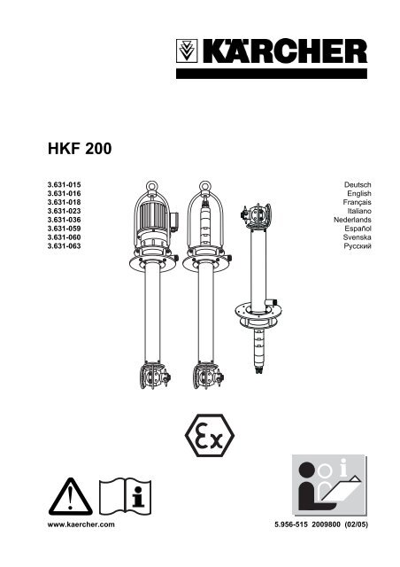
<strong>HKF</strong> <strong>200</strong><br />
3.631-015 Deutsch<br />
3.631-016 English<br />
3.631-018 Français<br />
3.631-023 Italiano<br />
3.631-036 Nederlands<br />
3.631-059 Español<br />
3.631-060 Svenska<br />
3.631-063 Русский<br />
!<br />
www.kaercher.com 5.956-515 <strong>200</strong>9800 (02/05)
Operating Instructions<br />
Please issue to the operator,<br />
ensure they read it before starting the initial operation and<br />
store it in a safe place for future use.<br />
About these operating instructions<br />
Read these instructions through carefully before<br />
the initial startup of the internal cleaner. Pay<br />
particular attention to all safety information.<br />
Store the instructions in a safe place for future<br />
use.<br />
These instructions are intended for<br />
the following target groups<br />
All users<br />
Users are instructed labourers, owner/operators<br />
and skilled persons.<br />
Skilled persons<br />
Skilled persons whose vocational training<br />
enables them to set up and startup equipment<br />
and systems.<br />
Environmental protection<br />
Please dispose of the packaging in an<br />
environmentally friendly way<br />
The packaging material can be recycled. Please<br />
do not throw the packaging in the domestic waste<br />
but place it in recycling containers.<br />
Please dispose of used units in an<br />
environmentally friendly way<br />
Used units contain valuable recyclable materials,<br />
which should be recycled. Batteries, oil and<br />
similar materials must not be allowed to get into<br />
the environment. Please therefore ensure that<br />
you use suitable collection systems to dispose<br />
of old units.<br />
Cleaning liquids<br />
Please do not allow them to get into the environment.<br />
Protect the soil and dispose of waste oil in<br />
an environmentally friendly way.<br />
Wastewater containing mineral oil<br />
Please do not allow it to get into the ground, bodies<br />
of water or the sewers.
<strong>HKF</strong> <strong>200</strong><br />
Contents<br />
English<br />
A. For your safety<br />
1. Safety information and tips<br />
2. Noise control<br />
3. Approved operators<br />
4. Personal protective equipment<br />
5. What to do in emergencies<br />
6. Proper intended use<br />
7. Special conditions in Ex-areas<br />
8. Schematic sketch of the area classification<br />
9. Area classification<br />
B. Function<br />
C. Technical Specifications<br />
1. Dimensional diagram <strong>HKF</strong> <strong>200</strong> E /<br />
<strong>HKF</strong> <strong>200</strong> C<br />
2. Dimensional diagram <strong>HKF</strong> <strong>200</strong> ET<br />
3. Dimensional diagram <strong>HKF</strong> <strong>200</strong> C2<br />
4. Dimensional diagram <strong>HKF</strong> <strong>200</strong> P<br />
5. Dimensional diagram <strong>HKF</strong> <strong>200</strong> PT<br />
6. Dimensional diagram <strong>HKF</strong> <strong>200</strong> PU<br />
7. Installation example <strong>HKF</strong> <strong>200</strong> PU<br />
8. Technical specifications<br />
<strong>HKF</strong> <strong>200</strong> E / ET / P<br />
9. Technical specifications<br />
<strong>HKF</strong> <strong>200</strong> PT / PU / C / C2<br />
10. Cleaning liquids<br />
11. List of materials<br />
12. Nozzle selection<br />
D. Operation<br />
1. Preparing for the initial startup<br />
2. Initial operation switch ON<br />
3. Shut-down procedure switch OFF<br />
E. Maintenance<br />
1. Maintenance instructions<br />
2. Maintenance intervals<br />
F. Troubleshooting<br />
1. Fault information<br />
2. Locating faults<br />
G. Accessories<br />
H. Guarantee<br />
I. Declaration of conformity<br />
5.956-515
A. For Your Safety<br />
English <strong>HKF</strong> <strong>200</strong><br />
1. Safety Information and Tips<br />
The following symbols are used in these operating<br />
instructions:<br />
! Danger!<br />
Denotes a direct, pending hazard. Failure to observe<br />
this information can cause fatal or severe<br />
injuries.<br />
Caution!<br />
Denotes a possibly hazardous situation. Failure<br />
to observe this information can lead to slight injuries<br />
or damage to property.<br />
i Important!<br />
Denotes user tips and important information.<br />
Incorrect operation or misuse can cause dangers<br />
for the operator and other persons due to:<br />
high pressure,<br />
high electric voltages (for electrical drive<br />
units with 230 or 400 V),<br />
Cleaning agents or used cleaning liquid,<br />
hot parts of the system, if hot cleaning liquids<br />
are used,<br />
Explosion danger.<br />
Please ensure you read the following before<br />
operating the system for the first time to avoid<br />
incorrect operations and hazards<br />
All safety information in the attached brochure<br />
"Safety information for high-pressure cleaning<br />
systems" No. 5.951-949,<br />
These operating instructions,<br />
The respective national regulatory legislation,<br />
The safety information enclosed with the cleaning<br />
agents used (usually on the packaging<br />
label).<br />
To avoid hazards due to incorrect operation, the<br />
system must only be operated by persons who<br />
have been instructed in its use,<br />
have proven their operating skills,<br />
have been deployed to use the machine.<br />
The operating instructions must be accessible<br />
to each user.<br />
! Danger!<br />
There is a risk of injuries or possible risk to health<br />
due to:<br />
the drive unit of the internal cleaner (crushing<br />
hazard). Only start up the drive unit of the internal<br />
cleaner in closed containers.<br />
The cleaner gives off a high-pressure spray,<br />
therefore only start up the internal cleaner in<br />
closed containers,<br />
Residual materials in containers, which are<br />
cleaned or from the cleaning liquid used.<br />
Therefore follow the prescribed protective<br />
measures,<br />
Falling internal cleaner at a low submersion<br />
depth. In this case you should additionally<br />
secure the internal cleaner,<br />
Falling containers, therefore additionally secure<br />
the container and internal cleaner,<br />
Hot hoses and hot frame when using hot cleaning<br />
liquids.<br />
When running the machine with hot cleaning<br />
liquids, do not touch the frame and supply<br />
line and wear appropriate protective clothing.<br />
Accidental startup after interrupting the<br />
mains voltage. Switch off the internal cleaner<br />
and high-pressure pump drive units in case<br />
of any faults.<br />
A1<br />
5.956-515
<strong>HKF</strong> <strong>200</strong><br />
A. For Your Safety<br />
English<br />
5. What to do in Emergencies<br />
Risk of explosion and fire when using corresponding<br />
cleaning agents and residual materials<br />
in containers. In these cases contact<br />
Kärcher to find out how these cleaning agents<br />
are to be used.<br />
Caution!<br />
In order to prevent damage to the spray head,<br />
ensure that it is freely positioned in the container.<br />
The spray head must never bump against<br />
the container wall.<br />
2. Noise Control<br />
The sound level of the internal cleaner with<br />
compressed air motor and without a silencer is<br />
max. 83 dB(A), see "Technical specifications". If<br />
parts which amplify sound (e.g. large metal plates,<br />
metal containers) are sprayed, a risk from<br />
noise can occur. In this case ear protection must<br />
be worn.<br />
3. Approved Operators<br />
Approved operators are persons who are 18<br />
and over and qualified to use this system (exceptions<br />
for trainees, see BGV D15 Art. 6).<br />
4. Personal Protective Equipment<br />
Depending on the concentration of and health<br />
hazard caused by the cleaning liquid used, wear<br />
liquid repellent protective clothing,<br />
protective goggles or face protection,<br />
impermeable gloves,<br />
impermeable footwear.<br />
Switch off the separate high-pressure pump,<br />
Switch off the drive unit of the internal cleaner,<br />
and at the same time<br />
– if the drive unit is electrical unplug it or<br />
switch off the power supply<br />
– if the drive unit is run on compressed air<br />
shut off the compressed air supply<br />
Shut off the cleaning liquid supply.<br />
6. Proper, Intended Use<br />
HFK <strong>200</strong> internal cleaners are spraying devices<br />
for cleaning barrels, containers and tank trucks.<br />
The cleaning head of the <strong>HKF</strong> <strong>200</strong> E / ET / C /<br />
P / PT is placed in the container through an opening<br />
with a diameter of at least <strong>200</strong> mm.<br />
<strong>HKF</strong> <strong>200</strong> ET / PT = min. 140 mm<br />
<strong>HKF</strong> <strong>200</strong> C2 = min. 300 mm<br />
The <strong>HKF</strong> <strong>200</strong> PU is intended for stationary operation.<br />
To this end it must be installed vertically<br />
upright, tightly fitting in a "dome" with flange.<br />
The containers to be cleaned are placed over<br />
the internal cleaner. (See the dimensional diagram<br />
and installation example <strong>HKF</strong> <strong>200</strong> PU for<br />
an illustration of the installation). A separate<br />
high-pressure pump is connected to the internal<br />
cleaner by a high-pressure hose.<br />
i Important!<br />
A list of approved cleaning liquids is given in<br />
Chapter C. Technical Specifications.<br />
It is not proper, intended use<br />
outside closed containers,<br />
with higher pressures and higher temperatures<br />
than those given in the "Technical Specifications".<br />
5.956-515<br />
A2
A. For Your Safety<br />
English <strong>HKF</strong> <strong>200</strong><br />
7. Special Conditions in the Ex-Area<br />
1. The internal cleaner may only be used in Area<br />
0 of containers, if the containers do not exceed<br />
3m diameter in size with a standard container<br />
height or a comparable container size.<br />
2. The cleaning liquid must not contain more<br />
than 1% by weight of undissolved solids.<br />
3. The internal cleaner must be electrostatically<br />
grounded.<br />
4. The cleaning liquid pump may only be run if it<br />
is filled with liquid.<br />
5. The nominal pressure of the pump must not<br />
exceed 50 bar for use with solvents.<br />
6 The pump's flow rate must not exceed 50 l/min<br />
when used with solvents.<br />
7. The compressed air motor or the electrical<br />
gear motor may only be run if the cleaning liquid<br />
is fed to the internal cleaner.<br />
8. The speed in rpm of the spraying head must<br />
not exceed 40 1/min.<br />
9. The operating temperature of the cleaning liquid<br />
must not exceed 95 °C if water with cleaning<br />
agents added is used.<br />
10. The operating temperature of the cleaning liquids<br />
must not exceed 20° C where solvents,<br />
lyes (alkaline solutions) and acids are used.<br />
11. The internal cleaner is to be inspected after<br />
a reasonable operating time to ensure it has a<br />
perfect condition and function (including<br />
checking that the drive motor is concentrically<br />
located relative to the gland part, and checking<br />
bearing bushes and drive seals for wear or<br />
leaks). Repair if necessary.<br />
12. The internal cleaner may only be operated<br />
with cleaning liquids and used in media if the<br />
materials it is made from have adequate resistance<br />
against these.<br />
13. Cleaning liquids, which contain combustible<br />
solvent fractions must correspond to the temperature<br />
classes IIA and IIB. Solvents in the temperature<br />
class IIC must not be sprayed.<br />
14. The internal cleaner must not be permanently<br />
placed in Area 0, only while the container<br />
is being cleaned. The operating regulations applicable<br />
within the scope of the BetrSichV (operating<br />
safety regulations) and other national regulations<br />
are to be complied with. It must be taken<br />
into consideration that the connection between<br />
the container and internal cleaner placed<br />
in the container does not have a flame arrester.<br />
15. Hoses must be electrostatically conductive<br />
(resistance R < 1 MÙ)<br />
16. Only cleaning liquids with a conductivity<br />
G > 1000 pS/m may be used.<br />
17. All parts in contact with the media are to be<br />
connected to the earth connection system.<br />
A3<br />
5.956-515
<strong>HKF</strong> <strong>200</strong><br />
A. For Your Safety<br />
English<br />
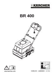
8. Schematic Sketch of the Area Classification<br />
Telescopic jib<br />
Area 1<br />
Winch for telescopic jib<br />
Winch for lifting and lowering<br />
the spraying head<br />
High-pressure spray head<br />
Slewing equipment<br />
Area 0/20<br />
Rotating<br />
spray head<br />
Area 1<br />
Clear<br />
medium<br />
Circulation<br />
medium<br />
Electrically conductive<br />
hose<br />
Circulation container with<br />
filter equipment<br />
- push-in strainer<br />
- suction basket (strainer)<br />
- fine filter<br />
5.956-515<br />
A4
A. For Your Safety<br />
English <strong>HKF</strong> <strong>200</strong><br />
9. Area Classification<br />
In the BetrSichV and EN 1127-1, hazardous<br />
(potentially explosive) areas are classified in<br />
areas according to the frequency and duration<br />
of the occurrence of hazardous, potentially atmospheres.<br />
It is the responsibility of the owner/operator<br />
to defined these areas.<br />
Information on area classification can be found<br />
in the BetrSichV, EN 1127-1, BGR 104 - Ex-Guidelines<br />
of BG Chemie and in DIN EN 60 079-10.<br />
Area 0<br />
is an area in which a hazardous, potentially explosive<br />
atmosphere exists constantly, frequently<br />
or for long periods of time as a mixture of air<br />
and combustible gases, vapours or mists and<br />
sprays.<br />
Area 20<br />
is an area in which a hazardous, potentially explosive<br />
atmosphere in the form of a cloud of<br />
combustible dust contained in the air exists constantly,<br />
frequently or for long periods of time.<br />
Area 21<br />
is an area in which a hazardous, potentially explosive<br />
atmosphere in the form of a cloud of<br />
combustible dust contained in the air can occasionally<br />
form during standard operation.<br />
Area 22<br />
is an area in which a hazardous, potentially explosive<br />
atmosphere in the form of a cloud of<br />
combustible dust contained in the air does not<br />
form during standard operation or only for a<br />
short time.<br />
Area 1<br />
is an area in which a hazardous, potentially explosive<br />
atmosphere consisting of a mixture of<br />
air and combustible gases, vapours or mists<br />
and sprays can occasionally form during standard<br />
operation.<br />
Area 2<br />
is an area in which a hazardous, potentially explosive<br />
atmosphere consisting of a mixture of<br />
air and combustible gases, vapours or mists<br />
and sprays does not normally occur during standard<br />
operation or only for a short time.<br />
A5<br />
5.956-515
<strong>HKF</strong> <strong>200</strong><br />
B. Function<br />
English<br />
Function<br />
The internal cleaner consists of a drive parts,<br />
the Carrier pipe and the cleaning head.<br />
The nozzles in the cleaning head rotate about<br />
two axes and therefore cover all areas of the<br />
container.<br />
An electrical or compressed air motor rotates<br />
the cleaning head. The speed in rpm is therefore<br />
independent of the pressure and quantity of<br />
cleaning liquid. In electrical drive units the<br />
speed is either constant or can be adjusted between<br />
two stages, where pneumatic drives are<br />
used the speed can be adjusted via the compressed<br />
air.<br />
5.956-515<br />
B1
C. Technical Data<br />
English <strong>HKF</strong> <strong>200</strong><br />
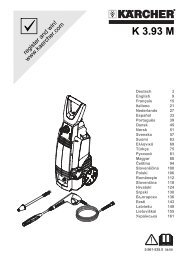
1. Dimensional Diagram <strong>HKF</strong> <strong>200</strong> E / <strong>HKF</strong> <strong>200</strong> C<br />
Cable entry for round cable<br />
min. Ø 10mm 4x1,5mm²<br />
Ø 30<br />
Hanging bracket<br />
Order-No. 4.034-126<br />
Hole pattern of the<br />
mounting flange<br />
Ø 250<br />
Ø 9<br />
Ø 180<br />
Ø 225<br />
565<br />
615<br />
120°<br />
3x120°<br />
Delivery connection M22x1.5<br />
Area 1<br />
Category 2 respectively 3<br />
Area 0/20<br />
Category 1<br />
Hole circle Ø225<br />
Flange Ø250<br />
Prescribed direction<br />
of rotation<br />
Standard length 800<br />
300 - 1500 special design<br />
X= Minimum inlet Ø180<br />
XX= Rotational Ø<strong>200</strong><br />
x<br />
xx<br />
C1<br />
5.956-515
<strong>HKF</strong> <strong>200</strong><br />
C. Technical Data<br />
English<br />
2. Dimensional Diagram <strong>HKF</strong> <strong>200</strong> ET<br />
Cable entry for round cable<br />
min. Ø 10 mm, 4x1.5 mm²<br />
Ø30<br />
Hanging bracket<br />
Order-No. 4.034-126<br />
Hole pattern of the mounting flange<br />
Delivery connection M 22x1.5<br />
Area 1<br />
Category 2 respectively 3<br />
Area 0/20<br />
Category 1<br />
Hole circle Ø 225<br />
Flange Ø 250<br />
Prescribed direction of rotation<br />
Standard length 500<br />
X = Minimum inlet Ø 140<br />
XX = Rotational Ø 142<br />
5.956-515<br />
C2
C. Technical Data<br />
English <strong>HKF</strong> <strong>200</strong><br />
3. Dimensional Diagram <strong>HKF</strong> <strong>200</strong> C2<br />
Cable entry for round cable<br />
min. Ø 10mm 4x1,5mm²<br />
Ø 30<br />
Hanging bracket<br />
Order No. 4.034-126<br />
Hole pattern of the<br />
mounting flange<br />
Ø 250<br />
Ø 9<br />
Ø 180<br />
Ø 225<br />
565<br />
615<br />
120°<br />
3x120°<br />
Delivery connection M22x1.5<br />
Area 1<br />
Category 2 respectively 3<br />
Area 0/20<br />
Category 1<br />
Hole circle Ø225<br />
Flange Ø250<br />
2 special nozzles,<br />
Nozzles can be<br />
switched over manually<br />
Prescribed direction<br />
of rotation<br />
Standard length 800<br />
300 - 1500 special design<br />
2 nozzles<br />
X= Minimum inlet Ø300<br />
XX= Rotational Ø320<br />
x<br />
xx<br />
C3<br />
5.956-515
Ø 225<br />
Ø 9<br />
<strong>HKF</strong> <strong>200</strong><br />
C. Technical Data<br />
English<br />
4. Dimensional Diagram <strong>HKF</strong> <strong>200</strong> P<br />
Hole pattern of the mounting flange<br />
Ø 250<br />
Ø30<br />
Ø 180<br />
120°<br />
3x120°<br />
290<br />
540<br />
Area 1<br />
Category 2 respectively 3<br />
Delivery connection M22x1.5<br />
Area 0/20<br />
Category 1<br />
EXH<br />
1<br />
2<br />
Air outlet glands<br />
(2 hoses DN 6,<br />
at least 1.5mm)<br />
Hole circle Ø225<br />
Flange Ø250<br />
Air requirement 300l/min<br />
at 5 bar<br />
Prescribed direction<br />
of rotation<br />
Standard length 800 (P) / 500 (PT)<br />
300 - 1500 special design (P)<br />
Air inlet glands<br />
(1 hose DN 6)<br />
X= Minimum inlet Ø180<br />
XX= Rotational Ø<strong>200</strong><br />
x<br />
xx<br />
5.956-515<br />
C4
C. Technical Data<br />
English <strong>HKF</strong> <strong>200</strong><br />
5. Dimensional Diagram <strong>HKF</strong> <strong>200</strong> PT<br />
Hole pattern of the mounting flange<br />
Hanging bracket<br />
Order-No. 4.034-016<br />
Area 1<br />
Category 2 respectively 3<br />
Delivery connection<br />
M 22x1.5<br />
Area 0/20<br />
Category 1<br />
Flange Ø 250<br />
”X”<br />
Air outlet glands<br />
(2 hoses DN 6)<br />
Hole circle Ø 225<br />
Prescribed direction of rotation<br />
Air requirement 300 l/min at 5 bar<br />
Standard length 500<br />
300-1500 special design<br />
Air inlet glands (1 hose DN 6)<br />
X = Minimum inlet Ø 140<br />
XX = Rotational Ø 142<br />
C5<br />
5.956-515
<strong>HKF</strong> <strong>200</strong><br />
C. Technical Data<br />
English<br />
6. Dimensional Diagram <strong>HKF</strong> <strong>200</strong> PU<br />
22,5°<br />
Ø16<br />
22,5°<br />
Ø20<br />
6x60°<br />
60°<br />
x<br />
20°<br />
Ø9<br />
xx<br />
Ø160<br />
Ø225<br />
Ø250<br />
Compressed air 1/4"-Ø8<br />
Air requirement<br />
300l/min at 5 bar<br />
Exhaust air 3/8"-Ø12<br />
Delivery connection<br />
M22x1.5<br />
300<br />
Area 0/20<br />
Category 1<br />
28<br />
665<br />
Area 1<br />
Category 2 respectively 3<br />
min. 400<br />
300<br />
(65)<br />
X= Minimum inlet Ø180<br />
XX= Rotational Ø<strong>200</strong><br />
Ø250<br />
5.956-515<br />
C6
C. Technical Data<br />
English <strong>HKF</strong> <strong>200</strong><br />
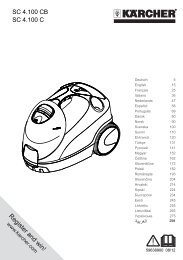
7. Installation Example <strong>HKF</strong> <strong>200</strong> PU<br />
o I N<br />
Ex<br />
Maintenance unit<br />
Compressed air filter<br />
Compressed air<br />
4-7 bar 300 l/h<br />
1/2"<br />
Exhaust air<br />
1/4"<br />
3/8"<br />
Holding device<br />
(Holding device with safety<br />
switch = option)<br />
<strong>HKF</strong> <strong>200</strong> PU<br />
Grating<br />
Compact circulation tank<br />
LxBxH=2700x1500x650 mm<br />
Push-in strainer<br />
SHD- R 3000 LM<br />
50 l/min-50 bar 6,8 kW<br />
Option<br />
Filter monitoring<br />
P MIN PMAX P W<br />
M<br />
Wire plate filter<br />
Exhaust air<br />
Ø100<br />
Suction filter<br />
slewable<br />
Clear rinsing<br />
agent supply<br />
customer-supplied<br />
C7<br />
5.956-515
<strong>HKF</strong> <strong>200</strong><br />
C. Technical Data<br />
English<br />
8. Technical Specifications<br />
Units<br />
<strong>HKF</strong> <strong>200</strong> E<br />
(3x400V)<br />
<strong>HKF</strong> <strong>200</strong> E<br />
(3x42V)<br />
<strong>HKF</strong> <strong>200</strong> ET <strong>HKF</strong> <strong>200</strong> P<br />
Order No. 3.631-015 3.631-018 3.631-063 3.631-016<br />
Throughput (MAX) l/h 10 000 10 000 10 000 10 000<br />
Max. flow rate for use<br />
with solvent<br />
Max. temperature for water<br />
with cleaning agents<br />
Max. temperature for<br />
solvents, lyes, acids<br />
l/h<br />
°C<br />
°C<br />
3000 3000 3000 3000<br />
95 95 95 95<br />
20 20 20 20<br />
Max. operating pressure bar <strong>200</strong> <strong>200</strong> <strong>200</strong> <strong>200</strong><br />
Max. operating pressure<br />
for use with solvents<br />
bar<br />
50 50 50 50<br />
Voltage V 230/400 42 (D) 230/400 –<br />
Type of current 3~ 3~ 3~ –<br />
Frequency Hz 50 50 50 –<br />
Rated power consumption W 120 120 120 –<br />
Compressed air<br />
bar<br />
l/min<br />
–<br />
–<br />
Functional speed drive 1/min 18,5 18,5 18,5 10–20<br />
Sound level<br />
(EN 60704-1)<br />
High-pressure connection DN 15<br />
M22x1.5<br />
–<br />
–<br />
–<br />
–<br />
4–7<br />
500<br />
dB(A) 70 70 70 83<br />
without<br />
silencer<br />
DN 15<br />
M22x1.5<br />
DN 15<br />
M22x1.5<br />
DN 15<br />
M22x1.5<br />
Min. container opening mm Ø <strong>200</strong> Ø <strong>200</strong> Ø 140 Ø <strong>200</strong><br />
Length incl. bracket up to<br />
middle of nozzle<br />
mm 1415 1415 1115 1220<br />
Standard immersed depth mm 800 800 500 800<br />
Weight kg 40 40 38 30<br />
Ambient conditions<br />
temperature<br />
Type of protection<br />
°C +2....+40 +2....+40 +2....+40 +2....+40<br />
II 1/2 G c T4 II 1/3 D c 120 °C<br />
5.956-515<br />
C8
C. Technical Data<br />
English <strong>HKF</strong> <strong>200</strong><br />
9. Technical Specifications<br />
Units <strong>HKF</strong> <strong>200</strong> PT <strong>HKF</strong> <strong>200</strong><br />
PU<br />
<strong>HKF</strong> <strong>200</strong> C<br />
<strong>HKF</strong> <strong>200</strong> C2<br />
Order No. 3.631-036 3.631-023 3.631-059 3.631-060<br />
Throughput (MAX) l/h 10 000 10 000 10 000 10 000<br />
Max. flow rate for use<br />
with solvent<br />
Max. temperature for water<br />
with cleaning agents<br />
Max. temperature for<br />
solvents, lyes, acids<br />
l/h<br />
°C<br />
°C<br />
3000 3000 3000 3000<br />
95<br />
95 95 95<br />
20 20 20 20<br />
Max. operating pressure bar <strong>200</strong> <strong>200</strong> <strong>200</strong> <strong>200</strong><br />
Max. operating pressure for<br />
use with solvents<br />
bar<br />
50 50 50 50<br />
Voltage V – – 400 400<br />
Type of current – – 3~ 3~<br />
Frequency Hz – – 50 50<br />
Rated power consumption W – – 300 300<br />
Compressed air<br />
bar<br />
l/min<br />
4–7<br />
500<br />
4–7<br />
594<br />
Functional speed drive 1/min 10–20 10–20 10/20 10/20<br />
Sound level<br />
(EN 60704-1)<br />
dB(A) 83<br />
without<br />
silencer<br />
High-pressure connection DN 15<br />
M22x1.5<br />
83<br />
without<br />
silencer<br />
DN 15<br />
M22x1.5<br />
–<br />
–<br />
–<br />
–<br />
70 70<br />
DN 15<br />
M22x1.5<br />
DN 15<br />
M22x1.5<br />
Min. container opening mm Ø 140 Ø <strong>200</strong> Ø <strong>200</strong> Ø 300<br />
Length incl. bracket up to<br />
middle of nozzle<br />
mm 920 700 1415 1415<br />
Standard immersed depth mm 500 300 800 800<br />
Weight kg 28 28 45 45<br />
Ambient conditions -<br />
temperature<br />
Type of protection<br />
°C +2....+40 +2....+40 +2....+40 +2....+40<br />
II 1/2 G c T4 II 1/3 D c 120 °C<br />
C9<br />
5.956-515
<strong>HKF</strong> <strong>200</strong><br />
C. Technical Data<br />
English<br />
10. Cleaning Liquids<br />
Solvents<br />
Acids<br />
! Danger!<br />
The relevant special safety regulations must be<br />
complied with when using the unit with solvents<br />
or in hazardous, potentially explosive areas!<br />
Maximum pressure for use with solvents: 50 bar<br />
Maximum flow rate for use with solvents: 50 l/min<br />
Caution!<br />
When using solvents, the sealing materials have<br />
a reduced durability, therefore you must always<br />
rinse the unit immediately after use! Please contact<br />
Kärcher if you have any questions!<br />
1. Hydrocarbons<br />
e.g.: Petroleum<br />
2. Aromatic compounds (solvents)<br />
e.g.: benzene, toluene<br />
3. Ketones<br />
e.g.: MEK (methyl ethyl ketones), acetone<br />
4. Esters<br />
e.g.: butyl acetate, methyl acetate<br />
5. Glycols<br />
e.g.: butyl glycol<br />
6. Mixed solvents<br />
e.g.: butyl acetate 85, isobutyl acetate 85<br />
(85 = 85% butyl acetate + 15 % n-butanol)<br />
7. Regenerated substances, distillates made<br />
from various solvents, which have already<br />
been used for cleaning or similar purposes.<br />
Lyes<br />
Caution!<br />
Increased material erosion if hydrochloric and<br />
sulphuric acid are used, therefore rinse/neutralise<br />
immediately after use! Reduced durability if<br />
impure acids are used! Please contact Kärcher<br />
if you have any questions!<br />
1. Water with acidic cleaning agent<br />
(max. 0 - 1%)<br />
e.g.: Kärcher RM25 cleaning agent<br />
2. Acids (max. temperature +20 °C)<br />
Nitric acid max. 10%<br />
Ethanoic acid max. 10%<br />
Formic acid max. 10%<br />
Phosphoric acid max. 10%<br />
Citric acid max. 10%<br />
Sulphuric acid max. 0.5%<br />
Hydrochloric acid max. 0.5%<br />
Water<br />
1. Water<br />
2. Demineralised water<br />
Other cleaning liquids<br />
When using other cleaning liquids use the materials<br />
list to check the durability!<br />
These cleaning liquids may only be used after<br />
they have been released by Kärcher!<br />
1. Water with alkali cleaning agent<br />
(max. 0 - 2%)<br />
e.g.: Kärcher RM31 cleaning agent<br />
2. Hydrated caustic soda max. 10%,<br />
without hypochlorite fractions<br />
3. Potassium hydroxide max. 10%,<br />
without hypochlorite fractions<br />
5.956-515<br />
C10
C. Technical Data<br />
English <strong>HKF</strong> <strong>200</strong><br />
11. Materials List<br />
Item Description Order No. Material Number Media<br />
contact<br />
1 Protective part 4.394-009 5.000-506 metal plate<br />
1.4301<br />
5.114-077 ring<br />
1.4541<br />
1 X<br />
2 Protective part 4.394-011 1.4301 1 X<br />
3 Circular lamination 5.005-174 1.4541 3 X<br />
4 Housing 5.060-085 1.4305 1 X<br />
5 Housing 5.060-114 1.4305 1 X<br />
6 Shaft 5.100-043 1.4305 1 X<br />
7 Shaft 5.100-044 1.4305 1 X<br />
8 Washer 5.115-122 Teflon - bronze 2 X<br />
9 Flange 5.122-059 1.4305 2 X<br />
10 Flange 5.122-068 1.4305 1 X<br />
11 Pin 5.314-037 1.4541 2 X<br />
12 Bevel gear 5.354-003 1.4305 1 X<br />
13 Bevel gear 5.354-004 1.4305 1 X<br />
14 Coupler 5.471-031 1.4305 1 X<br />
15 Ring 5.570-039 CuSn8F55 4 X<br />
16 Cheese head screw M5x12 6.304-011 1.4571 20 X<br />
17 Cheese head screw M5x16 6.304-012 1.4571 10 X<br />
18 Cheese head screw M8x16 6.304-013 1.4571 1 X<br />
19 Cheese head screw M5x30 6.304-112 A4-70 1<br />
20 Lock washer 8.4 6.343-125 Nirosta X7 1 X<br />
21 O-ring 23.47 x 2.62 6.362-219 EPDM 1 X<br />
22 O-ring 18 x 2,5 6.362-431 FPM 1 X<br />
23 O-ring 17.96 x 2,62 6.363-154 FPM 1 X<br />
24 Lip seal D26 x D38 6.365-423 PTFE 4 X<br />
25 Hexagonal screw M8x16 7.304-538 A4-70 1 X<br />
26 Hexagonal nut M5 7.311-203 A4-70 2 X<br />
27 Cap nut M5 7.311-385 A1-50 4 X<br />
28 Sealing ring 22 7.362-011 Cu 1 X<br />
29 VS screw 7.382-251 1.4571 1 X<br />
30 Shaft 4.100-229 5.100-492 shaft 1.4305<br />
VS screw 1.4571<br />
1 X<br />
C11<br />
5.956-515
<strong>HKF</strong> <strong>200</strong><br />
C. Technical Data<br />
English<br />
12. Nozzle Selection<br />
Throughout<br />
l/h<br />
Pressure<br />
bar<br />
Number<br />
of<br />
nozzles<br />
Nozzle size<br />
mm<br />
Order No.<br />
3000 50 4 1.8 4.765-007 o o – – –<br />
3000 50 2 2.4 5.765-006 x x – – –<br />
3000 60 4 1.65 5.765-082 o o – – –<br />
3000 50 2 2.7 4.765-006 x x – – –<br />
3000 50 1 3.8 4.765-008 o o – – –<br />
3000 80 2 2.5 5.765-018 o o – – –<br />
3800 50 2 2.9 5.765-025 o o – – –<br />
3800 80 2 2.7 4.765-006 x x – – –<br />
6000 50 2 3.8 4.765-008 o o – – –<br />
6000 80 2 3.5 5.768-075 o o o – –<br />
6000 80 1 5.0 of inquiry o o o – –<br />
8000 80 2 3.8 4.765-008 – – x – –<br />
3800 80 2 2,7 6.415-862 – – – x x<br />
<strong>HKF</strong> <strong>200</strong> E<br />
<strong>HKF</strong> <strong>200</strong> P<br />
<strong>HKF</strong> <strong>200</strong> C<br />
<strong>HKF</strong> <strong>200</strong> PT<br />
<strong>HKF</strong> <strong>200</strong> ET<br />
Remarks<br />
The size of the nozzle is imprinted on the key<br />
area of the nozzles.<br />
o = possible<br />
x = fitted as a standard<br />
5.956-515<br />
C12
D. Operation<br />
English <strong>HKF</strong> <strong>200</strong><br />
1. Preparation for the initial startup<br />
Electrical drive unit<br />
! Danger!<br />
Risk of fatal injuries due to high electrical voltage.<br />
The required electrical installations must<br />
only be carried out by a qualified electrician.<br />
The plug socket used must:<br />
be fused with a residual current operated circuit-breaker<br />
with a tripping current of 30 mA,<br />
close to the workplace so that the mains plug<br />
can be quickly removed in case of emergency.<br />
Where the mains connection is fixed, a lockable<br />
master switch must be installed for complete<br />
disconnection from the electricity system.<br />
Electrical drive units 42 V and 400 V<br />
Connect wiring (4-cored) to the three-phase<br />
a.c. motor,<br />
connect the motor cable to the power supply<br />
via a lockable master switch,<br />
switch on spray head and check the direction<br />
of rotation.<br />
The spray head must rotate in the following direction<br />
when in operation:<br />
Pneumatic drive<br />
Caution!<br />
Install a maintenance unit in the compressed air<br />
feed (Kärcher Order No. 6.610-020) in order to<br />
avoid damage to the pneumatic drive due to<br />
condensation and poor lubrication.<br />
The maintenance unit must be designed for<br />
An air throughput of 500 l/min,<br />
Pressures up to 7 Bar.<br />
The maintenance unit consists of:<br />
Water separator,<br />
Pressure regulator with manometer,<br />
Proportional lubricator.<br />
Fill proportional lubricator with suitable lubricating<br />
oil. To do this unscrew the storage tank and<br />
pour in the lubricating oil (See the "Maintenance"<br />
section for oil type and grade).<br />
D1<br />
5.956-515
<strong>HKF</strong> <strong>200</strong><br />
D. Operation<br />
English<br />
Fit the compressed air hoses to the<br />
compressed air motor<br />
i Important!<br />
If the silencers are too small, the exhaust air<br />
backpressure created causes the pneumatic<br />
drive to run unsafely. Install hoses at the exhaust<br />
air openings.<br />
2. Switch on for initial operation<br />
! Danger!<br />
Risk of injuries due to possibly hot high-pressure<br />
jet given off by the unit. Therefore<br />
only start up the internal cleaner in containers<br />
closed on all sides,<br />
only place the internal cleaner into the container<br />
or change to another container if the<br />
separate high-pressure pump and the unit's<br />
own drive are switched off.<br />
Place the internal cleaner on the container<br />
and secure if necessary,<br />
Connect the high-pressure pump with the internal<br />
cleaner using a high-pressure hose,<br />
Switch on the drive unit of the internal cleaner,<br />
to do this<br />
– Switch on the power supply to the<br />
electrical drive unit<br />
– Open the compressed air supply to the<br />
pneumatic drive<br />
Open the cleaning liquid inlet,<br />
Switch on the separate high-pressure pump.<br />
Install fresh air hose<br />
Fresh air hose size DN 6,<br />
Install exhaust air hoses to connection No. 2.<br />
Install exhaust air hose<br />
Hose length 1-2 m,<br />
Hose size for exhaust air DN 6,<br />
To connection No. 1 and EXH.<br />
5.956-515<br />
D2
D. Operation<br />
English <strong>HKF</strong> <strong>200</strong><br />
3. Shut-down procedure-switch OFF<br />
i Important!<br />
Before starting the shut-down procedure rinse<br />
through the internal cleaner for 30 seconds without<br />
adding cleaning agents. This way you prevent<br />
incrustations and conglutination, and<br />
therefore premature wear of the seals.<br />
Switch off the separate high-pressure pump,<br />
Shut off the cleaning liquid supply,<br />
Switch off the drive unit of the internal cleaner<br />
by<br />
– removing the mains plug of the electrical<br />
drive units or by switching off the power<br />
supply,<br />
– shutting off the compressed air supply to<br />
the pneumatic drive,<br />
Remove the internal cleaner from the container.<br />
D3<br />
5.956-515
<strong>HKF</strong> <strong>200</strong><br />
E. Maintenance<br />
English<br />
1. Maintenance instructions<br />
Regular maintenance is the basis for a safe<br />
operating system (see table on page E2).<br />
Only use original parts or parts recommended<br />
by the manufacturer, such as<br />
Spare and wearing parts,<br />
Accessory parts,<br />
Resources, fuel, etc,<br />
Cleaning agents.<br />
! Danger!<br />
Risk of accidents when working on the system.<br />
When carrying out any work<br />
disconnect the high-pressure pump at the<br />
master switch and secure,<br />
shutoff the cleaning liquid supply,<br />
switch off the drive unit des internal cleaner,<br />
to do this<br />
– remove the mains plug of electrical drive<br />
units or switch off the power supply<br />
– shutoff the compressed air supply to the<br />
pneumatic drive<br />
Who may carry out maintenance works?<br />
Operator<br />
Works marked "owner/operator" may only be<br />
carried out by instructed persons who can<br />
safely operate and service high-pressure<br />
equipment and systems.<br />
Service agreement<br />
To guarantee reliable operation of the system,<br />
we recommend that you take out a service<br />
agreement. Please contact the Kärcher customer<br />
service responsible for you.<br />
5.956-515<br />
E1
E. Maintenance<br />
English <strong>HKF</strong> <strong>200</strong><br />
2. Maintenance intervals<br />
Time Activity Execution Who<br />
Weekly or<br />
every 40<br />
operating<br />
hours<br />
Monthly or<br />
every 160<br />
operating<br />
hours<br />
Check<br />
compressed<br />
air<br />
maintenance<br />
unit<br />
Check that all<br />
screws are<br />
tight<br />
Caution!<br />
Hazard due to compressed air. Shut off the compressed<br />
air before carrying out any maintenance<br />
work and allow any compressed air in the system<br />
to flow out at the maintenance unit first.<br />
Drain off the water in the water separator by<br />
– opening the water drain plug<br />
– drain water off<br />
– close water drain plug<br />
Fill the proportional lubricator with suitable<br />
lubricating oil. To do this unscrew the storage tank<br />
and pour in the lubricating oil. See table below for<br />
lubricating oil types to be used.<br />
Check that all screws are tight.<br />
Operator<br />
Operator<br />
Lubricating oil for compressed air<br />
maintenance unit<br />
(for Order No. 3.631-016, 3.631-036)<br />
Festo spezial<br />
Aral Vitam GF 32<br />
Esso Nuto H 32<br />
Mobil DTE 24<br />
BP Energol HLP 32<br />
E2<br />
5.956-515
<strong>HKF</strong> <strong>200</strong><br />
F. Troubleshooting<br />
English<br />
1. Fault information<br />
! Danger!<br />
Risk of accidents when working on the System.<br />
Before carrying out any work<br />
disconnect the high-pressure pump at the<br />
master switch and secure,<br />
shutoff the cleaning liquid supply,<br />
switch off the drive unit des internal cleaner,<br />
to do this<br />
– remove the mains plug of electrical drive<br />
units or switch off the power supply<br />
– shutoff the compressed air supply to the<br />
pneumatic drive<br />
Who may correct faults?<br />
Operator<br />
Works marked "owner/operator" may only be<br />
carried out by instructed persons who can<br />
safely operate and service high-pressure<br />
equipment and systems.<br />
Qualified electricians<br />
Work marked "qualified electrician" may only<br />
be carried out by persons who have successfully<br />
completed an electrical engineering<br />
vocational course.<br />
Customer service<br />
Works marked "customer service" may only<br />
be carried out by the fitters of Kärcher's customer<br />
service.<br />
5.956-515<br />
F1
F. Troubleshooting<br />
English <strong>HKF</strong> <strong>200</strong><br />
2. Locating faults<br />
Fault Possible cause Solution By whom<br />
Motor wont rotate No voltage supply to motor Check fuses and cables Electrician<br />
Motor rotates but<br />
not the spray head<br />
Spray head rotates<br />
jerkily<br />
Motor protection switch has<br />
tripped<br />
Residual current operated<br />
circuit-breaker has tripped<br />
No compressed air or<br />
pressure too low<br />
Air feed line bent<br />
Mechanical defect in<br />
- Coupling parts<br />
- Drive shaft<br />
- Gearing<br />
Worn thrust rings lead to<br />
increased bevel gear<br />
clearance<br />
Gear teeth of bevel gears<br />
worn<br />
Remove cause of the<br />
overload, reset motor<br />
protection switch<br />
Remove cause and reset<br />
the residual current<br />
operated circuit-breaker<br />
Check compressed air<br />
Check compressed air<br />
hoses<br />
Check parts, replace<br />
defective parts<br />
Replace thrust ring<br />
Replace bevel gears<br />
Electrician<br />
Electrician<br />
Operator<br />
Operator<br />
Customer service<br />
Customer service<br />
Customer service<br />
Uneven cleaning jet Spray nozzles blocked Clean spray nozzles Operator<br />
Spray nozzles damaged Replace spray nozzles Operator<br />
F2<br />
5.956-515
<strong>HKF</strong> <strong>200</strong><br />
G. Accessories<br />
English<br />
Accessories<br />
The HFK <strong>200</strong> internal cleaner can be supplemented with the following accessories:<br />
Description<br />
Order No.<br />
Compressed air maintenance unit (only for compressed air operation) 6.610-020<br />
Compressed air filter with automatic condensate drain<br />
(only for compressed air operation)<br />
6.414-154<br />
Bracket (VA) HFK <strong>200</strong> P/PT 4.034-016<br />
Bracket (VA) HFK <strong>200</strong> E/ET/C/C2 4.034-126<br />
Domed cover (VA) Ø 560 mm 4.210-022<br />
High pressure hose, NW 13 – 1.5 m* 1) 6.389-126<br />
High pressure hose, NW 13 – 10 m* 1) 4.440-173<br />
Coupling NW 13* 4.403-002<br />
90° threaded connection NW 13* 4.408-023<br />
Compressed air hose (sold by the metre) 6.388-192<br />
Exhaust air silencer with oil separator<br />
auf Anfrage<br />
* Possible for max. 4000 l/h cleaning liquid flow rate. Please inform Kärcher if higher cleaning liquid<br />
flow rates are required.<br />
1) Hoses for use with solvents must be electrostatically conductive!<br />
5.956-515<br />
G1
H. Guarantee<br />
English <strong>HKF</strong> <strong>200</strong><br />
Guarantee<br />
The guarantee terms and conditions issued by<br />
our sales company in each country apply.<br />
In case of guarantee claims, please contact<br />
your dealer or your nearest authorised customer<br />
service agent.<br />
H1<br />
5.956-515
<strong>HKF</strong> <strong>200</strong><br />
I. Declaration of Conformity<br />
English<br />
EC Declaration of Conformity<br />
We herewith declare that the design and type of<br />
machine named in the following as well as the<br />
model marketed by us complies with the relevant<br />
fundamental health and safety requirements<br />
of the EC Directives.<br />
This declaration becomes invalid if modifications<br />
are made to the machine which have not<br />
been previously agreed with us.<br />
Product: Internal cleaner<br />
Type: <strong>HKF</strong> <strong>200</strong> P, <strong>HKF</strong> <strong>200</strong> PU,<br />
<strong>HKF</strong> <strong>200</strong> PT<br />
Relevant EC Directives:<br />
EC Machine Directive (98/37/EC)<br />
EC ATEX Directive (94/9/EC)<br />
Harmonised standards used:<br />
DIN EN 292 - 1<br />
DIN EN 292 - 2<br />
DIN EN 13463 - 1: <strong>200</strong>2<br />
prEN 13463 - 5: <strong>200</strong>2<br />
EN 1127 - 1: 1997<br />
Alfred Kärcher GmbH & Co. KG<br />
Cleaning Systems<br />
Alfred-Kärcher-Str. 28-40<br />
P.O. Box 160<br />
D-71349 Winnenden<br />
Phone: ++ 49 71 95 14-0<br />
Fax: ++ 49 71 95 14-22 12<br />
5.957-454 (06/03)<br />
Alfred Kärcher Kommanditgesellschaft.<br />
Registered office: Winnenden.<br />
Register court: Waiblingen, HRA 169.<br />
Personally liable shareholder:<br />
Kärcher Reinigungstechnik GmbH.<br />
Registered office: Winnenden, 2404 Waiblingen<br />
register court, HRB<br />
Managing Directors: Dr. Bernhard Graf,<br />
Hartmut Jenner, Georg Metz<br />
National standards used: -<br />
No. of nominated test institute: 0123<br />
Test report No. 70043569<br />
Designation:<br />
Ex II 1/2 G c T4<br />
Ex II 1/3 D c 120 °C<br />
Internal measures ensure that serial production<br />
units always comply with the requirements of<br />
the current EC Directives and the standards<br />
used.<br />
The undersigned act on behalf of and with power<br />
of attorney issued by the management.<br />
S. Reiser H. Jenner<br />
5.956-515<br />
I1
I. Declaration of Conformity<br />
English <strong>HKF</strong> <strong>200</strong><br />
EC Declaration of Conformity<br />
We herewith declare that the design and type of<br />
machine named in the following as well as the<br />
model marketed by us complies with the relevant<br />
fundamental health and safety requirements<br />
of the EC Directives.<br />
This declaration becomes invalid if modifications<br />
are made to the machine which have not<br />
been previously agreed with us.<br />
Product: Internal cleaner<br />
Type: <strong>HKF</strong> <strong>200</strong> E, <strong>HKF</strong> <strong>200</strong> ET,<br />
<strong>HKF</strong> <strong>200</strong> C, <strong>HKF</strong> <strong>200</strong> C2<br />
Relevant EC Directives:<br />
EC Machine Directive (98/37/EC)<br />
EC ATEX Directive (94/9/EC)<br />
Harmonised standards used:<br />
DIN EN 292 - 1<br />
DIN EN 292 - 2<br />
DIN EN 60 204 - 1<br />
DIN EN 13463 - 1: <strong>200</strong>2<br />
prEN 13463 - 5: <strong>200</strong>2<br />
EN 1127 - 1: 1997<br />
Alfred Kärcher GmbH & Co. KG<br />
Cleaning Systems<br />
Alfred-Kärcher-Str. 28-40<br />
P.O. Box 160<br />
D-71349 Winnenden<br />
Phone: ++ 49 71 95 14-0<br />
Fax: ++ 49 71 95 14-22 12<br />
5.957-735 (06/03)<br />
Alfred Kärcher Kommanditgesellschaft.<br />
Registered office: Winnenden.<br />
Register court: Waiblingen, HRA 169.<br />
Personally liable shareholder:<br />
Kärcher Reinigungstechnik GmbH.<br />
Registered office: Winnenden, 2404 Waiblingen<br />
register court, HRB<br />
Managing Directors: Dr. Bernhard Graf,<br />
Hartmut Jenner, Georg Metz<br />
National standards used: -<br />
No. of nominated test institute: 0123<br />
Test report No. 70043569<br />
Designation:<br />
Ex II 1/2 G c T4<br />
Ex II 1/3 D c 120 °C<br />
Internal measures ensure that serial production<br />
units always comply with the requirements of<br />
the current EC Directives and the standards<br />
used.<br />
The undersigned act on behalf of and with power<br />
of attorney issued by the management.<br />
S. Reiser H. Jenner<br />
I2<br />
5.956-515
<strong>HKF</strong> <strong>200</strong><br />
English<br />
5.956-515