Druckschrift 99810560, Combiners and Filters for FM ... - Kathrein
Druckschrift 99810560, Combiners and Filters for FM ... - Kathrein
Druckschrift 99810560, Combiners and Filters for FM ... - Kathrein

Create successful ePaper yourself
Turn your PDF publications into a flip-book with our unique Google optimized e-Paper software.
BCA<br />
<strong>Combiners</strong> <strong>and</strong> <strong>Filters</strong> <strong>for</strong><br />
<strong>FM</strong> Broadcast <strong>and</strong> TV Systems<br />
ABRIDGEMENT
Photo on title page: <strong>FM</strong> Multipattern Combiner, 3x 10 kW<br />
Catalogue Issue 02/2007<br />
All data published in previous catalog issues hereby becomes invalid.<br />
We reserve the right to make alterations in accordance with the requirements of our customers,<br />
there<strong>for</strong>e <strong>for</strong> binding datas please check valid datasheets!<br />
Please note:<br />
As a result of more stringent legal regulations<br />
<strong>and</strong> judgements regarding product liability, we are<br />
obliged to point out certain risks that may arise<br />
when products are used under extraordinary<br />
operating conditions.<br />
Extraordinary operating conditions, such as exceptional<br />
dynamic stress (e.g. strain caused by oscillating<br />
support structures), may result in decline in technical<br />
per<strong>for</strong>mance.<br />
Installation teams must be properly qualified <strong>and</strong><br />
also be familiar with the relevant national safety<br />
regulations.<br />
“Quality leads the way”<br />
As the world’s oldest <strong>and</strong> largest antenna manufacturer, we live up to claim “Quality<br />
leads the way” on a daily basis. One of the fundamental principies is to always be on<br />
the lookout <strong>for</strong> the best solution <strong>for</strong> our customers.<br />
Our quality assurance system <strong>and</strong> our environmental management system apply to the<br />
entire company <strong>and</strong> are certified by TÜV according to EN ISO 9001 <strong>and</strong> EN ISO 14001.<br />
Internet: http://www.kathrein.de<br />
KATHREIN-Werke KG . Phone +49 80 31 184-0 . Fax +49 80 31 184-495<br />
Anton-<strong>Kathrein</strong>-Straße 1 – 3 . P.O. Box 10 04 44 . D-83004 Rosenheim . Germany
Contents<br />
Page<br />
Who we are 4<br />
B<strong>and</strong> II (<strong>FM</strong>)<br />
87.5 – 108 MHz 5 – 13<br />
B<strong>and</strong> III (VHF)<br />
174 – 230 MHz 14 – 17<br />
B<strong>and</strong> IV/V (UHF)<br />
470 – 860 MHz 18 – 19<br />
Further Components 20 – 21<br />
Customized Design 22 – 23<br />
Technical Annex 24 – 29<br />
3
Who we are<br />
<strong>Kathrein</strong>-Werke KG, founded in 1919 in Rosenheim<br />
(Germany), is an international enterprise,<br />
active in antenna <strong>and</strong> communications technology.<br />
Since the early 1960’s <strong>Kathrein</strong>-Werke KG has<br />
been supplying professional combiner systems<br />
of all sizes to broadcasters in every part of the<br />
world – from Canada to China <strong>and</strong> from Norway to<br />
South Africa.<br />
Right from the start <strong>Kathrein</strong>-Werke KG has<br />
maintained a high level of engineering capability.<br />
Today there is a team of antenna <strong>and</strong> mechanical<br />
engineers dealing exclusively with broadcast<br />
transmitting systems.<br />
Customers are welcome to take advantage of<br />
the technical expertise available from <strong>Kathrein</strong>-<br />
Werke KG <strong>and</strong> to discuss their specific requirements.<br />
If your needs cannot met with our st<strong>and</strong>ard<br />
components we are prepared to develop<br />
customized solutions <strong>for</strong> you.<br />
<strong>Kathrein</strong>-Werke KG quality management system<br />
is certified in accordance with DIN EN ISO 9001.<br />
This certification includes manufacturing<br />
operations as well as design processes.<br />
As a result of the introduction of the Environment<br />
Management System according DIN EN ISO<br />
14001 environmental protection is beeing<br />
systematically integrated into the corporation<br />
entire process chain.<br />
4
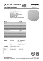
B<strong>and</strong>-pass Filter<br />
87.5 ... 108 MHz, 100 W<br />
B<strong>and</strong>-pass filter can be used<br />
– <strong>for</strong> improving the input selectivity of receivers <strong>and</strong><br />
amplifiers<br />
– <strong>for</strong> increasing the isolation of transmitters where<br />
respective antennas are close together<br />
– <strong>for</strong> suppressing noise side b<strong>and</strong>s <strong>and</strong> intermodulation<br />
products<br />
– as a component in the construction of combiners<br />
Design <strong>and</strong> Construction<br />
The b<strong>and</strong>-pass filter is made of three capacitively<br />
coupled resonators. The operating frequency, the<br />
coupling between the resonators <strong>and</strong> also the input <strong>and</strong><br />
output couplings are adjustable.<br />
The b<strong>and</strong>-pass filter is convection-cooled, no ventilators<br />
are required.<br />
The b<strong>and</strong>-pass filter must be tuned to the operating<br />
channel. Tuning may be done at our factory or can be<br />
carried out on site.<br />
Clear tuning instructions <strong>and</strong> also any special tools<br />
necessary are part of the delivery extent.<br />
719 118 <strong>FM</strong> B<strong>and</strong>-pass filter, 100 W<br />
Technical Data<br />
Type No. 719 118<br />
Frequency range<br />
87.5 ... 108 MHz<br />
Insertion loss (1<br />
< 0.7 dB<br />
VSWR<br />
< 1.1 (at pass b<strong>and</strong>)<br />
Impedance<br />
50 Ω<br />
Input power<br />
max. 100 W<br />
Temperature range –20 °C ... +50 °C<br />
Connectors<br />
7-16 female<br />
Material<br />
Aluminium (outer conductor)<br />
Brass, silver-plated (inner conductor)<br />
Weight<br />
12 kg<br />
Dimensions (l x w x h)<br />
460 mm x 312 mm x 100 mm<br />
Packing size (l x w x h)<br />
550 mm x 360 mm x 160 mm<br />
(1 Insertion loss value apply to st<strong>and</strong>ard tuning with 3-dB b<strong>and</strong>width<br />
of about 1.250 kHz.<br />
Attenuation/dB<br />
Attenuation/dB<br />
0<br />
10<br />
20<br />
30<br />
40<br />
50<br />
-5 -4 -3 -2 -1 f 0 +1 +2 +3 +4 +5<br />
Frequency/MHz<br />
0<br />
1<br />
2<br />
3<br />
4<br />
5<br />
-1.0<br />
-0.8 -0.6 -0.4 -0.2 f 0 +0.2 +0.4 +0.6 +0.8 +1.0<br />
Frequency/MHz<br />
5
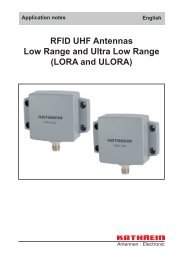
B<strong>and</strong>-pass Filter<br />
87.5 ... 108 MHz, 3 kW<br />
B<strong>and</strong>-pass filter can be used<br />
– <strong>for</strong> improving the input selectivity of receivers <strong>and</strong><br />
amplifiers<br />
– <strong>for</strong> increasing the isolation of transmitters whose<br />
respective antennas are close together<br />
– <strong>for</strong> suppressing noise side b<strong>and</strong>s <strong>and</strong> intermodulation<br />
products<br />
– as a component in the construction of combiners<br />
Design <strong>and</strong> Construction<br />
The b<strong>and</strong>-pass filter is made of three capacitively<br />
coupled, temperature stabilised resonators. The<br />
operating frequency, the coupling between the<br />
resonators <strong>and</strong> also the input <strong>and</strong> output couplings are<br />
adjustable.<br />
Any heat produced is dissipated into the surroundings<br />
via heat sinks. The b<strong>and</strong>-pass filter is convectioncooled,<br />
so no ventilators are required.<br />
The b<strong>and</strong>-pass filter must be tuned to the operating<br />
channel. Tuning may be done at our factory or can be<br />
carried out on site.<br />
Clear tuning instructions <strong>and</strong> also any special tools<br />
necessary are part of the delivery extent.<br />
728 726 <strong>FM</strong> B<strong>and</strong>-pass filter, 3 kW<br />
Technical Data<br />
Type No. 728 726<br />
Frequency range<br />
87.5 ... 108 MHz<br />
Insertion loss (1<br />
< 0.25 ... 0.5 dB<br />
VSWR<br />
< 1.1 (at pass b<strong>and</strong>)<br />
Impedance<br />
50 Ω<br />
Input power<br />
max. 3 kW<br />
Temperature range –20 °C ... +50 °C<br />
Connectors<br />
7/8″ EIA-flange<br />
Material<br />
Aluminium (outer conductor)<br />
Brass, silver-plated (inner conductor)<br />
Colour<br />
RAL 7032 (grey)<br />
Weight<br />
55 kg<br />
Dimensions (l x w x h)<br />
680 mm x 220 mm x 1320 mm<br />
Packing size (l x w x h)<br />
720 mm x 300 mm x 1500 mm<br />
(1 Insertion loss value with st<strong>and</strong>ard tuning will be approx. 0.35 dB;<br />
refering 3-dB b<strong>and</strong>width is 900 kHz.<br />
Attenuation/dB<br />
Attenuation/dB<br />
0<br />
10<br />
20<br />
30<br />
40<br />
50<br />
-5 -4 -3 -2 -1 f 0 +1 +2 +3 +4 +5<br />
Frequency/MHz<br />
0<br />
1<br />
2<br />
3<br />
4<br />
5<br />
-1.0<br />
-0.8 -0.6 -0.4 -0.2 f 0 +0.2 +0.4 +0.6 +0.8 +1.0<br />
Frequency/MHz<br />
6
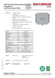
B<strong>and</strong>-pass Filter<br />
87.5 ... 108 MHz, 5 kW<br />
B<strong>and</strong>-pass filter can be used<br />
– <strong>for</strong> improving the input selectivity of receivers <strong>and</strong><br />
amplifiers<br />
– <strong>for</strong> increasing the isolation of transmitters whose<br />
respective antennas are close together<br />
– <strong>for</strong> suppressing noise side b<strong>and</strong>s <strong>and</strong> intermodulation<br />
products<br />
– as a component in the construction of combiners<br />
Design <strong>and</strong> Construction<br />
The b<strong>and</strong>-pass filter is made of three capacitively<br />
coupled, temperature stabilised resonators. The<br />
operating frequency, the coupling between the<br />
resonators <strong>and</strong> also the input <strong>and</strong> output couplings are<br />
adjustable.<br />
Any heat produced is dissipated into the surroundings<br />
via heat sinks. The b<strong>and</strong>-pass filter is convectioncooled,<br />
so no ventilators are required.<br />
The b<strong>and</strong>-pass filter must be tuned to the operating<br />
channel. Tuning may be done at our factory or can be<br />
carried out on site.<br />
Clear tuning instructions <strong>and</strong> also any special tools<br />
necessary are part of the delivery extent.<br />
730 150 <strong>FM</strong> B<strong>and</strong>-pass filter, 5 kW<br />
Technical Data<br />
Type No. 730 150<br />
Frequency range<br />
87.5 ... 108 MHz<br />
Insertion loss (1<br />
< 0.25 ... 0.4 dB<br />
VSWR<br />
< 1.1 (at pass b<strong>and</strong>)<br />
Impedance<br />
50 Ω<br />
Input power<br />
max. 5 kW<br />
Temperature range –20 °C ... +50 °C<br />
Connectors<br />
1 5/8″ EIA-flange<br />
Material<br />
Aluminium (outer conductor)<br />
Brass, silver-plated (inner conductor)<br />
Colour<br />
RAL 7032 (grey)<br />
Weight<br />
100 kg<br />
Dimensions (l x w x h)<br />
975 mm x 285 mm x 1260 mm<br />
Packing size (l x w x h)<br />
1100 mm x 470 mm x 1450 mm<br />
(1 Insertion loss value with st<strong>and</strong>ard tuning will be approx. 0.30 dB;<br />
reference 3-dB b<strong>and</strong>width is 800 kHz.<br />
Attenuation/dB<br />
Attenuation/dB<br />
0<br />
10<br />
20<br />
30<br />
40<br />
50<br />
-5 -4 -3 -2 -1 f 0 +1 +2 +3 +4 +5<br />
Frequency/MHz<br />
0<br />
1<br />
2<br />
3<br />
4<br />
5<br />
-1.0<br />
-0.8 -0.6 -0.4 -0.2 f 0 +0.2 +0.4 +0.6 +0.8 +1.0<br />
Frequency/MHz<br />
7
Starpoint Combiner<br />
87.5 ... 108 MHz, 100 W<br />
General<br />
Starpoint combiners enable several transmitters or<br />
receivers to be connected to one common output. This<br />
arrangement provides a cost-efficient solution while<br />
retaining the advantages of b<strong>and</strong>-pass filter usage.<br />
Design <strong>and</strong> Construction<br />
This starpoint combiners consist of one 3-pole b<strong>and</strong>pass<br />
filter per channel. The inputs of the filters are narrowb<strong>and</strong>.<br />
The outputs are connected via<br />
pre-defined cable lengths to a common starpoint. This<br />
starpoint then <strong>for</strong>ms the output of the combiner.<br />
The starpoint combiners may be extended by adding<br />
further b<strong>and</strong>-pass filters <strong>and</strong> by exchanging the starpoint.<br />
The combiners are maintenance-free <strong>and</strong> are thus<br />
especially safe to operate.<br />
The b<strong>and</strong>-pass filters must be tuned to the operating<br />
channel. Tuning may be done at our factory or can be<br />
carried out on site.<br />
Clear tuning instructions <strong>and</strong> also any special tools<br />
necessary are supplied along with the combiner.<br />
793 196 <strong>FM</strong> Starpoint combiner, 4x 100 W<br />
Output<br />
Starpoint<br />
CH 1<br />
Input 1<br />
CH 2<br />
Input 2<br />
CH 3<br />
Input 3<br />
CH 4<br />
Input 4<br />
Technical Data<br />
Type No. Inputs Insertion Connectors Weight Height (2 Packing size<br />
loss (1 Input / Output [mm]<br />
793 192 2 < 0.9 dB 7-16 female 31 kg 8 HU 650 x 590 x 450<br />
793 194 3 < 0.9 dB 7-16 female 43 kg 8 HU 650 x 590 x 450<br />
793 196 4 < 1.0 dB 7-16 female 55 kg 12 HU 650 x 590 x 630<br />
Frequency range<br />
87.5 ... 108 MHz<br />
Channel spacing<br />
> 2 MHz<br />
Isolation<br />
> 30 dB<br />
VSWR<br />
< 1.1 (at pass b<strong>and</strong>)<br />
Impedance<br />
50 Ω<br />
Input power<br />
max. 100 W (per input)<br />
Temperature range –20 °C ... +50 °C<br />
Material<br />
Aluminium (outer conductor)<br />
Brass, silver-plated (inner conductor)<br />
Colour (front plate)<br />
RAL 7032 (grey)<br />
Dimensions<br />
19″ drawer (depth 550 mm)<br />
(1 Insertion loss value refers to a 3-dB b<strong>and</strong>width of 1.250 kHz. Minimum 3-dB b<strong>and</strong>width is 1000 kHz.<br />
(2 One HU (height unit) is equivalent to 44.45 mm<br />
8
Starpoint Combiner<br />
87.5 ... 108 MHz, 3 kW<br />
General<br />
Starpoint combiners enable several transmitters or<br />
receivers to be connected to one common output. This<br />
arrangement provides a cost efficient solution while<br />
retaining the advantages of b<strong>and</strong>-pass filter usage.<br />
Design <strong>and</strong> Construction<br />
This starpoint combiners consist of one temperature<br />
stabilised 3-pole b<strong>and</strong>-pass filter per channel. The<br />
inputs of the filters are narrowb<strong>and</strong>. The outputs are<br />
connected via pre-defined rigid-lines onto a common<br />
starpoint. This starpoint then <strong>for</strong>ms the output of the<br />
combiner.<br />
The starpoint combiners may be extended by adding<br />
further b<strong>and</strong>-pass filters <strong>and</strong> by exchanging the starpoint.<br />
Any heat produced is dissipated into the surroundings<br />
via heat sinks. The starpoint combiner is convectioncooled,<br />
so no ventilators are required.<br />
The b<strong>and</strong>-pass filters must be tuned to the operating<br />
channel. Tuning may be done at our factory or can be<br />
carried out on site.<br />
Clear tuning instructions <strong>and</strong> also any special tools<br />
necessary are supplied along with the combiner.<br />
728 868 <strong>FM</strong> Starpoint combiner, 2x 3 kW<br />
Output<br />
Starpoint<br />
Technical Data<br />
CH 1<br />
Input 1<br />
CH 2<br />
Input 2<br />
Type No. Inputs Insertion Connectors Weight Dimensions Packing size<br />
loss (1 Input / Output (l x w x h) [mm] [mm]<br />
728 868 2 < 0.5 dB 7/8″ EIA / 1 5/8″ EIA 110 kg 790 x 482 x 1320 1010 x 610 x 1400<br />
730 040 3 < 0.6 dB 7/8″ EIA / 1 5/8″ EIA 180 kg 1553 x 482 x 1320 1x 1010 x 610 x 1400<br />
1x 1010 x 315 x 1400<br />
730 041 4 < 0.7 dB 7/8″ EIA / 1 5/8″ EIA 250 kg 1553 x 482 x 1320 2x 1010 x 610 x 1400<br />
Frequency range<br />
87.5 ... 108 MHz<br />
Channel spacing<br />
> 1.5 MHz<br />
Isolation<br />
> 30 dB<br />
VSWR<br />
< 1.1 (at pass b<strong>and</strong>)<br />
Impedance<br />
50 Ω<br />
Input power<br />
max. 3 kW (per input)<br />
Temperature range –20 °C ... +50 °C<br />
Material<br />
Aluminium (outer conductor)<br />
Brass, sliver plated (inner conductor)<br />
Colour<br />
RAL 7032 (grey)<br />
(1 Insertion loss value refers to a 3-dB b<strong>and</strong>width of 900 kHz. Minimum 3-dB b<strong>and</strong>width is 600 kHz.<br />
9
Starpoint Combiner<br />
87.5 ... 108 MHz, 5 kW<br />
General<br />
Starpoint combiners enable several transmitters or<br />
receivers to be connected to one common output. This<br />
arrangement provides a cost efficient solution while<br />
retaining the advantages of b<strong>and</strong>-pass filter usage.<br />
Design <strong>and</strong> Construction<br />
This starpoint combiners consist of one temperature<br />
stabilised 3-pole b<strong>and</strong>-pass filter per channel. The<br />
inputs of the filters are narrowb<strong>and</strong>. The outputs are<br />
connected via pre-defined rigid-lines onto a common<br />
starpoint. This starpoint then <strong>for</strong>ms the output of the<br />
combiner.<br />
The starpoint combiners may be extended by adding<br />
further b<strong>and</strong>-pass filters <strong>and</strong> by exchanging the starpoint.<br />
Any heat produced is dissipated into the surroundings<br />
via heat sinks. The starpoint combiner is convectioncooled,<br />
so no ventilators are required.<br />
The b<strong>and</strong>-pass filters must be tuned to the operating<br />
channel. Tuning may be done at our factory or can be<br />
carried out on site.<br />
Clear tuning instructions <strong>and</strong> also any special tools<br />
necessary are supplied along with the combiner.<br />
790 719 <strong>FM</strong> Starpoint combiner, 4x 5 kW<br />
Output<br />
Starpoint<br />
CH 1<br />
Input 1<br />
CH 2<br />
Input 2<br />
CH 3<br />
Input 3<br />
CH 4<br />
Input 4<br />
Technical Data<br />
Type No. Inputs Insertion Connectors Weight Dimensions Packing size<br />
loss (1 Input / Output (l x w x h) [mm] [mm]<br />
790 717 2 < 0.4 dB 1 5/8″ EIA / 1 5/8″ EIA 220 kg 975 x 695 x 1275 1080 x 890 x 1500<br />
790 718 3 < 0.5 dB 1 5/8″ EIA / 3 1/8″ EIA 335 kg 2185 x 695 x 1260 2x 1080 x 890 x 1500<br />
1x 1080 x 470 x 1500<br />
790 719 4 < 0.6 dB 1 5/8″ EIA / 3 1/8″ EIA 450 kg 2185 x 695 x 1260 2x 1080 x 890 x 1500<br />
Frequency range<br />
87.5 ... 108 MHz<br />
Channel spacing<br />
> 1.5 MHz<br />
Isolation<br />
> 35 dB<br />
VSWR<br />
< 1.1 (at pass b<strong>and</strong>)<br />
Impedance<br />
50 Ω<br />
Input power<br />
max. 5 kW (per input)<br />
Temperature range –20 °C ... +50 °C<br />
Material<br />
Aluminium (outer conductor)<br />
Brass, silver-plated (inner conductor)<br />
Colour<br />
RAL 7032 (grey)<br />
(1 Insertion loss value refers to a 3-dB b<strong>and</strong>width of 800 kHz. Minimum 3-dB b<strong>and</strong>width is 600 kHz.<br />
10
Directional Filter Combiner<br />
87.5 ... 108 MHz, 200 W<br />
General<br />
Directional filter combiners enable several transmitters<br />
to be connected to one common output.<br />
The design offers an exp<strong>and</strong>able system which is<br />
constructed in a modular <strong>for</strong>m. The configuration<br />
provides the best frequency response <strong>and</strong> optimum<br />
isolation between the inputs.<br />
Design <strong>and</strong> Construction<br />
This combiner consists of two 3-pole b<strong>and</strong>-pass filters,<br />
two 3-dB couplers <strong>and</strong> a balancing load.<br />
One input is narrowb<strong>and</strong> (NB) in accordance with the<br />
frequency response of the b<strong>and</strong>-pass filters. The<br />
second input is broadb<strong>and</strong> (BB) within the operating<br />
frequency range of the 3-dB coupler.<br />
The directional filter combiner may be extended by<br />
adding further combiners – directional filter combiners<br />
as well as starpoint combiners.<br />
Any heat produced is dissipated into the surroundings.<br />
Thus the combiner is maintenance free <strong>and</strong> especially<br />
safe to operate.<br />
The b<strong>and</strong>-pass filters must be tuned to the operating<br />
channel. Tuning may be done at our factory or can be<br />
carried out on site.<br />
Clear tuning instructions <strong>and</strong> also any special tools<br />
necessary are supplied along with the combiner.<br />
790 277 <strong>FM</strong> Directional filter combiner, 200 W<br />
Technical Data<br />
Type No. 790 277<br />
Output<br />
Inputs Narrowb<strong>and</strong> input (NB) Broadb<strong>and</strong> input (BB)<br />
Frequency range 87.5 ... 108 MHz 87.5 – 108 MHz<br />
tuned to one channel free choice of channel<br />
Insertion loss (1 < 0.8 dB < 0.2 dB<br />
Input power 200 W 800 W<br />
Channel spacing<br />
> 1.5 MHz<br />
Isolation<br />
> 30 dB (NB to BB-input)<br />
> 50 dB (BB to NB-input)<br />
VSWR<br />
< 1.1 (at pass b<strong>and</strong>)<br />
< 1.25 (at stop b<strong>and</strong>)<br />
Impedance<br />
50 Ω<br />
Temperature range –20 °C ... +50 °C<br />
Connectors<br />
7-16 female<br />
Colour (front-plate)<br />
RAL 7032 (grey)<br />
Weight<br />
34 kg<br />
Dimensions<br />
19″ drawer<br />
(6 height units, depth 550 mm) (2<br />
CH 1<br />
Narrowb<strong>and</strong> input<br />
(NB)<br />
Load<br />
CH 2<br />
Broadb<strong>and</strong> input<br />
(BB)<br />
(1 Insertion loss <strong>and</strong> isolation values refer to the min. channel spacing of 1.5 MHz.<br />
(2 One HU (hight unit) refers to 44.45 mm.<br />
11
Directional Filter Combiner<br />
87.5 ... 108 MHz, 5 kW<br />
General<br />
The directional filter combiners enable several transmitters<br />
to be connected to one common output.<br />
The design offers an exp<strong>and</strong>able system which is<br />
constructed in a modular <strong>for</strong>m. The configuration<br />
provides the best frequency response <strong>and</strong> optimum<br />
isolation between the inputs.<br />
Design <strong>and</strong> Construction<br />
This combiner consists of two temperature stabilised<br />
3-pole b<strong>and</strong>-pass filters, two 3-dB couplers <strong>and</strong> a<br />
balancing load.<br />
One input is narrowb<strong>and</strong> (NB) in accordance with the<br />
frequency response of the b<strong>and</strong>-pass filters. The<br />
second input is broadb<strong>and</strong> (BB) within the operating<br />
frequency range of the 3-dB coupler.<br />
The directional filter combiner may be extended by<br />
adding further combiners – directional filter combiners<br />
as well as starpoint combiners.<br />
Any heat produced is dissipated into the surroundings<br />
via heat sinks. Thus the combiner is maintenance-free<br />
<strong>and</strong> especially safe to operate.<br />
The b<strong>and</strong>-pass filters must be tuned to the operating<br />
channel. Tuning may be done at our factory or can be<br />
carried out on site.<br />
Clear tuning instructions <strong>and</strong> also any special tools<br />
necessary are supplied along with the combiner.<br />
726 473 <strong>FM</strong> Directional filter combiner, 5 kW<br />
Technical Data<br />
Type No. 726 473<br />
Output<br />
Inputs Narrowb<strong>and</strong> input (NB) Broadb<strong>and</strong> input (BB)<br />
Frequency range 87.5 ... 108 MHz 87.5 – 108 MHz<br />
tuned to one channel free choice of channel<br />
Insertion loss (1 < 0.35 ... 0.5 dB < 0.2 dB<br />
Input power 5 kW 15 kW<br />
Channel spacing<br />
> 0.8 MHz<br />
Isolation<br />
> 30 dB (NB to BB-input)<br />
> 50 dB (BB to NB-input)<br />
VSWR<br />
< 1.1 (at pass b<strong>and</strong>)<br />
< 1.25 (at stop b<strong>and</strong>)<br />
Impedance<br />
50 Ω<br />
Temperature range –20 °C ... +50 °C<br />
Connectors<br />
7/8″ EIA-flange (NB-input)<br />
1 5/8″ EIA-flange (BB-input <strong>and</strong> Output)<br />
Colour<br />
RAL 7032 (grey)<br />
Weight<br />
140 kg<br />
Dimensions (l x w x h)<br />
850 mm x 560 mm x 1320 mm<br />
Packing size (l x w x h)<br />
1015 mm x 615 mm x 1400 mm<br />
CH 1<br />
Narrowb<strong>and</strong> input<br />
(NB)<br />
Load<br />
CH 2<br />
Broadb<strong>and</strong> input<br />
(BB)<br />
(1 Insertion loss <strong>and</strong> isolation values refer to the min. channel spacing of 0.8 MHz.<br />
12
Directional Filter Combiner<br />
87.5 ... 108 MHz, 10 kW<br />
General<br />
The directional filter combiners enable several transmitters<br />
to be connected to one common output.<br />
The design offers an exp<strong>and</strong>able system which is<br />
constructed in a modular <strong>for</strong>m. The configuration<br />
provides the best frequency response <strong>and</strong> optimum<br />
isolation between the inputs.<br />
Design <strong>and</strong> Construction<br />
This combiner consists of two temperature stabilised<br />
3-pole b<strong>and</strong>-pass filters, two 3-dB couplers <strong>and</strong> a<br />
balancing load.<br />
One input is narrowb<strong>and</strong> (NB) in accordance with the<br />
frequency response of the b<strong>and</strong>-pass filters. The<br />
second input is broadb<strong>and</strong> (BB) within the operating<br />
frequency range of the 3-dB coupler.<br />
The directional filter combiner may be extended by<br />
adding further combiners – directional filter combiners<br />
as well as starpoint combiners.<br />
Any heat produced is dissipated into the surroundings<br />
via heat sinks. Thus the combiner is maintenance free<br />
<strong>and</strong> especially safe to operate.<br />
The b<strong>and</strong>-pass filters must be tuned to the operating<br />
channel. Tuning may be done at our factory or can be<br />
carried out on site.<br />
Clear tuning instructions <strong>and</strong> also any special tools<br />
necessary are supplied along with the combiner.<br />
728 393 <strong>FM</strong> Directional filter combiner, 10 kW<br />
Technical Data<br />
Type No. 728 393<br />
Output<br />
Inputs Narrowb<strong>and</strong> input (NB) Broadb<strong>and</strong> input (BB)<br />
Frequency range 87.5 ... 108 MHz 87.5 ... 108 MHz<br />
tuned to one channel free choice of channel<br />
Insertion loss (1 < 0.3 ... 0.4 dB < 0.15 dB<br />
Input power 10 kW 50 kW<br />
Channel spacing<br />
> 0.8 MHz<br />
Isolation<br />
> 35 dB (NB to BB-input)<br />
> 55 dB (BB to NB-input)<br />
VSWR<br />
< 1.1 (at pass b<strong>and</strong>)<br />
< 1.25 (at stop b<strong>and</strong>)<br />
Impedance<br />
50 Ω<br />
Temperature range –20 °C ... +50 °C<br />
Connectors<br />
1 5/8″ EIA-flange (NB-input)<br />
3 1/8″ EIA-flange (BB-input <strong>and</strong> Output)<br />
Colour<br />
RAL 7032 (grey)<br />
Weight<br />
290 kg<br />
Dimensions (l x w x h)<br />
1150 mm x 695 mm x 1435 mm<br />
Packing size (l x w x h)<br />
1350 mm x 870 mm x 1620 mm<br />
CH 1<br />
Narrowb<strong>and</strong> input<br />
(NB)<br />
Load<br />
~<br />
~<br />
CH 2<br />
Broadb<strong>and</strong> input<br />
(BB)<br />
(1 Insertion loss <strong>and</strong> isolation values refer to the min. channel spacing of 0.8 MHz.<br />
13
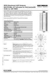
B<strong>and</strong>-pass Filter<br />
210 ... 230 MHz, DAB, 1 kW<br />
The b<strong>and</strong>-pass filter can be used<br />
– as output filter of DAB-transmitters<br />
– <strong>for</strong> appliances where high Q is requested to achiveve<br />
low insertion loss in addtion with high selectivity close<br />
to the pass-b<strong>and</strong><br />
– to achieve filter-mask criteria con<strong>for</strong>m to st<strong>and</strong>ard<br />
ETS-300401 – non critical mask<br />
– as a component in the construction of DAB-combiners<br />
Design <strong>and</strong> Construction<br />
The b<strong>and</strong>-pass filter is made of six inductively coupled<br />
resonators. The operating frequency, the coupling<br />
between the resonators <strong>and</strong> also the input <strong>and</strong> output<br />
couplings are adjustable.<br />
The b<strong>and</strong>-pass filter is convection-cooled, no ventilators<br />
are required.<br />
The b<strong>and</strong>-pass filter must be tuned to the operating<br />
channel. Tuning may be done at our factory or can be<br />
carried out on site.<br />
Clear tuning instructions <strong>and</strong> also any special tools<br />
necessary are part of the delivery extent.<br />
792 776 DAB B<strong>and</strong>-pass filter, 1 kW<br />
Technical Data<br />
Type No. 792 776<br />
Frequency range<br />
Insertion loss (1<br />
Selectivity<br />
VSWR<br />
Impedance<br />
Input power<br />
210 ... 230 MHz<br />
< 0.9 dB (at f 0 typ. 0.7 dB)<br />
< 1.1 dB (at edge frequencies)<br />
> 40 dB (at f 0 ± 1.768 MHz)<br />
> 60 dB (at f 0 ± 5 MHz)<br />
< 1.2 (at pass b<strong>and</strong>)<br />
50 Ω<br />
max. 1 kW<br />
Temperature range –20 °C ... +50 °C<br />
Connectors<br />
7-16 female<br />
Material<br />
Aluminium (outer conductor)<br />
Brass, silver-plated (inner conductor)<br />
Colour<br />
RAL 7032 (grey)<br />
Weight<br />
45 kg<br />
Dimensions (l x w x h)<br />
610 mm x 400 mm x 550 mm<br />
Packing size (l x w x h)<br />
800 mm x 600 mm x 1100 mm<br />
Attenuation/dB<br />
0<br />
20<br />
40<br />
60<br />
80<br />
100<br />
–5.0 –4.0 –3.0 –2.0 –1.0 +1.0 +2.0 +3.0 +4.0 +5.0<br />
f 0 /MHz<br />
Frequency/MHz<br />
(1 Insertion loss value apply to st<strong>and</strong>ard tuning with pass-b<strong>and</strong> width<br />
of 1.54 kHz.<br />
14
B<strong>and</strong>-pass Filter<br />
210 ... 230 MHz, DAB, 2 kW<br />
The b<strong>and</strong>-pass filter can be used<br />
– as output filter of DAB-transmitters<br />
– <strong>for</strong> appliances where high Q is requested to achiveve<br />
low insertion loss in addtion with high selectivity close<br />
to the pass-b<strong>and</strong><br />
– to achieve filter-mask criteria con<strong>for</strong>m to st<strong>and</strong>ard<br />
ETS-300401 – critical mask<br />
– as a component in the construction of DAB-combiners<br />
Design <strong>and</strong> Construction<br />
The b<strong>and</strong>-pass filter is made of eight inductively coupled<br />
resonators. The operating frequency, the coupling<br />
between the resonators <strong>and</strong> also the input <strong>and</strong> output<br />
couplings are adjustable.<br />
The b<strong>and</strong>-pass filter is convection-cooled, no ventilators<br />
are required.<br />
The b<strong>and</strong>-pass filter must be tuned to the operating<br />
channel. Tuning may be done at our factory or can be<br />
carried out on site.<br />
The b<strong>and</strong>-pass filter can be mounted in an 19″ rack.<br />
Clear tuning instructions <strong>and</strong> also any special tools<br />
necessary are part of the delivery extent.<br />
792 955 DAB B<strong>and</strong>-pass filter, 2 kW<br />
Also availble is a version with 1 5/8″ EIA-flanges.<br />
Max power h<strong>and</strong>ling then 3 kW.<br />
Technical Data<br />
Type No. 792 955<br />
Frequency range<br />
Insertion loss (1<br />
Selectivity<br />
VSWR<br />
Impedance<br />
Input power<br />
Temperature range<br />
Connectors<br />
Material<br />
Colour<br />
Weight<br />
Dimensions (l x w x h)<br />
Packing size (l x w x h)<br />
210 ... 230 MHz<br />
< 0.8 dB (at f 0 typ. 0.6 dB)<br />
< 1.5 dB (at edge frequencies)<br />
> 20 dB (at f 0 ± 0.968 MHz)<br />
> 55 dB (at f 0 ± 1.768 MHz)<br />
> 60 dB (at f 0 ± 5 MHz)<br />
< 1.2 (at pass b<strong>and</strong>)<br />
50 Ω<br />
max. 2 kW<br />
–20° C ... +50° C<br />
7-16 female<br />
Aluminium (outer conductor)<br />
Brass, sliver plated (inner conductor)<br />
RAL 7032 (grey)<br />
150 kg<br />
1.140 mm x 570 mm x 500 mm<br />
1.400 mm x 800 mm x 800 mm<br />
Attenuation/dB<br />
0<br />
20<br />
40<br />
60<br />
80<br />
100<br />
–5.0 –4.0 –3.0 –2.0 –1.0 +1.0 +2.0 +3.0 +4.0 +5.0<br />
f 0 /MHz<br />
Frequency/MHz<br />
(1 Insertion loss value apply to st<strong>and</strong>ard tuning with pass-b<strong>and</strong> width<br />
of 1.54 kHz.<br />
15
Stretchline Combiner<br />
174 ... 230 MHz, 200 W<br />
General<br />
Stretchline combiners enable several transmitters to be<br />
connected to one common output.<br />
The stretchline combiner offers a low cost solution with<br />
compact design. The configuration is ideal if the<br />
frequency spacing is not too close.<br />
Design <strong>and</strong> Construction<br />
This stretchline combiner consists of two 3-dB couplers,<br />
a commutating line <strong>and</strong> a balancing load.<br />
The inputs are narrowb<strong>and</strong> (NB) in accordance with the<br />
frequency response of the commutating line.<br />
The principle of operation refers to the length of the<br />
commutating line. The electrical characteristics of the<br />
3-dB couplers make the functioning possible. Isolation<br />
between the inputs is determined by the 3-dB couplers.<br />
The stretchline combiner may be extended by adding<br />
further directional filter combiners.<br />
The length of the commutating line has to be calculated<br />
with refer to the operating channels.<br />
714 624 VHF Stretchline combiner, 2x 200 W<br />
Channel 1<br />
Channel 2<br />
Attenuation/dB<br />
0<br />
1<br />
f 1 f 2<br />
Output<br />
3<br />
Load<br />
10<br />
20<br />
30<br />
CH 1<br />
Input 1<br />
CH 2<br />
Input 2<br />
174<br />
181<br />
188<br />
195<br />
202<br />
209<br />
216<br />
223<br />
230<br />
Frequency/MHz<br />
Technical Data<br />
Type No. Inputs Insertion Power Weigth Dimensions Packing size<br />
loss (1 (per input) [mm] [mm]<br />
714 624 2 < 0.5 dB 200 W 3.5 kg 450 x 350 x 90 540 x 460 x 180<br />
792 302 3 < 0.6 dB 200 W 4.0 kg 450 x 350 x 200 540 x 460 x 320<br />
Frequency range<br />
174 ... 230 MHz<br />
Channel spacing<br />
> 3 channels (2 CH between)<br />
Isolation<br />
> 30 dB<br />
VSWR<br />
< 1.06 (at pass b<strong>and</strong>)<br />
Impedance<br />
50 Ω<br />
Temperature range –20 °C ... +50 °C<br />
Connectors<br />
7-16 female<br />
Colour<br />
RAL 7032 (grey)<br />
(1 Insertion loss <strong>and</strong> isolation values refer to the minimum channel spacing.<br />
Given is the typical value. Insertion loss is depending on channel combination.<br />
16
Stretchline Combiner<br />
174 ... 230 MHz, 2 kW<br />
General<br />
Stretchline combiners enable several transmitters to<br />
be connected to one common output.<br />
The stretchline combiner offers a low cost solution<br />
with compact design. The configuration is ideal if the<br />
frequency spacing is not too close.<br />
Design <strong>and</strong> Construction<br />
This stretchline combiner consists of two 3-dB couplers,<br />
a commutating line <strong>and</strong> a balancing load.<br />
The inputs are narrowb<strong>and</strong> (NB) in accordance with the<br />
frequency response of the commutating line.<br />
The principle of operation refers to the length of the<br />
commutating line. The electrical characteristics of the<br />
3-dB couplers make the functioning possible. Isolation<br />
between the inputs is determined by the 3-dB couplers.<br />
The stretchline combiner may be extended by adding<br />
further directional filter combiners.<br />
The length of the commutating line has to be calculated<br />
with refer to the operating channels.<br />
792 462 VHF Stretchline combiner, 2x 2 kW<br />
Channel 1<br />
Channel 2<br />
f 1 f 2<br />
Attenuation/dB<br />
0<br />
1<br />
3<br />
Technical Data<br />
10<br />
Type No. / Order No. 792 714 462 624<br />
20<br />
Frequency range<br />
174 ... 230 MHz<br />
Inputs 2<br />
Channel spacing<br />
> 3 channels (2 CH between)<br />
Insertion loss (1<br />
< 0.4 dB<br />
Isolation<br />
> 30 dB<br />
VSWR<br />
< 1.06 (at pass b<strong>and</strong>)<br />
Impedance<br />
50 Ω<br />
Input power<br />
2 kW (per input)<br />
Temperature range –20 °C ... +50 °C<br />
Connectors<br />
7/8″ EIA-flange<br />
Colour<br />
RAL 7032 (grey)<br />
Weight<br />
85 kg<br />
Dimensions (l x w x h)<br />
1500 mm x 800 mm x 200 mm<br />
Packing size (l x w x h)<br />
1800 mm x 1000 mm x 500 mm<br />
(1 Insertion loss <strong>and</strong> isolation values refer to the minimum channel spacing.<br />
Given is the typical value. Insertion loss is depending on channel combination.<br />
30<br />
174<br />
181<br />
188<br />
Load<br />
195<br />
Output<br />
CH 1<br />
Input 1<br />
202<br />
209<br />
CH 2<br />
Input 2<br />
216<br />
223<br />
Frequency/MHz<br />
230<br />
17
Stretchline Combiner<br />
470 ... 860 MHz, 100 W<br />
General<br />
Stretchline combiners enable several transmitters to be<br />
connected to one common output.<br />
The stretchline combiner offer a low cost solution with<br />
compact design. The configuration is ideal if the<br />
frequency spacing is not too close.<br />
Design <strong>and</strong> Construction<br />
This stretchline combiner consists of two 3-dB couplers,<br />
a commutating line <strong>and</strong> a balancing load.<br />
The inputs are narrowb<strong>and</strong> (NB) in accordance with the<br />
frequency response of the commutating line.<br />
The principle of operation refers to the length of the<br />
commutating line. The electrical characteristics of the<br />
3-dB couplers make the functioning possible. Isolation<br />
between the inputs is determined by the 3-dB couplers.<br />
The stretchline combiner may be extended by adding<br />
further directional filter combiners.<br />
The length of the commutating line has to be calculated<br />
with refer to the operating channels.<br />
723 185 UHF Stretchline combiner, 2x 100 W<br />
f 1 f 2<br />
Output<br />
Attenuation/dB<br />
0<br />
1<br />
3<br />
Load<br />
10<br />
20<br />
30<br />
470 500<br />
550<br />
600<br />
650<br />
700 750 800<br />
Frequency/MHz<br />
850<br />
CH 1<br />
Input 1<br />
CH 2<br />
Input 2<br />
Technical Data<br />
Type No. Inputs Insertion Power Weigth Dimensions Packing size<br />
loss (1 (per input) [mm] [mm]<br />
723 185 2 < 0.5 dB 100 W 3 kg 700 x 400 x 50 900 x 600 x 100<br />
723 186 3 < 0.6 dB 100 W 5.5 kg 700 x 400 x 90 900 x 600 x 150<br />
Frequency range<br />
470 ... 860 MHz<br />
Channel spacing<br />
> 3 channels (2 CH between)<br />
Isolation<br />
> 30 dB<br />
VSWR<br />
< 1.1 (at pass b<strong>and</strong>)<br />
Impedance<br />
50 Ω<br />
Temperature range –20 °C ... +50 °C<br />
Connectors<br />
7-16 female<br />
Colour<br />
RAL 7032 (grey)<br />
(1 Insertion loss <strong>and</strong> isolation values refer to the minimum channel spacing.<br />
Given is the typical value. Insertion loss is depending on channel combination.<br />
18
Stretchline Combiner<br />
470 ... 860 MHz, 1 kW<br />
General<br />
Stretchline combiners enable several transmitters to be<br />
connected to one common output.<br />
The stretchline combiner offer a low cost solution with<br />
compact design. The configuration is ideal if the<br />
frequency spacing is not too close.<br />
Design <strong>and</strong> Construction<br />
This stretchline combiner consists of two 3-dB couplers,<br />
a commutating line <strong>and</strong> a balancing load.<br />
The inputs are narrowb<strong>and</strong> (NB) in accordance with the<br />
frequency response of the commutating line.<br />
The principle of operation refers to the length of the<br />
commutating line. The electrical characteristics of the<br />
3-dB couplers make the functioning possible. Isolation<br />
between the inputs is determined by the 3-dB couplers.<br />
The stretchline combiner may be extended by adding<br />
further directional filter combiners.<br />
The length of the commutating line has to be calculated<br />
with refer to the operating channels.<br />
724 602 UHF Stretchline combiner, 3x 1 kW<br />
f 1 f 2<br />
Output<br />
Attenuation/dB<br />
0<br />
1<br />
3<br />
Load<br />
10<br />
20<br />
30<br />
470 500<br />
550<br />
600<br />
650<br />
700 750 800<br />
Frequency/MHz<br />
850<br />
CH 1<br />
Input 1<br />
CH 2<br />
Input 2<br />
Technical Data<br />
Type No. Inputs Insertion Power Weigth Dimensions Packing size<br />
loss (1 (per input) [mm] [mm]<br />
725 955 2 < 0.5 dB 1 kW 9 kg 1000 x 800 x 210 1200 x 1000 x 400<br />
724 602 3 < 0.6 dB 1 kW 14 kg 1300 x 950 x 330 1500 x 1100 x 500<br />
Frequency range<br />
470 ... 860 MHz<br />
Channel spacing<br />
> 3 channels (2 CH between)<br />
Isolation<br />
> 30 dB<br />
VSWR<br />
< 1.1 (at pass b<strong>and</strong>)<br />
Impedance<br />
50 Ω<br />
Temperature range –20 °C ... +50 °C<br />
Connectors<br />
7/8″ EIA-flange<br />
Colour<br />
RAL 7032 (grey)<br />
(1 Insertion loss <strong>and</strong> isolation values refer to the minimum channel spacing.<br />
Given is the typical value. Insertion loss is depending on channel combination.<br />
19
Load<br />
50 Ω, 0.5 W – 100 W<br />
50-Ω loads are suited as absorbers <strong>for</strong> small <strong>and</strong> medium<br />
power.<br />
They are used:<br />
– as termination <strong>for</strong> transmitters or amplifiers used <strong>for</strong> testing,<br />
measuring or tuning,<br />
– as termination <strong>for</strong> circulators, directional couplers, hybrid ring<br />
junctions <strong>and</strong> decoupled power splitters.<br />
Special features of the loads are:<br />
– very low VSWR within a wide frequency range,<br />
– high stability <strong>and</strong> RF shielding due to the closed aluminium<br />
construction,<br />
– arbitrary installation position because of convectional cooling,<br />
– 50 W <strong>and</strong> 100 W models can be installed on front or rear<br />
panels of electrical equipment <strong>for</strong> heat dissipation.<br />
0.5 Watt * )<br />
Type No. K 62 26 61 1 (602 362)<br />
K 62 26 61 1<br />
Connector<br />
N male<br />
Frequency range<br />
0 – 2500 MHz<br />
VSWR 0 – 1000 MHz < 1.08<br />
VSWR1000 – 2000 MHz < 1.15<br />
VSWR2000 – 2500 MHz < 1.20<br />
1.5 Watt * )<br />
Application<br />
Indoor<br />
Weight<br />
40 g<br />
Packing size<br />
90 mm x 60 mm x 25 mm<br />
Dimensions<br />
33 mm / 21 mm diameter<br />
Type No. 784 10367<br />
Connector<br />
7-16 male<br />
Frequency range<br />
0 – 4000 MHz<br />
VSWR 0 – 2000 MHz < 1.10<br />
VSWR2000 – 4000 MHz < 1.30<br />
IP rating<br />
IP65<br />
Application<br />
Outdoor<br />
Weight<br />
120 g<br />
Packing size<br />
50 mm x 90 mm x 100 mm<br />
Dimensions<br />
40 mm / 32 mm diameter<br />
784 10367<br />
K 62 26 11 1<br />
Type No. K 62 26 11 1 (601 559)<br />
Connector<br />
N male<br />
Frequency range<br />
0 – 2500 MHz<br />
VSWR 0 – 1000 MHz < 1.08<br />
VSWR1000 – 2000 MHz < 1.15<br />
VSWR2000 – 2500 MHz < 1.20<br />
Application<br />
Indoor<br />
2 Watt * )<br />
Weight<br />
40 g<br />
Packing size<br />
90 mm x 60 mm x 25 mm<br />
Dimensions<br />
30 mm / 21 mm diameter<br />
20
Load<br />
50 Ω, 0.5 W – 100 W<br />
K 62 26 40 1<br />
Type No. K 62 26 40 1 K 62 26 41 1<br />
(601 710) (601 711)<br />
Connector N female N male<br />
Frequency range<br />
0 – 2500 MHz<br />
VSWR 0 – 1000 MHz < 1.08<br />
V 1000 – 2000 MHz < 1.15<br />
VSWR2000 – 2200 MHz < 1.20<br />
VSWR2200 – 2500 MHz < 1.25<br />
Application<br />
Indoor<br />
Weight<br />
Approx. 250 g<br />
Packing size<br />
50 mm x 90 mm x 100 mm<br />
10 Watt * )<br />
Dimensions (w x h x d) 40 x 82 x 77 40 x 82 x 85<br />
by mm (incl. connector) (incl. connector)<br />
Type No. K 62 26 20 1 K 62 26 21 1 K 62 26 20 7 K 62 26 21 7<br />
(601 567) (601 562) (601 563) (601 564)<br />
Connector N female N male 7-16 female 7-16 male<br />
Frequency range<br />
0 – 2500 MHz<br />
VSWR 0 – 1000 MHz < 1.08<br />
VSWR1000 – 2000 MHz < 1.15<br />
VSWR2000 – 2500 MHz < 1.20<br />
Application<br />
Indoor<br />
Weight<br />
Approx. 500 g<br />
Packing size<br />
50 mm x 100 mm x 135 mm<br />
Dimensions by mm (w x h x d) 35 x 94 x 113 35 x 94 x 121 35 x 94 x 125 35 x 94 x 124<br />
(incl. connector) (incl. connector) (incl. connector) (incl. connector)<br />
K 62 26 20 1<br />
K 62 26 30 1<br />
50 Watt * )<br />
Type No. K 62 26 30 1 K 62 26 31 1 K 62 26 30 7 K 62 26 31 7<br />
(601 565) (601 566) (601 567) (601 568)<br />
Connector N female N male 7-16 female 7-16 male<br />
Frequency range<br />
0 – 2500 MHz<br />
VSWR 0 – 1000 MHz < 1.08<br />
VSWR1000 – 2000 MHz < 1.15<br />
VSWR2000 – 2500 MHz < 1.20<br />
Application<br />
Indoor<br />
Weight<br />
Approx. 800 g<br />
25 Watt * )<br />
Packing size<br />
80 mm x 95 mm x 145 mm<br />
Dimensions by mm (w x h x d) 67 x 90 x 130 67 x 90 x 138 67 x 90 x 134 67 x 90 x 133<br />
(incl. connector) (incl. connector) (incl. connector) (incl. connector)<br />
100 Watt * )<br />
Type No. K 62 26 50 1 K 62 26 51 1 K 62 26 50 7<br />
(601 718) (601 719) (602 252)<br />
Connector N female N male 7-16 female<br />
Frequency range<br />
0 – 1000 MHz<br />
VSWR 0 – 1000 MHz < 1.08<br />
Application<br />
Indoor<br />
Weight<br />
Approx. 2.4 kg<br />
Packing size<br />
130 mm x 195 mm x 180 mm<br />
Dimensions by mm (w x h x d) 114 x 153 x 156 114 x 161 x 156 114 x 170 x 156<br />
(including connector) (including connector) (including connector)<br />
K 62 26 50 1<br />
* ) Rated power at 40 °C ambient temperature. The max. power rating<br />
increases or decreases with falling or rising ambient temperature.<br />
21
Customized Design<br />
VHF Multiplexer combiner<br />
with 2 inputs, 10 kW each<br />
<strong>FM</strong> Starpoint combiner<br />
with 6 inputs, 5 kW each<br />
22
Customized Design<br />
<strong>FM</strong> Directional Filter Combiner<br />
2 x 5 kW<br />
<strong>for</strong> Multipattern application<br />
UHF High power<br />
Stretchline Combiner<br />
with 2 inputs, 10 kW each<br />
23
Technical Annex<br />
Introduction<br />
<strong>Filters</strong> <strong>and</strong> combiners are essential components of many<br />
broadcasting antenna systems. They are used <strong>for</strong> selecting<br />
frequencies, suppressing disturbing emissions <strong>and</strong> noise<br />
sideb<strong>and</strong>s. Several channels can be combined into one<br />
common antenna by using combiners. In certain cases,<br />
separate antenna diagrams <strong>for</strong> individual channels can also be<br />
generated.<br />
0<br />
a 2<br />
a 1<br />
f 1<br />
b<br />
3 dB<br />
a<br />
Selection of parameters<br />
According to their use as elements of a system, filters are<br />
constructed as two-port networks <strong>and</strong> are matched to the<br />
impedance of the other system elements (e.g. transmitter,<br />
receiver, antenna or connecting cables) at both the input <strong>and</strong><br />
the output.<br />
∆ f<br />
Diagram 1: Frequency response of a filter tuned to<br />
frequency f 1 with insertion loss a 1, stop b<strong>and</strong> attenuation a 2<br />
at the frequency of f 1 – ∆ f <strong>and</strong> with b<strong>and</strong>width b at 3 dB.<br />
f<br />
P 1<br />
P 2<br />
Transmitter<br />
P r<br />
Filter Antenna<br />
Source 2-port Load<br />
0 dB<br />
f 1<br />
P 2 = P 1 - P r - P v<br />
P 1 = Input power<br />
P r = Reflected power<br />
P v = Power loss through filter<br />
P 2 = Power transmitted<br />
a<br />
Fig. 1: Filter as element of a system.<br />
Frequency response<br />
The attenuation usually depends on the frequency used. This<br />
relationship is illustrated in diagram 1, showing a typical<br />
attenuation curve <strong>for</strong> a filter.<br />
A plot of the attenuation vs frequency shows the typical filter<br />
curve. The attenuation a (1.1) is the logarithmic ratio between<br />
input power <strong>and</strong> transmitted power.<br />
d<br />
Diagram 2: Return loss of a 2-cavity b<strong>and</strong>-pass filter, tuned<br />
to the frequency f 1 <strong>and</strong> with pass-b<strong>and</strong> b<strong>and</strong>width d.<br />
f<br />
Matching<br />
As a measurement of how a filter is matched the return loss,<br />
which is the logarithmic relationship between the input <strong>and</strong><br />
reflected power a r (1.2), is displayed in diagram 2.<br />
The return loss a r , reflection coefficient r <strong>and</strong> VSWR factor s<br />
(1.3 <strong>and</strong> 1.4) are all related according to the <strong>for</strong>mulas.<br />
24
Technical Annex<br />
<strong>Filters</strong><br />
Where used in broadcasting systems, filters are normally set<br />
up as a combination of several λ/4 resonators. The Q factor of<br />
the resonators is very important with regard to the electrical<br />
data <strong>and</strong> is influenced by the shape <strong>and</strong> volume of the filter as<br />
well as by the conductivity of the material used.<br />
The selectivity of the filters used <strong>for</strong> combiners has a decisive<br />
influence on the minimum spacing required between the<br />
transmitters to be connected onto one common antenna. If<br />
the frequency spacing is narrow then the filters must similarly<br />
be tuned in a very narrow way. But this will cause an increase<br />
in the insertion loss resulting in the filters becoming hot<br />
(diagram 3). This problem can be avoided if filters of greater<br />
volume are used which have a relatively lower insertion loss.<br />
0 dB<br />
a<br />
f 0<br />
f<br />
Directional couplers<br />
A directional coupler is a reciprocal four-port construction,<br />
whereby two of the ports are isolated from each other.<br />
For example, the power fed in at port 1 is split up to ports 2<br />
<strong>and</strong> 3, whereas port 4 is isolated. The power fed into the other<br />
ports is similarly split.<br />
If the coupling range of a transmission-line coupler is λ/4 at<br />
the center frequency f m then the coupling attenuation over a<br />
frequency range of f 1 / f 2 = 2 is almost independent of the<br />
frequency (fig. 3).<br />
For example, with a 3-dB directional coupler there is a<br />
divergence of ± 0.4 dB <strong>and</strong> phase difference of 90° occurs<br />
between the signals at ports 2 <strong>and</strong> 3, which is also almost<br />
independent of the frequency (fig. 2).<br />
If every port is terminated with a reflection-free load, then the<br />
<strong>for</strong>mulas <strong>for</strong> coupling attenuation <strong>and</strong> directivity apply.<br />
Diagram 3: Examples of two different tuning possibilities<br />
<strong>for</strong> a b<strong>and</strong>-pass filter. Narrower tuning will result in higher<br />
insertion loss <strong>and</strong> steeper slopes.<br />
P 1<br />
1<br />
2<br />
P 2<br />
,ϕ = 0°<br />
Fig. 2: Directional coupler.<br />
P 3<br />
,ϕ = -90°<br />
P 4<br />
3<br />
4<br />
Coupling attenuation<br />
2.5 dB<br />
a k<br />
= 10 log<br />
P 1<br />
P 2<br />
3 dB<br />
3.5 dB<br />
Directivity<br />
a d<br />
= 10 log<br />
P 2<br />
P 4<br />
2/3 f f m m<br />
4/3 f m<br />
Fig. 3: Coupling attenuation <strong>for</strong> 3-dB transmission-line<br />
coupler of λ/4 length.<br />
25
Technical Annex<br />
<strong>Combiners</strong><br />
<strong>Combiners</strong> are a combination of frequency-selecting components<br />
(e.g. filters, stretchlines) with nodes <strong>and</strong> connecting elements<br />
(e.g. directional couplers, starpoints).<br />
In high quality combiners b<strong>and</strong>pass filters are used in preference to<br />
stop b<strong>and</strong> filters.<br />
Starpoint combiners<br />
Starpoint combiners <strong>for</strong> n channels consist of n b<strong>and</strong>-pass filters with<br />
outputs that are connected to a common starpoint.<br />
The individual b<strong>and</strong>-pass filters are tuned to the respective<br />
frequencies. Since the b<strong>and</strong>-pass filters are mismatched outside<br />
their pass-b<strong>and</strong>s (with inductive coupling the impedance approaches<br />
a short-circuit) the impedance can be trans<strong>for</strong>med up to very high<br />
levels by selecting the appropriate length <strong>for</strong> the link between the<br />
filters <strong>and</strong> the starpoint.<br />
This means that <strong>for</strong> every input the trans<strong>for</strong>med impedances of all<br />
the other inputs are very high at the starpoint which produces a very<br />
low parallel load at the antenna output.<br />
CH 1<br />
Input 1<br />
CH 2<br />
Input 2<br />
Output<br />
Starpoint<br />
CH 3<br />
Input 3<br />
Fig. 4: Starpoint combiner <strong>for</strong> 4 channels<br />
CH 4<br />
Input 4<br />
Directional filter combiner<br />
Directional filter combiners are a combination of filters <strong>and</strong><br />
3-dB couplers. One module consists of two b<strong>and</strong>-pass filters, two<br />
3-dB couplers <strong>and</strong> a balancing load.<br />
One input is narrowb<strong>and</strong>, corresponding to the b<strong>and</strong>-pass curve of<br />
the b<strong>and</strong>-pass filter. The other input is broadb<strong>and</strong>, corresponding to<br />
the operating range of the 3-dB coupler.<br />
Compared to other types of combiners that can be produced at less<br />
expense, directional filters offer a number of useful advantages:<br />
– Simple set-up of multiple combiners through cascading of modules<br />
– Very high isolation between the inputs<br />
– Broadb<strong>and</strong> matching at all inputs<br />
– Easy extension of existing combiners by adding new modules.<br />
Function of module<br />
The signal fed into the narrowb<strong>and</strong> input is split into two halves by<br />
the 3-dB coupler. Both of these pass through one of the b<strong>and</strong>-pass<br />
filters to the second 3-dB coupler where they are then added in<br />
equal phase at its output due to the 3-dB couplers function.<br />
At the broadb<strong>and</strong> input the two partial signals are anti-phase <strong>and</strong><br />
there<strong>for</strong>e practically no signal appears at this port. The broadb<strong>and</strong><br />
input is isolated from the narrowb<strong>and</strong> input by the directional coupler.<br />
However the isolation depends on the b<strong>and</strong>-pass filters being<br />
identically tuned.<br />
CH 1<br />
Narrowb<strong>and</strong> input<br />
(NB)<br />
Load<br />
Output<br />
Fig. 5: Directional filter combiner<br />
Load<br />
CH 2<br />
Broadb<strong>and</strong> input<br />
(BB)<br />
The frequency of a signal fed into the broadb<strong>and</strong> input lies within the<br />
stop b<strong>and</strong> of the b<strong>and</strong>-pass filters. The signal is split into two halves<br />
by the 3-dB coupler <strong>and</strong> reflected completely by the b<strong>and</strong>-pass filters<br />
<strong>and</strong> proceeds to the output after co-phase addition. The narrowb<strong>and</strong><br />
input is isolated from the broadb<strong>and</strong> input by the directional coupler,<br />
as described above, but there is additional isolation due to the stop<br />
b<strong>and</strong> attenuation of the b<strong>and</strong>-pass filters.<br />
CH 1<br />
Narrowb<strong>and</strong> input<br />
(NB)<br />
Fig. 6: Functioning of module<br />
CH 2<br />
Broadb<strong>and</strong> input<br />
(BB)<br />
26
Technical Annex<br />
Cascading of modules<br />
Multiple combiners are easly set up by using several modules<br />
with the output of each module feeding the broadb<strong>and</strong> input of<br />
the next module.<br />
The number of channels possible in a given frequency b<strong>and</strong> is<br />
limited only by the minimum spacing between the signals.<br />
However limitation can also arise because the insertion loss <strong>for</strong><br />
each additional module increases by 0.05 up to 0.2 dB <strong>and</strong> can<br />
assume intolerable values.<br />
The power rating of the 3-dB coupler at the output also can<br />
limit the number of channels in practice.<br />
CH 1<br />
Narrowb<strong>and</strong> Input<br />
(NB1)<br />
Load<br />
Output<br />
CH 2<br />
Narrowb<strong>and</strong> Input<br />
(NB2)<br />
Load<br />
CH 3<br />
Broadb<strong>and</strong> Input<br />
(BB)<br />
Fig. 7: Directional filter combiner with 2 modules<br />
Multiplexer<br />
Multiplexers consist of one or more directional filter modules<br />
<strong>and</strong> a starpoint combiner. The output of the starpoint combiner<br />
is connected to the broadb<strong>and</strong> input of the directional fiter<br />
combiner.<br />
It is advantageous to feed the channels with the largest<br />
possible frequency spacing into the starpoint combiner since<br />
this produces the optimal isolation.<br />
The isolation between the narrowb<strong>and</strong> input to the starpoint<br />
combiners’ inputs is determined by the directional couplers <strong>and</strong><br />
additionally by the stop-b<strong>and</strong> attenuation of the b<strong>and</strong>-pass<br />
filters.<br />
CH 1<br />
Narrowb<strong>and</strong> input<br />
(NB1)<br />
Load<br />
Output<br />
CH 2<br />
Narrowb<strong>and</strong> input<br />
(NB2)<br />
Fig. 8: Multiplexer <strong>for</strong> three channels<br />
Starpoint<br />
CH 3<br />
Narrowb<strong>and</strong> input<br />
(NB3)<br />
Stretchline combiner<br />
Stretchline combiners consist of two 3-dB couplers, a stretchline<br />
(communtating line) <strong>and</strong> a balancing load.<br />
Decoupling of the inputs is achieved through the directional<br />
coupler. The combiner can not be tuned but it may be<br />
reconfigured <strong>for</strong> other channels simply by changing the stretchline.<br />
Signals fed in at the 3-dB coupler are each split into half. One<br />
half signal is then routed through the stretchline. The length of<br />
the stretchline must be chosen in such a way, that the partial<br />
power flows will add up at the output <strong>and</strong> no power flows into<br />
the load. These conditions are fulfilled if the stretchline has a<br />
length of nλ 2 <strong>for</strong> f 2 <strong>and</strong> (n+1/2)λ 1 <strong>for</strong> f 1 .<br />
Load<br />
Output<br />
CH 1<br />
Input 1<br />
CH 2<br />
Input 2<br />
Fig. 9: Stretchline combiner <strong>for</strong> two channels<br />
27
Technical Annex<br />
Comparison<br />
Starpoint combiners / Directional filter combiners /<br />
Multiplexers / Stretchline combiners<br />
Combiner Starpoint Directional Multiplexer Stretchline<br />
Type combiner filter combiner combiner<br />
Set-up B<strong>and</strong>-pass filters B<strong>and</strong>-pass filters Directional filter - 3-dB couplers<br />
+ starpoint + 3-dB coupler + starpoint combiner + stretchline<br />
Spacing<br />
<strong>FM</strong>: 30 W – 1 kW 2.5 MHz 2 MHz 2 MHz<br />
<strong>FM</strong>: 3 kW – 20 kW 1.5 MHz – 2 MHz 0.8 MHz – 1 MHz 1 MHz<br />
VHF: 100 W – 2 kW –– 3 channels 3 channels 3 channels<br />
UHF: 200 W – 3 kW 3 channels 3 channels 3 channels 3 channels<br />
Matching All inputs matched All inputs Starpoint inputs: All inputs<br />
(VSWR) in pass-b<strong>and</strong> range; broadb<strong>and</strong> matched pass-b<strong>and</strong> matched; broadb<strong>and</strong> matched<br />
Directional filter inputs:<br />
broadb<strong>and</strong> matched;<br />
Frequency All inputs are narrow- Narrowb<strong>and</strong> input: All inputs are narrowb<strong>and</strong> All inputs are narrowresponse<br />
b<strong>and</strong> according to according to frequency according to frequency b<strong>and</strong>, depending on<br />
frequency response response of the response of the channel combination<br />
of the b<strong>and</strong>-pass filters b<strong>and</strong>-pass filters b<strong>and</strong>-pass filters<br />
Broadb<strong>and</strong> input:<br />
not selective<br />
Isolation According to NB – BB: Between starpoint inputs: Attenuation through<br />
stop-b<strong>and</strong> attenuation attenuation through like starpoint combiner; 3-dB couplers<br />
of the b<strong>and</strong>-pass filters 3-dB coupler Directional filter inputs:<br />
BB – NB / NB – NB: attenuation through 3-dB<br />
Attenuation through coupler + stop b<strong>and</strong><br />
3-dB coupler +<br />
attenuation of<br />
stop-b<strong>and</strong> attenuation b<strong>and</strong>-pass filters<br />
of b<strong>and</strong>-pass filters<br />
Extensions With additional Very simply by adding Simple by adding new<br />
b<strong>and</strong>-pass filter; up a directional filter directional filter module<br />
new starpoint cabling module; no altering of between starpoint <strong>and</strong><br />
necessary existing cabling directional filter; altering<br />
of existing cabling<br />
necessary<br />
Costs Economical solution Sophisticated solution Costs between starpoint <strong>and</strong> Ecomomical solution<br />
<strong>for</strong> wide frequency with several technical directional filter combiner; <strong>for</strong> wide frequency<br />
spacing advantages smaller frequency spacing spacing; usage in<br />
possible than with starpoint VHF <strong>and</strong> UHF-b<strong>and</strong><br />
28
Technical Annex<br />
VSWR, Return Loss<br />
Reflected Power, Reflection Coefficient<br />
VSWR Return loss Reflected Reflected<br />
in dB power in % coefficient<br />
Locate the known value on the appropriate scale, then read across horizontally to find the equivalent values<br />
as shown in the examples above.<br />
29
Notice<br />
30
Notice<br />
31
9981.0560/0207/3/ZW/PF Subject to alteration.<br />
Internet: http://www.kathrein.de<br />
E-mail: broadcast@kathrein.de<br />
KATHREIN-Werke KG . Phone +49 80 31 184-0 . Fax +49 80 31 184-495<br />
Anton-<strong>Kathrein</strong>-Straße 1 – 3 . P.O. Box 10 04 44 . D-83004 Rosenheim . Germany