8. Control Unit - Kessel Design
8. Control Unit - Kessel Design
8. Control Unit - Kessel Design

You also want an ePaper? Increase the reach of your titles
YUMPU automatically turns print PDFs into web optimized ePapers that Google loves.
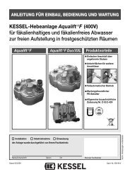
INSTALLATION, OPERATION AND MAINTENANCE INSTRUCTIONS<br />
Sonic<strong>Control</strong> layer thickness measuring device for oil and coalescence separators<br />
Product Advantages<br />
Ultrasonic sensor for precision measurement accurate to centimetres<br />
Monitoring of oil thickness, sludge thickness and blockage<br />
Protective rating ultrasonic probe IP 68<br />
Alarm warning during power outage (Battery back-up)<br />
Installable in all KESSEL oil and coalescence separators<br />
Easy installation (inc. installation set)<br />
Abbildung zeigt Art.Nr. 917824<br />
Installation Commissioning Hand-Over<br />
this unit was installed by the following licensed company<br />
Name/Sign Date Company stamp<br />
Edition: 2011/07<br />
ID-number: 395-120EN<br />
Subject to technical amendments
Table of contents<br />
1. Safety Instructions ......................................................................................................... Page 4<br />
2. General ......................................................................................................... Page 5<br />
2.1 .......System types ..................................................................... Page 6<br />
3. Installation and Assembly 3.1 Installation of the switch unit ............................................... Page 7<br />
3.2 Installation of sensor and sensor bracket............................. Page 8<br />
3.3 Installation dimensions of sensor......................................... Page 11<br />
3.4 Installation example ............................................................ Page 12<br />
4. Electrical connection 4.1 External signal generator .................................................... Page 14<br />
4.2 Shortening the sensor cable ............................................... Page 14<br />
4.3 Extending the sensor cable.................................................. Page 14<br />
4.4<br />
4.5<br />
Installation / cable connection..............................................<br />
Installation in explosion risk areas .......................................<br />
Page<br />
Page<br />
15<br />
17<br />
5. Operation 5.1 .......Prepared for operation ......................................................... Page 18<br />
5.2 Duties of the user................................................................. Page 18<br />
5.3 Instruction / Handover.......................................................... Page 18<br />
6. Inspection and Maintenance .......................................................................................................... Page 19<br />
7. Errors and Malfunction 7.1 ......Incident display ................................................................... Page 20<br />
7.2 ......Fault display......................................................................... Page 21<br />
7.3 ......General faults....................................................................... Page 23<br />
<strong>8.</strong> Switch unit <strong>8.</strong>1 ......Menu navigation................................................................... Page 24<br />
<strong>8.</strong>2 ......System menu ....................................................................... Page 24<br />
<strong>8.</strong>3 ......Information menu ................................................................. Page 25<br />
<strong>8.</strong>3.1 ...Operating hours .................................................................. Page 25<br />
<strong>8.</strong>3.2 ...Log book ............................................................................. Page 25<br />
<strong>8.</strong>3.3 ...<strong>Control</strong> unit type................................................................... Page 25<br />
2
Table of contents<br />
<strong>8.</strong>3.4 ....Servicing date ..................................................................... Page 25<br />
<strong>8.</strong>3.5 ...Current measured values..................................................... Page 25<br />
<strong>8.</strong>3.6 ...Parameters .......................................................................... Page 25<br />
<strong>8.</strong>3.7 ....Measured data memory ...................................................... Page 25<br />
<strong>8.</strong>3.8 ...Disposal .............................................................................. Page 25<br />
<strong>8.</strong>4 ......Servicing menu ................................................................... Page 26<br />
<strong>8.</strong>4.1 ....Manual mode ...................................................................... Page 26<br />
<strong>8.</strong>4.2 ...Servicing dates ................................................................... Page 26<br />
<strong>8.</strong>5 ......Settings menu ...................................................................... Page 27<br />
<strong>8.</strong>5.1 ...Parameters .......................................................................... Page 27<br />
<strong>8.</strong>5.2 ....Profile memory. .................................................................... Page 27<br />
<strong>8.</strong>5.3 ...Date/time.............................................................................. Page 27<br />
<strong>8.</strong>5.4 ....Nominal size ........................................................................ Page 27<br />
<strong>8.</strong>5.5 ....Communication.................................................................... Page 27<br />
<strong>8.</strong>5.6 ...Language............................................................................. Page 27<br />
<strong>8.</strong>5.7 ...Expert mode......................................................................... Page 27<br />
<strong>8.</strong>5.8 ....Reset....................................................................................<br />
<strong>8.</strong>5.9 ...Sonic<strong>Control</strong> model..............................................................<br />
Page<br />
Page<br />
27<br />
27<br />
9. Technical data 9.1 .......Technical Data for <strong>Control</strong> <strong>Unit</strong> ............................................ Page 28<br />
9.2 .......Technical Data for Ultrasonic Sensor................................... Page 29<br />
10. Replacement Parts and Assessories .......................................................................................................... Page 30<br />
11. Connection Plan .......................................................................................................... Page 31<br />
12. Declaration of Conformity .......................................................................................................... Page 32<br />
13. Warranty .......................................................................................................... Page 33<br />
14. Handover Ceritficate .......................................................................................................... Page 34<br />
3
1. Safety Instructions<br />
Dear customer,<br />
Before you put your KESSEL Sonic<strong>Control</strong><br />
into operation, please read through<br />
the installation instructions carefully and<br />
follow them.<br />
Check first whether the system has arrived<br />
undamaged. In case of any transport damage,<br />
please refer to the instructions in chapter<br />
12 "Warranty".<br />
1. Safety instructions:<br />
During installation, operation, maintenance<br />
or repair of the system, the regulations for<br />
the prevention of accidents, the pertinent<br />
DIN and VDE standards and directives, as<br />
well as the directives of the local power supply<br />
industry must be heeded.<br />
Installation, Operation and Service of the<br />
Sonic<strong>Control</strong> may only handled by a professional<br />
licensed service company. The Sonic<strong>Control</strong><br />
may not be repaired , changed or<br />
manipulated. In the case of a product defect,<br />
the entire Sonic<strong>Control</strong> system should be<br />
replaced<br />
Before putting the device into operation,<br />
make sure through professional examination<br />
that the necessary protective features are<br />
available. Grounding, neutral, residual current-operated<br />
protective circuit etc. must<br />
correspond to the requirements of the local<br />
power supply industry.<br />
The system operates on electrical current.<br />
Noncompliance with the operating instructions<br />
may result in considerable damage to<br />
property, personal injuries or even fatal accidents.<br />
The system must be disconnected<br />
from the mains before any work is<br />
carried out on it!<br />
This system is appropriate for explosion<br />
rated areas listed as Ex-<br />
Zone 0.<br />
It must be ensured that the electric cables as<br />
well as all other electrical system equipment<br />
are in a faultless condition. In case of damage,<br />
the system may on no account be put<br />
into operation or must be stopped immediately.<br />
The system must be inspected and serviced<br />
regularly to maintain its operational ability.<br />
We recommend that you conclude a servicing<br />
contract with your installation company.<br />
We recommend that the system is checked<br />
on a weekly basis for proper operation.<br />
The installation of the ultrasonic sensor inside<br />
the separation tank may only take place<br />
when the separator contains no dangerous<br />
wastewater, gases or fumes.<br />
4
2. General<br />
Dear customer,<br />
we are pleased that you have decided to buy a KESSEL product.<br />
The entire system was subjected to a stringent quality control before it left our factory. Nevertheless, please check immediately whether<br />
the system has been delivered to you complete and undamaged. In case of any transport damage, please refer to the instructions in the<br />
chapter “Warranty” in this manual.<br />
These installation, operating and maintenance instructions contain important information that has to be observed during assembly, operation,<br />
maintenance and repair. Prior to carrying out any work on the system, the operator and the responsible technical personnel must<br />
carefully read and heed these installation and operating instructions.<br />
Sonic<strong>Control</strong> for oil and coalescence separators:<br />
The Sonic<strong>Control</strong> measuring device for oil and coalescence separators monitors accurately (to the centimetre) the current layer thickness<br />
of collected oil / fuel on the surface of the separator as well as sludge at the base of the separator and also warns when back-ups<br />
occur into the separator.<br />
Proper Operation:<br />
The UltraSonic sensor is a compact system for installation in EX-Zone 0 rated areas inside oil and coalescence separators. The system<br />
is designed to monitor the following:<br />
O = oil / fuel layer thickness<br />
S = sludge layer thickness<br />
A = Back-up warning<br />
Sonic<strong>Control</strong> is an automatic operated warning system which according to DIN EN 858-1 is recommended for use with oil and coalescence<br />
separators.<br />
The following models are available: 1. OSA, 2. OS, 3. OA, 4. SA, 5. O, 6. S, 7. A<br />
5
2. General<br />
2.1 System types<br />
Sonic<strong>Control</strong> <strong>Control</strong> <strong>Unit</strong><br />
KESSEL AG, 85101 Lenting /Germany<br />
Art.-Nr. 917831<br />
BVS 11 ATEX E 040 X<br />
II (1)G [EX ia Ga] IIB<br />
Sensor Sonic<strong>Control</strong> OSA<br />
KESSEL AG, 85101 Lenting /Germany<br />
Art.-Nr. 917824<br />
BVS 11 ATEX E 040 X<br />
II 1G Ex ia IIA T3 Ga<br />
Sensor Sonic<strong>Control</strong> OS<br />
KESSEL AG, 85101 Lenting /Germany<br />
Art.-Nr. 917825<br />
BVS 11 ATEX E 040 X<br />
II 1G Ex ia IIA T3 Ga<br />
Sensor Sonic<strong>Control</strong> OA<br />
KESSEL AG, 85101 Lenting /Germany<br />
Art.-nr. 917826<br />
BVS 11 ATEX E 040 X<br />
II 1G Ex ia IIA T3 Ga<br />
Sensor Sonic<strong>Control</strong> SA<br />
KESSEL AG, 85101 Lenting /Germany<br />
Art.-Nr. 917827<br />
BVS 11 ATEX E 040 X<br />
II 1G Ex ia IIA T3 Ga<br />
Sensor Sonic<strong>Control</strong> O<br />
KESSEL AG, 85101 Lenting /Germany<br />
Art.-Nr. 917828<br />
BVS 11 ATEX E 040 X<br />
II 1G Ex ia IIA T3 Ga<br />
Sensor Sonic<strong>Control</strong> S<br />
KESSEL AG, 85101 Lenting /Germany<br />
Art.-Nr. 917829<br />
BVS 11 ATEX E 040 X<br />
II 1G Ex ia IIA T3 Ga<br />
Sensor Sonic<strong>Control</strong> A<br />
KESSEL AG, 85101 Lenting /Germany<br />
Art.-Nr. 917830<br />
BVS 11 ATEX E 040 X<br />
II 1G Ex ia IIA T3 Ga<br />
6
3. Installation and Assembly<br />
3.1 Wall mounting of the control unit<br />
The control unit must be installed in a dry and<br />
frost free area – preferable indoors where any<br />
alarms and control unit message can be seen /<br />
heard. Do not install the control unit in direct<br />
sunlight!<br />
Caution!!!! The control unit is not to<br />
be installed inside the oil or coalescence<br />
separator!!!<br />
In order to mount the control unit the control unit<br />
cover does not need to be opened. Pre-drill 2 x<br />
6mm diameter holes 168mm apart (use the drilling<br />
template if required)<br />
Installation:<br />
1. Drill two holes<br />
2. Insert two dowels<br />
3. Screw in two screws to proper depth<br />
4. Hang control unit on two screws<br />
5. Affix the control unit on the screws by pushing<br />
the control unit down until it seat firmly<br />
on both screws.<br />
Illustration of Sonic<strong>Control</strong> control unit<br />
7
3. Installation and Assembly<br />
Installation Sonic<strong>Control</strong><br />
The Sonic<strong>Control</strong> should be completely disconnected<br />
form power before the system is<br />
installed or during any maintenance work.<br />
The system should only be connected to<br />
power after the control unit and the ultrasonic<br />
sensor have connected. The ID sticker<br />
on the control unit should not be removed.<br />
3.2 Installation of sensor and sensor<br />
bracket<br />
The sensor is properly protected and may be<br />
installed in Zone 0 explosion rated areas according<br />
to 94/9/EG (ATEX).<br />
The cable and the ID sticker are an integral<br />
part of the product. The ID sticker must remain<br />
on the cable if the cable is to be shortened.<br />
If a conduit is required to lay the<br />
cable, it is recommended that a conduit with<br />
50mm diameter is used.<br />
The ultrasonic sensor is IP 68 protected and<br />
is weather and oil / fuel resistant – due to this<br />
is can be installed in oil and coalescence separators.<br />
The ultrasonic sensor is designed for use in<br />
temperatures from -10 deg C to + 50 deg C<br />
(263K to 323K)<br />
Sensors certified for use in explosion<br />
risk areas<br />
In oil and coalescence separators, sensors<br />
can only be installed that are certified for use<br />
in explosion risk areas.<br />
The ultrasonic installation bracket must be<br />
installed with the supplied screws inside the<br />
upper section of the fuel separator – this<br />
area is above fluid level meaning the installation<br />
screws holes will not cause any leaks<br />
to the watertight system.<br />
Caution!!!! If the ultrasonic sensor is being<br />
installed in a fuel or coalescence separator<br />
that is already in use, no electric or battery<br />
powers tools such as drills may be used during<br />
installation. Only use normal hand help<br />
screw drivers.<br />
If back-up (flooding) has occurred<br />
within the separator, the ultrasonic<br />
sensor should be inspected afterwards<br />
that it is still in the proper location<br />
and then it is clear of debris.<br />
Please note the safety instructions!<br />
8
3. Installation and Assembly<br />
Article Number of oil or coalescence separator Sludge Oil / Fuel<br />
Distance<br />
1) % full Measured layer Disposal 2) % full Measured layer Disposal greens mark<br />
thickness volume thickness volume to Container<br />
in mm in liters in mm in liters ground<br />
99403.10B 99403.10BEX 99503.10B 99503.10BEX 50 650 1000 100 131 187<br />
99403.10D 99403.10DEX 99503.10D 99503.10DEX 40 530 800 80 105 150<br />
30 430 600 60 79 112 1050<br />
20 330 400 40 52 75<br />
10 210 200 20 26 37<br />
99610.15B 99610.15BEX 99710.15B 99710.15BEX 50 650 1500 100 131 262<br />
99610.15D 99610.15DEX 99710.15D 99710.15DEX 40 550 1200 80 105 210<br />
30 450 900 60 79 157 1050<br />
20 340 600 40 52 105<br />
10 220 300 20 26 52<br />
99606.30B 99606.30BEX 99706.30B 99706.30BEX 50 1100 3000 100 138 265<br />
99606.30D 99606.30DEX 99706.30D 99706.30DEX 40 930 2400 80 110 212<br />
99610.30B 99610.30BEX 99710.30B 99710.30BEX 30 760 1800 60 83 159 1550<br />
99610.30D 99610.30DEX 99710.30D 99710.30DEX 20 580 1200 40 55 106<br />
10 370 600 20 28 53<br />
99606.80B 99606.80BEX 99706.80B 99706.80BEX 50 1100 4000 100 138 380<br />
99606.80D 99606.80DEX 99706.80D 99706.80DEX 40 910 3200 80 110 304<br />
99610.80B 99610.80BEX 99710.80B 99710.80BEX 30 740 2400 60 83 228 1550<br />
99610.80D 99610.80DEX 99710.80D 99710.80DEX 20 560 1600 40 55 152<br />
99615.80B 99615.80BEX 99715.80B 99715.80BEX 10 350 800 20 28 76<br />
99615.80D 99615.80DEX 99715.80D 99715.80DEX<br />
1)The separator contents should be emptied when the sludge layer is 50% full<br />
2)The separator contents should be emptied when the oil / fuel layer is 80% full – not disposing at this stage would exceed the oil / fuel storage capacity of the separator<br />
9
3. Installation and Assembly<br />
Article Number of oil or coalescence separator Sludge Oil / Fuel<br />
Distance<br />
1) % full Measured layer Disposal 2) % full Measured layer Disposal<br />
greens mark<br />
thickness volume thickness volume to Container<br />
in mm in liters in mm in liters<br />
ground<br />
99703.04B 50 400 550 100 235 200<br />
99703.04D 40 320 369 80 188 160<br />
30 240 305 60 141 120 980<br />
20 160 241 40 94 80<br />
10 80 177 20 47 40<br />
99703.10B 50 800 1050 100 235 200<br />
99703.10D 40 640 815 80 188 160<br />
30 480 587 60 141 120 1480<br />
20 320 369 40 94 80<br />
10 160 241 20 47 40<br />
99706.10B 50 400 550 100 235 200<br />
99706.10D 40 320 369 80 188 160<br />
30 240 305 60 141 120 940<br />
20 160 241 40 94 80<br />
10 80 177 20 47 40<br />
1)The separator contents should be emptied when the sludge layer is 50% full<br />
2)The separator contents should be emptied when the oil / fuel layer is 80% full – not disposing at this stage would exceed the oil / fuel storage capacity of the separator<br />
Adjustment of the Sonic<strong>Control</strong> sensor can be handled with two different methods:<br />
1) By measuring with a ruler (separator must be empty in order to use this method)<br />
2) The sensor is adjusted using the colored marks. The separator must be filled with clean water in order to use this method<br />
(must not be filled with oil or fuel).<br />
10
3.3 Installation of sensor holding bracket.<br />
3. Installation and Assembly<br />
1. Open the cover on the oil or coalescence separator<br />
(use caution removing the heavy cast iron<br />
or concrete covers – a lifting aid system is recommended.<br />
2. Using the including drilling template bracket,<br />
mark on the upper section of the separator the<br />
two holes located on the bracket. Drill two 6mm<br />
holes in the location of the two marks.<br />
3. Screw the two included screws into the two<br />
holes in the upper section until there is a distance<br />
of 25mm between screw head and<br />
upper section wall.<br />
4. In the case that the separator has installed deeper<br />
than the standard installation depths, use<br />
the supplied pipe (D) as an extension.<br />
5. Now clip the Sonic<strong>Control</strong> sensor in the holding<br />
clips (C) and then secure the bracket (B) by<br />
handing it onto the two screws. Now fully tighten<br />
the two screws so that the bracket is securely<br />
fixed to the separator’s upper section<br />
6. Now adjust the Sonic<strong>Control</strong> sensor to the<br />
green mark on the sensor with the full water<br />
level (for information on the sensor green mark,<br />
please see the next page.<br />
B<br />
C<br />
D<br />
A<br />
Caution – the Sonic-<br />
<strong>Control</strong>’s cable should<br />
not be in the way or<br />
above any of the sensor<br />
probes<br />
11
3. Installation and Assembly<br />
3.4 Installation Example<br />
The sensor should be installed<br />
so that the sensor<br />
fingers point toward the<br />
center of the tank, this will<br />
protect the sensors from<br />
any debris that may fall<br />
into the separator.<br />
The sensor should be installed<br />
so that the base of<br />
the pointed green arrow is<br />
at the exact height of the<br />
separator's water level during<br />
calm / clean conditions<br />
(no fuel or oil in separator)<br />
Distance between base<br />
of pointed green arrow<br />
and chamber bottom<br />
(for dimensions see<br />
table S.9<br />
12
3. Installation and Assembly<br />
Ill. shows an underground fuel separator size NS 7 to NS 20 Ill. shows an underground fuel separator size NS 1 to NS 4<br />
inside<br />
Order-Nr. 917822<br />
outside<br />
During the installation of the underground fuel separator, a DN 40 (OD 50mm) conduit pipe should<br />
be laid two the separator dome that will contain the Sonic<strong>Control</strong> sensor. In the dome area of the<br />
separator tank (as seen in the above ill.) a 60mm hole should be drilled out of the tank using a<br />
hole saw. The control unit and the separator should be located as close to each other as possible.<br />
The conduit pipe should be laid with no bends over 45 degree (maximum fitting bend should<br />
be 45 degrees). The conduit pipe should be installed with a constant slope toward the separator<br />
so that any condense water will flow back into the separator and not toward the control unit or<br />
pond in the conduit pipe. In the case that the conduit may need to be extended at a later date or<br />
the sensor cable needs to be replaced, a string can by laid in the conduit pipe to aid running new<br />
cables. The Sonic<strong>Control</strong> cable may be extended to a total length of 30 meters. The cable screw<br />
must be tightly fastened before running the Sonic<strong>Control</strong> cable back toward the control unit. Finally<br />
secure tightly the black plastic conduit pipe cover. If a back up occurs inside the separator<br />
the Sonic<strong>Control</strong> sensor must be inspected and cleaned if necessary.<br />
13
4.1 External Signalling device<br />
The external signalling (alarm) device (Article<br />
number 20162) can be connected inside<br />
the control unit if required. This device is<br />
used so that audible alarms can be heard in<br />
other locations of the building<br />
4.2 Shortening the Sonic<strong>Control</strong> cable<br />
The Sonic<strong>Control</strong> cable can be shortened if<br />
required. If cable jackets are used the<br />
connection jacks must be able to handle a<br />
cross sectional area of max 2.5 square mm.<br />
This cross sectional area cannot be exceeded<br />
ATEX regulations should be followed if<br />
shortening the Sonic<strong>Control</strong> cable – ATEX<br />
Standard 94/9/EG<br />
4.3 Extending the Sonic<strong>Control</strong> cable<br />
The Sonic<strong>Control</strong> sensor is supplied with 3<br />
x 0.75 square mm cables inside a jacket<br />
with a length of 30 m. Due to electromagnetic<br />
interference, extending this cable<br />
may only be done under limitations. Please<br />
contact the KESSEL Customer Service department<br />
if this is to be done.<br />
4. Electrical Connections<br />
14
4. Electrical Connections<br />
4.4 Installation / Cable Connections<br />
The Sonic<strong>Control</strong> cable may not be laid with<br />
together with any other electrical systems /<br />
circuits. Do not lay the cable parallel with<br />
any other cables in order to prevent an electrical<br />
interference which can cause the Sonic<strong>Control</strong><br />
to malfunctions. The sensor itself<br />
should not be grounded.<br />
The Sonic<strong>Control</strong> cable is to be connected<br />
to the control unit as stated in this manual.<br />
Connect the cable to the connection jacks<br />
located on the left side inside the control<br />
unit near the partition wall.<br />
IMPORTANT:<br />
All cables entering the control unit should be secured<br />
properly secured with a tie-wrap or cable<br />
clip to prevent any danger to the unit or the operator<br />
in the case that a cable connection comes<br />
loose. The sensor cable should be laid separately<br />
from the control unit’s power cable to prevent<br />
interference<br />
15
4. Electrical Connections<br />
<br />
<br />
<br />
<br />
<br />
<br />
<br />
<br />
<strong>Control</strong> unit digital display<br />
Movement keys / direction keys for moving<br />
through the program menu<br />
Enter key / OK key<br />
Return key / ESC key<br />
LED for operation<br />
LED for malfuctions / warnings<br />
Power cable<br />
Sonic<strong>Control</strong> sensor cable connection<br />
(Article Number 395-074 . . . 395-080)<br />
Moden connection<br />
Remote warning speaker connection<br />
Potential free contact connection<br />
USB connection<br />
* 9, 10 and 11 – see connection plan on page 31<br />
<br />
16
4. Electrical Connections<br />
4.5 Installation of electrical equipment in<br />
explosion risk areas<br />
The self protected electrical systems of the<br />
Sonic<strong>Control</strong>, which are identified by their blue<br />
color, are certified for installation in explosion<br />
risk areas and to be used with the Ex i-connections<br />
of the Sonic<strong>Control</strong> ATEX.<br />
The electrical installation in explosion risk<br />
areas must follow EN 60079-0 and EN 60079-<br />
14 regulations.<br />
Installations in Germany must also follow EIN<br />
60079-14VDE 0165 Part 1 regulations.<br />
When connecting the intrinsically secured circuit<br />
of the associated equipment - installation<br />
in a secure area- (Sonic<strong>Control</strong> ATEX control<br />
unit) and when connecting of the intrinsically<br />
secured equipment - installation in explosion<br />
rated area - (Sonic<strong>Control</strong> ATEX sensor), be<br />
sure that all related max values (U; I; P) are followed<br />
and met.<br />
Sine the connection of both explosion protected<br />
systems have been certified with the EG<br />
type examination certificate BVS 11 ATEX E<br />
040 X, no individual verification is required according<br />
to RL 94/9/EG and ATEX 95.<br />
Related Norms and Regulations<br />
EN 60079-0:2010-03 (Explosion risk areas /<br />
atmospheres)<br />
EN 60079-11:2007-08 (Protection classes,<br />
self safety; Ex i)<br />
EN 60079-26:2007-10 (Operating material<br />
with system protection level (EPL Ga)<br />
EN 60079-14:2009-05 (Explosion risk areas /<br />
connection of electronic systems)<br />
EN 61000-6-1 (2007 (interference resistance)<br />
EN 61000-6-3 (2007) (emitted interference)<br />
Regulation RL94/9/EG (ATEX 95)<br />
Low current regulations 2006/95/EG<br />
17
5.1 Getting the system ready for operation<br />
Plug the mains plug of the control unit into<br />
the socket. The system will initialise automatically.<br />
During initial initialisation of the system, the<br />
control unit requires that the user select four<br />
basic settings.<br />
1. Language<br />
2. Date/time<br />
3. Type of system*<br />
4. Typ of coalesence separator*<br />
➤ Selection using ▲<br />
▼<br />
➤ Stored in system memory by pressing<br />
“OK”<br />
➤ After setting 1 to 4<br />
➤ Switch unit loads program memory<br />
➤ Start operating mode<br />
➤ System is ready for operation<br />
5. Operation<br />
5.2 Operator's duties<br />
Checks<br />
- for transport or installation damage<br />
- for structural defects of all electrical and<br />
mechanical components for seat and function<br />
- the cable connections<br />
Customer instruction based on the installation<br />
and operating instructions<br />
- Go through installation and operating instructions<br />
with the customer<br />
- System operation (explaining and describing)<br />
- Explanation to the customer about the<br />
operator’s duties<br />
- Remind about regular servicing (see chapter<br />
6)<br />
5.3 Instruction / Handover<br />
The chapter "Safety instructions" must<br />
be heeded (page 4)!<br />
Commissioning is carried out by a specialised<br />
firm or by an authorised KESSEL agent<br />
(at an additional charge). The following persons<br />
should be present for the handover:<br />
- Person authorised to perform the acceptance<br />
on behalf of the building owner<br />
- Specialised firm<br />
In addition, we recommend the participation<br />
of operating personnel/operator and the<br />
waste disposal contractor.<br />
Summary of instructions:<br />
- Get the system ready for operation<br />
- Check the system<br />
- Instruction based on the installation and<br />
operating instructions<br />
- Preparation of the handover certificate<br />
(see chapter 13)<br />
➤ Once instruction is completed, the system<br />
must be made ready for operation<br />
.<br />
18
6. Inspection and Maintenance<br />
Please heed the safety instructions in chapter 1.<br />
All power should be disconnected from the system when any maintenance<br />
or service work is being performed. If the two 9-volt batteries<br />
in the control unit are to be replaced, use only 450 mAh types.<br />
Repairs to this system should only be handed by the manufacturer.<br />
The control unit itself requires no maintenance.<br />
Cable connections should be checked for damage.<br />
The Sonic<strong>Control</strong> sensor needs to be cleaned on a regular basis.<br />
Every time the oil / coalescence separator is emptied / disposed, the<br />
sensor must be cleaned with<br />
warm/hot water*. When a high-pressure jet cleaner is used, maintain<br />
a safe distance of 30 cm.<br />
The sensor does not have to be removed for cleaning.<br />
The Sonic<strong>Control</strong> control unit and the sensor are connected by a<br />
cable with a maximum total length of 30 meters. Only this cable<br />
should be used, no other cable is allowed for connection. If this<br />
cable needs to be cleaned, used only a moist towel to prevent any<br />
build up of static electricity.<br />
The sensor may not be used with corrosive fluids.<br />
The sensor is maintenance free. In order to assure proper operation<br />
of the entire system, the sensor function should be checked once<br />
per year.<br />
Repairs<br />
The Sonic<strong>Control</strong> system may not be repaired, changed or manipulated.<br />
In case the Sonic<strong>Control</strong> is damaged or defective it must<br />
be replaced by a new system.<br />
Disposal<br />
In the case that the Sonic<strong>Control</strong> is damaged or no longer required<br />
and needs to be disposed of, please follow all local and national disposal<br />
regulations in your area.<br />
The Sonic<strong>Control</strong> control unit contains two 9-volt batteries which<br />
should be disposed of properly.<br />
Please follow this all the safety instructions in this operating manual<br />
when operating this system.<br />
19
7. Errors and Malfunction<br />
Please heed the safety instructions in chapter 1.<br />
7.1 Incident display (only in the log book):<br />
Message on digital display Cause Remedy<br />
First initialisation First initialisation - -<br />
Parameters changed Parameters have been changed - -<br />
Type of system changed Type of system has been changed - -<br />
Servicing Servicing date has been entered - -<br />
Manual mode Manual mode has been entered - -<br />
Readout log book Log book has been read out - -<br />
Shut down control unit <strong>Control</strong> unit has been shut down - -<br />
Acknowledge acoustic alarm Acoustic alarm has been acknowledged - -<br />
Acknowledge fault Fault has been acknowledged - -<br />
Factory settings Return to factory settings - -<br />
KESSEL Customer Service Contact – telephone +49 8456 27 462<br />
20
7. Errors and Malfunction<br />
7.2 Errors and Malfunctions<br />
Message on digital display Type of warning Cause Remedy<br />
PRE-ALARM layer thickness Blinking (alarm) Oil / Fuel layer has Monitor oil / fuel<br />
reached pre-alarm<br />
layer and dispose<br />
thickness<br />
when required<br />
No rest phase detected Blinking (alarm) Measurement took place Check measurement in<br />
during operation (waste- Parameter section of control<br />
water entering separator) unit and re-set if required<br />
– inaccurate results<br />
ALARM layer thickness Acoustical alarm and Maximum oil / fuel Dispose separator contents<br />
flashing LED<br />
layer thickness reached<br />
Power outage Acoustical alarm System is no longer Check fusing, F1 switch<br />
and flashing LED received power and mains power supply<br />
21
7. Errors and Malfunction<br />
Message on digital display Type of warning Cause Remedy<br />
Communication error Acoustical alarm and Insufficient modem Step 1 – check reception<br />
flashing LED reception Step 2 – If no reception is<br />
then do not use modem, if<br />
reception is existing then<br />
replace modem<br />
Extend GSM antenna<br />
KESSEL Customer Service Contact – telephone +49 8456 27 462<br />
22
7. Errors and Malfunction<br />
7.3 General Errors<br />
Known error Type of warning Cause Remedy<br />
Difference between displayed<br />
oil / fuel layer thickness and<br />
manually measured thickness<br />
SMS use or remote maintenance<br />
not possible<br />
Error due to improper<br />
Sonic<strong>Control</strong> measurement<br />
- Sonic<strong>Control</strong> sensor<br />
improperly connected<br />
- Sonic<strong>Control</strong> position<br />
incorrect<br />
- Improper initialization<br />
- Debris on sensor<br />
- Separator size / Article<br />
number improperly entered<br />
- Check all cable connections<br />
(please follow section 3.4 – Installation)<br />
- Check to make sure type and<br />
size of separator has been<br />
correctly entered<br />
- Service the oil / fuel separator<br />
- Empty / dispose of separator<br />
and clean Sonic<strong>Control</strong> sensor<br />
- Check sensor position and reposition<br />
if necessary (see p. 11)<br />
- Check settings and correct if necessary<br />
Remote maintenance error Insufficient modem reception Step 1 – check modem reception<br />
Step 2 - If no reception is available<br />
then do not use modem,<br />
if reception is existing then<br />
replace modem<br />
Extend GSM antenna<br />
23
<strong>8.</strong>1 Menu guidance<br />
The control unit's menu navigation is subdivided<br />
into the systeminformation as well<br />
as three different main menu items. The<br />
background lighting is activated if one of<br />
the control keys is pressed once.<br />
OK Button: Skips to the next higher<br />
level<br />
ESC Button: Skip to the next lower level<br />
▲<br />
Navigation within a level<br />
▼<br />
Alarm Button The acoustic signal can be<br />
acknowledged by pressing<br />
this key once. If the fault<br />
has been eliminated, the<br />
visual fault can also be<br />
acknowledged by pressing<br />
the alarm key again for 3<br />
seconds or more.<br />
If the fault has not been eliminated, the<br />
acoustic alarm is triggered again when<br />
the alarm key is pressed again.<br />
<strong>8.</strong> <strong>Control</strong> <strong>Unit</strong><br />
In case of a mains power failure, the system<br />
is not ready for operation. The control<br />
unit switches to stand-by mode (battery<br />
operation) which will last for at least<br />
72 hours if the batteries are completely<br />
full. This becomes noticeable by means of<br />
an acoustic and visual alarm. The acoustic<br />
alarm can be acknowledged by pressing<br />
the alarm key. By pressing the Alarm<br />
button for 5 seconds or more, the power<br />
outage warning mode can be achknowledged<br />
and the control unit will be automatically<br />
turned off – this can serve to<br />
save battery power. If the mains connection<br />
is re-established, the program will automatically<br />
continue with the last program<br />
phase.<br />
Note:<br />
Certain menus are password-protected.<br />
This serves to protect the system against<br />
inappropriate use.<br />
If you have any questions, please contact<br />
KESSEL Customer Services (Phone +49<br />
(0) 8456 / 27462)<br />
<strong>8.</strong>2 System-Menü<br />
System info<br />
Informations<br />
Maintenance<br />
Settings<br />
24
<strong>8.</strong>3 Information menu<br />
System info Informations<br />
Maintenance<br />
Settings<br />
Operating hours<br />
Log book<br />
<strong>Control</strong> unit type<br />
Servicing date<br />
Current measured<br />
values<br />
Parameters<br />
Measured data<br />
Disposal<br />
<strong>8.</strong> <strong>Control</strong> <strong>Unit</strong><br />
<strong>8.</strong>3.1 Operating hours<br />
Display of all system operating times.<br />
<strong>8.</strong>3.2 Log book<br />
Chronological display of incidents and faults (see also chapter 7 “Incidents and<br />
faults / remedial measures”)<br />
All changes made to the settings are saved at this point.<br />
<strong>8.</strong>3.3 <strong>Control</strong> unit type<br />
Display of system time, grease separator type, language and software status.<br />
<strong>8.</strong>3.4 Servicing date<br />
Display of the next necessary and last performed servicing.<br />
Note: Data are only available if these have been stored in the “Settings” menu by<br />
the servicing partner.<br />
<strong>8.</strong>3.5 Current measured values<br />
Pressing the OK key carries out a measurement of the current<br />
grease layer thickness.<br />
<strong>8.</strong>3.6 Parameters<br />
Display of all set control parameters of the system It is not possible to change the<br />
parameters in this menu.<br />
<strong>8.</strong>3.7 Measured data<br />
Display of the last layer thickness and temperature stored (max. 400 values).<br />
<strong>8.</strong>3.8 Disposal<br />
Display of details of the last disposal carried out (if stored)<br />
25
<strong>8.</strong> <strong>Control</strong> <strong>Unit</strong><br />
<strong>8.</strong>4 Maintenance menu<br />
System info Informations<br />
Maintenance<br />
Settings<br />
Manual operation<br />
Servicing dates<br />
Data saving /<br />
storage<br />
activation<br />
Remote<strong>Control</strong><br />
<strong>8.</strong>4.1 Manual mode<br />
Manual operation overrides automatic operation.<br />
<strong>8.</strong>4.2 Servicing date<br />
Entry of date of last service / maintenance and the next servicing date by the servicing<br />
partner.<br />
<strong>8.</strong>4.3 Data saving / storage<br />
Using the data storage, measured Sonic<strong>Control</strong> values can be transferred onto a<br />
USB stick<br />
<strong>8.</strong>4.4 Remote <strong>Control</strong> activation<br />
Here you have the capability or activating a remote control (optional accessory)<br />
26
<strong>8.</strong> <strong>Control</strong> <strong>Unit</strong><br />
<strong>8.</strong>5 Settings menu<br />
System info Information<br />
Servicing<br />
Settings<br />
Parameter<br />
Profile memory<br />
Date / time<br />
Type of System<br />
Communication<br />
Language<br />
External modus<br />
Reset<br />
Sonic<strong>Control</strong><br />
model<br />
<strong>8.</strong>5.1 Parameters<br />
Changes to default parameter settings (refer also to 3.3)<br />
Note: Every change is immediately accepted when the OK key is pressed. In addition,<br />
when exiting this menu it is possible to save these values in the profile memory<br />
under a separate name.<br />
<strong>8.</strong>5.2 Profile memory<br />
Loading of the values accepted on initialisation and of the values added under a<br />
new name (see <strong>8.</strong>5.1).<br />
<strong>8.</strong>5.3 Date/time Setting the current date and time.<br />
<strong>8.</strong>5.4 Type of system<br />
Selection of the separator size (NS).<br />
<strong>8.</strong>5.5 Communication<br />
Input / change of the station name, the device number, the modem type, the PINS<br />
and the number of the mobile phone to which possible malfunctions can be sent<br />
by text message (for a detailed description see separate operating instructions).<br />
<strong>8.</strong>5.6 Language Display / change of digital display language.<br />
<strong>8.</strong>5.7 Expert mode access only by KESSEL Customer Service<br />
<strong>8.</strong>5.8 Reset<br />
Reset the switch unit to the default setting (operating hours are not reset).<br />
<strong>8.</strong>5.9 Sonic<strong>Control</strong> model<br />
In this mode, Sonic<strong>Control</strong> models from Model O to Model OSA can be selected<br />
27
9. Technical Data<br />
9.1 <strong>Control</strong> <strong>Unit</strong> technical data<br />
General technical data<br />
Housing dimensions (L x W x H) 190 x 210 x 70 mm<br />
Weight of switch unit approx 1.3 kg<br />
Permissible temperature range 0 bis 50 °C<br />
Mains standby (ready for operation) 14 mA<br />
Mains current in operation<br />
35 mA<br />
Protective class<br />
I<br />
Type of protection IP 54<br />
Electrical connections suitable for<br />
all copper conductors<br />
0,08 - 2,5 mm<br />
Cable sheath diameter<br />
5 - 9 mm<br />
Battery<br />
2 x 9V – 680 mAh<br />
Power Supply<br />
Operating voltage<br />
Mains connection<br />
Pre-fuse required<br />
230 V AC<br />
1~50 Hz ± 10% L / N<br />
Safety plug on the switch<br />
unit with 1.4 m connection<br />
cable<br />
max. 16 A (provide on installation<br />
side), all-pole<br />
main switch in the supply<br />
cable<br />
Inputs<br />
Sensor input<br />
Outputs<br />
Potential-free<br />
Option: Signal generator<br />
(Article Nr. 20162)<br />
Sensor input Sonic<strong>Control</strong><br />
• Changeover contact: centre contact,<br />
• Make contact; break contact<br />
• max. 42 VAC / 0.5 A<br />
Connection possibility<br />
for an external alarm device<br />
28
9. Technical Data<br />
9.2 Sensor Technical Data<br />
General Technical Data<br />
Housing Dimensions (L x W x H)<br />
<strong>Control</strong> unit weight<br />
700 x 200 x70 mm<br />
approx 0.7 kg without<br />
sensor cable<br />
Allowable operating temp. range 0 bis 50 °C<br />
Protection class IP 68<br />
Safety related maximum sensor values<br />
Intrinsically safe [Kl. Ue (+) / Kl. GND (-)]<br />
supply circuit<br />
Ui ≤ 7,88 V; li ≤ 277 mA;<br />
Pi ≤ 544 mW;<br />
Characteristic curve: linear Ci + Li<br />
Negligibly small<br />
Intrinsically safe [Kl. LIN (+) / Kl. GND (-)]<br />
outgoing circuit<br />
Ui ≤ 7,88 V; li ≤ 20,4 mA;<br />
Pi ≤ 40,2 mW;<br />
Characteristic curve: linear Ci + Li<br />
Negligibly small<br />
29
10. Replacement Parts and Accessories<br />
➀<br />
➁<br />
➂<br />
inside<br />
outside<br />
Article<br />
Order Nr<br />
11. <strong>Control</strong> unit 395-037<br />
12. Ultra sonic sensor OSA 917840<br />
OS 917841<br />
OA 917842<br />
SA 917843<br />
O 917844<br />
A 917846<br />
3. Cable conduit wall penetration system (for underground separators) 917822<br />
4. Alarm speaker 20162<br />
O = oil / fuel layer measurement<br />
S = sludge layer measurement<br />
A = Back up / over flow warning<br />
30
11. Connection Plan<br />
31
13. Warranty<br />
1. In the case that a KESSEL product is defective, KESSEL has the<br />
option of repairing or replacing the product. If the product remains<br />
defective after the second attempt to repair or replace the product<br />
or it is economically unfeasible to repair or replace the product, the<br />
customer has the right to cancel the order / contract or reduce payment<br />
accordingly. KESSEL must be notified immediately in writing<br />
of defects in a product. In the case that the defect is not visible or<br />
difficult to detect, KESSEL must be notified immediately in writing of<br />
the defect as soon as it is discovered. If the product is repaired or<br />
replaced, the newly repaired or replaced product shall receive a new<br />
warranty identical to that which the original (defective) product was<br />
granted. The term defective product refers only to the product or part<br />
needing repair or replacement and not necessarily to the entire product<br />
or unit. KESSEL products are warranted for a period of 24<br />
month. This warranty period begins on the day the product is shipped<br />
form KESSEL to its customer. The warranty only applies to<br />
newly manufactured products. Additional information can be found<br />
in section 377 of the HGB.<br />
In addition to the standard warranty, KESSEL offers an additional 20<br />
year warranty on the polymer bodies of class I / II fuel separators,<br />
grease separators, inspection chambers, wastewater treatment systems<br />
and rainwater storage tanks. This additional warranty applies<br />
to the watertightness, usability and structural soundness of the product.<br />
A requirement of this additional warranty is that the product is properly<br />
installed and operated in accordance with the valid installation<br />
and user's manual as well as the corresponding norms / regulations.<br />
2. Wear and tear on a product will not be considered a defect. Problems<br />
with products resulting from improper installation, handling or<br />
maintenance will also not be considered a defect.<br />
Note: Only the manufacturer may open sealed components or screw<br />
connections. Otherwise, the warranty may become null and void<br />
01.06.2010<br />
33
14. Commissioning Protocol for installer<br />
Type:<br />
__________________________________________________________<br />
Day / Hour<br />
__________________________________________________________<br />
Project description /Building services supervisor __________________________________________________________<br />
Address/Telephone / Fax<br />
__________________________________________________________<br />
Builder<br />
__________________________________________________________<br />
Address/Telephone / Fax<br />
__________________________________________________________<br />
Planner<br />
__________________________________________________________<br />
Address/Telephone / Fax<br />
__________________________________________________________<br />
Contracted plumbing company<br />
__________________________________________________________<br />
Address/Telephone / Fax<br />
__________________________________________________________<br />
KESSEL-Commissions no.:<br />
System operator /owner<br />
__________________________________________________________<br />
Address/Telephone / Fax<br />
__________________________________________________________<br />
User<br />
__________________________________________________________<br />
Address/Telephone / Fax<br />
__________________________________________________________<br />
Person of delivery<br />
Other remarks<br />
__________________________________________________________<br />
The system operator, and those responsible, were present during the commissioning of this system.<br />
____________________________ ____________________________ ____________________________<br />
Place and date Signature owner Signature user<br />
34
14. Handover Cerificate<br />
Handover certificate (copy for the company carrying out the installation)<br />
❏<br />
❏<br />
❏<br />
The initial operation and instruction was carried out in the presence of the person authorised to perform the acceptance<br />
and the system operator.<br />
The system operator/person authorised to perform the acceptance was informed about the obligation to service the<br />
product according to the enclosed operating instructions.<br />
Initial operation and instruction were not carried out.<br />
The client/ person responsible for initial operation was handed the following components and/or product components<br />
Initial operation and instruction is being carried out by (company, address, contact, phone)<br />
The exact coordination of the dates for initial operation/instruction is being carried out by the system operator and person responsible<br />
for initial operation.<br />
<br />
Place, date Signature of person Signature of system operator Signature of the company<br />
authorised to perform acceptance<br />
carrying out the installation work<br />
35
❑ Backwater protection<br />
❑ Lifting Stations and pumps<br />
❑ Drains and shower channels<br />
❑ Separators<br />
-Grease Separators<br />
-Oil-/Fuel-/Coalescence Separators<br />
-Starch Separators<br />
-SedimentSeparators<br />
❑ Septic Systems<br />
❑ Inspection Chambers<br />
❑ Rainwater Management Systems