Verification and Validation of a Safety-Critical Steer-By-Wire System ...
Verification and Validation of a Safety-Critical Steer-By-Wire System ...
Verification and Validation of a Safety-Critical Steer-By-Wire System ...

Create successful ePaper yourself
Turn your PDF publications into a flip-book with our unique Google optimized e-Paper software.
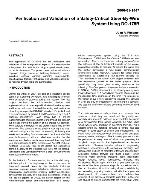
2006-01-1447<br />
<strong>Verification</strong> <strong>and</strong> <strong>Validation</strong> <strong>of</strong> a <strong>Safety</strong>-<strong>Critical</strong> <strong>Steer</strong>-<strong>By</strong>-<strong>Wire</strong><br />
<strong>System</strong> Using DO-178B<br />
Copyright © 2005 SAE International<br />
Juan R. Pimentel<br />
Kettering University<br />
ABSTRACT<br />
The application <strong>of</strong> DO-178B for the verification <strong>and</strong><br />
validation <strong>of</strong> the safety-critical aspects <strong>of</strong> a steer-by-wire<br />
sub-system <strong>of</strong> a vehicle by using a spiral development<br />
model is discussed. The project was performed within a<br />
capstone design course at Kettering University. Issues<br />
including lessons learned regarding requirements,<br />
specifications, testing, verification, <strong>and</strong> validation activities<br />
as required by DO-178B are summarized.<br />
INTRODUCTION<br />
During the winter <strong>of</strong> 2004, as part <strong>of</strong> a capstone design<br />
course at Kettering University, two challenging projects<br />
were assigned to students taking this course. The first<br />
project involved the microcontroller design <strong>and</strong><br />
implementation <strong>of</strong> a safety-critical steer-by-wire system<br />
<strong>and</strong> the second project involved the testing <strong>and</strong> verification<br />
<strong>of</strong> such system per the DO-178B st<strong>and</strong>ard. Projects 1 <strong>and</strong><br />
2 were performed by groups 1 <strong>and</strong> 2 comprised by 9 <strong>and</strong> 7<br />
students respectively. Each group had a project<br />
leader/manager <strong>and</strong> its members were divided into smaller<br />
sub-groups during the duration <strong>of</strong> the project. All activities<br />
were carefully monitored by the group leaders <strong>and</strong> by the<br />
instructor. The schedule <strong>of</strong> the projects was tight as they<br />
had to fit during a school term at Kettering University (10<br />
weeks not including final assessment). At the end <strong>of</strong> the<br />
term, both groups delivered what was required by the<br />
instructor <strong>and</strong> both projects were successful as they lead<br />
to a demonstration to SAE members on April 24, 2004 at<br />
Kettering University. This paper details the experience<br />
gained in applying the st<strong>and</strong>ard DO-178B for the testing,<br />
verification, <strong>and</strong> validation (V&V) <strong>of</strong> a steer-by-wire system<br />
in an academic environment.<br />
As the instructor for such course, the author did many<br />
activities prior to the beginning <strong>of</strong> the school term to<br />
document several items for the students including<br />
overview, purpose, scope, definitions, references, project<br />
organization, management process, system architecture<br />
development process, <strong>and</strong> expected deliverables. Prior to<br />
this course (spring <strong>of</strong> 2003), an earlier project on the<br />
microcontroller design <strong>and</strong> implementation <strong>of</strong> a safetycritical<br />
steer-by-wire system using the S12 from<br />
Freescale <strong>and</strong> CAN drivers from Vector CANTech Inc. was<br />
undertaken. This project was not entirely successful as<br />
the s<strong>of</strong>tware <strong>of</strong> the fault-tolerant aspects <strong>of</strong> the project<br />
proved too complex to manage. At around the same time<br />
the author developed a CAN-based communication<br />
architecture called FlexCAN, suitable for safety-critical<br />
applications by addressing fault-tolerant aspects [4].<br />
Thus, students in the winter 2004 project benefited from<br />
the experience gained in the earlier projects. More<br />
specifically, they were given working versions <strong>of</strong> the<br />
following: FlexCAN protocol (implemented as a simulation<br />
in CANoe), CANoe simulator for the steer-by-wire system,<br />
locally developed S12 CAN drivers capable <strong>of</strong> using all five<br />
independent CAN channels on the S12. The projects for<br />
the winter <strong>of</strong> 2004 were basically to develop the s<strong>of</strong>tware<br />
in C for the S12 microcontrollers, implement the s<strong>of</strong>tware,<br />
<strong>and</strong> test <strong>and</strong> verify the s<strong>of</strong>tware according to the DO-178B<br />
st<strong>and</strong>ard.<br />
The main concern <strong>of</strong> safety-critical <strong>and</strong> mission-critical<br />
systems is that they are developed thoughtfully <strong>and</strong><br />
carefully with traceable evidence for every detail. Members<br />
<strong>of</strong> a development team should establish the “who, what,<br />
when, where, why, <strong>and</strong> how” in everything they do. This is<br />
accomplished by iterating through a simple four-step<br />
process in each stage <strong>of</strong> design <strong>and</strong> development. The<br />
steps, which are repeated over <strong>and</strong> over again, are: plan,<br />
execute, review, <strong>and</strong> report. This four-step process should<br />
be performed at every level <strong>of</strong> effort, from preparing the<br />
simplest component to the highest-level architectural<br />
specification. Planning includes entries in engineering<br />
notebooks, discussions with colleagues, meetings, <strong>and</strong><br />
documented outlines <strong>of</strong> projected effort <strong>and</strong> responsibility.<br />
Execution means carrying out those plans. Review<br />
involves many activities including code inspections,<br />
design reviews, tests, verifications, analysis, <strong>and</strong><br />
simulations. Finally, report means that you document the<br />
results <strong>of</strong> the three previous steps for immediate use in<br />
the next iteration. What it is being done is establishing<br />
<strong>and</strong> operating a quality system that aids the appropriate<br />
development <strong>of</strong> mission-critical <strong>and</strong> safety-critical<br />
systems. It will provide a complete audit trail. In the end,<br />
one should be able to demonstrate the “who, what, when,
where, why, <strong>and</strong> how” <strong>of</strong> any development. Two wellknown<br />
st<strong>and</strong>ards for guiding the development <strong>of</strong> safety<br />
critical <strong>and</strong> mission critical s<strong>of</strong>tware are the DO-178B [1]<br />
<strong>and</strong> the FDA “Design Control Guidance for Medical Device<br />
Manufacturers” March 11, 1997 [2], respectively. These<br />
st<strong>and</strong>ards give frameworks for development. They do not<br />
specify how each step is to occur. They tend towards<br />
guidance <strong>and</strong> use words <strong>and</strong> phrases like “represents<br />
current thinking on this topic” <strong>and</strong> “framework.”<br />
There are basically two models <strong>of</strong> development, similar in<br />
operation but different in the rigor applied to process <strong>and</strong><br />
documentation. The first model is the prototyping model<br />
which basically iterates development until the customer is<br />
satisfied with the product. A second spiral development<br />
model, depicted in Fig. 1, iterates through four stages:<br />
requirements, analysis, design, <strong>and</strong> evaluation. The<br />
distance from the origin indicates the capability <strong>and</strong><br />
completeness <strong>of</strong> the product. The prototyping model is<br />
appropriate in a research <strong>and</strong> development environment<br />
<strong>and</strong> for pro<strong>of</strong> <strong>of</strong> concept. It easily accommodates<br />
changing requirements from the customer <strong>and</strong> makes a<br />
subset <strong>of</strong> the s<strong>of</strong>tware available for early evaluation. Its<br />
disadvantage however is that both thorough testing <strong>and</strong><br />
documentation are easily ignored <strong>and</strong> forgotten. The rush<br />
to completion also tends to leave out considerations for<br />
reliability, maintenance, <strong>and</strong> configuration control. The<br />
spiral approach to s<strong>of</strong>tware development is more<br />
appropriate than prototyping for projects that need<br />
process control <strong>and</strong> traceability, such as safety-critical<br />
systems. This is so because the spiral development<br />
model is more formal incorporating explicit degrees <strong>of</strong><br />
freedom which are fuzzy in the prototyping model. The<br />
spiral development model can accommodate changing<br />
requirements, but involves greater rigor in controlling the<br />
process.<br />
Analysis <strong>and</strong><br />
feasibility<br />
CAPABILITY<br />
Design<br />
chassis sub-systems. For example, DaimlerChrysler has<br />
a network validation process consisting <strong>of</strong> four levels that<br />
includes vehicle, system, sub-system, <strong>and</strong> component<br />
layers resulting in a 5-step CAN validation process<br />
involving s<strong>of</strong>tware walkthrough, hardware testing,<br />
component level testing, sub-system functional validation,<br />
<strong>and</strong> system level network validation [3].<br />
In this paper we discuss the application <strong>of</strong> DO-178B for<br />
the verification <strong>and</strong> validation <strong>of</strong> the safety-critical aspects<br />
<strong>of</strong> a steer-by-wire sub-system <strong>of</strong> a vehicle by using a<br />
spiral development model. The scope <strong>of</strong> the study was on<br />
V&V activities <strong>of</strong> just one sub-system (steer-by-wire). A<br />
vehicle may have other safety-critical sub-systems <strong>and</strong><br />
the same V&V process has to be performed for each <strong>of</strong><br />
these sub-systems. Although appropriate design <strong>and</strong><br />
implementation tools were used (e.g., the IAR<br />
environment for s<strong>of</strong>tware development <strong>and</strong> CANoe for CAN<br />
network development, no specific automated tools to<br />
perform V&V activities were used. The emphasis <strong>of</strong> the<br />
project was on performing V&V activities <strong>and</strong> not on<br />
developing the most efficient way <strong>of</strong> doing it.<br />
THE DRIVE-BY-WIRE SYSTEM<br />
The steer-by-wire system is part <strong>of</strong> a golf-car at Kettering<br />
University. The system basically involves three<br />
components: the h<strong>and</strong> wheel (HW), a triplicated controller,<br />
<strong>and</strong> a road wheel (RW) on a duplicated CAN bus system<br />
as depicted in Fig. The h<strong>and</strong> wheel was a joystick that<br />
generated comm<strong>and</strong>s to the controller to turn the wheels<br />
to the right or to the left. The replicated controller took<br />
these comm<strong>and</strong>s <strong>and</strong> performed some safety <strong>and</strong><br />
operational functions to generate reference signals for the<br />
actuators connected to the road wheel. The replicated<br />
controllers <strong>and</strong> duplicated CAN channels are features <strong>of</strong><br />
FlexCAN, a fault-tolerant communication architecture<br />
suitable for safety-critical applications. All testing <strong>and</strong><br />
verification activities were performed in a laboratory room.<br />
A single linear actuator was used in the actual golf car<br />
vehicle to effect turning <strong>of</strong> both wheels that were<br />
mechanically linked. The linear actuator was removed<br />
from the vehicle <strong>and</strong> integrated with the other components<br />
on a laboratory bench for testing.<br />
COMPLETNESS<br />
Requirements<br />
Evaluation <strong>and</strong><br />
Testing<br />
Figure 1. Spiral development model.<br />
There are currently many V&V efforts at many companies<br />
for applications such as automotive body, powertrain, <strong>and</strong><br />
Fig. 2. Hardware layout <strong>of</strong> the steer-by-wire system.
All tests to support the V&V activities assumed the<br />
hardware configuration <strong>of</strong> Fig. 2 <strong>and</strong> the FlexCAN protocol<br />
timing diagram <strong>of</strong> Fig. 3.<br />
Fig. 3. Timing diagram for the FlexCAN node replication<br />
algorithm.<br />
BACKGROUND, OVERVIEW, DESCRIPTION, AND<br />
EXPECTED DELIVERABLES OF THE PROJECTS<br />
The projects started by having a general meeting with both<br />
groups where the background, overview, description, <strong>and</strong><br />
expected deliverables <strong>of</strong> the projects were discussed <strong>and</strong><br />
a document detailing these items were provided to the<br />
students. All printed information was also available on a<br />
specific course website. The students were then divided<br />
into two groups depending on their interest <strong>and</strong><br />
experience. The following is an excerpt <strong>of</strong> the overall<br />
project objectives <strong>and</strong> description provided to the students<br />
at the first meeting.<br />
Objectives<br />
Design, implement, test, <strong>and</strong> verify s<strong>of</strong>tware for a highly<br />
dependable “steer-by-wire” system operating in a network<br />
environment (CAN). A hardware <strong>and</strong> s<strong>of</strong>tware architecture<br />
<strong>and</strong> a simulation (in CANoe) <strong>of</strong> the steer-by-wire system<br />
already exist. Two groups will be formed, group I will work<br />
on the design <strong>and</strong> implementation portion while group II<br />
will work on the testing <strong>and</strong> verification portion. It is<br />
required that both groups will work very closely due to the<br />
testing <strong>and</strong> verification aspects <strong>of</strong> the project. The end<br />
result will be a sub-system that meets the stringent<br />
safety-critical requirements <strong>of</strong> DO-178B.<br />
Project Description<br />
Modern products <strong>and</strong> processes are generally very<br />
complex with large electronic <strong>and</strong> s<strong>of</strong>tware components.<br />
Some <strong>of</strong> these processes <strong>and</strong> products are said to be<br />
“safety-critical” because failure <strong>of</strong> some components may<br />
involve some risk either for machines (e.g., a vehicle) or<br />
humans. The project will primarily deal with two aspects <strong>of</strong><br />
dependability: reliability <strong>and</strong> safety. The reliability aspect<br />
will be addressed by using redundant components to<br />
produce a “fault-tolerant” system. The safety aspect will<br />
be addressed by identifying “failure modes” <strong>and</strong> ensuring<br />
that the system exhibit safe behavior for a set <strong>of</strong> identified<br />
failure modes.<br />
The complexity <strong>of</strong> contemporary automotive systems<br />
requires a disciplined systems approach for modeling,<br />
design, implementation, test, verification, <strong>and</strong> validation <strong>of</strong><br />
automotive sub-systems. Issues such as test procedures,<br />
test cases, test coverage, <strong>and</strong> test results need to be<br />
considered. Design, implementation, testing, <strong>and</strong><br />
verification will be conducted in strict conformance to the<br />
DO-178B st<strong>and</strong>ard. Fig. 4 depicts the system’s block<br />
diagram.<br />
As noted, the project for group I involves designing <strong>and</strong><br />
implementing s<strong>of</strong>tware for the steer-by-wire controller<br />
including the interfaces to the h<strong>and</strong>-wheel <strong>and</strong> roadwheels<br />
as depicted in Fig. 4. The project for group II<br />
involves testing <strong>and</strong> verification <strong>of</strong> all s<strong>of</strong>tware involved in<br />
the steer-by-wire system.<br />
H<strong>and</strong><br />
wheel<br />
Hwheel<br />
CAN1<br />
<strong>Steer</strong>ing angle<br />
Wheel feedback<br />
Dependable Controller<br />
CAN2<br />
ECU1<br />
<strong>Steer</strong>-by-wire<br />
Controller<br />
Figure 4. Signal view <strong>and</strong> network view <strong>of</strong> the dependable,<br />
steer-by-wire system.<br />
Detailed set <strong>of</strong> requirements <strong>and</strong> specifications<br />
Both groups were then given a common detailed set <strong>of</strong><br />
requirements classified as system requirements,<br />
hardware requirements, <strong>and</strong> s<strong>of</strong>tware requirements. The<br />
system requirements pertained to the steer-by-wire<br />
system, the hardware requirements pertained to the<br />
specific microcontroller used (S12), <strong>and</strong> the s<strong>of</strong>tware<br />
requirements pertained to the C-code to be developed to<br />
implement the functionality <strong>of</strong> the steer-by-wire system.<br />
These set <strong>of</strong> requirements were quite long thus only an<br />
excerpt <strong>of</strong> the requirements are listed below.<br />
<strong>Steer</strong>-by-wire system requirements<br />
Rwheel<br />
• The controller will be designed to operate with 0, 1, or<br />
2 replicated controllers(i.e., a total <strong>of</strong> 1, 2, or 3 ECUs)<br />
• The system should exhibit safe behavior when any<br />
single <strong>of</strong> the system components fails.<br />
• The system must h<strong>and</strong>le the following failure modes:<br />
a) The road-wheels do not respond to a comm<strong>and</strong><br />
from the h<strong>and</strong>-wheel.<br />
b) The road-wheels turn by themselves without any<br />
comm<strong>and</strong> from the driver<br />
c) There is no road feedback to the driver<br />
ECU2<br />
Angle actuator<br />
Actuator feedback<br />
Road<br />
wheel
Hardware requirements<br />
• The system will use 2 CAN buses at 500 Kbps <strong>and</strong><br />
11-bit CAN identifiers<br />
• Plug <strong>and</strong> play operation (i.e., controllers may be<br />
added or removed on the fly with no system disruption<br />
<strong>and</strong> in a safe manner.<br />
• Modular components (system must operate with<br />
simulated or actual components). In particular, it<br />
should be possible that after all hardware controllers<br />
have failed, to insert a “simulated controller” using<br />
CANoe into the bus <strong>and</strong> regain control <strong>of</strong> the system.<br />
• All hardware faults will be caused in a physical<br />
fashion (i.e., non <strong>of</strong> the hardware faults will be<br />
simulated)<br />
S<strong>of</strong>tware requirements<br />
• S<strong>of</strong>tware must meet DO-178B specifications<br />
• S<strong>of</strong>tware must meet MISRA-C specifications<br />
• Modular code with extensive use <strong>of</strong> functions<br />
• Scaleable code (i.e., easy to add replicated<br />
controllers, replicated channels, additional sensors,<br />
<strong>and</strong> additional actuators)<br />
• All CAN message Ids should be identical to the<br />
corresponding Ids in the provided CANoe simulator.<br />
• All s<strong>of</strong>tware faults will be caused in the target system<br />
(i.e., none <strong>of</strong> the s<strong>of</strong>tware faults will be simulated). For<br />
example if we want to see how the system reacts to a<br />
s<strong>of</strong>tware error, specific s<strong>of</strong>tware errors will be injected<br />
into the code by an appropriate s<strong>of</strong>tware fault injection<br />
module.<br />
THE DO-178B STANDARD<br />
The purpose <strong>of</strong> DO-178B is, “. . . to provide guidelines for<br />
the production <strong>of</strong> s<strong>of</strong>tware for airborne systems <strong>and</strong><br />
equipment that performs its intended function with a level<br />
<strong>of</strong> confidence in safety that complies with airworthiness<br />
requirements.” [1] . The scope is, “. . .those aspects <strong>of</strong><br />
airworthiness certification that pertain to the production <strong>of</strong><br />
s<strong>of</strong>tware for airborne systems <strong>and</strong> equipment used on<br />
aircraft or engines.” The system <strong>and</strong> s<strong>of</strong>tware life cycles<br />
are discussed as an aid for underst<strong>and</strong>ing the certification<br />
process. The document, “. . . does not provide guidelines<br />
concerning the structure <strong>of</strong> the applicant’s organization,<br />
the relationships between the applicant <strong>and</strong> its suppliers,<br />
or how the responsibilities are divided.” [1]. DO-178B<br />
recognizes that you can develop s<strong>of</strong>tware in many<br />
different ways. It states, “This document recognizes that<br />
the guidelines herein are not m<strong>and</strong>ated by law, but<br />
represent a consensus <strong>of</strong> the aviation community. It also<br />
recognizes that alternative methods to the methods<br />
described herein may be available to the applicant.” [1].<br />
The following potential failure conditions are defined by<br />
DO-178B: Catastrophic, Hazardous/Severe-Major, Major,<br />
Minor, <strong>and</strong> No Effect. The level <strong>of</strong> the s<strong>of</strong>tware is then<br />
defined according to its potential failure conditions: Level<br />
A for potential Catastrophic failures, Level B for potential<br />
Hazardous/Severe-Major failures, Level C for potential<br />
Major failures, Level D for potential Minor failures, <strong>and</strong><br />
Level E for potential No Effect failures. Defining your<br />
s<strong>of</strong>tware accordingly will then affect what level processes<br />
you use. “DO-178B is primarily a process-oriented<br />
document. For each process, objectives are defined <strong>and</strong> a<br />
means <strong>of</strong> satisfying these objectives are described.” [1]<br />
The processes include:<br />
A. S<strong>of</strong>tware Planning<br />
B. S<strong>of</strong>tware Development<br />
C. <strong>Verification</strong> <strong>of</strong> Outputs <strong>of</strong> S<strong>of</strong>tware Requirements<br />
D. <strong>Verification</strong> <strong>of</strong> Outputs <strong>of</strong> S<strong>of</strong>tware Design<br />
E. <strong>Verification</strong> <strong>of</strong> Outputs <strong>of</strong> S<strong>of</strong>tware Coding<br />
F. <strong>Verification</strong> <strong>of</strong> Outputs <strong>of</strong> Integration<br />
G. <strong>Verification</strong> <strong>of</strong> Process Results<br />
H. S<strong>of</strong>tware Configuration Management<br />
I. S<strong>of</strong>tware Quality Assurance<br />
J. Certification Liaison<br />
The s<strong>of</strong>tware for the steer-by-wire process was<br />
categorized as level B. This implies specific degrees <strong>of</strong><br />
testing <strong>and</strong> verification as detailed in tables A-1 through A-<br />
10 <strong>of</strong> DO-178B. However, the capstone design projects<br />
only dealt with process A through G above. A short<br />
description <strong>of</strong> how the projects h<strong>and</strong>led processes A – G<br />
above follows.<br />
S<strong>of</strong>tware planning, one <strong>of</strong> the first processes h<strong>and</strong>led by<br />
the students, involved identifying <strong>and</strong> interconnecting the<br />
various s<strong>of</strong>tware components such as CAN drivers, timer<br />
drivers, sensor <strong>and</strong> actuator drivers, real-time executives,<br />
<strong>and</strong> functional (i.e., application) code. This process went<br />
smoothly due to the simple nature <strong>of</strong> the FlexCAN<br />
architecture <strong>and</strong> the availability <strong>of</strong> well tested modules<br />
such as the CAN, timer, sensor, <strong>and</strong> actuator drivers.<br />
Once the s<strong>of</strong>tware planning process was finished, the<br />
s<strong>of</strong>tware development process was relatively easy<br />
because <strong>of</strong> the modularity <strong>of</strong> the system with well defined<br />
interfaces. Students working on the various s<strong>of</strong>tware<br />
components knew what to expect from the other modules<br />
<strong>and</strong> they also knew what outputs to generate for other<br />
modules. Processes C, D, <strong>and</strong> E involved designing<br />
appropriate test cases to verify the output <strong>of</strong> s<strong>of</strong>tware<br />
taking three different viewpoints: s<strong>of</strong>tware requirements,<br />
s<strong>of</strong>tware testing, <strong>and</strong> s<strong>of</strong>tware coding <strong>and</strong> integration<br />
respectively. For example, special test cases were<br />
created to verify the requirement <strong>of</strong> scaleable code in<br />
terms <strong>of</strong> replicated channels, controllers, sensors, <strong>and</strong><br />
actuators. Process F is basically a verification <strong>of</strong><br />
composabililty. Processes prior to process F ensure that<br />
the s<strong>of</strong>tware components are verified independent from<br />
one another. Process F repeats the same tests on each<br />
component that now works together with the remaining<br />
components in an integrated fashion. Each process A<br />
through J also generate some results (e.g., design<br />
documents, review documents, s<strong>of</strong>tware configuration<br />
documents) that also need to be verified by process G.
THE MISRA-C SPECIFICATION<br />
The primary language for implementation <strong>of</strong> embedded<br />
system functions is the C-language. Yet, it is well known<br />
that it is not a safe-language. Thus one has to be<br />
extremely careful when writing safety-critical code in C. To<br />
aid this function, the MISRA-C specification [5] has been<br />
published. It simply contains a list <strong>of</strong> rules some <strong>of</strong> them<br />
required while others are advisory in nature. Because <strong>of</strong><br />
time-constraints, our project only considered a small<br />
subset <strong>of</strong> the MISRA-C rules.<br />
DO-178B-BASED STEER-BY-WIRE TESTING,<br />
VERIFICATION, AND VALIDATION ACTIVITIES<br />
Because <strong>of</strong> the short timeframe <strong>of</strong> the project (10 weeks)<br />
<strong>and</strong> the spiral development model adopted, it was decided<br />
to have three major phases <strong>of</strong> s<strong>of</strong>tware development<br />
resulting in three versions <strong>of</strong> the s<strong>of</strong>tware. The three major<br />
phases were called initial, intermediate, <strong>and</strong> final with<br />
corresponding s<strong>of</strong>tware versions A, B, <strong>and</strong> C respectively.<br />
These versions <strong>of</strong> s<strong>of</strong>tware were frozen (i.e., no further<br />
development nor changes <strong>of</strong> any kind were allowed) at the<br />
3 repd , 6 th , <strong>and</strong> 9 th weeks into the project. All testing for V&V<br />
purposes were done with the frozen versions <strong>of</strong> the code<br />
(i.e., versions A, B, or C). One major advantage <strong>of</strong> this<br />
phased approach is that our tests were completely<br />
reproducible. No tests were performed on any other<br />
versions <strong>of</strong> the code. In between phases, group 2<br />
members were busy performing backward testing <strong>and</strong><br />
defining <strong>and</strong> documenting additional test cases to be<br />
performed at the next phase.<br />
<strong>By</strong> far, the most challenging activity was the creation,<br />
definition, execution <strong>and</strong> documentation <strong>of</strong> test cases.<br />
What criteria should be used to define test cases?<br />
Deciding on the criteria to be used is crucial as it<br />
determines the universe <strong>of</strong> discourse <strong>of</strong> the test space.<br />
For project 2 we used the following criteria to define test<br />
cases:<br />
A. Avoidance <strong>of</strong> tight coupling<br />
B. Enforcement <strong>of</strong> assumptions <strong>of</strong> underlying technology<br />
C. Assurance <strong>of</strong> functionality (i.e., application)<br />
D. Adherence to appropriate st<strong>and</strong>ards<br />
Tight coupling refers to errors propagating from one<br />
component to another. Research on safety-critical<br />
systems has shown that a major source <strong>of</strong> accidents are<br />
related to tight coupling [6], thus the appropriateness <strong>of</strong><br />
this criterion. Underlying technology (in this case,<br />
FlexCAN) usually makes assumptions for optimum<br />
operation. For example, one failure model assumed by<br />
FlexCAN for controllers is fail-silent. Thus some tests<br />
must be designed to enforce assumptions <strong>of</strong> failure<br />
models. Criterion C helps design test cases to ensure<br />
that the s<strong>of</strong>tware performs its intended function, in our<br />
case, steer-by-wire. Likewise, criterion D helps design<br />
test cases according to appropriate st<strong>and</strong>ards (in our<br />
case DO-178B). For project 2, specific test cases were<br />
created in the following process categories:<br />
• S<strong>of</strong>tware Planning<br />
• S<strong>of</strong>tware Development<br />
• <strong>Verification</strong> <strong>of</strong> Outputs <strong>of</strong> S<strong>of</strong>tware Requirements<br />
• <strong>Verification</strong> <strong>of</strong> Outputs <strong>of</strong> S<strong>of</strong>tware Design<br />
• <strong>Verification</strong> <strong>of</strong> Outputs <strong>of</strong> S<strong>of</strong>tware Coding<br />
• <strong>Verification</strong> <strong>of</strong> Outputs <strong>of</strong> Integration<br />
The initial guidelines given to the students in terms <strong>of</strong><br />
designing the test cases were to use the initial<br />
requirements provided by the instructor <strong>and</strong> applying<br />
methodologies such as FMEA (failure modes <strong>and</strong> effects<br />
analysis) <strong>and</strong> fault tree analysis. However, because<br />
members <strong>of</strong> group 2 were not intimately familiar with the<br />
FlexCAN architecture, <strong>and</strong> hardware <strong>and</strong> s<strong>of</strong>tware<br />
components, several issues aroused. These issues were<br />
solved by a more direct involvement <strong>of</strong> the instructor (who<br />
was familiar with the FlexCAN architecture) <strong>and</strong> by having<br />
two students from group 1 help group 2 <strong>and</strong> also by having<br />
2 students from group 2 participating in meetings <strong>of</strong> group<br />
1. At the end <strong>of</strong> the final phase, we had good set <strong>of</strong> final<br />
test cases.<br />
The following is an excerpt <strong>of</strong> some <strong>of</strong> the test cases<br />
defined by group 2 to be used in the testing phase.<br />
2.3.1.1 Primary Module Failure <strong>and</strong> Redundancy Test<br />
This test determines the effects <strong>of</strong> a Primary<br />
Module failure. Note the changes in the network<br />
messages sent on the network <strong>and</strong> by utilizing<br />
the trace window in CANoe to verify that the<br />
primary module has failed. Verify that one <strong>of</strong> the<br />
backup modules has taken over the functions <strong>of</strong><br />
the primary. This is necessary for testing the<br />
redundant behavior <strong>of</strong> the system.<br />
2.3.1.1.1 Procedure<br />
a) Locate the primary module.<br />
b) Disconnect the module power source. (See<br />
Figure 2.3.1.2).<br />
c) Using the trace window, look at the messages<br />
sent on the network <strong>and</strong> verify that the primary<br />
module has failed.<br />
d) Verify that another module has taken the<br />
functions <strong>of</strong> the primary (i.e. one <strong>of</strong> the backup<br />
module is elected/selected as primary).<br />
Reconnect the power to the primary module. (See<br />
Figure 2.3.1.2).<br />
e) Verify by looking at the messages on the trace<br />
window that the former primary has been<br />
reconnected <strong>and</strong> it has ranked itself according as<br />
one <strong>of</strong> the backup modules (i.e. back-up/tertiary<br />
etc.) without affecting the functions <strong>of</strong> the primary<br />
module.
2.3.1.2 Back-Up Module Failure<br />
This test determines the effects <strong>of</strong> a back-up<br />
module failure. Note the changes in the network<br />
messages sent on the network <strong>and</strong> by utilizing<br />
the trace window in CANoe to verify that the<br />
primary module has failed. Verify that one <strong>of</strong> the<br />
backup modules has taken over the functions <strong>of</strong><br />
the primary. This is necessary for testing the<br />
redundant behavior <strong>of</strong> the system.<br />
2.3.1.2.1 Procedure<br />
a) Locate the back-up module.<br />
b) Disconnect the module power source. (See<br />
Figure 2.3.1.2).<br />
c) Verify that the module has failed by using the<br />
trace window in CANoe by noting that the tertiary<br />
ECU will transmit a short time after the secondary<br />
should have<br />
d) Reconnect the power to the Back-up module.<br />
(See Figure 2.3.1.2).<br />
e) Verify that the module has identified by using the<br />
trace window in CANoe<br />
Note: The reconnected module should affect<br />
the ranking system <strong>and</strong> it should rank itself<br />
accordingly without affecting the functions <strong>of</strong><br />
the primary module <strong>and</strong> should not come up<br />
as primary.<br />
f) Repeat steps a) through f) as necessary for each<br />
back-up module.<br />
2.3.1.3.1 Procedure<br />
a) Locate the primary module’s reset switch (See<br />
Figure 2.3.1.4.1)<br />
b) Press <strong>and</strong> release the reset switch<br />
c) Wait for a period <strong>of</strong> 2 seconds<br />
d) Press <strong>and</strong> release the reset again<br />
e) Observe the trace window in CANoe<br />
f) Note your observations<br />
Note: The module should be identified as<br />
failed every time it is disconnected <strong>and</strong><br />
should rank its self appropriately when<br />
reconnected without affecting the functions<br />
<strong>of</strong> the system<br />
g) Repeat steps a) through f) approximately 13 more<br />
times, for an total <strong>of</strong> 15 resets<br />
NOTE: The number <strong>of</strong> resets is arbitrary <strong>and</strong><br />
should be repeated as many times as possible for<br />
a statistically relevant assessment <strong>of</strong> the<br />
response.<br />
2.3.1.4 Back-Up Module Flicker<br />
This test determines what happens if a back-up<br />
module on the bus turns on <strong>and</strong> <strong>of</strong>f rapidly, <strong>and</strong><br />
whether or not it affects any other modules. This<br />
test is to be performed on back-up modules.<br />
2.3.1.4.1 Procedure<br />
a) Locate the back-up module’s reset switch (See<br />
Figure 2.3.1.4.1)<br />
b) Press <strong>and</strong> release the reset switch<br />
c) Wait for a period <strong>of</strong> 2 seconds<br />
d) Press <strong>and</strong> release the reset switch again<br />
e) Observe the trace window in CANoe<br />
f) Note any changes<br />
g) Repeat steps c) through e) approximately 13<br />
more times, for an total <strong>of</strong> 15 resets<br />
NOTE: The number <strong>of</strong> resets is arbitrary <strong>and</strong><br />
should be repeated as many times as possible for<br />
a statistically relevant assessment <strong>of</strong> the<br />
response.<br />
Figure 2.3.1.2 Hardware schematic <strong>of</strong> module power<br />
2.3.1.3 Primary Module Flicker<br />
This test determines what happens if the primary<br />
module on the bus turns on <strong>and</strong> <strong>of</strong>f rapidly, <strong>and</strong><br />
whether or not it affects any other modules. This<br />
test shall be performed on the primary module.
Reference Document: Capstone Design <strong>and</strong> <strong>Verification</strong><br />
<strong>of</strong> a <strong>Safety</strong> <strong>Critical</strong> <strong>System</strong> Test Plan<br />
Date Performed: 3/15/2004<br />
Procedure Pass / Fail / NA Comments<br />
a) Locate the primary module<br />
Pass<br />
located Primary by observing trace<br />
window<br />
b) Disconnect the module power source<br />
c) Using the trace window look at the<br />
messages sent on the network <strong>and</strong><br />
verify that the primary module has failed<br />
d) Verify that another module has taken the<br />
functions <strong>of</strong> the primary<br />
e) Reconnect the power to the primary module<br />
Pass<br />
Pass<br />
Pass<br />
messages stopped processing on<br />
ECU0<br />
ECU1 took control<br />
Figure 2.3.1.4.1 Reset Switch<br />
f) Verify by looking at the messages on the<br />
trace window that the former primary has<br />
been reconnected <strong>and</strong> it has ranked itself<br />
according as one <strong>of</strong> the backup modules<br />
Pass<br />
Pass<br />
ECU0 did not retake control.<br />
It was ranked correctly as a secondary<br />
ECU.<br />
DISCUSSION<br />
Figure 2.3.1.4.2 Reset switch schematic<br />
STEER-BY-WIRE TESTING VERIFICATION AND<br />
VALIDATION RESULTS<br />
As noted, the DO-178B st<strong>and</strong>ard requires a great deal <strong>of</strong><br />
planning <strong>and</strong> documentation with traceable evidence for<br />
every detail. The appendix shows a system engineering<br />
plan <strong>and</strong> a project plan that was used for the projects.<br />
Whereas the system engineering plan is more generic<br />
<strong>and</strong> developed before the project begins, the project plan<br />
is more specific <strong>and</strong> iterated through the various phases <strong>of</strong><br />
the project. The plans also provide a blueprint for<br />
generating appropriate reports <strong>and</strong> other documentation.<br />
Much emphasis was placed on a careful <strong>and</strong> thorough<br />
definition <strong>of</strong> test cases. Once the test cases were defined,<br />
reviewed, <strong>and</strong> validated, the actual testing was<br />
straightforward. However, for many tests, it actually took<br />
three iterations through s<strong>of</strong>tware versions A, B, <strong>and</strong> C to<br />
arrive at a satisfactory test case definition. The following is<br />
an excerpt <strong>of</strong> test results corresponding to a test case<br />
previously defined in section 4.<br />
2.3.1.1 Primary Module Failure <strong>and</strong> Redundancy Test<br />
In this paper we have discussed the application <strong>of</strong> DO-<br />
178B for the verification <strong>and</strong> validation <strong>of</strong> the safety-critical<br />
aspects <strong>of</strong> the steer-by-wire sub-system <strong>of</strong> a vehicle<br />
focusing on CAN communications. Several additional<br />
V&V activities on the other sub-systems <strong>and</strong> the entire<br />
vehicle needs to be performed for a complete V&V<br />
process. For example, additional tests to verify <strong>and</strong><br />
validate the steer-by-wire system under a more complete<br />
set <strong>of</strong> requirements involving fail-operational <strong>and</strong> fail-safe<br />
requirements were not finished as part <strong>of</strong> the capstone<br />
design course. The particular set <strong>of</strong> students who<br />
participated in the projects did not have experience in<br />
s<strong>of</strong>tware testing <strong>and</strong> verification activities. Although not<br />
major studies have been done, this author believes that<br />
more emphasis on s<strong>of</strong>tware testing, verification, <strong>and</strong><br />
validation is needed within the context <strong>of</strong> seminars,<br />
courses, <strong>and</strong> lectures at education <strong>and</strong> training<br />
institutions.<br />
Functional <strong>and</strong> behavioral system verification can be<br />
performed by using a modeling environment such as<br />
Simulink with tool chains from vendors such as Vector<br />
CANTech Inc., <strong>and</strong> dSPACE Inc. The tool needs several<br />
CAN interfaces because they need to be synchronized at<br />
small time frames (e.g., 0.1 ms). As noted, all <strong>of</strong> the tests<br />
were performed manually without the use <strong>of</strong> specialized<br />
automatic testing <strong>and</strong> verification tools. Verifying safetycritical<br />
s<strong>of</strong>tware generated by an automatic code<br />
generation tool is a controversial issue. The main<br />
requirement is that all <strong>of</strong> the code generated by the tool<br />
needs to be verified each time the tool generates the<br />
s<strong>of</strong>tware. If the process <strong>of</strong> automatic code verification<br />
could also be automated together with the code<br />
generation, then the issue would be resolved.<br />
Overall the project was successful in that both groups<br />
produced a working system with the deliverables required<br />
by the course. The working system was shortly after
demonstrated to a group <strong>of</strong> SAE members who were<br />
invited for a system demonstration. The success <strong>of</strong> the<br />
project were mostly due to the following: use <strong>of</strong> a simple<br />
communication architecture specifically designed for<br />
safety-critical applications (FlexCAN), the adoption <strong>of</strong> the<br />
spiral model, the splitting <strong>of</strong> students into two groups, a<br />
detailed set <strong>of</strong> system requirements <strong>and</strong> clear scope <strong>and</strong><br />
expected deliverables, the naming <strong>of</strong> owners for each<br />
activities in each group resulting in individual as well as<br />
group responsibilities, working with only three frozen<br />
versions <strong>of</strong> the s<strong>of</strong>tware, the use <strong>of</strong> <strong>and</strong> well proven<br />
underlying technology, <strong>and</strong> the use <strong>of</strong> appropriate tools.<br />
For non-safety critical systems, adopting appropriate V&V<br />
procedures from DO-178B into already existing<br />
procedures would be advantageous. However, for<br />
automotive safety critical systems a specific st<strong>and</strong>ard is<br />
highly needed that needs to incorporate hardware <strong>and</strong><br />
s<strong>of</strong>tware advances since the release <strong>of</strong> the DO-178B<br />
specification (December <strong>of</strong> 1992).<br />
It may appear that this paper contains excessive content<br />
on general information on how the projects were<br />
organized. However this is necessary as the project’s<br />
organization were intimately related to the following DO-<br />
178B processes:<br />
• S<strong>of</strong>tware Planning<br />
• S<strong>of</strong>tware Development<br />
• <strong>Verification</strong> <strong>of</strong> Outputs <strong>of</strong> S<strong>of</strong>tware Requirements<br />
• <strong>Verification</strong> <strong>of</strong> Outputs <strong>of</strong> Integration<br />
• <strong>Verification</strong> <strong>of</strong> Process Results<br />
Thus, the project’s organization reflected many issues in<br />
the above processes.<br />
SUMMARY AND CONCLUSIONS<br />
There is a great deal <strong>of</strong> planning, reviewing,<br />
documentation, <strong>and</strong> testing involved in the design <strong>and</strong><br />
development <strong>of</strong> a complete a safety-critical system.<br />
Having a good set <strong>of</strong> test cases is critical. The test cases<br />
have to be detailed, specifying the inputs, environmental<br />
conditions, tools used, procedures, <strong>and</strong> expected<br />
outcomes. Owners for the various activities <strong>and</strong>/or<br />
documentation is essential. This allows for accountability<br />
<strong>and</strong> improvement <strong>of</strong> deliverables. Most university students<br />
are not used to performing these kinds <strong>of</strong> activities. One<br />
major advantage <strong>of</strong> using the DO-178B st<strong>and</strong>ard in a<br />
project is that it will result in a well documented project,<br />
extremely useful for certification <strong>and</strong> the successful<br />
completion <strong>of</strong> similar projects in the future.<br />
The most challenging things faced by students were:<br />
appropriate group organization, individual responsibilities<br />
<strong>and</strong> accountability, joint work, scope <strong>of</strong> verification<br />
activities, design <strong>of</strong> test cases, <strong>and</strong> thorough<br />
documentation. Although most <strong>of</strong> the experience <strong>and</strong><br />
lessons learned in this academic experience are<br />
applicable to industry, caution must be exercised to<br />
transform the project from an academic environment to a<br />
company environment. All <strong>of</strong> the testing <strong>and</strong> verification<br />
activities were done manually because it was the first time<br />
experience with DO-178B.<br />
REFERENCES<br />
1. “S<strong>of</strong>tware Considerations in Airborne <strong>System</strong>s <strong>and</strong><br />
Equipment Certification,” RTCA/DO-178B, December<br />
1, 1992. RTCA, Inc., 1828 L Street, NW, Suite 805,<br />
Washington, D.C. 20036. You can purchase DO-178B<br />
at http://www.rtca.org.<br />
2. U.S. FDA “Design Control Guidance for Medical<br />
Device Manufacturers” March 11, 1997, relates to<br />
FDA 21 CFR 820.30 <strong>and</strong> sub-clause 4.4 <strong>of</strong> ISO9001.<br />
You can find it at<br />
http://www.fda.gov/cdrh/comp/designgd.pdf.<br />
3. S-T Min, Network Tool Usage in the DC Development<br />
Process, Vector Congress 2005, Troy, MI, Oct. 2005.<br />
4. J. R. Pimentel, An Architecture for a <strong>Safety</strong>-<strong>Critical</strong><br />
<strong>Steer</strong>-by-<strong>Wire</strong> <strong>System</strong>, Paper No. 2004-01-0714, SAE<br />
Congress, Detroit, MI, Feb. 2004.<br />
5. "Guidelines for the Use <strong>of</strong> the C Language in <strong>Critical</strong><br />
<strong>System</strong>s", ISBN 0 9524156 2 3 (paperback), ISBN 0<br />
9524156 4 X (PDF), October 2004, available at:<br />
www.misra.org.uk<br />
6. N. G., Leveson, Safeware: <strong>System</strong> <strong>Safety</strong> <strong>and</strong><br />
Computers, Addison-Wesley, 1995.<br />
CONTACT<br />
Dr. Juan R. Pimentel, Pr<strong>of</strong>essor<br />
Department <strong>of</strong> Electrical <strong>and</strong> Computer Engineering<br />
Kettering University<br />
Flint, MI 48504<br />
USA<br />
Email: jpimente@kettering.edu<br />
Dr. Juan Pimentel is a Pr<strong>of</strong>essor <strong>of</strong> Computer Engineering<br />
at Kettering University. He holds a Ph.D. degree in<br />
Electrical Engineering from the University <strong>of</strong> Virginia. Dr.<br />
Pimentel has done extensive research in the U.S,<br />
Germany, Spain, <strong>and</strong> Colombia. He is a Fulbright Scholar<br />
<strong>and</strong> an associate editor <strong>of</strong> the IEEE Transactions on<br />
Industrial Electronics <strong>and</strong> past Associate Editor <strong>of</strong> the<br />
IEEE Transactions on Mobile Computing. His main<br />
research areas are: distributed embedded systems, realtime<br />
networks <strong>and</strong> protocols, dependable systems, <strong>and</strong><br />
safety-critical automotive networks, protocols, s<strong>of</strong>tware,<br />
<strong>and</strong> applications. He is a member <strong>of</strong> Tau beta pi, Eta<br />
kappa nu, Sigma xi, IEEE, <strong>and</strong> SAE.
APPENDIX: SYSTEM AND PROJECT PLANS<br />
<strong>System</strong>s Engineering Plan<br />
1. Objective<br />
2. Scope<br />
3. Roles <strong>and</strong> Responsibilities<br />
4. <strong>System</strong> Specification <strong>and</strong> Performance <strong>Verification</strong><br />
4.1. Requirements <strong>and</strong> Requirement Flow Down<br />
4.2. Technical Performance St<strong>and</strong>ards<br />
4.3. Interface Definition <strong>and</strong> Control<br />
4.4. Configuration Management <strong>and</strong> Change Tracking<br />
4.5. <strong>System</strong> <strong>Validation</strong><br />
4.6. Performance <strong>Verification</strong><br />
4.7. Technical Performance Trending<br />
4.8. <strong>System</strong>-Level Design Guidelines<br />
5. Risk Management<br />
5.1. Project Risk Management<br />
5.2. Fault Tree Analysis (FTA)<br />
5.3. Failure Modes <strong>and</strong> Effects Analysis (FMEA)<br />
5.4. Margin Management<br />
6. Independent Reviews<br />
6.1. Peer Reviews Requirements<br />
6.2. Formal Reviews<br />
6.3. Action Item Management<br />
7. <strong>System</strong>s Engineering Documentation<br />
4.4.2. Schedule Control Plan<br />
5. <strong>System</strong> Architecture Development Process<br />
5.1. Overview<br />
5.2. Management <strong>and</strong> Staffing<br />
5.3. Schedule <strong>and</strong> Iteration Plans<br />
5.4. Design Inputs, Design Outputs, <strong>and</strong> Documents<br />
Required<br />
5.5. St<strong>and</strong>ards <strong>and</strong> Practices<br />
5.6. Reviews<br />
5.7. Test<br />
5.8. Problem Reporting <strong>and</strong> Corrective Action<br />
5.9. Tools, Techniques, <strong>and</strong> Methodologies<br />
5.10. Configuration Management<br />
5.11. Records Collection, Maintenance, <strong>and</strong><br />
Retention<br />
6. S<strong>of</strong>tware Development Process<br />
(6.1 – 6.11, same sections as <strong>System</strong> Architecture<br />
Development Plans)<br />
7. Electronics Development Process<br />
(7.1 – 7.11, same sections as <strong>System</strong> Architecture<br />
Development Plans)<br />
8. Mechanical Packaging Development Process<br />
(8.1 – 8.11, same sections as <strong>System</strong> Architecture<br />
Development Plans)<br />
9. Glossary<br />
10. Technical Appendices<br />
Project Plan<br />
1. Introduction<br />
1.1. Purpose<br />
1.2. Scope<br />
1.3. Definitions, Acronyms, <strong>and</strong> Abbreviations<br />
1.4. References<br />
1.5. Overview<br />
2. Project Overview<br />
2.1. Project Purpose, Scope, <strong>and</strong> Objectives<br />
2.2. Assumptions <strong>and</strong> Constraints<br />
2.3. Project Deliverables<br />
2.4. Evolution <strong>of</strong> the Project Plan<br />
3. Project Organization<br />
3.1. Program Structure<br />
3.2. Organizational Structures<br />
3.3. External Interfaces <strong>and</strong> Organizations<br />
3.4. Roles <strong>and</strong> Responsibilities<br />
3.4.1. Program Manager<br />
3.4.2. <strong>System</strong>s Engineer<br />
3.4.3. Hardware Engineering<br />
3.4.4. S<strong>of</strong>tware Engineering<br />
4. Management Process<br />
4.1. Project Estimates<br />
4.2. Project Plan<br />
4.2.1. Phase Plan<br />
4.2.2. Iteration Objectives<br />
4.2.3. Releases<br />
4.2.4. Project Schedule<br />
4.2.5. Project Resources<br />
4.3. Iteration Plans<br />
4.4. Project Monitoring <strong>and</strong> Control<br />
4.4.1. Requirements Management Plan