Module 4. Refrigeration and Heat Pump Systems The Vapor ...
Module 4. Refrigeration and Heat Pump Systems The Vapor ...
Module 4. Refrigeration and Heat Pump Systems The Vapor ...

You also want an ePaper? Increase the reach of your titles
YUMPU automatically turns print PDFs into web optimized ePapers that Google loves.
K. Nasr,c:\thermo \module<strong>4.</strong>doc<br />
<strong>Module</strong> <strong>4.</strong> <strong>Refrigeration</strong> <strong>and</strong> <strong>Heat</strong> <strong>Pump</strong> <strong>Systems</strong><br />
Objective: Maintains a certain physical space at a cold temperature for a refrigeration system (cooling)<br />
<strong>and</strong> at a high temperature for a heat pump system (heating).<br />
Concept Support:<br />
Coefficient of Performance for Refrigerators & <strong>Heat</strong> <strong>Pump</strong>s:<br />
• In a household refrigerator, the freezer compartment where heat is picked up by the refrigerant<br />
serves as the evaporator, <strong>and</strong> the coils behind the refrigerator where heat is rejected to the kitchen<br />
air serves as the condenser.<br />
• <strong>The</strong> Refrigerator: Q C → Q H , where W in is input, by maintaining the low T region at a low T:<br />
β = COP R = Q C /W net,in = Q C /(Q H - Q C ); COP R can be > 1<br />
• <strong>The</strong> <strong>Heat</strong> <strong>Pump</strong>: Q C → Q H , where W in is input, by maintaining the high T region at a high T:<br />
γ = COP HP = Q H /W net,in = Q H /(Q H - Q C ); COP HP is always > 1<br />
• Note that for fixed values of Q H <strong>and</strong> Q C : COP HP = COP R + 1 or γ = β + 1<br />
• Most HP’s in operation have an average-season value of COP between 2 <strong>and</strong> 3.<br />
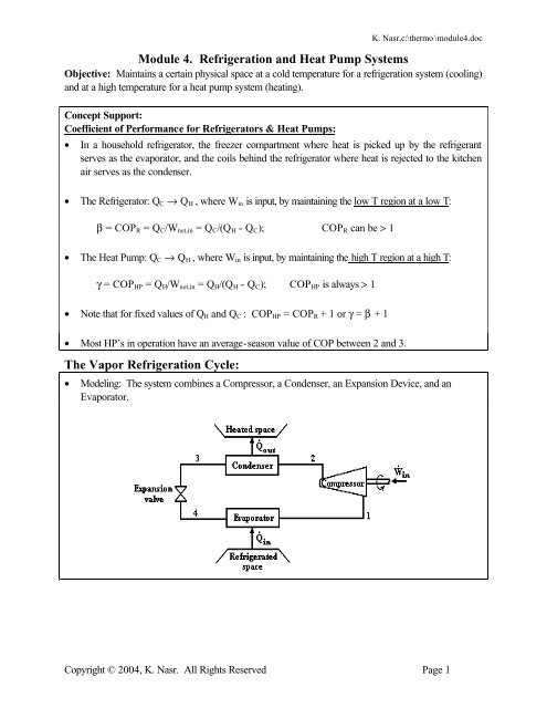
<strong>The</strong> <strong>Vapor</strong> <strong>Refrigeration</strong> Cycle:<br />
• Modeling: <strong>The</strong> system combines a Compressor, a Condenser, an Expansion Device, <strong>and</strong> an<br />
Evaporator.<br />
Copyright © 2004, K. Nasr. All Rights Reserved Page 1
K. Nasr,c:\thermo \module<strong>4.</strong>doc<br />
A Simplified <strong>Vapor</strong>-Compression <strong>Refrigeration</strong> Cycle (Carnot - left <strong>and</strong> Ideal - right)<br />
• <strong>Heat</strong> is transferred to the working fluid (refrigerant) in the evaporator <strong>and</strong> then compressed by the<br />
compressor. <strong>Heat</strong> is transferred from the working fluid in the condenser, <strong>and</strong> then its pressure is<br />
suddenly reduced in the expansion valve. A refrigeration cycle is used to extract energy from a fluid<br />
(air) in contact with the evaporator.<br />
• It’s normally assumed that kinetic <strong>and</strong> potential energy are negligible, <strong>and</strong> that the expansion process<br />
through the valve is a throttling process.<br />
¯<br />
Carnot Operation:<br />
1. Isentropic Compression<br />
2. Constant Pressure <strong>Heat</strong> Rejection<br />
3. Isentropic Expansion<br />
<strong>4.</strong> Constant Pressure <strong>Heat</strong> Absorption<br />
• A Carnot cycle is the most efficient, however it is not practical because:<br />
(I) <strong>The</strong> compressor would experience wear due to liquid droplets since state (1) is a liquid-vapor<br />
mixture.<br />
(II) It is difficult to maintain equilibrium between liquid <strong>and</strong> vapor if we do compress<br />
(III) the isentropic expansion device, involving no losses (friction), is expensive to construct.<br />
⊕<br />
Ideal Cycle Operation: Corrects for the drawbacks of Carnot operation by having:<br />
1. Inlet to compressor is saturated vapor<br />
2. exit of compressor is superheated vapor<br />
3. An irreversible throttling process as an expansion process.<br />
• <strong>The</strong> performance of the refrigeration cycle is quantified by the coefficient of performance:<br />
COP = Q evap . / W comp .<br />
¯ Applications of the Open System 1st <strong>and</strong> 2nd Laws to the Various Devices:<br />
• (1st Law): dE . . .<br />
2<br />
.<br />
2<br />
C.V.<br />
Vi<br />
Ve<br />
= QC.V.<br />
− WC V. . + ∑ m i(hi<br />
+ + gz<br />
i) − ∑ m e(he<br />
+ + gz<br />
e<br />
)<br />
dt<br />
2<br />
2<br />
• (2nd Law): dS dt<br />
QCV<br />
= + σ gen + mi<br />
si<br />
−<br />
T<br />
C. V. . .<br />
C. V.<br />
.<br />
i<br />
. . .<br />
∑ ∑ ∑<br />
i<br />
e<br />
me<br />
s<br />
e<br />
e<br />
Copyright © 2004, K. Nasr. All Rights Reserved Page 2
Assumptions: SSSF, Negligible ∆KE <strong>and</strong> ∆PE, Single-Inlet, Single-Outlet conditions<br />
K. Nasr,c:\thermo \module<strong>4.</strong>doc<br />
Process Device 1st Law 2nd Law<br />
.<br />
.<br />
1→2: Isentropic Compression Compressor<br />
WComp . = m(h1 − h<br />
2)<br />
s 2 = s 1<br />
.<br />
.<br />
2 →3: p = C. <strong>Heat</strong> Rejection Condenser<br />
QCond.<br />
= m(h3 − h<br />
2)<br />
s 2 > s 3<br />
3 →4: Adiabatic Throttling Throttling Device h 3 = h 4 s 4 > s 3<br />
(O-Tube, TXV)<br />
.<br />
.<br />
4 →1: p = C. <strong>Heat</strong> Absorption Evaporator<br />
Q = m(h − h )<br />
s 1 > s 4<br />
COP = Q Evap . / W Comp .<br />
Evap.<br />
1 4<br />
¯<br />
Actual Cycle Operation: Deviates from ideal cycle operation by having:<br />
1. Pressure drops due to friction in connecting pipes<br />
2. <strong>Heat</strong> transfer exists across connecting pipes<br />
3. Pressure drops occur through the condenser <strong>and</strong> evaporator tubes<br />
<strong>4.</strong> <strong>Heat</strong> transfer occurs from the compressor<br />
5. Frictional effects <strong>and</strong> flow separation occur on the compressor blades<br />
6. Refrigerant vapor entering the compressor may be slightly superheated<br />
7. Refrigerant temperature exiting the condenser may be slightly below saturation.<br />
A desirable effect out of the above list is item 7. Having a subcooled liquid exiting the<br />
condenser results in having a larger refrigeration effect.<br />
Problem:<br />
A vapor-compression refrigeration system for a household refrigerator has a refrigerating capacity of<br />
1000 Btu/h. <strong>The</strong> refrigerant, R134a, enters the evaporator at –10 °F <strong>and</strong> exits at 0 °F. <strong>The</strong> isentropic<br />
compressor efficiency is 80%. <strong>The</strong> refrigerant condenses at 95 °F <strong>and</strong> exits the condenser subcooled<br />
at 90 °F. <strong>The</strong>re are no significant pressure drops in the flows through the evaporator <strong>and</strong> condenser.<br />
We want to determine the evaporator <strong>and</strong> condenser pressures, the mass flow rate of the refrigerant,<br />
the compressor power input, <strong>and</strong> the coefficient of performance.<br />
Solution:<br />
• First, the refrigerating capacity is the rate of heat transfer into the refrigerant flowing in the<br />
evaporator. It is the cooling effect, that is the rate of heat transfer extracted from air on the outside<br />
of the evaporator. <strong>The</strong> refrigerating capacity is normally given in tons of refrigeration for a system<br />
where one ton of refrigeration is equivalent to 12000 Btu/hr.<br />
• Second, since the inlet to the evaporator is always a mixture of liquid <strong>and</strong> vapor, the pressure<br />
therefore is the saturation pressure at the given temperature. It is also assumed that frictional effects,<br />
between the refrigerant <strong>and</strong> the tubes of the evaporator, are neglected so that the pressure at the<br />
inlet equals the pressure at the exit of the evaporator.<br />
Copyright © 2004, K. Nasr. All Rights Reserved Page 3
K. Nasr,c:\thermo \module<strong>4.</strong>doc<br />
• Third, since the refrigerant condenses inside the condenser at 95 °F, then the pressure in the<br />
condenser is the saturation pressure at the given temperature.<br />
• Let’s determine the properties of R134a at each state to give us a better look at what the system is<br />
doing.<br />
lbf<br />
Interpolatedfrom TableA-12E<br />
State 1:<br />
Btu<br />
1<br />
= PSat@<br />
−10º<br />
F<br />
= 16.674 ⇒T1<br />
= 0º F ⎯⎯ ⎯⎯⎯⎯⎯⎯→h1<br />
= 102.2 , s<br />
lbm 1<br />
= 0. 2281<br />
2<br />
Btu<br />
P<br />
lbm*<br />
R<br />
in<br />
State 2:<br />
lbf InterpolatingfromTableA-12E<br />
Btu<br />
P Btu<br />
2<br />
= PSat@95º<br />
F<br />
= 128.62 ⎯⎯ ⎯⎯⎯⎯⎯⎯ →h2s<br />
= 121.01 , s<br />
lbm 2s<br />
= s1<br />
= 0. 2281<br />
lbm*<br />
R<br />
in2<br />
Utilizing the concept for the isentropic efficiency of a compressor, being the ratio of the isentropic<br />
(minimum required) to the actual power, we get the actual enthalpy value of the refrigerant leaving the<br />
compressor:<br />
η<br />
C<br />
h<br />
=<br />
h<br />
2s<br />
2a<br />
− h<br />
1<br />
− h<br />
1<br />
⇒ h<br />
2a<br />
= h<br />
1<br />
+<br />
h<br />
2s<br />
η<br />
− h<br />
C<br />
1<br />
= 125.7<br />
Btu<br />
lbm<br />
State 3:<br />
T 40. 72<br />
3<br />
= 90 F ( subcooled ) ⇒ h3<br />
= h f<br />
+ vf<br />
(P - Psat<br />
) =<br />
Btu<br />
lbm<br />
State 4: (3) to (4) is a throttling process, thus from the 1 st Btu<br />
law: h3 = h4<br />
= 40. 72<br />
lbm<br />
• To determine the mass flow rate, we need to utilize the refrigeration capacity,<br />
enthalpies at State 4 <strong>and</strong> 1.<br />
Q&<br />
⎛ 1000 Btu ⎞<br />
In<br />
h<br />
1h<br />
lbm<br />
m & = = ⎜<br />
⎟ = 0.271<br />
Btu<br />
min<br />
h1<br />
− h<br />
4<br />
( 102.2 40.72) ⎝ − 60 min<br />
lbm ⎠<br />
Q &<br />
In<br />
<strong>and</strong> the specific<br />
• Now we can calculate the power needed, in horsepower, to run the compressor via the 1 st Law:<br />
60 min ⎛ 1hp<br />
⎞<br />
W&<br />
lbm<br />
Btu ⎛ ⎞<br />
C = m&<br />
( h1 − h2<br />
) = ( 0.271<br />
)( 102.2 125.7) min<br />
−<br />
lbm ⎜ ⎟⎜<br />
⎟ = −0.<br />
150hp<br />
Btu<br />
⎝ 1h<br />
⎠<br />
2545<br />
⎝ h ⎠<br />
• Its performance is measured via Coefficient of Performance (COP).<br />
• Now we can determine the coefficient of performance for this refrigerator. It has the same notion as<br />
the efficiency. In this case, “what I get” is cooling off the evaporator <strong>and</strong> “what I pay for” is<br />
compressor power. <strong>The</strong>refore,<br />
h<br />
β =<br />
h<br />
1<br />
2<br />
− h<br />
4<br />
− h<br />
1<br />
= 2.62<br />
Copyright © 2004, K. Nasr. All Rights Reserved Page 4
K. Nasr,c:\thermo \module<strong>4.</strong>doc<br />
Other Questions for Critical Thinking:<br />
What is the rate of heat rejection on the condenser side?<br />
Is energy Conserved for this cyclic device?<br />
What is the entropy change for the refrigerant flowing through the compressor?<br />
What is the entropy change for the refrigerant flowing through the condenser?<br />
What is the entropy change for the refrigerant flowing through the expansion valve?<br />
What is the entropy change for the refrigerant flowing through the evaporator?<br />
Copyright © 2004, K. Nasr. All Rights Reserved Page 5
K. Nasr,c:\thermo \module<strong>4.</strong>doc<br />
If the air around the condenser experiences a temperature rise of 15 °F, what is the mass flow rate<br />
of air via a fan across the condenser’s coils?<br />
Estimate the CFM (ft 3 /min) of air flowing across the condenser coils<br />
Can you draw a T-s diagram <strong>and</strong> trace the refrigerant as it goes through from device to device?<br />
Can you draw an pressure –enthalpy (p-h) diagram as this is what was normally used to get<br />
enthalpy values prior to the days of computers <strong>and</strong> tables?<br />
HW # 13<br />
Due Tuesday of 10 th Week<br />
• Generate a concept map for this module <strong>and</strong> e-mail to me electronically<br />
• Problem <strong>4.</strong>84 of your textbook<br />
• Problem 10.17 (a), (b) of your textbook<br />
• Problem 10.41 (a), (b) of your textbook<br />
You may find examples 10.1, 10.2, 10.3 of your textbook to be quite useful<br />
Corresponding Coverage in your text book:<br />
Chapter 10. <strong>Refrigeration</strong> <strong>and</strong> <strong>Heat</strong> pump <strong>Systems</strong><br />
Section 10.1. <strong>Vapor</strong> <strong>Refrigeration</strong> <strong>Systems</strong><br />
Section 10.2. Analyzing <strong>Vapor</strong>-Compression <strong>Refrigeration</strong> <strong>Systems</strong>.<br />
Section 10.3. Refrigerant Properties.<br />
Copyright © 2004, K. Nasr. All Rights Reserved Page 6