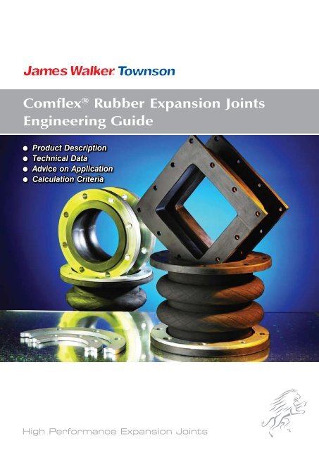
Comflex® Rubber Expansion Joints Engineering Guide
Comflex® Rubber Expansion Joints Engineering Guide
Comflex® Rubber Expansion Joints Engineering Guide

You also want an ePaper? Increase the reach of your titles
YUMPU automatically turns print PDFs into web optimized ePapers that Google loves.
Comflex ® <strong>Rubber</strong> <strong>Expansion</strong> <strong>Joints</strong><br />
<strong>Engineering</strong> <strong>Guide</strong><br />
● Product Description<br />
● Technical Data<br />
● Advice on Application<br />
● Calculation Criteria<br />
High Performance <strong>Expansion</strong> <strong>Joints</strong>
Comflex ® <strong>Rubber</strong> <strong>Expansion</strong> <strong>Joints</strong><br />
Contents<br />
<strong>Engineering</strong> <strong>Guide</strong><br />
Summary of Comflex ® <strong>Expansion</strong> <strong>Joints</strong> 3<br />
Bellows Construction 4<br />
<strong>Rubber</strong> qualities, reinforcing materials and max. application range<br />
for various bellows types<br />
Material Description 5<br />
Comflex ® <strong>Expansion</strong> <strong>Joints</strong> 6<br />
Type 39 6<br />
Type 40 8<br />
Type 42 14<br />
Type 45 16<br />
Type 46 17<br />
Type 48 19<br />
Type 49 20<br />
Type 50 24<br />
Type 51 29<br />
Type 53 30<br />
Type 54 31<br />
Type 55 32<br />
Type 56 34<br />
Type 57 35<br />
Type 58 37<br />
Type 59 38<br />
Type 60 39<br />
Type 61 40<br />
Type 62 41<br />
Type 63 42<br />
Type 64 43<br />
Type 80 45<br />
Tie Bars / Restraints 48<br />
Special Parts 50<br />
Flameproof protective covers, deflector sleeve, earth cover, safety, pressure balanced<br />
Planning, Installation and Maintenance Instructions 52<br />
for Types 39, 45, 46, 48, 49, 50, 51, 53, 54, 55, 56, 57<br />
Installation and Maintenance for all Solid Flanges 57<br />
for Types 40, 42, 58, 59, 63<br />
Flange Bolt Torques (Nm)<br />
for Types 40, 42, 58, 59, 63 59<br />
Installation and Maintenance Instructions for Type 64 61<br />
Installation Instructions for Type 80 62<br />
Sealing Profile of the <strong>Rubber</strong> Bellows 63<br />
Mating Flange Dimensions 64<br />
Additional Comflex ® <strong>Expansion</strong> <strong>Joints</strong> 65<br />
Technical <strong>Guide</strong>s and Data Sheets 66<br />
2<br />
To order or get further details, call your local contact shown on rear cover or listed at www.jameswalker.biz
Summary of Comflex ® <strong>Expansion</strong> <strong>Joints</strong><br />
Type<br />
55<br />
DN-range 32 - 1000<br />
Overall length (mm) 125 - 300<br />
Type<br />
39<br />
Type<br />
40<br />
Type<br />
42<br />
Type<br />
45<br />
Type<br />
46<br />
DN-range 50 - 1000<br />
Overall length (mm) variable<br />
Fields of Application<br />
Shipbuilding, Industrial Plants,<br />
Repair/Substitute<br />
DN-range 200 - 5000<br />
Overall length (mm) 200 - 450<br />
Fields of Application<br />
Power Stations, Commercial<br />
Plants, Purification Plants,<br />
Pipelines<br />
DN-range 50 - 4000<br />
Overall length (mm) 145 - 450<br />
Fields of Application<br />
Shipbuilding, Paper Industry,<br />
Hydraulic Systems, Power<br />
Stations<br />
DN-Range 20 - 50<br />
Overall length (mm) 120 - 155<br />
Fields of Application<br />
Housing Technology, Motor<br />
Technology, Air Conditioning<br />
System, Sprinkler System<br />
DN-range 20 - 50<br />
Overall length (mm) 130<br />
Fields of Application,<br />
Housing Technology,<br />
Motor Technology<br />
Type<br />
56<br />
Type<br />
57<br />
Type<br />
58<br />
Type<br />
59<br />
Fields of Application<br />
Shipbuilding, Housing<br />
Technology, Waterworks and<br />
Purification Plants<br />
DN-range 20 - 300<br />
Overall length (mm) 100 - 1000<br />
Fields of Application<br />
Shipbuilding, Paper Industry,<br />
Material Handling Technology,<br />
Media Particles Solution<br />
DN-range 20 - 300<br />
Overall length (mm) 250/300<br />
Fields of Application<br />
Shipbuilding, Paper Industry,<br />
Material Handling Technology,<br />
Media Particles Solution<br />
DN-range 40 - 3000<br />
Overall length (mm) 250 - 1000<br />
Fields of Application<br />
Shipbuilding, Paper Industry,<br />
Material Handling Technology,<br />
Media Particles Solution<br />
DN-range 100 - 3000<br />
Overall length (mm) 250/300<br />
Fields of Application<br />
Shipbuilding, Paper Industry,<br />
Material Handling Technology,<br />
Media Particles Solution<br />
Type<br />
48<br />
Type<br />
49<br />
Type<br />
50<br />
Type<br />
51<br />
DN-range 50 - 250<br />
Overall length (mm) 150 - 170<br />
Fields of Application<br />
Steel works, Shipbuilding,<br />
Plant Construction<br />
DN-range 32 - 500<br />
Overall length (mm) 100/110<br />
Fields of Application<br />
Housing Technology,<br />
Shipbuilding, Plant<br />
Construction, Gas Plants<br />
Scales Technology<br />
DN-range 20 - 1000<br />
Overall length (mm) 130/300<br />
Fields of Application<br />
Plant Construction, Gas Plants,<br />
Housing Technology, Power<br />
Stations<br />
DN-range 50 - 600<br />
Overall length (mm) 130/250<br />
Fields of Application<br />
Chemical Plants<br />
Type<br />
60<br />
Type<br />
61<br />
Type<br />
62<br />
Type<br />
63<br />
DN-range 20 - 200<br />
Overall length (mm) 70/90<br />
Fields of Application<br />
Housing Technology,<br />
Industrial Plants<br />
DN-range 50 - 1000<br />
Overall length (mm) 250<br />
Fields of Application<br />
Industrial Plants,<br />
Motor Technology,<br />
Sewage Technology<br />
DN-range 70 - 1000<br />
Overall length (mm) variable<br />
Fields of Application<br />
Drainage Systems for Bridges,<br />
Large Buildings<br />
DN-range<br />
Overall length (mm)<br />
all<br />
variable<br />
Fields of Application<br />
Special hand-formed items,<br />
Plant construction/Wall seals<br />
Type<br />
53<br />
DN-range 20 - 300<br />
Overall length (mm) 130<br />
Type<br />
64<br />
DN-range<br />
Overall length (mm)<br />
all<br />
variable<br />
Fields of Application<br />
Plant constructions, Housing<br />
Technology, Waterworks and<br />
Purification Plants<br />
Fields of Application<br />
Motor Technology, Sewage<br />
Technology, Air Construction,<br />
Plant construction/Wall seals<br />
Type<br />
54<br />
DN-range 32 - 125<br />
Overall length (mm) 65 - 130<br />
Type<br />
80<br />
DN-range 20 - 1200<br />
Overall length (mm) 50 - 170<br />
Fields of Application<br />
Hydraulic System<br />
Fields of Application<br />
Chemical Plants<br />
To order or get further details, call your local contact 3shown on rear cover or listed at www.jameswalker.biz 3
Bellows Construction<br />
Core<br />
(inner)<br />
Bellows design<br />
Reinforcing<br />
material<br />
Cover<br />
(outer)<br />
Bellows<br />
colour<br />
code<br />
Type<br />
39<br />
Type<br />
40<br />
Type<br />
42<br />
Type<br />
45<br />
Type<br />
46<br />
max. pressure / max. permissible temperature (bar/°C)<br />
Type<br />
48<br />
Type<br />
49<br />
Type<br />
50<br />
Type<br />
51<br />
Type<br />
53<br />
Type<br />
54<br />
Type<br />
55<br />
EPDM<br />
Aramid/<br />
Special cord<br />
EPDM<br />
red-red<br />
25/130<br />
27/130<br />
80/130<br />
/<br />
16/100<br />
16/110<br />
25/110<br />
16/110<br />
/<br />
/<br />
/<br />
16/110<br />
6/120<br />
EPDM Nylon cord EPDM red 16/90 18/90 16/90 10/90 16/90 16/90 25/90 / / 16/90 / 16/90 10/90<br />
EPDM Steel cord EPDM red-red-blue 16/130 / 16/130 / 16/110 / / / / / / / /<br />
NBR<br />
Aramid/<br />
Special cord<br />
NBR<br />
yellow-blue<br />
25/120<br />
27/100<br />
80/120<br />
/<br />
/<br />
/<br />
/<br />
/<br />
/<br />
25/120<br />
/<br />
/<br />
6/120<br />
NBR<br />
Nylon cord<br />
Chloroprene<br />
CR<br />
yellow<br />
16/80<br />
18/80<br />
16/80<br />
/<br />
16/90<br />
/<br />
25/90<br />
16/90<br />
/<br />
16/90<br />
10/90<br />
16/90<br />
10/90<br />
NBR Nylon cord Chloroprene<br />
CR<br />
orange<br />
/<br />
18/90<br />
/<br />
/<br />
16/90<br />
/<br />
/<br />
25/90<br />
/<br />
/<br />
/<br />
/<br />
/<br />
NBR<br />
Steel cord<br />
Chloroprene<br />
CR<br />
yellow-yellow<br />
16/120<br />
/<br />
/<br />
/<br />
16/100<br />
/<br />
/<br />
16/100<br />
/<br />
/<br />
/<br />
16/100<br />
/<br />
Hypalon ®<br />
CSM<br />
Aramid/<br />
Special cord<br />
Hypalon ®<br />
CSM<br />
green-blue<br />
25/120<br />
27/130<br />
80/120<br />
/<br />
/<br />
/<br />
/<br />
/<br />
/<br />
16/120<br />
/<br />
/<br />
10/120<br />
Hypalon ®<br />
CSM<br />
Nylon cord<br />
Hypalon ®<br />
CSM<br />
green<br />
16/80<br />
18/80<br />
16/80<br />
/<br />
16/90<br />
/<br />
25/80<br />
16/80<br />
/<br />
/<br />
/<br />
16/80<br />
10/90<br />
Chloroprene<br />
CR<br />
Nylon cord<br />
Chloroprene<br />
CR<br />
grey<br />
/<br />
18/80<br />
16/80<br />
/<br />
16/80<br />
16/80<br />
/<br />
16/70<br />
/<br />
16/70<br />
/<br />
/<br />
10/70<br />
Butyl<br />
IIR<br />
Nylon cord<br />
EPDM<br />
red-blue<br />
16/90<br />
18/90<br />
16/90<br />
/<br />
16/90<br />
/<br />
25/90<br />
16/90<br />
/<br />
/<br />
/<br />
16/90<br />
/<br />
Butyl<br />
IIR-D<br />
Aramid/<br />
Special cord<br />
EPDM<br />
red-blue<br />
25/150<br />
/<br />
80/150<br />
/<br />
/<br />
/<br />
/<br />
/<br />
/<br />
25/150<br />
/<br />
/<br />
6/150<br />
Viton ®<br />
FKM<br />
Aramid/<br />
Special cord<br />
Chloroprene<br />
CR<br />
lilac<br />
25/120<br />
/<br />
80/120<br />
/<br />
/<br />
/<br />
/<br />
/<br />
25/120<br />
/<br />
/<br />
/<br />
/<br />
Viton ®<br />
FKM<br />
Aramid/<br />
Special cord<br />
EPDM<br />
lilac-red<br />
25/150<br />
27/150<br />
80/150<br />
/<br />
/<br />
/<br />
/<br />
/<br />
25/150<br />
/<br />
/<br />
/<br />
6/120<br />
Viton ®<br />
FKM<br />
Aramid/<br />
Special cord<br />
Viton ®<br />
FKM<br />
lilac-lilac<br />
/<br />
/<br />
/<br />
/<br />
/<br />
/<br />
/<br />
/<br />
/<br />
/<br />
/<br />
/<br />
/<br />
Aramid/<br />
Special cord<br />
SIL<br />
/<br />
/<br />
27/150<br />
/<br />
/<br />
/<br />
/<br />
/<br />
/<br />
/<br />
/<br />
/<br />
/<br />
/<br />
Special manufacture for higher pressure and temperature is available on request.<br />
Important: Quoted values are max. values. The quoted pressures are valid at 50°C a decrease relative to increasing temperatures.<br />
Please contact James Walker Townson for resistance at specific temperatures.<br />
Type<br />
60<br />
10/110<br />
/<br />
/<br />
/<br />
/<br />
/<br />
/<br />
/<br />
/<br />
/<br />
/<br />
/<br />
/<br />
/<br />
/<br />
/<br />
Type<br />
61<br />
6/110<br />
6/90<br />
/<br />
/<br />
6/90<br />
/<br />
/<br />
/<br />
6/90<br />
/<br />
/<br />
/<br />
6/100<br />
/<br />
/<br />
/<br />
Type<br />
62<br />
/<br />
3/90<br />
/<br />
/<br />
3/90<br />
/<br />
/<br />
/<br />
3/90<br />
3/70<br />
/<br />
/<br />
/<br />
/<br />
/<br />
/<br />
Type<br />
63<br />
6/110<br />
6/90<br />
/<br />
/<br />
6/90<br />
/<br />
/<br />
6/120<br />
6/90<br />
/<br />
6/90<br />
/<br />
6/120<br />
/<br />
/<br />
6/200<br />
Type<br />
64<br />
/<br />
0.5/120<br />
/<br />
/<br />
0.4/100<br />
/<br />
/<br />
/<br />
/<br />
/<br />
/<br />
/<br />
/<br />
/<br />
0.5/200<br />
0.2/200<br />
4<br />
To order or get further details, call your local contact shown on rear cover or listed at www.jameswalker.biz
Material Description<br />
Abbreviation<br />
(colour code)<br />
Name<br />
Properties<br />
EPDM Ethylene- Good heat resistance and suitable for alkaline waste water, compressed air<br />
propylene terpolymer (oil free) and chemicals, weather-resistant, good gas tightness<br />
red<br />
terpolymer except for hydrocarbon.<br />
Temperature range -35°C up to +130°C<br />
Not suitable for oils or fatty media.<br />
NBR Acryonitrile Oil and fuel quality, also suitable for gases, solvents and fats.<br />
butadiene High abrasion resistance.<br />
yellow<br />
rubber<br />
Temperature range -20°C up to +90°C (120°C)<br />
Not suitable for steam and hot water.<br />
NBR Acryonitrile Oil and fuel quality, also suitable for gases, solvents and fats and<br />
butadiene LPG acc. to DIN 51622. High abrasion resistance.<br />
rubber<br />
Temperature range -30°C up to +90°C<br />
orange<br />
Not suitable for steam and hot water.<br />
NBR Acryonitrile Foodstuff quality in accordance with RAL guidelines, good for pulps,<br />
butadiene fats, flours, juices and wines.<br />
white<br />
rubber<br />
Temperature range -20°C up to +90°C<br />
Hypalon ® CSM Chloro- Chemical resistant quality for acids, bases and lyes.<br />
sulfonated Temperature range -20°C up to +130°C<br />
polyethylene See resistance lists for specific temperatures.<br />
green<br />
Neoprene CR Chloroprene Water quality, weather-resistant, suitable for some small groups of lyes as well as<br />
rubber<br />
compressed air and lightly oil-related media.<br />
grey<br />
Temperature range -25°C up to +90°C<br />
SIL Silicone Suitable for diluted hydrochloric acids, animal and herbal oils and fats,<br />
rubber<br />
Hydraulic fluids (HFD-R and HFD-S)<br />
Temperature range -40°C up to +200°C<br />
none<br />
Butyl IIR Butyl Good heat resistance, suitable for alkaline waste water, compressed air (oil free),<br />
red or blue<br />
rubber<br />
chemicals and special hydraulic oils, weather-resistant.<br />
Temperature range -30°C up to +90°C<br />
Drinking water quality in accordance with KTW-<strong>Guide</strong>lines.<br />
Butyl IIR-D Butyl Good heat resistance, suitable for alkaline waste water, compressed air (oil free),<br />
rubber<br />
chemicals and special hydraulic oils, weather-resistant.<br />
red/blue<br />
Temperature range -25°C up to +150°C<br />
Viton ® FKM Fluorocarbon Particularly suited to high temperatures.<br />
polymer Good resistance to chemicals and oils, combustibles and solvents.<br />
lilac<br />
Temperature range -20°C up to +180°C<br />
Not suitable for ketones and chlorine.<br />
PTFE Polytetrafluoro- Resistant to most media.<br />
none<br />
ethylene Temperature range -50°C up to +230°C<br />
Not suitable for alkali metals in molten state and<br />
reaction-formed amides.<br />
The indicated temperatures relate to flexible applications. In rigid applications lower temperatures can be used.<br />
For pressure and expansion details please refer to the type descriptions.<br />
For chemical resistance please contact James Walker Townson.<br />
To order or get further details, call your local contact 5shown on rear cover or listed at www.jameswalker.biz 5
James Walker Townson <strong>Rubber</strong> Comflex ®<br />
<strong>Expansion</strong> Joint Type 39 TYPE 39<br />
Type 39 is a hand-built low corrugated rubber Comflex ® <strong>Expansion</strong><br />
Joint and can therefore be customised to fit in any existing gap by<br />
virtue of its variable overall length.<br />
Design:<br />
Low corrugated rubber bellows with reinforcing inserts and<br />
built-in packing profile for absorption of the swivel flanges.<br />
The expansion joint is self-sealing, no additional gaskets<br />
are required.<br />
Characteristics for type 39<br />
Bellows<br />
colour code<br />
Core<br />
(inner)<br />
Bellows design<br />
Reinforcing<br />
material<br />
Cover<br />
(outer)<br />
Permissible operating data<br />
bar °C<br />
bar °C<br />
Electrical<br />
resistance<br />
bar °C Ohm cm<br />
Hardness<br />
shore A<br />
red-St<br />
EPDM<br />
Steel cord<br />
EPDM<br />
16 50<br />
10 100<br />
6 130<br />
7 x 10 2<br />
60<br />
red<br />
EPDM<br />
Nylon cord<br />
EPDM<br />
16 50<br />
10 70<br />
8 90<br />
7 x 10 2<br />
60<br />
yellow-St<br />
NBR<br />
Steel cord<br />
CR<br />
16 50<br />
12 70<br />
10 100<br />
5 x 10 3<br />
60<br />
yellow<br />
NBR<br />
Nylon cord<br />
CR<br />
10 50<br />
10 70<br />
10 90<br />
5 x 10 3<br />
60<br />
green-St<br />
CSM<br />
Steel cord<br />
CSM<br />
16 50<br />
12 70<br />
10 90<br />
4 x 10 10<br />
65<br />
green<br />
CSM<br />
Nylon cord<br />
CSM<br />
10 50<br />
10 70<br />
10 90<br />
4 x 10 10<br />
65<br />
white<br />
NBR/white<br />
Nylon cord<br />
CR<br />
10 50<br />
10 70<br />
10 80<br />
5 x 10 3<br />
60<br />
lilac<br />
FKM<br />
Aramid<br />
EPDM<br />
16 50<br />
10 130<br />
4 150<br />
65<br />
Burst pressure > 3 x max. bar<br />
Suitable for vacuum up to 0.8 bar abs., without supporting ring<br />
Suitable for vacuum up to 0 bar abs., with supporting ring<br />
Vacuum supporting rings<br />
James Walker Townson type 39 expansion joints are<br />
vacuum- resistant. To prevent the expansion joint<br />
bellows being drawn together by suction at negative<br />
pressure, the insertion of a vacuum supporting ring<br />
is necessary for a suction value above 2 m (0.8 bar<br />
abs., 20% negative pressure).<br />
Type A<br />
Flanges: (Design A)<br />
Swivel flanges both sides (Design A) with integral rubber<br />
profile, so that additional gaskets are not required (selfsealing).<br />
The flanges are drilled to DIN PN 10 as standard. Other<br />
specifications in accordance with DIN, ASA, BS and<br />
special flanges are also available.<br />
Flange Material: Standard S 235 JRG2 (RSt 37-2) zinc<br />
plated and yellow passivated. Other materials available<br />
on request.<br />
Note:<br />
For aggressive media please refer to the resistance<br />
table. The bellows must not be painted or insulated.<br />
Further installation advices in appendix.<br />
Accessories:<br />
Tie bar/Restraints See page 48<br />
Deflector sleeve See page 50<br />
Flameproof protective cover See page 50<br />
Earth cover See page 51<br />
6<br />
To order or get further details, call your local contact shown on rear cover or listed at www.jameswalker.biz
Application:<br />
TYPE 39<br />
Type 39 For drinking water / hot water<br />
red For cold and hot water, also with the addition of<br />
chemicals for water treatment. Industrial water, acids,<br />
lyes, alcohols, esters and ketones.<br />
Not suitable for oil-related media.<br />
Type 39 For the food and beverage industry<br />
white Also suitable for oil- and fat-containing foodstuff.<br />
Type 39 For chemical plants<br />
green For heavy chemical use. Permissible temperature, working<br />
pressure and life expectancy depend on the medium and<br />
its concentration in each case.<br />
Type 39 For oil, fuel, gas<br />
yellow Application range: Town and natural gas, blast furnace<br />
gas, fuel, lube oil, heating oil, cooling water emulsion<br />
Type 39 For chemical plants<br />
lilac Particularly for higher thermal duty up to approx. 150°C.<br />
The highest permissible load depends on a mixture of<br />
temperature, pressure, movement and life expectancy.<br />
DN<br />
50<br />
65<br />
80<br />
100<br />
125<br />
150<br />
200<br />
250<br />
300<br />
350<br />
400<br />
450<br />
500<br />
600<br />
700<br />
750<br />
800<br />
900<br />
1000<br />
Overall length Bellows<br />
ØA Effect. ØD<br />
surface<br />
mm mm cm 2 mm<br />
130 - 500<br />
130 - 500<br />
130 - 500<br />
130 - 500<br />
130 - 500<br />
130 - 500<br />
130 - 500<br />
130 - 500<br />
130 - 500<br />
130 - 500<br />
150 - 500<br />
150 - 500<br />
150 - 500<br />
150 - 500<br />
150 - 500<br />
150 - 500<br />
150 - 500<br />
150 - 500<br />
150 - 500<br />
96<br />
110<br />
122<br />
142<br />
170<br />
196<br />
256<br />
306<br />
352<br />
442<br />
495<br />
545<br />
595<br />
695<br />
832<br />
882<br />
932<br />
1032<br />
1134<br />
32<br />
53<br />
85<br />
128<br />
187<br />
259<br />
409<br />
599<br />
822<br />
1080<br />
1379<br />
1801<br />
2038<br />
3286<br />
4183<br />
4751<br />
5407<br />
6706<br />
8231<br />
165<br />
185<br />
200<br />
220<br />
250<br />
285<br />
340<br />
395<br />
445<br />
505<br />
565<br />
615<br />
670<br />
780<br />
895<br />
-<br />
1015<br />
1115<br />
1230<br />
Flange PN 10<br />
125<br />
145<br />
160<br />
180<br />
210<br />
240<br />
295<br />
350<br />
400<br />
460<br />
515<br />
565<br />
620<br />
725<br />
840<br />
-<br />
950<br />
1050<br />
1160<br />
18<br />
18<br />
18<br />
18<br />
18<br />
23<br />
23<br />
23<br />
23<br />
22<br />
26<br />
26<br />
26<br />
30<br />
30<br />
-<br />
33<br />
33<br />
36<br />
4<br />
4<br />
8<br />
8<br />
8<br />
8<br />
8<br />
12<br />
12<br />
16<br />
16<br />
20<br />
20<br />
20<br />
24<br />
-<br />
24<br />
28<br />
28<br />
16<br />
16<br />
18<br />
18<br />
18<br />
20<br />
20<br />
20<br />
20<br />
20<br />
25<br />
25<br />
30<br />
30<br />
35<br />
35<br />
40<br />
40<br />
40<br />
Movement absorption<br />
ØPC Ød n s axial lat. ∠° ØC<br />
+ - +/-<br />
mm mm mm mm mm mm +/- mm<br />
10<br />
10<br />
15<br />
15<br />
15<br />
15<br />
15<br />
15<br />
15<br />
15<br />
20<br />
20<br />
20<br />
20<br />
20<br />
20<br />
20<br />
20<br />
20<br />
20<br />
20<br />
20<br />
20<br />
20<br />
20<br />
20<br />
20<br />
20<br />
20<br />
25<br />
25<br />
25<br />
25<br />
25<br />
25<br />
25<br />
25<br />
25<br />
15<br />
15<br />
15<br />
15<br />
15<br />
15<br />
15<br />
15<br />
15<br />
15<br />
20<br />
20<br />
20<br />
20<br />
20<br />
20<br />
20<br />
20<br />
20<br />
35<br />
30<br />
30<br />
25<br />
25<br />
20<br />
15<br />
10<br />
10<br />
10<br />
8<br />
8<br />
6<br />
6<br />
5<br />
4<br />
4<br />
4<br />
4<br />
89<br />
104<br />
119<br />
142<br />
169<br />
195<br />
245<br />
295<br />
348<br />
412<br />
470<br />
512<br />
570<br />
675<br />
780<br />
830<br />
887<br />
985<br />
1085<br />
Permissible % of indicated movement relative to temperature:<br />
up to 50°C ~ 100%<br />
up to 70°C ~ 75%<br />
up to 90°C ~ 60%<br />
Tie bar and flange design see Annex page 48<br />
To order or get further details, call your local contact 7shown on rear cover or listed at www.jameswalker.biz 7
James Walker Townson <strong>Rubber</strong> Comflex ® <strong>Expansion</strong><br />
Joint Type 40<br />
Type 40 incorporates a highly flexible convolution with solid rubber<br />
flanges. It is characterized by its ability to compensate for high<br />
movement and its low inherent resistance.<br />
TYPE 40<br />
Design:<br />
High corrugated rubber bellows body with reinforcing inserts and<br />
integral pressure-strengthened solid rubber flanges, self-sealing,<br />
requiring no additional gaskets. One-piece steel backing flanges,<br />
with supporting collar, to ensure the smooth rolling up of the bellows.<br />
Application:<br />
Cooling water piping in power stations and industrial plant, desalination<br />
plants, drinking water supply, shipbuilding and in pumps, turbines<br />
and tanks, for the absorption of movements, oscillations, noise<br />
and vibrations, as well as being installed as an axial and lateral<br />
expansion joint for building settlement.<br />
Max. DN 5000<br />
Flange:<br />
Standard design acc. to DIN PN 10, retaining flange in S 235 JRG2 (RSt.<br />
37-2) hot-dip galvanized. Other materials and drillings are<br />
possible on request.<br />
Overall lengths:<br />
The indicated overall lengths are standard lengths and can be altered<br />
(multi-corrugated design for higher expansion compensation possible).<br />
Details for type 40<br />
Bellows<br />
identification<br />
marking<br />
Core<br />
Reinforcing material<br />
Cover<br />
Pressure<br />
(max.) bar<br />
Temperature<br />
(max.) °C<br />
red<br />
red/red<br />
blue<br />
white<br />
grey<br />
green<br />
green/red<br />
yellow<br />
yellow/red<br />
yellow/yellow<br />
lilac<br />
lilac<br />
Nylon cord<br />
Aramid<br />
Nylon cord<br />
Nylon cord<br />
Nylon cord<br />
Nylon cord<br />
Aramid<br />
Nylon cord<br />
Aramid<br />
Aramid<br />
Nylon cord<br />
Aramid<br />
Glass Fibre<br />
Aramid<br />
18<br />
27<br />
18<br />
18<br />
18<br />
18<br />
27<br />
18<br />
27<br />
27<br />
18<br />
27<br />
3<br />
27<br />
90<br />
130<br />
90<br />
90<br />
70<br />
90<br />
130<br />
90<br />
100<br />
130<br />
90<br />
150<br />
200<br />
150<br />
The pressure indication states a max. value which depends on the lengths and nominal widths (see chart page 9 and 10) burst pressure >50 bar.<br />
All Comflex ® <strong>Expansion</strong> <strong>Joints</strong> can be delivered with a compensation of potential. Suitable for vacuum up to 0.8 bar abs., without supporting ring (2m suction<br />
height). Suitable for vacuum up to 0 bar abs., with supporting ring (10m suction height). The bellows can be manufactured with vulcanized PTFE foil to achieve a<br />
higher chemical resistance. On request vacuum rings can be vulcanized in the bellows (no vacuum or medium contact). Flange connections will be manufactured<br />
on request in all versions, e.g. PN6, PN10, PN16, ANSI B 16.5 class 150, ANSI B 16.47 class 150.<br />
The steel retaining flanges will be designed according to the pressure with or without supporting collar. The preloading flanges will be calculated according to the<br />
operating pressure (versions see page 48 and 49).<br />
8<br />
To order or get further details, call your local contact shown on rear cover or listed at www.jameswalker.biz
9<br />
To order or get further details, call your local contact shown on rear cover or listed at www.jameswalker.biz 9<br />
200<br />
250<br />
300<br />
350<br />
400<br />
450<br />
500<br />
550<br />
600<br />
650<br />
700<br />
750<br />
800<br />
850<br />
900<br />
950<br />
1000<br />
1050<br />
1100<br />
1150<br />
1200<br />
1250<br />
1300<br />
1350<br />
1400<br />
1450<br />
1500<br />
1600<br />
1650<br />
1700<br />
1800<br />
1950<br />
2000<br />
2100<br />
2150<br />
2200<br />
2250<br />
2300<br />
2400<br />
2500<br />
2550<br />
2600<br />
2700<br />
2800<br />
2850<br />
2900<br />
3000<br />
150<br />
150<br />
150<br />
150<br />
200<br />
200<br />
200<br />
200<br />
200<br />
200<br />
200<br />
200<br />
250<br />
250<br />
250<br />
250<br />
250<br />
250<br />
300<br />
300<br />
300<br />
300<br />
300<br />
300<br />
300<br />
300<br />
300<br />
300<br />
300<br />
300<br />
300<br />
300<br />
300<br />
300<br />
300<br />
300<br />
300<br />
300<br />
300<br />
300<br />
300<br />
300<br />
300<br />
300<br />
300<br />
300<br />
300<br />
504<br />
717<br />
977<br />
1223<br />
1733<br />
2119<br />
2535<br />
2988<br />
3479<br />
3974<br />
4584<br />
5137<br />
5867<br />
6478<br />
7265<br />
7942<br />
8812<br />
9556<br />
11045<br />
11877<br />
12935<br />
13834<br />
14974<br />
15940<br />
17162<br />
18195<br />
19499<br />
21985<br />
23153<br />
24621<br />
27405<br />
31708<br />
33422<br />
36654<br />
38157<br />
40036<br />
41606<br />
43566<br />
47245<br />
51074<br />
52846<br />
55052<br />
59179<br />
63455<br />
65428<br />
67880<br />
72455<br />
260<br />
310<br />
362<br />
405<br />
482<br />
533<br />
583<br />
633<br />
683<br />
730<br />
784<br />
830<br />
887<br />
932<br />
987<br />
1032<br />
1087<br />
1132<br />
1217<br />
1262<br />
1317<br />
1362<br />
1417<br />
1462<br />
1517<br />
1562<br />
1617<br />
1717<br />
1762<br />
1817<br />
1917<br />
2062<br />
2117<br />
2217<br />
2262<br />
2317<br />
2362<br />
2417<br />
2517<br />
2617<br />
2662<br />
2717<br />
2817<br />
2917<br />
2962<br />
3017<br />
3117<br />
12<br />
12<br />
12<br />
12<br />
15<br />
15<br />
15<br />
15<br />
15<br />
15<br />
15<br />
15<br />
15<br />
15<br />
15<br />
15<br />
15<br />
20<br />
20<br />
20<br />
20<br />
20<br />
20<br />
20<br />
20<br />
20<br />
20<br />
20<br />
20<br />
20<br />
20<br />
20<br />
20<br />
20<br />
20<br />
20<br />
20<br />
20<br />
20<br />
25<br />
25<br />
25<br />
25<br />
25<br />
25<br />
25<br />
25<br />
8.5<br />
8.2<br />
8.0<br />
7.9<br />
6.2<br />
6.1<br />
6.0<br />
6.0<br />
5.9<br />
5.9<br />
5.8<br />
5.2<br />
5.2<br />
5.2<br />
5.2<br />
5.2<br />
5.1<br />
5.1<br />
4.3<br />
4.3<br />
4.3<br />
4.3<br />
4.3<br />
4.3<br />
4.2<br />
4.2<br />
4.2<br />
4.2<br />
4.2<br />
4.2<br />
4.2<br />
4.2<br />
4.2<br />
4.2<br />
4.2<br />
4.2<br />
4.1<br />
4.1<br />
4.1<br />
4.1<br />
4.1<br />
4.1<br />
4.1<br />
4.1<br />
4.1<br />
4.1<br />
4.1<br />
17.0<br />
16.4<br />
16.0<br />
15.7<br />
12.4<br />
12.2<br />
12.1<br />
11.9<br />
11.8<br />
11.8<br />
11.7<br />
11.6<br />
10.5<br />
10.4<br />
10.4<br />
10.3<br />
10.3<br />
10.3<br />
8.6<br />
8.6<br />
8.6<br />
8.6<br />
8.5<br />
8.5<br />
8.5<br />
8.5<br />
8.5<br />
8.4<br />
8.4<br />
8.4<br />
8.4<br />
8.3<br />
8.3<br />
8.3<br />
8.3<br />
8.3<br />
8.3<br />
8.3<br />
8.3<br />
8.3<br />
8.3<br />
8.2<br />
8.2<br />
8.2<br />
8.2<br />
8.2<br />
8.2<br />
25.5<br />
24.6<br />
24.0<br />
23.6<br />
18.5<br />
18.3<br />
18.1<br />
17.9<br />
17.8<br />
17.6<br />
17.5<br />
17.4<br />
15.7<br />
15.6<br />
15.6<br />
15.5<br />
15.4<br />
15.4<br />
12.9<br />
12.9<br />
12.9<br />
12.8<br />
12.8<br />
12.8<br />
12.7<br />
12.7<br />
12.7<br />
12.6<br />
12.6<br />
12.6<br />
12.6<br />
12.5<br />
12.5<br />
12.5<br />
12.5<br />
12.5<br />
12.4<br />
12.4<br />
12.4<br />
12.4<br />
12.4<br />
12.4<br />
12.4<br />
12.3<br />
12.3<br />
12.3<br />
12.3<br />
38.3<br />
36.9<br />
36.0<br />
35.4<br />
27.8<br />
27.5<br />
27.2<br />
26.9<br />
26.7<br />
26.4<br />
26.3<br />
26.1<br />
23.6<br />
23.4<br />
23.4<br />
23.3<br />
23.1<br />
23.1<br />
19.4<br />
19.4<br />
19.4<br />
19.2<br />
19.2<br />
19.2<br />
19.1<br />
19.1<br />
19.1<br />
18.9<br />
18.9<br />
18.9<br />
18.9<br />
18.8<br />
18.8<br />
18.8<br />
18.8<br />
18.8<br />
18.6<br />
18.6<br />
18.6<br />
18.6<br />
18.6<br />
18.6<br />
18.6<br />
18.5<br />
18.5<br />
18.5<br />
18.5<br />
10/25<br />
25/10<br />
25/10<br />
25/10<br />
20/35<br />
20/35<br />
35/20<br />
35/20<br />
35/20<br />
35/20<br />
35/20<br />
35/20<br />
35/20<br />
35/20<br />
35/20<br />
35/20<br />
35/20<br />
35/20<br />
30/40<br />
40/30<br />
40/30<br />
40/30<br />
40/30<br />
40/30<br />
40/30<br />
40/30<br />
40/30<br />
40/30<br />
40/30<br />
40/30<br />
40/30<br />
40/30<br />
40/30<br />
40/30<br />
40/30<br />
40/30<br />
40/30<br />
40/30<br />
40/30<br />
40/30<br />
40/30<br />
40/30<br />
40/30<br />
40/30<br />
40/30<br />
40/30<br />
40/30<br />
20<br />
20<br />
20<br />
20<br />
30<br />
30<br />
30<br />
30<br />
30<br />
30<br />
30<br />
30<br />
30<br />
30<br />
30<br />
30<br />
30<br />
30<br />
40<br />
40<br />
40<br />
40<br />
40<br />
40<br />
40<br />
40<br />
40<br />
40<br />
40<br />
40<br />
40<br />
40<br />
40<br />
40<br />
40<br />
40<br />
40<br />
40<br />
40<br />
40<br />
40<br />
40<br />
40<br />
40<br />
40<br />
40<br />
40<br />
DN<br />
Overall<br />
length<br />
Effective<br />
area<br />
length<br />
Wave<br />
inner<br />
Thickness<br />
of<br />
steel<br />
flange<br />
mm mm mm bar bar bar bar mm mm<br />
cm 2<br />
Reinforcing material<br />
Nylon<br />
Aramid<br />
at<br />
10 mm<br />
at<br />
13 mm<br />
at<br />
15 mm<br />
at<br />
15 mm axial +/- lateral +/-<br />
<strong>Expansion</strong><br />
Pressure resistance type 40 short length (can be extended and shortened on request)<br />
<strong>Rubber</strong> flange pressure (max.)<br />
max. DN 5000
To order or get further details, call your local contact shown on rear cover or listed at www.jameswalker.biz<br />
10<br />
200<br />
250<br />
300<br />
350<br />
400<br />
450<br />
500<br />
550<br />
600<br />
650<br />
700<br />
750<br />
800<br />
850<br />
900<br />
950<br />
1000<br />
1050<br />
1100<br />
1150<br />
1200<br />
1250<br />
1300<br />
1350<br />
1400<br />
1450<br />
1500<br />
1600<br />
1650<br />
1700<br />
1800<br />
1950<br />
2000<br />
2100<br />
2150<br />
2200<br />
2250<br />
2300<br />
2400<br />
2500<br />
2550<br />
2600<br />
2700<br />
2800<br />
2850<br />
2900<br />
3000<br />
200<br />
200<br />
200<br />
200<br />
250<br />
250<br />
250<br />
250<br />
250<br />
250<br />
250<br />
250<br />
300<br />
300<br />
300<br />
300<br />
300<br />
300<br />
350<br />
350<br />
350<br />
350<br />
350<br />
350<br />
350<br />
350<br />
350<br />
350<br />
350<br />
350<br />
350<br />
350<br />
350<br />
350<br />
350<br />
350<br />
350<br />
350<br />
350<br />
350<br />
350<br />
350<br />
350<br />
350<br />
350<br />
350<br />
350<br />
627<br />
717<br />
977<br />
1223<br />
1733<br />
2119<br />
2535<br />
2988<br />
3479<br />
3974<br />
4584<br />
5137<br />
5867<br />
6478<br />
7265<br />
7942<br />
8812<br />
9556<br />
11045<br />
11877<br />
12935<br />
13834<br />
14974<br />
15940<br />
17162<br />
18195<br />
19499<br />
21985<br />
23153<br />
24621<br />
27405<br />
31708<br />
33422<br />
36654<br />
38157<br />
40036<br />
41606<br />
43566<br />
47245<br />
51074<br />
52846<br />
55052<br />
59179<br />
63455<br />
65428<br />
67880<br />
72455<br />
290<br />
310<br />
362<br />
405<br />
482<br />
533<br />
583<br />
633<br />
683<br />
730<br />
784<br />
830<br />
887<br />
932<br />
987<br />
1032<br />
1087<br />
1132<br />
1217<br />
1262<br />
1317<br />
1362<br />
1417<br />
1462<br />
1517<br />
1562<br />
1617<br />
1717<br />
1762<br />
1817<br />
1917<br />
2062<br />
2117<br />
2217<br />
2262<br />
2317<br />
2362<br />
2417<br />
2517<br />
2617<br />
2662<br />
2717<br />
2817<br />
2917<br />
2962<br />
3017<br />
3117<br />
12<br />
12<br />
12<br />
12<br />
15<br />
15<br />
15<br />
15<br />
15<br />
15<br />
15<br />
15<br />
15<br />
15<br />
15<br />
15<br />
15<br />
20<br />
20<br />
20<br />
20<br />
20<br />
20<br />
20<br />
20<br />
20<br />
20<br />
20<br />
20<br />
20<br />
20<br />
20<br />
20<br />
20<br />
20<br />
20<br />
20<br />
20<br />
20<br />
25<br />
25<br />
25<br />
25<br />
25<br />
25<br />
25<br />
25<br />
6.8<br />
6.6<br />
6.4<br />
6.3<br />
5.6<br />
5.5<br />
5.5<br />
5.4<br />
5.4<br />
5.3<br />
5.3<br />
5.3<br />
4.4<br />
4.4<br />
4.4<br />
4.4<br />
4.3<br />
4.3<br />
3.4<br />
3.4<br />
3.4<br />
3.3<br />
3.3<br />
3.3<br />
3.3<br />
3.3<br />
3.3<br />
3.3<br />
3.3<br />
3.3<br />
3.3<br />
3.2<br />
3.2<br />
3.2<br />
3.2<br />
3.2<br />
3.2<br />
3.2<br />
3.2<br />
3.2<br />
3.2<br />
3.2<br />
3.2<br />
3.2<br />
3.2<br />
3.2<br />
3.2<br />
13.6<br />
13.2<br />
12.8<br />
12.6<br />
11.3<br />
11.1<br />
11.0<br />
10.8<br />
10.7<br />
10.7<br />
10.6<br />
10.5<br />
8.9<br />
8.8<br />
8.8<br />
8.7<br />
8.7<br />
8.7<br />
6.8<br />
6.7<br />
6.7<br />
6.7<br />
6.7<br />
6.6<br />
6.6<br />
6.6<br />
6.6<br />
6.6<br />
6.6<br />
6.5<br />
6.5<br />
6.5<br />
6.5<br />
6.5<br />
6.4<br />
6.4<br />
6.4<br />
6.4<br />
6.4<br />
6.4<br />
6.4<br />
6.4<br />
6.4<br />
6.4<br />
6.4<br />
6.4<br />
6.4<br />
20.4<br />
19.7<br />
19.2<br />
18.9<br />
16.9<br />
16.6<br />
16.4<br />
16.3<br />
16.1<br />
16.0<br />
15.9<br />
15.8<br />
13.3<br />
13.2<br />
13.2<br />
13.1<br />
13.0<br />
13.0<br />
10.1<br />
10.1<br />
10.1<br />
10.0<br />
10.0<br />
10.0<br />
9.9<br />
9.9<br />
9.9<br />
9.8<br />
9.8<br />
9.8<br />
9.8<br />
9.7<br />
9.7<br />
9.7<br />
9.7<br />
9.7<br />
9.7<br />
9.6<br />
9.6<br />
9.6<br />
9.6<br />
9.6<br />
9.6<br />
9.6<br />
9.5<br />
9.5<br />
9.5<br />
30.6<br />
29.6<br />
28.8<br />
28.4<br />
25.4<br />
24.9<br />
24.6<br />
24.5<br />
24.2<br />
24.0<br />
23.9<br />
23.7<br />
20.0<br />
19.8<br />
19.8<br />
19.7<br />
19.5<br />
19.5<br />
15.2<br />
15.2<br />
15.2<br />
15.0<br />
15.0<br />
15.0<br />
14.9<br />
14.9<br />
14.9<br />
14.7<br />
14.7<br />
14.7<br />
14.7<br />
14.6<br />
14.6<br />
14.6<br />
14.6<br />
14.6<br />
14.6<br />
14.4<br />
14.4<br />
14.4<br />
14.4<br />
14.4<br />
14.4<br />
14.4<br />
14.3<br />
14.3<br />
14.3<br />
20/35<br />
35/20<br />
35/20<br />
35/20<br />
35/20<br />
35/20<br />
35/20<br />
35/20<br />
35/20<br />
35/20<br />
30/40<br />
40/30<br />
40/30<br />
40/30<br />
40/30<br />
40/30<br />
40/30<br />
40/30<br />
40/30<br />
40/30<br />
40/30<br />
40/30<br />
40/30<br />
40/30<br />
40/30<br />
40/30<br />
40/30<br />
40/30<br />
40/30<br />
40/30<br />
40/30<br />
40/30<br />
40/30<br />
40/30<br />
40/30<br />
40/30<br />
40/30<br />
40/30<br />
40/30<br />
40/30<br />
40/30<br />
40/30<br />
40/30<br />
40/30<br />
40/30<br />
40/30<br />
40/30<br />
30<br />
30<br />
30<br />
30<br />
30<br />
30<br />
30<br />
30<br />
30<br />
30<br />
40<br />
40<br />
40<br />
40<br />
40<br />
40<br />
40<br />
40<br />
40<br />
40<br />
40<br />
40<br />
40<br />
40<br />
40<br />
40<br />
40<br />
40<br />
40<br />
40<br />
40<br />
40<br />
40<br />
40<br />
40<br />
40<br />
40<br />
40<br />
40<br />
40<br />
40<br />
40<br />
40<br />
40<br />
40<br />
40<br />
40<br />
DN<br />
Overall<br />
length<br />
Effective<br />
area<br />
at length<br />
Wave<br />
inner<br />
Thickness<br />
of<br />
steel<br />
flange<br />
mm mm mm bar bar bar bar mm mm<br />
cm 2<br />
Reinforcing material<br />
Nylon<br />
Aramid<br />
at<br />
10 mm<br />
at<br />
13 mm<br />
at<br />
15 mm<br />
at<br />
15 mm axial +/- lateral +/-<br />
<strong>Expansion</strong><br />
Pressure resistance type 40 standard lengths (can be extended on request - also two-corrugated)<br />
<strong>Rubber</strong> flange pressure (max.)<br />
max. DN 5000
Stiffness rate axial for type 40 (average value by full way)<br />
DN<br />
Overall length<br />
mm<br />
0 bar<br />
N/mm<br />
1 bar<br />
N/mm<br />
2,5 bar<br />
N/mm<br />
4 bar<br />
N/mm<br />
6 bar<br />
N/mm<br />
10 bar<br />
N/mm<br />
200<br />
200<br />
45<br />
79<br />
90<br />
144<br />
216<br />
360<br />
250<br />
200<br />
51<br />
88<br />
107<br />
166<br />
246<br />
405<br />
300<br />
200<br />
56<br />
98<br />
118<br />
180<br />
269<br />
454<br />
350<br />
200<br />
73<br />
129<br />
153<br />
239<br />
350<br />
599<br />
400<br />
250<br />
40<br />
70<br />
83<br />
131<br />
190<br />
322<br />
450<br />
250<br />
48<br />
85<br />
102<br />
152<br />
235<br />
389<br />
500<br />
250<br />
55<br />
99<br />
118<br />
171<br />
265<br />
457<br />
600<br />
250<br />
68<br />
119<br />
136<br />
218<br />
326<br />
544<br />
700<br />
250<br />
70<br />
121<br />
147<br />
228<br />
338<br />
557<br />
750<br />
250<br />
72<br />
126<br />
151<br />
232<br />
346<br />
583<br />
800<br />
250<br />
73<br />
129<br />
153<br />
239<br />
350<br />
599<br />
900<br />
300<br />
95<br />
169<br />
202<br />
300<br />
466<br />
770<br />
1000<br />
300<br />
136<br />
245<br />
291<br />
422<br />
656<br />
1129<br />
1100<br />
350<br />
210<br />
399<br />
462<br />
756<br />
1130<br />
1865<br />
1200<br />
350<br />
240<br />
458<br />
538<br />
876<br />
1277<br />
2136<br />
1400<br />
350<br />
245<br />
463<br />
532<br />
902<br />
1316<br />
2193<br />
1500<br />
350<br />
255<br />
492<br />
587<br />
944<br />
1403<br />
2295<br />
1600<br />
350<br />
310<br />
597<br />
685<br />
1138<br />
1668<br />
2821<br />
1700<br />
350<br />
390<br />
662<br />
818<br />
1468<br />
2142<br />
3569<br />
1800<br />
350<br />
480<br />
926<br />
1051<br />
1819<br />
2616<br />
4416<br />
2000<br />
350<br />
690<br />
1339<br />
1546<br />
2512<br />
3830<br />
6314<br />
2100<br />
350<br />
835<br />
1607<br />
1879<br />
2998<br />
4676<br />
7690<br />
2200<br />
350<br />
910<br />
1747<br />
2029<br />
3367<br />
4969<br />
8099<br />
2400<br />
350<br />
1050<br />
1995<br />
2363<br />
3812<br />
5691<br />
9450<br />
Attention: Variations in stiffness rate are possible by material reinforcing or production process change with +/-25%.<br />
To order or get further details, call your local contact 11 shown on rear cover or listed at www.jameswalker.biz 11
Stiffness rate lateral for type 40 (average value by full way)<br />
DN<br />
Overall length<br />
mm<br />
0 bar<br />
N/mm<br />
1 bar<br />
N/mm<br />
2,5 bar<br />
N/mm<br />
4 bar<br />
N/mm<br />
6 bar<br />
N/mm<br />
10 bar<br />
N/mm<br />
200<br />
200<br />
200<br />
330<br />
366<br />
428<br />
540<br />
616<br />
250<br />
200<br />
220<br />
370<br />
407<br />
475<br />
605<br />
686<br />
300<br />
200<br />
250<br />
425<br />
470<br />
545<br />
695<br />
783<br />
350<br />
200<br />
280<br />
482<br />
529<br />
610<br />
781<br />
882<br />
400<br />
250<br />
180<br />
315<br />
347<br />
400<br />
513<br />
576<br />
450<br />
250<br />
190<br />
338<br />
371<br />
420<br />
536<br />
604<br />
500<br />
250<br />
200<br />
330<br />
366<br />
428<br />
540<br />
616<br />
600<br />
250<br />
235<br />
388<br />
430<br />
503<br />
635<br />
724<br />
700<br />
250<br />
310<br />
521<br />
574<br />
670<br />
853<br />
967<br />
750<br />
250<br />
310<br />
527<br />
583<br />
676<br />
862<br />
970<br />
800<br />
250<br />
340<br />
585<br />
643<br />
741<br />
949<br />
1071<br />
900<br />
300<br />
360<br />
641<br />
702<br />
796<br />
1015<br />
1145<br />
1000<br />
300<br />
380<br />
673<br />
749<br />
956<br />
1083<br />
1216<br />
1100<br />
350<br />
395<br />
612<br />
683<br />
901<br />
1067<br />
1217<br />
1200<br />
350<br />
440<br />
724<br />
783<br />
1025<br />
1197<br />
1390<br />
1400<br />
350<br />
480<br />
763<br />
878<br />
1133<br />
1330<br />
1526<br />
1500<br />
350<br />
530<br />
885<br />
1002<br />
1261<br />
1479<br />
1707<br />
1600<br />
350<br />
645<br />
1109<br />
1238<br />
1548<br />
1819<br />
2090<br />
1700<br />
350<br />
710<br />
1304<br />
1378<br />
1723<br />
2118<br />
2355<br />
1800<br />
350<br />
775<br />
1418<br />
1519<br />
1899<br />
2217<br />
2519<br />
2000<br />
350<br />
890<br />
1682<br />
1816<br />
2225<br />
2563<br />
2919<br />
2100<br />
350<br />
886<br />
1692<br />
1852<br />
2304<br />
2596<br />
2835<br />
2200<br />
350<br />
1050<br />
2016<br />
2226<br />
2940<br />
3150<br />
3465<br />
2400<br />
350<br />
1360<br />
2638<br />
3128<br />
3944<br />
4284<br />
4529<br />
Attention: Variations in stiffness rate are possible by material reinforcing or production process change with +/-25%.<br />
12<br />
To order or get further details, call your local contact shown on rear cover or listed at www.jameswalker.biz
Restraint:<br />
Under pressure the expansion joint bellows produces a reaction<br />
force (in the axial direction [effective surface area x operating<br />
pressure]), which must be absorbed by the nearest anchor-points.<br />
TYPE 40<br />
For purely lateral or angular movement it is possible, with restraints<br />
(see tie bar page 48) to relieve the anchor-points or mounting point<br />
connections of the reaction force, so that only the adjusting forces<br />
from the extension movement still have to be absorbed.<br />
Restraint<br />
Design E<br />
Hinged arrangement<br />
Design F<br />
Restraint<br />
Design M<br />
With external tie bar<br />
Design K<br />
Pressure balanced expansion joint<br />
Important Note:<br />
Counter flanges must be designed smooth and without recesses.<br />
The bellows must not be insulated or painted.<br />
See installation information, page 57.<br />
To order or get further details, call your local contact 13 shown on rear cover or listed at www.jameswalker.biz 13
James Walker Townson <strong>Rubber</strong> Comflex ® <strong>Expansion</strong><br />
Joint Type 42<br />
Type 42 is a robust, thick-walled rubber Comflex ® <strong>Expansion</strong><br />
Joint with integrated corrugation produced by hand winding.<br />
TYPE 42<br />
The manufacturing process makes it possible to produce this<br />
expansion joint in variable overall lengths and pressure ratings.<br />
Design:<br />
Synthetic rubber body with various reinforcing inserts and fully<br />
strengthened rubber flanges with or without steel insert. The<br />
rubber flange is self-sealing so that no additional gasket is<br />
required.<br />
Details for type 42<br />
Bellows<br />
colour code<br />
red<br />
Core<br />
(inner)<br />
EPDM<br />
Bellows design<br />
Reinforcing<br />
material<br />
Nylon cord<br />
Cover<br />
(outer)<br />
EPDM<br />
Permissible<br />
operating data<br />
bar °C<br />
8 90<br />
Electrical<br />
resistance<br />
[Ohm cm]<br />
7 x 10 2<br />
Hardness<br />
shore A<br />
60<br />
red/red<br />
EPDM<br />
Aramid<br />
EPDM<br />
80 130<br />
60<br />
yellow<br />
NBR<br />
Nylon cord<br />
CR<br />
8 90<br />
5 x 10 3<br />
60<br />
yellow/blue<br />
NBR<br />
Aramid<br />
CR<br />
80 100<br />
60<br />
green<br />
CSM<br />
Nylon cord<br />
CSM<br />
8 90<br />
4 x 10 4<br />
65<br />
white<br />
NBR/white<br />
Nylon cord<br />
CR<br />
10 80<br />
5 x 10 3<br />
55<br />
lilac<br />
FKM<br />
Kevlar ®<br />
EPDM<br />
10 150<br />
65<br />
Burst pressure > 30 bar,<br />
Suitable for vacuum 0.7 bar absolute, full vacuum with supporting ring.<br />
Flange:<br />
Both sides with pressure-strengthened solid rubber<br />
flanges, drilled according to specific requirements with<br />
one-piece steel backing flanges of material S 235 JRG 2<br />
(R-St 37-2) with corrosion protection.<br />
Design I<br />
Design II<br />
Design III<br />
Design IV<br />
with loose backing flanges<br />
with vulcanized backing flanges<br />
with loose backing flanges and<br />
supporting collar<br />
with vulcanized backing flanges and in<br />
the bellows vulcanized steel rings<br />
Design I<br />
Design II<br />
Note:<br />
For aggressive media, contact James Walker Townson.<br />
The bellows must not be painted or insulated.<br />
See installation information in Annex.<br />
Design III<br />
Design IV<br />
14<br />
To order or get further details, call your local contact shown on rear cover or listed at www.jameswalker.biz
DN<br />
Standard<br />
overall length<br />
mm<br />
Variable<br />
overall length<br />
mm<br />
t<br />
rubber<br />
and steel<br />
mm<br />
ax +<br />
mm<br />
Movement absorption<br />
for the standard<br />
ax -<br />
mm<br />
lat ±<br />
mm<br />
–∠ ±°<br />
Standard<br />
pressure<br />
bar<br />
Max.<br />
pressure<br />
bar<br />
50<br />
65<br />
80<br />
100<br />
125<br />
150<br />
175<br />
200<br />
225<br />
250<br />
300<br />
350<br />
400<br />
450<br />
500<br />
550<br />
600<br />
650<br />
700<br />
750<br />
800<br />
850<br />
900<br />
1000<br />
1050<br />
1100<br />
1150<br />
1200<br />
1250<br />
1300<br />
1350<br />
1400<br />
1500<br />
1600<br />
1700<br />
1800<br />
1900<br />
2000<br />
2100<br />
2200<br />
2300<br />
2400<br />
2500<br />
2600<br />
2800<br />
3000<br />
3200<br />
3400<br />
3500<br />
3600<br />
3800<br />
4000<br />
2”<br />
2 1/2”<br />
3”<br />
4”<br />
5”<br />
6”<br />
7”<br />
8”<br />
9”<br />
10”<br />
12”<br />
14”<br />
16”<br />
18”<br />
20”<br />
22”<br />
24”<br />
26”<br />
28”<br />
30”<br />
32”<br />
34”<br />
36”<br />
40”<br />
42”<br />
44”<br />
46”<br />
48”<br />
50”<br />
52”<br />
54”<br />
56”<br />
60”<br />
64”<br />
68”<br />
72”<br />
76”<br />
80”<br />
84”<br />
88”<br />
92”<br />
96”<br />
100”<br />
104”<br />
112”<br />
120”<br />
128”<br />
136”<br />
140”<br />
144”<br />
152”<br />
160”<br />
150<br />
200<br />
200<br />
200<br />
200<br />
200<br />
200<br />
200<br />
200<br />
200<br />
200<br />
250<br />
250<br />
250<br />
250<br />
250<br />
250<br />
250<br />
250<br />
250<br />
300<br />
300<br />
300<br />
300<br />
350<br />
350<br />
350<br />
350<br />
350<br />
350<br />
350<br />
350<br />
350<br />
350<br />
350<br />
350<br />
350<br />
350<br />
350<br />
350<br />
350<br />
350<br />
350<br />
350<br />
350<br />
350<br />
350<br />
350<br />
350<br />
350<br />
350<br />
350<br />
150 - 500<br />
150 - 500<br />
150 - 500<br />
150 - 500<br />
150 - 500<br />
150 - 500<br />
150 - 500<br />
150 - 500<br />
200 - 500<br />
200 - 500<br />
200 - 500<br />
200 - 500<br />
200 - 500<br />
200 - 500<br />
200 - 500<br />
200 - 500<br />
200 - 500<br />
200 - 500<br />
200 - 500<br />
200 - 500<br />
250 - 500<br />
250 - 500<br />
250 - 500<br />
250 - 500<br />
250 - 500<br />
250 - 500<br />
250 - 500<br />
250 - 500<br />
250 - 500<br />
250 - 500<br />
250 - 500<br />
250 - 500<br />
250 - 500<br />
250 - 500<br />
250 - 500<br />
250 - 500<br />
250 - 500<br />
250 - 500<br />
250 - 500<br />
250 - 500<br />
250 - 500<br />
250 - 500<br />
250 - 500<br />
250 - 500<br />
250 - 500<br />
250 - 500<br />
250 - 500<br />
250 - 500<br />
250 - 500<br />
250 - 500<br />
250 - 500<br />
250 - 500<br />
25<br />
25<br />
25<br />
25<br />
25<br />
25<br />
25<br />
25<br />
25<br />
25<br />
25<br />
25<br />
25<br />
25<br />
25<br />
25<br />
25<br />
25<br />
25<br />
25<br />
32<br />
32<br />
32<br />
32<br />
32<br />
35<br />
35<br />
35<br />
35<br />
35<br />
35<br />
35<br />
35<br />
35<br />
35<br />
35<br />
35<br />
35<br />
40<br />
40<br />
40<br />
40<br />
40<br />
40<br />
40<br />
40<br />
40<br />
50<br />
50<br />
50<br />
50<br />
50<br />
10<br />
10<br />
10<br />
10<br />
10<br />
10<br />
15<br />
15<br />
15<br />
15<br />
15<br />
15<br />
15<br />
30<br />
30<br />
30<br />
30<br />
30<br />
30<br />
30<br />
30<br />
30<br />
30<br />
30<br />
30<br />
30<br />
30<br />
30<br />
30<br />
30<br />
30<br />
30<br />
30<br />
30<br />
30<br />
30<br />
30<br />
30<br />
30<br />
30<br />
30<br />
30<br />
30<br />
30<br />
30<br />
30<br />
25<br />
25<br />
25<br />
25<br />
25<br />
25<br />
20<br />
20<br />
20<br />
25<br />
25<br />
25<br />
25<br />
25<br />
25<br />
25<br />
25<br />
30<br />
30<br />
30<br />
30<br />
30<br />
30<br />
30<br />
30<br />
30<br />
30<br />
30<br />
30<br />
30<br />
35<br />
35<br />
35<br />
35<br />
35<br />
35<br />
35<br />
35<br />
35<br />
35<br />
35<br />
35<br />
35<br />
35<br />
35<br />
35<br />
35<br />
35<br />
35<br />
35<br />
35<br />
35<br />
30<br />
30<br />
30<br />
30<br />
30<br />
30<br />
10<br />
20<br />
20<br />
20<br />
20<br />
20<br />
20<br />
20<br />
20<br />
20<br />
20<br />
25<br />
25<br />
25<br />
25<br />
25<br />
25<br />
25<br />
25<br />
25<br />
25<br />
25<br />
25<br />
25<br />
25<br />
25<br />
25<br />
25<br />
25<br />
25<br />
25<br />
25<br />
25<br />
25<br />
25<br />
25<br />
25<br />
25<br />
25<br />
25<br />
25<br />
25<br />
25<br />
25<br />
25<br />
25<br />
20<br />
20<br />
20<br />
20<br />
20<br />
20<br />
10.0<br />
10.0<br />
10.0<br />
10.0<br />
10.0<br />
10.0<br />
10.0<br />
10.0<br />
10.0<br />
8.0<br />
8.0<br />
5.0<br />
8.0<br />
8.0<br />
7.0<br />
7.0<br />
5.0<br />
5.0<br />
4.0<br />
4.0<br />
4.0<br />
4.0<br />
3.0<br />
3.0<br />
3.0<br />
3.0<br />
3.0<br />
2.5<br />
2.5<br />
2.5<br />
2.5<br />
2.0<br />
2.0<br />
2.0<br />
1.5<br />
1.5<br />
1.3<br />
1.3<br />
1.2<br />
1.2<br />
1.0<br />
1.0<br />
0.8<br />
0.8<br />
0.7<br />
0.7<br />
0.6<br />
0.6<br />
0.5<br />
0.5<br />
0.4<br />
0.4<br />
10<br />
10<br />
10<br />
10<br />
10<br />
10<br />
10<br />
10<br />
10<br />
10<br />
10<br />
10<br />
10<br />
10<br />
10<br />
10<br />
10<br />
10<br />
10<br />
10<br />
10<br />
10<br />
10<br />
10<br />
10<br />
10<br />
10<br />
10<br />
10<br />
10<br />
10<br />
10<br />
10<br />
10<br />
10<br />
6<br />
6<br />
6<br />
6<br />
6<br />
6<br />
6<br />
4<br />
4<br />
4<br />
4<br />
4<br />
4<br />
4<br />
4<br />
4<br />
4<br />
80<br />
80<br />
80<br />
80<br />
50<br />
50<br />
50<br />
50<br />
50<br />
40<br />
40<br />
40<br />
40<br />
40<br />
40<br />
40<br />
40<br />
40<br />
40<br />
40<br />
40<br />
40<br />
40<br />
40<br />
20<br />
20<br />
20<br />
20<br />
20<br />
20<br />
20<br />
20<br />
20<br />
20<br />
20<br />
20<br />
20<br />
20<br />
20<br />
20<br />
20<br />
20<br />
20<br />
20<br />
20<br />
20<br />
20<br />
20<br />
20<br />
16<br />
16<br />
16<br />
*Note:<br />
Our bellows, type 42, are manufactured in four different flange designs. The pressure indicated in the chart is the max. possible manufacturing<br />
technical operating pressure. However, the bellows are manufactured specifically to the operating pressure stated in the order.<br />
To order or get further details, call your local contact 15 shown on rear cover or listed at www.jameswalker.biz 15
James Walker Townson <strong>Rubber</strong> Comflex ® <strong>Expansion</strong><br />
Joint Type 45<br />
Type 45 is a low corrugated rubber Comflex ® <strong>Expansion</strong> Joint with good<br />
noise absorbing characteristics and high expansion absorption<br />
in all three planes. Because of its low corrugation, with<br />
outstanding noise and vibration absorbing qualities as well<br />
as high expansion absorption in all directions a very low<br />
adjusting force is possible.<br />
TYPE 45<br />
Design<br />
Low two-corrugated rubber bellows with nylon-reinforcing<br />
inserts and integral sealing bead (therefore - self-sealing<br />
without additional gasket) for accommodating three-piece<br />
unions (DIN EN 10226 conical). Available with or without<br />
solid-ring between the corrugations externally.<br />
Connections<br />
Type 45 red both sides: With malleable cast iron, galvanized unions<br />
Type 45 blue both sides: With red brass/brass or high-grade steel<br />
unions<br />
Type 45 blue with drinking water approval acc. to KTW<br />
Details for type 45<br />
Bellows<br />
colour code<br />
Core<br />
inner<br />
Reinforcing<br />
material<br />
Cover<br />
outer<br />
Permissible operating data<br />
bar °C<br />
bar °C<br />
bar °C<br />
Vacuum<br />
Hardness<br />
shore A<br />
red<br />
blue<br />
EPDM<br />
EPDM Tw<br />
Nylon<br />
Nylon<br />
EPDM<br />
EPDM<br />
10 -20<br />
10 -20<br />
10 90<br />
10 90<br />
6 95<br />
6 95<br />
0.5 bar abs.<br />
0.5 bar abs.<br />
60<br />
60<br />
DN<br />
20<br />
25<br />
32<br />
40<br />
50<br />
Bellows Connection Movement absorption<br />
Overall length<br />
mm<br />
155<br />
140<br />
140<br />
130<br />
120<br />
ØA<br />
mm<br />
39<br />
49<br />
55<br />
63<br />
76<br />
GL<br />
mm<br />
200<br />
200<br />
200<br />
200<br />
200<br />
SW1<br />
mm<br />
50<br />
62<br />
73<br />
82<br />
95<br />
SW2<br />
mm<br />
33<br />
40<br />
50<br />
56<br />
70<br />
R<br />
inch<br />
3/4<br />
1<br />
1 1/4<br />
1 1/2<br />
2<br />
ax +<br />
mm<br />
6<br />
6<br />
6<br />
6<br />
6<br />
ax -<br />
mm<br />
22<br />
22<br />
22<br />
22<br />
22<br />
lat ±<br />
mm<br />
22<br />
22<br />
22<br />
22<br />
22<br />
–∠ ±<br />
°<br />
45<br />
45<br />
45<br />
45<br />
45<br />
Weight<br />
kg<br />
0.7<br />
1.1<br />
1.5<br />
1.9<br />
2.6<br />
For installation information, see page 59<br />
16<br />
To order or get further details, call your local contact shown on rear cover or listed at www.jameswalker.biz
James Walker Townson <strong>Rubber</strong> Comflex ® <strong>Expansion</strong><br />
Joint Type 46<br />
TYPE 46<br />
Type 46, in a low corrugated high pressure design, is suitable<br />
for sanitary, heating, air-conditioning and swimming pool use,<br />
as well as for solar technology. Also for apparatus, pipeline and<br />
motor construction.<br />
It absorbs thermal expansions and vibration, compensates for<br />
axial and lateral movements, and is resistant to chemical and<br />
mechanical stresses.<br />
Approvals:<br />
Type 46 red/St. and red/Sp with TÜV approval for heating systems<br />
in accordance with DIN 4809.<br />
PED 97/23/EG<br />
Details for type 46<br />
Bellows<br />
colour code<br />
red/Sp<br />
Core<br />
(inner)<br />
EPDM<br />
Bellows design<br />
Reinforcing<br />
material<br />
Aramide<br />
Cover<br />
(outer)<br />
EPDM<br />
Permissible operating data Electrical<br />
resistance<br />
bar °C bar °C bar °C Ohm cm<br />
16 50<br />
10 100<br />
6 110<br />
7 x 10 2<br />
Hardness<br />
shore A<br />
60<br />
red/St<br />
EPDM<br />
Steel cord<br />
EPDM<br />
16 50<br />
10 100<br />
6 110<br />
7 x 10 2<br />
60<br />
blue<br />
IIR<br />
Nylon cord<br />
EPDM<br />
10 50<br />
8 70<br />
6 85<br />
7 x 10 2<br />
55<br />
yellow<br />
NBR<br />
Nylon cord<br />
CR<br />
16 50<br />
12 70<br />
10 90<br />
5 x 10 3<br />
65<br />
grey<br />
CR<br />
Nylon cord<br />
CR<br />
16 70<br />
5 x 10 10<br />
60<br />
red<br />
EPDM<br />
Nylon cord<br />
EPDM<br />
16 50<br />
12 70<br />
10 90<br />
7 x 10 2<br />
65<br />
white<br />
NBR<br />
Nylon cord<br />
CR<br />
16 50<br />
12 70<br />
10 80<br />
5 x 10 3<br />
60<br />
green<br />
CSM<br />
Nylon cord<br />
CSM<br />
16 50<br />
12 70<br />
10 90<br />
5 x 10 3<br />
65<br />
Burst pressure >50 bar, suitable for 0.5 bar abs.<br />
Construction:<br />
Low corrugated rubber expansion joint with reinforcing<br />
inserts and built-in sealing profile with rear mounted female<br />
thread for mating to threaded connecting pieces, with male<br />
or female threaded joints.<br />
The expansion joint bellows bead is self-sealing.<br />
Bracing:<br />
Under pressure the Comflex ® <strong>Expansion</strong> Joint<br />
bellows develops a reaction force in the axial<br />
direction. This force has to be reduced by<br />
adequate anchor points or restraints fastened<br />
on the piping.<br />
No additional gaskets are required.<br />
(Seal threaded joints in piping as usual)<br />
Connecting pieces:<br />
Type 46 white:<br />
Malleable cast iron, galvanized union nut with MS or RG<br />
thread.<br />
Other types 46:<br />
Union nut and screw-in parts from galvanized malleable<br />
cast iron.<br />
Special connections in stainless steel are possible.<br />
Important note:<br />
Ensure torsion-free installation.<br />
The bellows must not be insulated or painted.<br />
For installation information, see page 52.<br />
To order or get further details, call your local contact 17 shown on rear cover or listed at www.jameswalker.biz 17
Application:<br />
Type 46 For heating systems, in acc. with<br />
DIN 4809<br />
red aramide With corrosion-protected aramide<br />
inserts.<br />
red-steelcord For long service life in heating and hot<br />
water at 100°C/110°C and 10 bar/6 bar<br />
pressure for 10 year service life. Not<br />
suitable for oil-related media.<br />
Type 46<br />
green<br />
TYPE 46<br />
For chemical plants<br />
For heavy chemical use up to 16 bar working<br />
pressure. Permissible<br />
temperature, working pressure and life<br />
expectancy depend in individual cases<br />
on medium and concentration.<br />
Resistance table on request.<br />
Type 46<br />
blue nylon<br />
For drinking water / hot water<br />
For cold and hot water (up to 85°C),<br />
also with the addition of chemicals for<br />
water treatment. Industrial water, acids,<br />
lyes, alcohols, esters and ketones.<br />
Not suitable for oil-related media.<br />
Type 46 For oil, fuel, gas<br />
yellow Electroconductive, R = 10 3 up to 10 6 Ohm.<br />
yellow- Application: town and natural gas.<br />
steel cord Blast-furnace, fuels, lubricants, heating<br />
oil, cooling water emulsions.<br />
Type 46<br />
white<br />
Type 46<br />
red<br />
For food processing and beverage<br />
industry<br />
Also suitable for oil-related and fatty<br />
foodstuff. Suitable up to +80°C.<br />
For warm water<br />
For cold and hot water (up to 90°C), also<br />
with the addition of chemicals for water<br />
treatment. Industrial water, acids, lyes,<br />
alcohols, esters and ketones.<br />
Not suitable for oil-related media.<br />
Type 46<br />
grey<br />
For water pipes<br />
For cold and hot water, washing water,<br />
sea water, swimming pool water, waste<br />
water (also oil-related, weak acid or alkaline<br />
with CR).<br />
DN<br />
20<br />
25<br />
32<br />
40<br />
50<br />
Overall<br />
Bellows<br />
Width across<br />
<strong>Expansion</strong> absorption <strong>Expansion</strong> absorption<br />
length<br />
Overall Effec.<br />
Flats<br />
up to 70°C<br />
over 70°C<br />
length ØA surface R GL 1 GL axial lat.<br />
2<br />
SW 1<br />
SW 2<br />
SW 3<br />
∠ ° axial lat. ∠ °<br />
+ - +/-<br />
+ - +/-<br />
mm mm cm 2 thread mm mm mm mm mm mm mm mm +/- mm mm mm +/-<br />
130<br />
130<br />
130<br />
130<br />
130<br />
55<br />
65<br />
78<br />
90<br />
109<br />
8<br />
12<br />
18<br />
27<br />
42<br />
3/4”<br />
1”<br />
1 1/4”<br />
1 1/2”<br />
2”<br />
228<br />
236<br />
240<br />
246<br />
254<br />
186<br />
192<br />
190<br />
196<br />
200<br />
36<br />
40<br />
48<br />
53<br />
66<br />
80<br />
80<br />
80<br />
90<br />
110<br />
48<br />
54<br />
66<br />
74<br />
90<br />
15<br />
15<br />
15<br />
15<br />
15<br />
30<br />
30<br />
30<br />
30<br />
30<br />
10<br />
10<br />
10<br />
10<br />
10<br />
30<br />
30<br />
30<br />
30<br />
30<br />
10<br />
10<br />
10<br />
10<br />
10<br />
15<br />
15<br />
15<br />
15<br />
15<br />
8<br />
8<br />
8<br />
8<br />
8<br />
30<br />
30<br />
30<br />
30<br />
30<br />
Weight<br />
Des.<br />
2 1<br />
kg<br />
0.70<br />
1.00<br />
1.50<br />
1.70<br />
2.60<br />
Des.<br />
kg<br />
0.60<br />
0.80<br />
1.20<br />
1.40<br />
2.20<br />
18<br />
To order or get further details, call your local contact shown on rear cover or listed at www.jameswalker.biz
James Walker Townson <strong>Rubber</strong> Comflex ® <strong>Expansion</strong><br />
Joint Type 48<br />
Type 48 is a high corrugation rubber Comflex ® <strong>Expansion</strong><br />
Joint with very good noise absorbing characteristics and<br />
high expansion absorption in all three planes.<br />
TYPE 48<br />
Design<br />
High corrugated rubber bellows with reinforcing inserts<br />
and integral sealing bead (therefore self-sealing without<br />
additional gasket) to suit the steel-backed swivel flanges<br />
with solid ring support. The flanges are provided with<br />
through-holes (PN6, PN10, PN16, ASA150 lbs, etc.).<br />
All steel parts in S235 JRG2 (RSt 37-2) are zinc-plated<br />
and yellow passivated.<br />
Other specifications in acc. with DIN, ASA, BS Special<br />
flanges are available. (PN6, PN10, PN16, ASA 150 lbs<br />
or others).<br />
All steel parts in S 235 JRG2 (RSt 37-2) are zinc plated<br />
and yellow passivated.<br />
Details for type 48<br />
Bellows<br />
colour code<br />
Core<br />
inner<br />
Reinforcing<br />
material<br />
Cover<br />
outer<br />
Permissible operating pressure<br />
bar °C<br />
bar °C<br />
bar °C<br />
Electrical<br />
resistance<br />
[Ohm cm]<br />
Hardness<br />
shore A<br />
red<br />
grey<br />
EPDM<br />
CR<br />
Special Cord<br />
Nylon cord<br />
EPDM<br />
CR<br />
16 50<br />
16 50<br />
10 70<br />
12 70<br />
6 100<br />
10 70<br />
7*10 4<br />
5*10 8<br />
55<br />
60<br />
Type 48 red<br />
Type 48 grey<br />
for hot water plants and lyes<br />
for waste water- and cooling water plants<br />
Bellows Flange PN 10 Movement absorption<br />
DN<br />
50<br />
65<br />
80<br />
100<br />
150<br />
200<br />
250<br />
Overall length<br />
mm<br />
150<br />
150<br />
150<br />
155<br />
155<br />
160<br />
160<br />
ØA<br />
mm<br />
135<br />
150<br />
170<br />
200<br />
250<br />
295<br />
345<br />
ØD<br />
mm<br />
165<br />
185<br />
200<br />
220<br />
285<br />
340<br />
395<br />
ØPC<br />
mm<br />
125<br />
145<br />
160<br />
180<br />
240<br />
295<br />
350<br />
Ød<br />
mm<br />
18<br />
18<br />
18<br />
18<br />
23<br />
23<br />
23<br />
n<br />
4<br />
4<br />
8<br />
8<br />
8<br />
8<br />
12<br />
s<br />
mm<br />
16<br />
16<br />
18<br />
18<br />
20<br />
20<br />
20<br />
ax +<br />
mm<br />
25<br />
25<br />
25<br />
40<br />
45<br />
45<br />
45<br />
ax -<br />
mm<br />
25<br />
25<br />
25<br />
30<br />
35<br />
35<br />
35<br />
lat ±<br />
mm<br />
20<br />
20<br />
20<br />
25<br />
25<br />
25<br />
25<br />
∠±<br />
°<br />
30<br />
30<br />
30<br />
30<br />
20<br />
20<br />
20<br />
ØC<br />
96<br />
116<br />
133<br />
153<br />
203<br />
261<br />
310<br />
Special designs<br />
With tie-rods design B as axial stroke limitation and for absorption<br />
of the reaction forces. With tie-rods design C as axial stroke - and<br />
thrust limitation, tie-rods in rubber bushes.<br />
To order or get further details, call your local contact 19 shown on rear cover or listed at www.jameswalker.biz 19
James Walker Townson <strong>Rubber</strong> Comflex ® <strong>Expansion</strong><br />
Joint Type 49<br />
Manufactured by Continental<br />
TYPE 49<br />
Type 49 is a heavy duty rubber Comflex ® <strong>Expansion</strong> Joint of a highly<br />
flexible design. Its high corrugation allows an extremely short overall<br />
length with excellent noise and vibration absorbing characteristics<br />
as well as high expansion absorption in all directions at very low<br />
movement forces.<br />
Design:<br />
High corrugated bellows body with integral sealing profile (therefore<br />
self-sealing without additional gasket) for mating with swivel flanges.<br />
The flanges are provided with threaded holes as the bellows is<br />
supported on the flange.<br />
Details for type 49<br />
Bellows<br />
colour code<br />
Core<br />
(inner)<br />
Design of the bellows<br />
Reinforcing<br />
material<br />
Cover<br />
(outer)<br />
Permissible operating data Electrical<br />
resistance<br />
bar* °C bar* °C bar °C [Ohm m]<br />
Hardness<br />
shore A<br />
red<br />
EPDM<br />
Nomex ®<br />
EPDM<br />
20/25 50<br />
16/20 70<br />
6 110<br />
1 x 10 4<br />
blue<br />
IIR<br />
Nylon cord<br />
EPDM<br />
20/25 50<br />
16/20 70<br />
10 90<br />
7 x 10 7<br />
yellow<br />
NBR<br />
Nylon cord<br />
CR<br />
20/25 50<br />
16/20 70<br />
10 90<br />
8 x 10 3<br />
white<br />
NBR white<br />
Nylon cord<br />
CR<br />
20/25 50<br />
16/20 70<br />
10 80<br />
5 x 10 3<br />
green<br />
CSM<br />
Nylon cord<br />
CSM<br />
20/25 50<br />
16/20 70<br />
10 90<br />
7 x 10 10<br />
**)black<br />
IIR<br />
Nylon cord<br />
EPDM<br />
10 50<br />
8 70<br />
6 85<br />
7 x 10 7<br />
Suitable for vacuum up to 0.8 bar abs. without supporting ring (2 m suction)<br />
Suitable for vacuum up to 0 bar abs. with supporting ring (10 m suction)<br />
All expansion joints can be delivered with earthing straps<br />
*) to DN80 / from DN 100<br />
**) DN 32 - DN 200, burst pressure > 80 bar<br />
Type A<br />
Flange: (Design A)<br />
Swivel flanges on both sides with integral rubber<br />
profile, so that an additional gasket is not required<br />
(self-sealing). The flange holes are DIN PN 10<br />
standard, with threaded bolt-holes. Other flange<br />
specifications in accordance with DIN, ASA, BS.<br />
Special flanges are also available.<br />
The flange is produced with appropriate threaded<br />
holes; through-bolts cannot be used.<br />
Approvals:<br />
Type 49 A-red with TÜV/DIN 4809<br />
for heating installation, Technical<br />
Control Number 3 E001<br />
Type 49 white Suitable for foodstuff - RAL-C 53<br />
Type 49 blue with Drinking Water Approval RAL-C 52<br />
and 1986 Federal Health Bureau KTW<br />
<strong>Rubber</strong> Commitee<br />
Flange material:<br />
Other materials available on request.<br />
Standard S 235 JRG2<br />
(RSt37-2) zinc plated and<br />
yellow passivated.<br />
Type 49 all<br />
Ship Licence with or without flame<br />
protective cover, depending on<br />
installation location.<br />
PED 97/23/EG<br />
20<br />
To order or get further details, call your local contact shown on rear cover or listed at www.jameswalker.biz
Application:<br />
Type 49 For heating systems, as per DIN 4809<br />
A-red For continuous duty in warm and hot water heating at<br />
100 °C/110 °C and 10bar/6bar working pressure over life.<br />
Not suitable for oil-related media.<br />
TYPE 49<br />
Type 49<br />
blue<br />
Type 49<br />
white<br />
Type 49<br />
green<br />
Type 49<br />
yellow<br />
Type 49<br />
black<br />
For drinking water / hot water<br />
For cold and hot water, also with the addition of<br />
chemicals for water treatment. Industrial water, acids,<br />
lyes, alcohols, esters and ketones. Not suitable for<br />
oil-related media.<br />
For the food and beverage industry<br />
Also suitable for oil- and fat-containing foodstuff.<br />
For chemical plants<br />
For heavy chemical use.<br />
For oil, fuel, gas<br />
Application range: natural and town gas, blast furnace<br />
gas, fuels, lubricants, heating, cooling water emulsions.<br />
For water pipes<br />
For cold and hot water, water with detergents,<br />
sea water, swimming pool water, waste water.<br />
Not suitable for oil-related media.<br />
DN<br />
32<br />
40<br />
50<br />
65<br />
80<br />
100<br />
125<br />
150<br />
175<br />
200<br />
250<br />
300<br />
350<br />
400<br />
500<br />
Overall<br />
length<br />
mm mm cm 2 mm<br />
100<br />
100<br />
100<br />
100<br />
100<br />
100<br />
100<br />
100<br />
100<br />
100<br />
100<br />
100<br />
100<br />
110<br />
110<br />
110<br />
110<br />
120<br />
135<br />
150<br />
170<br />
195<br />
260<br />
285<br />
310<br />
360<br />
410<br />
460<br />
515<br />
615<br />
18<br />
18<br />
35<br />
56<br />
87<br />
130<br />
190<br />
263<br />
334<br />
416<br />
607<br />
830<br />
1100<br />
1385<br />
2091<br />
140<br />
150<br />
165<br />
185<br />
200<br />
220<br />
250<br />
285<br />
315<br />
340<br />
395<br />
445<br />
505<br />
565<br />
670<br />
Permissible % of indicated movement relative to temperature:<br />
up to 50°C ~ 100%<br />
up to 70°C ~ 80%<br />
up to 90°C ~ 70%<br />
Note:<br />
For aggressive media please contact James Walker<br />
Townson. The bellows must not be painted or insulated.<br />
See further installation information in Annex.<br />
D<br />
Flange PN 10 Movement absorption Weight<br />
Bellows<br />
ØA<br />
Eff. surface<br />
ØPC Ød n s axial lat. ∠ ° * ØC<br />
+ - +/-<br />
mm mm mm mm mm +/- mm kg<br />
100<br />
110<br />
125<br />
145<br />
160<br />
180<br />
210<br />
240<br />
270<br />
295<br />
350<br />
400<br />
460<br />
515<br />
620<br />
M16<br />
M16<br />
M16<br />
M16<br />
M16<br />
M16<br />
M16<br />
M20<br />
M20<br />
M20<br />
M20<br />
M20<br />
M20<br />
M24<br />
M24<br />
4<br />
4<br />
4<br />
4<br />
8<br />
8<br />
8<br />
8<br />
8<br />
8<br />
12<br />
12<br />
16<br />
16<br />
20<br />
16<br />
16<br />
16<br />
16<br />
18<br />
18<br />
18<br />
20<br />
20<br />
20<br />
20<br />
20<br />
20<br />
25<br />
25<br />
20<br />
20<br />
20<br />
20<br />
20<br />
20<br />
20<br />
20<br />
20<br />
20<br />
20<br />
20<br />
20<br />
20<br />
20<br />
30<br />
30<br />
30<br />
30<br />
30<br />
30<br />
30<br />
30<br />
30<br />
30<br />
30<br />
30<br />
30<br />
30<br />
30<br />
30<br />
30<br />
30<br />
30<br />
30<br />
30<br />
30<br />
30<br />
30<br />
30<br />
30<br />
30<br />
30<br />
30<br />
30<br />
7<br />
7<br />
7<br />
7<br />
7<br />
7<br />
7<br />
7<br />
7<br />
7<br />
7<br />
7<br />
7<br />
7<br />
7<br />
79<br />
79<br />
89<br />
104<br />
119<br />
142<br />
169<br />
195<br />
220<br />
245<br />
295<br />
345<br />
396<br />
450<br />
550<br />
3.0<br />
3.6<br />
4.4<br />
5.3<br />
6.5<br />
7.3<br />
8.9<br />
12.3<br />
16.2<br />
16.2<br />
20.3<br />
23.1<br />
30.1<br />
43.2<br />
53.8<br />
* Only valid for an assembly shortened<br />
by about 10 mm (90/100mm).<br />
Accessories:<br />
Tie bar/Restraints See page 48<br />
Deflector sleeve See page 50<br />
Flameproof protective covers See page 50<br />
Earth Covers See page 51<br />
To order or get further details, call your local contact 21 shown on rear cover or listed at www.jameswalker.biz 21
Tie bar (Standard Designs B + C)<br />
TYPE 49<br />
Since the rubber bellows is a soft flexible component, it must<br />
be observed that under pressure the expansion joint will<br />
always try to move in the axial direction because of its reaction<br />
force (cross section area x working pressure).<br />
It must be ensured by constructive measures on the piping<br />
(roller bearing, restraining or anchor points) or tie bars<br />
directly on the expansion joint that any over-extension of<br />
the bellows is avoided.<br />
See our range of tie bars on pages 48 + 49.<br />
Design B<br />
Design C<br />
Flange shapes for tie bars as per designs B and C at 10 bar<br />
DN 25 - 200 DN 250 - 500<br />
DN<br />
32<br />
40<br />
50<br />
65<br />
80<br />
100<br />
125<br />
150<br />
175<br />
200<br />
250<br />
300<br />
350<br />
400<br />
500<br />
Overall length<br />
mm<br />
100<br />
100<br />
100<br />
100<br />
100<br />
100<br />
100<br />
100<br />
100<br />
100<br />
100<br />
100<br />
100<br />
110<br />
110<br />
Main dimension for PN 10<br />
s<br />
mm<br />
16<br />
16<br />
16<br />
16<br />
18<br />
18<br />
18<br />
20<br />
20<br />
20<br />
20<br />
20<br />
20<br />
25<br />
25<br />
A<br />
mm<br />
230<br />
240<br />
255<br />
275<br />
290<br />
310<br />
340<br />
375<br />
405<br />
440<br />
509<br />
559<br />
619<br />
700<br />
810<br />
ØB<br />
mm<br />
140<br />
150<br />
165<br />
185<br />
200<br />
220<br />
250<br />
285<br />
315<br />
340<br />
395<br />
445<br />
505<br />
565<br />
670<br />
22<br />
To order or get further details, call your local contact shown on rear cover or listed at www.jameswalker.biz
TYPE 49<br />
Vacuum Supporting Rings<br />
James Walker Townson type 49<br />
Comflex ® <strong>Expansion</strong> <strong>Joints</strong> are<br />
suitable for vacuum. To prevent the<br />
expansion joint bellows being drawn<br />
together by suction at negative<br />
pressure, the insertion of a vacuum<br />
supporting ring is necessary for a<br />
pressure above 2m (0.8bar abs.,<br />
20% negative pressure).<br />
Bolt Packs SU<br />
Hexagon bolts according to DIN EN 24017<br />
Washers DIN EN ISO 7089 and 7090<br />
Selected bolt packs are available for<br />
connecting type 49 expansion joints to<br />
piping, so that by using DIN flanges, the bolt<br />
lengths are flush with the expansion joint<br />
bellows.<br />
DN<br />
32 / 40<br />
50 / 65<br />
80 / 100 / 125<br />
150<br />
175 / 200<br />
250<br />
300<br />
350<br />
400<br />
500<br />
Art-No.<br />
2149305132<br />
2149305150<br />
2149305212<br />
2149305215<br />
2149305217<br />
2149305225<br />
2149305230<br />
2149305235<br />
2149305240<br />
2149305250<br />
For installation, ensure smooth, burr-free<br />
surfaces on the rubber bellows using the<br />
U-washers for length correction (place under<br />
bolt head).<br />
Contents<br />
Bolt pack<br />
Quantity<br />
Bolts<br />
Quantity<br />
U-Washers<br />
kg<br />
DIN 933/8.8<br />
Ø<br />
DN<br />
32<br />
40<br />
50<br />
65<br />
80<br />
100<br />
125<br />
150<br />
175<br />
200<br />
250<br />
300<br />
350<br />
400<br />
500<br />
Accessory bolt packs<br />
PN6<br />
SU 1<br />
SU 1<br />
SU 1<br />
SU 1<br />
SU 4<br />
SU 4<br />
SU 5<br />
SU 6<br />
SU 6<br />
SU 8<br />
SU 9<br />
SU 11<br />
SU 12<br />
SU 15<br />
SU 16<br />
DIN-Norms<br />
PN10 PN16<br />
SU 2<br />
SU 2<br />
SU 3<br />
SU 3<br />
SU 7<br />
SU 7<br />
SU 6<br />
SU 10<br />
SU 10<br />
SU 10<br />
SU 13<br />
SU 14<br />
SU 15<br />
SU 19<br />
SU 20<br />
SU 2<br />
SU 2<br />
SU 3<br />
SU 3<br />
SU 7<br />
SU 7<br />
SU 6<br />
SU 10<br />
SU 10<br />
SU 11<br />
SU 17<br />
SU 18<br />
SU 19<br />
SU 21<br />
SU 22<br />
SU 1<br />
SU 2<br />
SU 3<br />
SU 4<br />
SU 5<br />
SU 6<br />
SU 7<br />
SU 8<br />
SU 9<br />
SU 10<br />
SU 11<br />
SU 12<br />
SU 13<br />
SU 14<br />
SU 15<br />
SU 16<br />
SU 17<br />
SU 18<br />
SU 19<br />
SU 20<br />
SU 21<br />
SU 22<br />
0.35<br />
0.62<br />
0.67<br />
0.68<br />
1.4<br />
1.5<br />
1.55<br />
2.6<br />
2.4<br />
2.7<br />
4.1<br />
4.2<br />
4.3<br />
4.2<br />
5.8<br />
7.3<br />
6.7<br />
6.6<br />
9.3<br />
11.7<br />
13.5<br />
22.0<br />
8<br />
8<br />
8<br />
8<br />
16<br />
16<br />
16<br />
16<br />
24<br />
16<br />
24<br />
24<br />
24<br />
24<br />
32<br />
40<br />
24<br />
24<br />
32<br />
40<br />
32<br />
40<br />
M 12X30<br />
M 16X30<br />
M 16X35<br />
M 16X35<br />
M 16X35<br />
M 16X40<br />
M 16X40<br />
M 16X45<br />
M 16X45<br />
M 20X45<br />
M 20X45<br />
M 20X45<br />
M 20X50<br />
M 20X50<br />
M 20X50<br />
M 20X50<br />
M 24X50<br />
M 24X50<br />
M 24X55<br />
M 24X55<br />
M 27X60<br />
M 30X60<br />
8<br />
8<br />
8<br />
16<br />
16<br />
16<br />
32<br />
16<br />
48<br />
16<br />
24<br />
48<br />
48<br />
24<br />
64<br />
80<br />
48<br />
24<br />
64<br />
80<br />
64<br />
80<br />
13<br />
17<br />
17<br />
17<br />
17<br />
17<br />
17<br />
17<br />
17<br />
21<br />
21<br />
21<br />
21<br />
21<br />
21<br />
21<br />
25<br />
25<br />
25<br />
25<br />
28<br />
31<br />
To order or get further details, call your local contact 23 shown on rear cover or listed at www.jameswalker.biz 23
James Walker Townson <strong>Rubber</strong> Comflex ® <strong>Expansion</strong><br />
Joint Type 50<br />
Manufactured by Continental<br />
Type 50 is a low corrugated bellows Comflex ® <strong>Expansion</strong> Joint with good<br />
sound insulating characteristics for structure and liquid-borne noise. It is characterized<br />
by a very high expansion capability, particularly in the angular plane.<br />
TYPE 50<br />
Design:<br />
Low corrugated rubber bellows with reinforcing inserts and integral sealing<br />
bead (therefore self-sealing without additional gaskets) for accommodating the<br />
swivel flanges.<br />
The flanges are provided with through holes.<br />
Details for type 50<br />
Bellows<br />
colour code<br />
red - aramide<br />
Core<br />
(inner)<br />
EPDM<br />
Bellows design<br />
Reinforcing<br />
material<br />
Aramide<br />
Cover<br />
(outer)<br />
EPDM<br />
Permissible operating data<br />
bar °C<br />
*)<br />
16 70<br />
bar °C<br />
**)<br />
10 100<br />
Electrical<br />
resistance<br />
bar °C<br />
***) [Ohm m]<br />
6 110<br />
1 x 10 4<br />
Hardness<br />
shore A<br />
60<br />
red<br />
IIR<br />
Nylon cord<br />
EPDM<br />
16 50<br />
12 80<br />
10 90<br />
7 x 10 7<br />
55<br />
white<br />
NBR<br />
Nylon cord<br />
CR<br />
16 50<br />
12 70<br />
10 90<br />
5 x 10 8<br />
65<br />
green<br />
CSM<br />
Nylon cord<br />
CSM<br />
16 50<br />
12 70<br />
10 90<br />
7 x 10 10<br />
65<br />
yellow<br />
NBR<br />
Nylon cord<br />
CR<br />
16 50<br />
12 70<br />
10 90<br />
8 x 10 3<br />
60<br />
orange<br />
NBR<br />
Nylon S<br />
CR<br />
20 20<br />
25 50<br />
16 70<br />
8 x 10 3<br />
60<br />
yellow-steel cord<br />
NBR<br />
Steel cord<br />
CR<br />
16 50<br />
12 70<br />
10 100<br />
5 x 10 11<br />
60<br />
black/CR<br />
CR<br />
Nylon cord<br />
CR<br />
16 50<br />
10 70<br />
- -<br />
1 x 10 11<br />
60<br />
black/EPDM<br />
IIR<br />
Nylon cord<br />
EPDM<br />
10 50<br />
8 70<br />
6 85<br />
7 x 10 7<br />
55<br />
Suitable for vacuum up to 0.8bar abs., without supporting ring (2 m suction)<br />
Suitable for vacuum up to 0bar abs., with supporting ring (10 m suction)<br />
All Comflex ® <strong>Expansion</strong> <strong>Joints</strong> can be delivered with earthing straps.<br />
Type A<br />
Flanges: (Design A)<br />
Swivel flanges both sides (Design A) with integral<br />
rubber profile, so that additional gaskets are not<br />
required (self-sealing).<br />
The flanges are drilled acc. to DIN PN 10 as standard.<br />
Other specifications in accordance with DIN, ASA, BS.<br />
Special flanges are also available.<br />
Flange material: Standard S 235 JRG2 (RSt 37-2) zinc<br />
plated and yellow passivated.<br />
*) DN 700 - 1000 = 10 bar<br />
**) DN 700 - 1000 = 8 bar<br />
***) DN 700 - 1000 = 6 bar<br />
Burst pressure DN 20 - 600 > 48 bar<br />
Burst pressure DN 700 - 1000 > 30 bar<br />
Approvals:<br />
Type 50 with TÜV/DIN approval, DIN 4809<br />
red-aramid for heating installation,<br />
Technical Control Number 3 E 003<br />
Type 50 red with Drinking Water Approval in<br />
accordance with 1986 Federal health<br />
Bureau KTW <strong>Rubber</strong> Committee<br />
Type 50 white Suitable for foodstuff.<br />
Type 50 all Marine Approval with or without flame<br />
protective cover.<br />
Other materials available on request.<br />
(Flanges up to DN 200 are in some cases made with<br />
forged collars for the bellows side).<br />
24<br />
To order or get further details, call your local contact shown on rear cover or listed at www.jameswalker.biz
Application:<br />
Type 50 For heating systems, as per DIN 4809.<br />
red With corrosion-proofed aramide inserts.<br />
aramide For continuous duty in hot water heating and high<br />
temperature water central heating at 100°C / 110°C<br />
and 10bar / 6bar working pressure over a 10 year<br />
working life. Not suitable for oil-related media.<br />
Type 50 For drinking water / hot water<br />
red nylon For cold and hot water (up to 90°C), also with the<br />
addition of chemicals for water treatment. Industrial<br />
water, acids, lyes, alcohols, esters and ketones.<br />
Not suitable for oil-related media.<br />
Type 50<br />
white<br />
Type 50<br />
green<br />
For the food and beverage industry<br />
Also suitable for oil- and fat-containing foodstuff.<br />
May be used up to +90°C.<br />
For chemical plants<br />
For heavy chemical use up to 16 bar working<br />
pressure. Permissible temperature, working pressure<br />
and life expectancy depend in individual cases on<br />
medium and concentration. Resistance table on<br />
request.<br />
Type 50<br />
yellow<br />
yellowsteel<br />
cord<br />
Type 50<br />
black/CR<br />
black/<br />
EPDM<br />
TYPE 50<br />
For oil, fuel, gas<br />
Electroconductive, R = 10 3 to<br />
10 6 Ohm.<br />
Application range: natural and<br />
town gas, blast furnace gas,<br />
fuels, lubricants, heating oil,<br />
cooling water emulsions.<br />
For water pipes<br />
For cold and hot water, water<br />
with detergents, sea water,<br />
swimming bath water, waste<br />
water with CR (also oil-related,<br />
weak acid or alkaline)<br />
(In EPDM only available up to DN 150)<br />
Type 50<br />
orange<br />
DN<br />
20<br />
25<br />
32<br />
40<br />
50<br />
65<br />
80<br />
100<br />
125<br />
150<br />
200<br />
250<br />
300<br />
350<br />
400<br />
500<br />
600<br />
700<br />
800<br />
900<br />
1000<br />
Overall<br />
length<br />
For oil, fuel, gas<br />
Electroconductive, R = 8 x 10 3 Ohm.<br />
Application range: Natural and town gas, blast furnace<br />
gas, liquid gas acc. to DIN 51622, fuels, lubricants,<br />
heating oil, cooling water emulsion.<br />
For standard types<br />
Bellows<br />
Flange PN 10<br />
Movement absorption<br />
mm mm cm 2 mm<br />
130<br />
130<br />
130<br />
130<br />
130<br />
130<br />
130<br />
130<br />
130<br />
130<br />
130<br />
130<br />
130<br />
200<br />
200<br />
200<br />
200<br />
250<br />
250<br />
300<br />
300<br />
ØA<br />
81<br />
81<br />
81<br />
86<br />
96<br />
111<br />
122<br />
142<br />
168<br />
192<br />
252<br />
302<br />
354<br />
420<br />
480<br />
580<br />
680<br />
800<br />
880<br />
1038<br />
1138<br />
Effective<br />
surface<br />
17<br />
17<br />
17<br />
18<br />
32<br />
53<br />
85<br />
128<br />
187<br />
259<br />
410<br />
596<br />
822<br />
907<br />
1018<br />
1692<br />
3078<br />
4019<br />
5436<br />
6706<br />
8231<br />
ØD ØPC Ød<br />
105<br />
115<br />
140<br />
150<br />
165<br />
185<br />
200<br />
220<br />
250<br />
285<br />
340<br />
395<br />
445<br />
505<br />
565<br />
670<br />
780<br />
895<br />
1015<br />
1115<br />
1230<br />
mm<br />
75<br />
85<br />
100<br />
110<br />
125<br />
145<br />
160<br />
180<br />
210<br />
240<br />
295<br />
350<br />
400<br />
460<br />
515<br />
620<br />
725<br />
840<br />
950<br />
1050<br />
1160<br />
mm<br />
12<br />
14<br />
18<br />
18<br />
18<br />
18<br />
18<br />
18<br />
18<br />
22<br />
22<br />
22<br />
22<br />
22<br />
26<br />
26<br />
30<br />
30<br />
33<br />
33<br />
36<br />
n<br />
mm<br />
4<br />
4<br />
4<br />
4<br />
4<br />
4<br />
8<br />
8<br />
8<br />
8<br />
8<br />
12<br />
12<br />
16<br />
16<br />
20<br />
20<br />
24<br />
24<br />
28<br />
28<br />
Permissible % of indicated movement relative to temperature:<br />
up to 50°C ~ 100%, up to 70°C ~ 75%, up to 90°C ~ 60%<br />
s<br />
mm<br />
14<br />
14<br />
15<br />
15<br />
16<br />
16<br />
18<br />
18<br />
18<br />
18<br />
20<br />
20<br />
22<br />
24<br />
25<br />
30<br />
30<br />
35<br />
40<br />
40<br />
40<br />
With steel cord<br />
Movement absorption<br />
ØC axial lat. ∠ ° axial lat. ∠ °<br />
mm<br />
+ - +/- +/-<br />
+ -<br />
+/-<br />
mm mm mm mm mm mm<br />
+/-<br />
65 30 30 30 30 - - - -<br />
65 30 30 30 30 - - - -<br />
65 30 30 30 30 15 30 10 30<br />
74 30 30 30 35 15 30 10 30<br />
86 30 30 30 30 15 35 10 30<br />
105 30 30 30 30 15 35 10 25<br />
118 30 30 30 30 15 15 10 25<br />
137 30 30 30 20 15 15 10 20<br />
166 30 30 30 20 15 15 10 20<br />
192 30 30 30 20 15 15 10 15<br />
252 30 30 30 12 15 15 10 10<br />
304 30 30 30 12 15 15 10 5<br />
354 30 30 30 12 15 15 10 5<br />
412 30 50 30 8 - - - -<br />
470 30 50 30 8 - - - -<br />
570 30 50 30 8 - - - -<br />
675 30 50 30 8 - - - -<br />
780 30 50 30 8 - - - -<br />
887 30 50 30 6 - - - -<br />
985 30 50 30 5 - - - -<br />
1085 30 50 30 5 - - - -<br />
To order or get further details, call your local contact 25 shown on rear cover or listed at www.jameswalker.biz 25
Stiffness rate axial for type 50 (average value by full way)<br />
DN<br />
Overall length<br />
mm<br />
0 bar<br />
N/mm<br />
2,5 bar<br />
N/mm<br />
4 bar<br />
N/mm<br />
6 bar<br />
N/mm<br />
10 bar<br />
N/mm<br />
50<br />
65<br />
80<br />
100<br />
125<br />
150<br />
200<br />
250<br />
300<br />
350<br />
400<br />
450<br />
500<br />
600<br />
700<br />
800<br />
900<br />
1000<br />
130<br />
130<br />
130<br />
130<br />
130<br />
130<br />
130<br />
130<br />
130<br />
200<br />
200<br />
250<br />
200<br />
200<br />
250<br />
250<br />
300<br />
300<br />
25<br />
24<br />
28<br />
35<br />
36<br />
49<br />
100<br />
105<br />
123<br />
105<br />
154<br />
167<br />
196<br />
208<br />
140<br />
180<br />
200<br />
225<br />
51<br />
53<br />
58<br />
71<br />
71<br />
102<br />
180<br />
207<br />
248<br />
177<br />
261<br />
320<br />
376<br />
292<br />
198<br />
270<br />
380<br />
420<br />
98<br />
100<br />
104<br />
116<br />
137<br />
189<br />
365<br />
388<br />
448<br />
349<br />
516<br />
581<br />
686<br />
692<br />
521<br />
594<br />
690<br />
742<br />
134<br />
150<br />
148<br />
206<br />
214<br />
293<br />
568<br />
609<br />
658<br />
567<br />
535<br />
903<br />
1060<br />
1123<br />
714<br />
975<br />
1080<br />
1248<br />
173<br />
190<br />
185<br />
274<br />
282<br />
390<br />
735<br />
778<br />
883<br />
753<br />
1090<br />
1162<br />
1364<br />
1441<br />
954<br />
1258<br />
1395<br />
1568<br />
Stiffness rate lateral for type 50 (average value by full way)<br />
DN<br />
Overall length<br />
mm<br />
0 bar<br />
N/mm<br />
2,5 bar<br />
N/mm<br />
4 bar<br />
N/mm<br />
6 bar<br />
N/mm<br />
10 bar<br />
N/mm<br />
50<br />
65<br />
80<br />
100<br />
125<br />
150<br />
200<br />
250<br />
300<br />
350<br />
400<br />
450<br />
500<br />
600<br />
700<br />
800<br />
900<br />
1000<br />
130<br />
130<br />
130<br />
130<br />
130<br />
130<br />
130<br />
130<br />
130<br />
200<br />
200<br />
250<br />
200<br />
200<br />
250<br />
250<br />
300<br />
300<br />
50<br />
40<br />
35<br />
55<br />
100<br />
120<br />
323<br />
379<br />
392<br />
305<br />
338<br />
342<br />
426<br />
456<br />
516<br />
558<br />
800<br />
960<br />
65<br />
78<br />
74<br />
88<br />
200<br />
260<br />
723<br />
806<br />
837<br />
610<br />
642<br />
639<br />
818<br />
834<br />
939<br />
960<br />
1480<br />
1824<br />
80<br />
115<br />
136<br />
143<br />
261<br />
309<br />
836<br />
1022<br />
1068<br />
762<br />
817<br />
821<br />
1048<br />
1062<br />
1191<br />
1055<br />
1984<br />
2361<br />
105<br />
150<br />
155<br />
168<br />
293<br />
366<br />
949<br />
1173<br />
1216<br />
875<br />
946<br />
971<br />
1204<br />
1295<br />
1449<br />
1557<br />
2248<br />
2736<br />
145<br />
165<br />
173<br />
192<br />
383<br />
466<br />
1219<br />
1479<br />
1542<br />
1098<br />
1199<br />
1200<br />
1495<br />
1586<br />
1775<br />
1758<br />
2560<br />
2976<br />
Attention: Variations in stiffness rate is possible by material reinforcing or production process change with +/-25%.<br />
26<br />
To order or get further details, call your local contact shown on rear cover or listed at www.jameswalker.biz
Tie bar (Standard designs B and C)<br />
TYPE 50<br />
Since the rubber bellows is a soft flexible component, under<br />
pressure the expansion joint will always try to move in the<br />
axial direction because of its reaction force (bellows cross<br />
section area x working pressure).<br />
It must be ensured by constructive measures on the piping<br />
(roller bearing, restraining or anchor points) or tie bars<br />
directly on the expansion joint that any over-extension of the<br />
bellows is avoided. See tie bar range on pages 48 and 49.<br />
Design B<br />
Design C<br />
Vacuum supporting ring in 1.4571<br />
Flange shapes for tie bars as per designs B and C<br />
DN<br />
350<br />
400<br />
500<br />
600<br />
700<br />
800<br />
900<br />
1000<br />
Art-No.<br />
2150315235<br />
2150335240<br />
2150315250<br />
2150315260<br />
2150315270<br />
2150315280<br />
2150315290<br />
2150315310<br />
DN 25 - 200 DN 250 - 900 (1000) DN 1000<br />
Vacuum supporting ring<br />
James Walker Townson type 50 expansion joints are vacuumresistant.<br />
To prevent the expansion joint bellows being drawn together<br />
by suction at negative pressure, the insertion of a vacuum<br />
supporting ring is necessary for a suction value above 2 m (0.8<br />
bar abs., 20% negative pressure).<br />
DN<br />
50<br />
65<br />
80<br />
100<br />
125<br />
150<br />
200<br />
250<br />
300<br />
Art-No.<br />
2150315150<br />
2150305180<br />
2150305180<br />
2150305210<br />
2151305212<br />
2150305215<br />
2151305220<br />
2151305225<br />
2151305230<br />
Application example for a gimbal flange<br />
design for joint pipe angulation DN 300<br />
Note:<br />
For aggressive media, see resistance table.<br />
The bellows must not be painted or insulated.<br />
Further installation information is provided in the Annex.<br />
Accessories:<br />
Tie bar/Restraints See page 48<br />
Deflector sleeve See page 50<br />
Flameproof protection cover See page 50<br />
Earth cover See page 51<br />
To order or get further details, call your local contact 27 shown on rear cover or listed at www.jameswalker.biz 27
Type 50 PTFE chemical design<br />
TYPE 50<br />
Type 50 in a special design has a PTFE foil liner for effective resistance against<br />
aggressive chemicals.<br />
The PTFE liner is suitable for all commonly used liquids; attention<br />
should be paid to heat resistance. The expansion joint should only<br />
be used in higher pressure ranges (up to max. 6 bar); not safe for<br />
vacuums.<br />
A special PTFE supporting ring is available for vacuums, but only for<br />
DN 65-300.<br />
DN<br />
25<br />
32<br />
40<br />
50<br />
65<br />
80<br />
100<br />
125<br />
150<br />
200<br />
250<br />
300<br />
400<br />
500<br />
600<br />
800<br />
Bellows<br />
Overall<br />
length ØA<br />
Eff.<br />
surface ØD<br />
mm mm cm 2 mm<br />
130<br />
130<br />
130<br />
130<br />
130<br />
130<br />
130<br />
130<br />
130<br />
130<br />
130<br />
130<br />
200<br />
200<br />
200<br />
250<br />
81<br />
81<br />
86<br />
96<br />
111<br />
122<br />
142<br />
168<br />
192<br />
252<br />
302<br />
354<br />
480<br />
580<br />
680<br />
880<br />
17<br />
17<br />
18<br />
32<br />
53<br />
85<br />
128<br />
187<br />
259<br />
410<br />
596<br />
822<br />
1579<br />
2186<br />
3076<br />
5436<br />
115<br />
140<br />
150<br />
165<br />
185<br />
200<br />
220<br />
250<br />
285<br />
340<br />
395<br />
445<br />
565<br />
670<br />
780<br />
1015<br />
Flange PN 10<br />
Movement absorption<br />
ØPC n<br />
axial / lateral<br />
Ød<br />
s<br />
ØC<br />
+ - +/- ∠ °<br />
mm mm mm mm mm mm +/- mm<br />
85<br />
100<br />
110<br />
125<br />
145<br />
160<br />
180<br />
210<br />
240<br />
295<br />
350<br />
400<br />
515<br />
620<br />
725<br />
950<br />
14<br />
14<br />
18<br />
18<br />
18<br />
18<br />
18<br />
18<br />
22<br />
22<br />
22<br />
22<br />
26<br />
26<br />
30<br />
33<br />
4<br />
4<br />
4<br />
4<br />
4<br />
8<br />
8<br />
8<br />
8<br />
8<br />
12<br />
12<br />
16<br />
20<br />
20<br />
24<br />
14<br />
15<br />
15<br />
16<br />
16<br />
18<br />
18<br />
18<br />
20<br />
20<br />
20<br />
20<br />
25<br />
30<br />
30<br />
40<br />
15<br />
15<br />
15<br />
15<br />
15<br />
15<br />
15<br />
15<br />
15<br />
15<br />
15<br />
15<br />
15<br />
15<br />
15<br />
15<br />
15<br />
15<br />
15<br />
15<br />
15<br />
15<br />
15<br />
15<br />
15<br />
15<br />
15<br />
15<br />
15<br />
15<br />
15<br />
15<br />
15<br />
15<br />
15<br />
15<br />
15<br />
15<br />
15<br />
15<br />
15<br />
15<br />
15<br />
15<br />
15<br />
15<br />
15<br />
15<br />
15<br />
15<br />
15<br />
15<br />
15<br />
15<br />
10<br />
10<br />
10<br />
6<br />
6<br />
6<br />
4<br />
4<br />
4<br />
3<br />
65<br />
65<br />
74<br />
86<br />
105<br />
118<br />
137<br />
166<br />
192<br />
252<br />
304<br />
354<br />
470<br />
570<br />
675<br />
887<br />
28<br />
To order or get further details, call your local contact shown on rear cover or listed at www.jameswalker.biz
James Walker Townson <strong>Rubber</strong> Comflex ® <strong>Expansion</strong><br />
Joint Type 51 lilac<br />
Type 51 lilac is a special type similar to the 50 series and is<br />
manufactured by a special process.<br />
TYPE 51<br />
Suitable for chemical plants, particularly for higher thermal<br />
duty up to about 180°C.<br />
The highest permissible duty depends on temperature, pressure,<br />
movement and life expectancy.<br />
Note: The bellows must not be painted or insulated.<br />
Bellows<br />
colour<br />
code<br />
Core<br />
(inner)<br />
Bellows design<br />
Reinf.<br />
material<br />
Cover<br />
(outer)<br />
Permissible working<br />
data<br />
bar °C bar °C<br />
bar °C<br />
lilac/red<br />
lilac<br />
FKM<br />
FKM<br />
Aramide<br />
Aramide<br />
EPDM<br />
CR<br />
25 50<br />
25 50<br />
16 120<br />
16 100<br />
4 150<br />
6 120<br />
Burst pressure > 50 bar<br />
Suitable for vacuum up to 8.0 bar abs., without supporting ring (2 m suction).<br />
Suitable for vacuum up to 0 bar abs., with supporting ring (10 m suction).<br />
DN<br />
50<br />
65<br />
80<br />
100<br />
125<br />
150<br />
200<br />
250<br />
300<br />
350<br />
400<br />
500<br />
600<br />
700<br />
800<br />
900<br />
1000<br />
Overall Bellows<br />
length<br />
Eff.<br />
surface<br />
mm mm cm 2 mm<br />
130<br />
130<br />
130<br />
130<br />
130<br />
130<br />
130<br />
130<br />
130<br />
200<br />
200<br />
250<br />
250<br />
250<br />
250<br />
300<br />
300<br />
96<br />
110<br />
122<br />
142<br />
170<br />
196<br />
256<br />
306<br />
353<br />
442<br />
495<br />
595<br />
695<br />
800<br />
880<br />
1038<br />
1138<br />
32<br />
53<br />
85<br />
128<br />
187<br />
259<br />
409<br />
599<br />
822<br />
1080<br />
1379<br />
2038<br />
3286<br />
4019<br />
5436<br />
6706<br />
8231<br />
165<br />
185<br />
200<br />
220<br />
250<br />
285<br />
340<br />
395<br />
445<br />
505<br />
565<br />
670<br />
780<br />
895<br />
1015<br />
1115<br />
1230<br />
Flange PN 10<br />
Movement absorption<br />
ØA ØD ØPC Ød n s axial lat. ∠ °<br />
+ - +/-<br />
ØC<br />
mm mm mm mm mm mm +/- mm<br />
125<br />
145<br />
160<br />
180<br />
210<br />
240<br />
295<br />
350<br />
400<br />
460<br />
515<br />
620<br />
725<br />
840<br />
950<br />
1050<br />
1160<br />
18<br />
18<br />
18<br />
18<br />
18<br />
23<br />
23<br />
23<br />
23<br />
22<br />
26<br />
26<br />
30<br />
30<br />
33<br />
33<br />
36<br />
4<br />
4<br />
8<br />
8<br />
8<br />
8<br />
8<br />
12<br />
12<br />
16<br />
16<br />
20<br />
20<br />
24<br />
24<br />
28<br />
28<br />
16<br />
16<br />
18<br />
16<br />
18<br />
18<br />
20<br />
20<br />
22<br />
24<br />
25<br />
30<br />
30<br />
30<br />
30<br />
30<br />
30<br />
10<br />
10<br />
15<br />
15<br />
15<br />
15<br />
15<br />
15<br />
15<br />
15<br />
20<br />
20<br />
20<br />
30<br />
30<br />
30<br />
30<br />
20<br />
20<br />
20<br />
20<br />
20<br />
20<br />
20<br />
20<br />
20<br />
20<br />
25<br />
25<br />
25<br />
30<br />
30<br />
30<br />
30<br />
15<br />
15<br />
15<br />
15<br />
15<br />
15<br />
15<br />
15<br />
15<br />
15<br />
20<br />
20<br />
20<br />
30<br />
30<br />
30<br />
30<br />
20<br />
20<br />
20<br />
20<br />
20<br />
20<br />
15<br />
10<br />
10<br />
10<br />
8<br />
6<br />
6<br />
6<br />
5<br />
4<br />
4<br />
89<br />
104<br />
119<br />
142<br />
169<br />
195<br />
245<br />
295<br />
348<br />
398<br />
450<br />
563<br />
673<br />
780<br />
887<br />
985<br />
1085<br />
To order or get further details, call your local contact 29 shown on rear cover or listed at www.jameswalker.biz 29
James Walker Townson <strong>Rubber</strong> Comflex ® <strong>Expansion</strong><br />
Joint Type 53<br />
TYPE 53<br />
Type 53 is a low corrugated bellows Comflex ® <strong>Expansion</strong> Joint with good<br />
sound insulating characteristics. It is characterized by a very high expansion<br />
capability in all three planes.<br />
Design:<br />
Low corrugated rubber bellows with reinforcing inserts and<br />
integral sealing bead (therefore - self-sealing without additional gaskets)<br />
for accommodating the steel-backed swivel flange with solid ring support.<br />
The flanges are provided with through holes<br />
(PN 6, PN 10, PN 16, ASA150 lbs, etc.).<br />
All steel parts in S 235 JRG2 (RSt 37-2) are zinc plated and passivated.<br />
Details for type 53<br />
Bellows<br />
colour code<br />
Core<br />
(inner)<br />
Reinforcing<br />
material<br />
Cover<br />
(outer)<br />
Permissible operating data<br />
bar °C<br />
bar °C<br />
bar °C<br />
Hardness<br />
shore A<br />
red/blue<br />
yellow /blue<br />
green/blue<br />
IIR-D<br />
NBR<br />
CSM<br />
Aramid<br />
Aramid<br />
Aramid<br />
EPDM<br />
CR<br />
CSM<br />
25 80<br />
25 50<br />
25 50<br />
16 120<br />
16 90<br />
16 90<br />
10 130<br />
10 120<br />
10 120<br />
60<br />
65<br />
65<br />
Suitable for vacuum up to 8.0 bar abs., without supporting ring.<br />
Suitable for vacuum up to 0 bar abs., with supporting ring.<br />
Design A<br />
DN<br />
32<br />
40<br />
50<br />
65<br />
80<br />
100<br />
125<br />
150<br />
200<br />
250<br />
300<br />
Bellows Flange PN 10 Movement absorption<br />
Overall length<br />
mm<br />
130<br />
130<br />
130<br />
130<br />
130<br />
130<br />
130<br />
130<br />
130<br />
130<br />
130<br />
ØA<br />
mm<br />
81<br />
86<br />
96<br />
110<br />
122<br />
142<br />
170<br />
196<br />
256<br />
306<br />
356<br />
ØD<br />
mm<br />
140<br />
150<br />
165<br />
185<br />
200<br />
220<br />
250<br />
285<br />
340<br />
395<br />
445<br />
ØPC<br />
mm<br />
100<br />
110<br />
125<br />
145<br />
160<br />
180<br />
210<br />
240<br />
295<br />
350<br />
400<br />
Ød<br />
mm<br />
18<br />
18<br />
18<br />
18<br />
18<br />
18<br />
18<br />
23<br />
23<br />
23<br />
23<br />
n<br />
4<br />
4<br />
4<br />
4<br />
8<br />
8<br />
8<br />
8<br />
8<br />
12<br />
12<br />
s<br />
mm<br />
15<br />
15<br />
15<br />
15<br />
15<br />
15<br />
18<br />
18<br />
20<br />
20<br />
22<br />
ax +<br />
mm<br />
10<br />
10<br />
10<br />
10<br />
15<br />
15<br />
15<br />
15<br />
15<br />
15<br />
15<br />
ax -<br />
mm<br />
20<br />
20<br />
20<br />
20<br />
20<br />
20<br />
20<br />
20<br />
20<br />
20<br />
20<br />
lat ±<br />
mm<br />
15<br />
15<br />
15<br />
15<br />
15<br />
15<br />
15<br />
15<br />
15<br />
15<br />
15<br />
∠±<br />
°<br />
20<br />
20<br />
20<br />
20<br />
20<br />
20<br />
20<br />
20<br />
15<br />
10<br />
10<br />
C<br />
65<br />
74<br />
86<br />
105<br />
118<br />
137<br />
166<br />
192<br />
252<br />
304<br />
354<br />
Special designs<br />
With tie-rods design B as axial stroke limitation<br />
and for absorption of the reaction forces. With<br />
tie-rods design C as axial stroke - and thrust<br />
limitation, tie-rods supported in rubber bushes.<br />
Design C<br />
Design B<br />
30<br />
To order or get further details, call your local contact shown on rear cover or listed at www.jameswalker.biz
James Walker Townson <strong>Rubber</strong> Comflex ® <strong>Expansion</strong><br />
Joint Type 54 yellow<br />
TYPE 54<br />
Type 54 yellow is a low corrugated bellows Comflex ®<br />
<strong>Expansion</strong> Joint with good sound insulating<br />
characteristics. It is characterized by a very high<br />
expansion capability in all three planes.<br />
Design:<br />
Low corrugated rubber bellows with reinforcing inserts<br />
and integral sealing bead (therefore - self-sealing without<br />
additional gasket) for accommodating steel-backed swivel<br />
flanges with solid ring support. The flanges SAE 3000 are<br />
provided with through holes.<br />
All steel parts in S235JRG2 (R St 37-2) are zinc-plated and<br />
passivated.<br />
Note:<br />
The flanges are also available in other standards,<br />
e.g. DIN PN 6, 10, 16 or ASA150 lb.<br />
Details for type 54 yellow<br />
Bellows<br />
colour code<br />
Core<br />
(inner)<br />
Reinforcing<br />
material<br />
Cover<br />
(outer)<br />
Permissible operating data<br />
Electrical<br />
resistance<br />
Hardness<br />
shore A<br />
bar °C<br />
bar °C<br />
bar °C<br />
[Ohm cm]<br />
yellow<br />
NBR<br />
Nylon<br />
CR<br />
10 50<br />
10 80<br />
5*10 4<br />
60<br />
Suitable for vacuum up to 8.0 bar abs., without supporting ring.<br />
Suitable for vacuum up to 0 bar abs., with supporting ring.<br />
DN<br />
25/1“<br />
32/1 1/4“<br />
40/1 1/2“<br />
50/2“<br />
65/2 1/2“<br />
80/3“<br />
90/3 1/2“<br />
100/4“<br />
125/5“<br />
Overall length<br />
nmm<br />
65<br />
65<br />
100<br />
100<br />
100<br />
100<br />
100<br />
100<br />
130<br />
Bellows Flange SAE 300 Movement absorption<br />
Ødi<br />
mm<br />
24<br />
32<br />
40<br />
50<br />
65<br />
80<br />
80<br />
100<br />
121<br />
A<br />
mm<br />
70<br />
80<br />
90<br />
100<br />
115<br />
132<br />
146<br />
156<br />
184<br />
B<br />
mm<br />
55<br />
70<br />
80<br />
90<br />
105<br />
120<br />
130<br />
140<br />
165<br />
D<br />
mm<br />
52.4<br />
58.7<br />
70.0<br />
77.8<br />
89.0<br />
106.4<br />
120.6<br />
130.2<br />
152.4<br />
E<br />
mm<br />
26.2<br />
30.2<br />
35.7<br />
42.9<br />
50.8<br />
62.0<br />
70.0<br />
77.8<br />
92.0<br />
Ød<br />
mm<br />
11<br />
13<br />
13<br />
13<br />
13<br />
17<br />
17<br />
17<br />
17<br />
n<br />
4<br />
4<br />
4<br />
4<br />
4<br />
4<br />
4<br />
4<br />
4<br />
s<br />
mm<br />
11<br />
11<br />
13<br />
13<br />
14<br />
14<br />
14<br />
16<br />
16<br />
ax +<br />
mm<br />
10<br />
10<br />
10<br />
10<br />
10<br />
10<br />
10<br />
10<br />
10<br />
ax -<br />
mm<br />
20<br />
20<br />
20<br />
20<br />
20<br />
20<br />
20<br />
20<br />
20<br />
lat ±<br />
mm<br />
10<br />
10<br />
10<br />
10<br />
10<br />
10<br />
10<br />
10<br />
10<br />
∠ ±<br />
°<br />
7.5<br />
7.5<br />
10.0<br />
10.0<br />
10.0<br />
10.0<br />
10.0<br />
10.0<br />
25.0<br />
ØC<br />
mm<br />
46<br />
53<br />
64<br />
73<br />
89<br />
102<br />
102<br />
130<br />
166<br />
To order or get further details, call your local contact 31 shown on rear cover or listed at www.jameswalker.biz 31
James Walker Townson <strong>Rubber</strong> Comflex ® <strong>Expansion</strong><br />
Joint Type 55<br />
TYPE 55<br />
Type 55 is a low corrugated bellows Comflex ® <strong>Expansion</strong> Joint<br />
with good sound insulating characteristics (structure- and liquidborne<br />
noise). It is characterized by a high expansion absorption<br />
capability, in particular angular expansion.<br />
Design:<br />
Low corrugated rubber bellows with reinforcing inserts and<br />
integral sealing beads (therefore self-sealing without additional<br />
gaskets) for accommodating swivel flanges.<br />
The flanges are provided with through holes.<br />
Other bellows designs similar to type 50 are available on request.<br />
Details for type 55<br />
Bellows<br />
colour code<br />
red/Sp<br />
Core<br />
(inner)<br />
EPDM<br />
Bellows design<br />
Reinforcing<br />
material<br />
Aramid<br />
Cover<br />
(outer)<br />
EPDM<br />
Permissible operating data Electrical<br />
resistance<br />
bar*) °C bar**) °C bar***) °C [Ohm m]<br />
16 70<br />
10 100<br />
6 110<br />
7 x 10 3<br />
Hardness<br />
shore A<br />
60<br />
red<br />
IIR<br />
Nylon cord<br />
EPDM<br />
16 50<br />
12 70<br />
10 90<br />
7 x 10 7<br />
55<br />
yellow<br />
NBR<br />
Nylon cord<br />
CR<br />
16 50<br />
12 70<br />
10 90<br />
8 x 10 3<br />
60<br />
green<br />
CSM<br />
Nylon cord<br />
CSM<br />
16 50<br />
12 70<br />
10 90<br />
7 x 10 10<br />
65<br />
Burst pressure > 50 bar<br />
Suitable for vacuum up to 8.0 bar abs., without supporting ring.<br />
Suitable for vacuum up to 0 bar abs., with supporting ring.<br />
*) DN 450 - 1000 = 10bar<br />
**) DN 450 - 1000 = 8bar<br />
***) DN 450 - 1000 = 6bar<br />
Burst pressure DN 450 - 1000 > 30 bar<br />
Burst pressure DN 32 - 400 > 50 bar<br />
Other bellows constructions as type 50 available on request.<br />
Flange: (Design A)<br />
Swivel flanges both sides (design A) with integral rubber<br />
profile, so that additional gaskets are not required<br />
(self-sealing).<br />
The flanges are drilled to DIN PN 10 as standard. Other<br />
specifications in accordance with DIN, ASA, BS.<br />
Special flanges are also available.<br />
Flange material: Standard S 235 JRG2 (RSt 37-2)<br />
zinc-plated and yellow passivated.<br />
Other materials are available on request<br />
(flanges up to DN 200 are partly provided<br />
with forged collars towards the bellows<br />
side.)<br />
Design A<br />
Note:<br />
For aggressive media, contact James Walker<br />
Townson. The bellows must not be painted or<br />
insulated. Further installation information, see<br />
Annex.<br />
Vacuum supporting rings<br />
James Walker Townson expansion joints type 50 are<br />
vacuum-resistant. To prevent the expansion joint bellows<br />
being drawn together by suction at negative pressure, the<br />
insertion of a vacuum supporting spiral (up to DN 300)<br />
alternatively a vacuum supporting ring (from DN 350) is<br />
necessary for a suction value above 2 m (0.8 bar abs., 20%<br />
negative pressure).<br />
32<br />
To order or get further details, call your local contact shown on rear cover or listed at www.jameswalker.biz
Application:<br />
Type 55<br />
red<br />
Type 55<br />
yellow<br />
For heating water<br />
For cold and hot water, also with the addition of chemicals for water<br />
treatment. Industrial water, acids, lyes, alcohols, esters and ketones.<br />
Not suitable for oil-related media.<br />
For oil, fuel, gas<br />
Application range: natural and town gas, blast furnace gas, fuels,<br />
lubricants, heating oil, cooling water emulsions.<br />
TYPE 55<br />
Type 55 For heating systems, as per DIN 4809<br />
red/Sp With corrosion-proofed aramide inserts. For continuous duty in hot<br />
water heating and high temperature water<br />
central heating at 100°C / 110°C and 10bar / 6bar working pressure<br />
over a 10year working life.<br />
Not suitable for oil-related media.<br />
Type 55<br />
all<br />
All types with GL-Improved<br />
DN<br />
32<br />
40<br />
50<br />
65<br />
80<br />
100<br />
125<br />
150<br />
200<br />
250<br />
300<br />
350<br />
400<br />
450<br />
500<br />
600<br />
700<br />
800<br />
900<br />
1000<br />
Overall<br />
length<br />
Bellows<br />
ØA Eff. ØD<br />
surface<br />
mm mm cm 2 mm<br />
125<br />
125<br />
125<br />
125<br />
150<br />
150<br />
150<br />
150<br />
175<br />
175<br />
200<br />
200<br />
200<br />
250<br />
250<br />
250<br />
275<br />
250<br />
300<br />
300<br />
81<br />
86<br />
96<br />
110<br />
122<br />
142<br />
170<br />
196<br />
256<br />
306<br />
410<br />
470<br />
480<br />
545<br />
595<br />
695<br />
800<br />
880<br />
981<br />
1086<br />
17<br />
18<br />
32<br />
53<br />
85<br />
128<br />
187<br />
259<br />
409<br />
599<br />
822<br />
1080<br />
1379<br />
1801<br />
2038<br />
3310<br />
4019<br />
5436<br />
6706<br />
8231<br />
140<br />
150<br />
165<br />
185<br />
200<br />
220<br />
250<br />
285<br />
340<br />
395<br />
445<br />
505<br />
565<br />
615<br />
670<br />
780<br />
895<br />
1015<br />
1115<br />
1230<br />
Permissible % of indicated movement relative to temperature:<br />
up to 50°C ~ 100%<br />
up to 70°C ~ 75%<br />
up to 90°C ~ 60%<br />
Flange PN 10<br />
Movement absorption<br />
ØPC Ød n s<br />
ØC<br />
ax + ax - lat +/- ∠ °<br />
mm mm mm mm mm mm +/- mm<br />
100<br />
110<br />
125<br />
145<br />
160<br />
180<br />
210<br />
240<br />
295<br />
350<br />
400<br />
460<br />
515<br />
565<br />
620<br />
725<br />
840<br />
950<br />
1050<br />
1160<br />
18<br />
18<br />
18<br />
18<br />
18<br />
18<br />
18<br />
22<br />
22<br />
22<br />
22<br />
22<br />
26<br />
26<br />
26<br />
30<br />
30<br />
33<br />
33<br />
36<br />
4<br />
4<br />
4<br />
4<br />
8<br />
8<br />
8<br />
8<br />
8<br />
12<br />
12<br />
16<br />
16<br />
20<br />
20<br />
20<br />
24<br />
24<br />
28<br />
28<br />
15<br />
15<br />
16<br />
16<br />
18<br />
18<br />
18<br />
18<br />
20<br />
20<br />
22<br />
24<br />
25<br />
25<br />
30<br />
30<br />
35<br />
40<br />
40<br />
40<br />
30<br />
30<br />
30<br />
30<br />
30<br />
30<br />
30<br />
30<br />
30<br />
30<br />
30<br />
30<br />
30<br />
20<br />
20<br />
20<br />
30<br />
30<br />
30<br />
30<br />
30<br />
30<br />
30<br />
30<br />
30<br />
30<br />
30<br />
30<br />
30<br />
30<br />
30<br />
40<br />
50<br />
40<br />
40<br />
40<br />
50<br />
50<br />
50<br />
50<br />
30<br />
30<br />
30<br />
30<br />
30<br />
30<br />
30<br />
30<br />
30<br />
30<br />
30<br />
30<br />
30<br />
30<br />
30<br />
30<br />
30<br />
30<br />
30<br />
30<br />
30<br />
30<br />
30<br />
30<br />
30<br />
20<br />
20<br />
20<br />
12<br />
12<br />
12<br />
8<br />
8<br />
6<br />
6<br />
6<br />
8<br />
6<br />
5<br />
5<br />
65<br />
74<br />
86<br />
105<br />
118<br />
137<br />
166<br />
192<br />
245<br />
295<br />
354<br />
412<br />
470<br />
512<br />
570<br />
675<br />
780<br />
887<br />
985<br />
1085<br />
Accessories:<br />
Tie bar/Restraints See page 48<br />
Deflector sleeve See page 50<br />
Flameproof protection covers See page 50<br />
Earth cover See page 51<br />
To order or get further details, call your local contact 33 shown on rear cover or listed at www.jameswalker.biz 33
James Walker Townson <strong>Rubber</strong> Comflex ® <strong>Expansion</strong><br />
Joint Type 56<br />
Type 56 is a hand-built cylindrical Comflex ® <strong>Expansion</strong> Joint. This<br />
process allows the overall length to be varied. It is only designed to<br />
compensate for lateral and angular movements. By its corrugated-free<br />
design an easy flow is possible with no sediment deposit.<br />
TYPE 56<br />
Design:<br />
Cylindrical bellows body with reinforcing inserts and built-in rubber<br />
profile for mating with swivel flanges. The expansion joint is<br />
self-sealing, additional gaskets are not required.<br />
Application:<br />
Noise and vibration damper, thermal expansion absorption in delivery<br />
pipe lines, on containers and pumps for media containing solid<br />
material.<br />
Details for type 56<br />
Bellows<br />
colour code<br />
Core<br />
(inner)<br />
Reinforcing<br />
material<br />
Cover<br />
(outer)<br />
Permissible<br />
operating data<br />
Electrical<br />
resistance<br />
Hardness<br />
shore A<br />
bar °C<br />
bar °C<br />
[Ohm cm]<br />
red<br />
yellow<br />
green<br />
white<br />
lilac<br />
EPDM<br />
NBR<br />
CSM<br />
NBR/white<br />
FPM<br />
Nylon cord<br />
Nylon cord<br />
Nylon cord<br />
Nylon cord<br />
Aramid<br />
EPDM<br />
CR<br />
CSM<br />
CR<br />
CR<br />
6 20<br />
6 20<br />
6 20<br />
6 20<br />
6 20<br />
6 90<br />
6 90<br />
6 80<br />
6 80<br />
4 150<br />
7 x 10 3<br />
5 x 10 3<br />
4 x 10 4<br />
5 x 10 3<br />
60<br />
60<br />
65<br />
55<br />
65<br />
Burst pressure > 25 bar<br />
Flange:<br />
Swivel flanges (design A) both sides with integral sealing bead,<br />
no additional gaskets required (self-sealing). Flanges are drilled acc.<br />
to DIN PN 10 as standard. Other specifications according to<br />
DIN, ASA, BS and special flanges are also available.<br />
Flange Material:<br />
Standard S 235 JRG2 (RSt 37-2) zinc plated and yellow passivated.<br />
Other materials available on request.<br />
Note:<br />
Applicable only for lateral and angular movement (crease formation).<br />
Do not paint or insulate. See installation information.<br />
DN<br />
40<br />
50<br />
65<br />
80<br />
100<br />
125<br />
150<br />
200<br />
250<br />
300<br />
Overall length<br />
mm<br />
100 - 1000<br />
100 - 1000<br />
100 - 1000<br />
100 - 1000<br />
100 - 1000<br />
100 - 1000<br />
100 - 1000<br />
100 - 1000<br />
100 - 1000<br />
100 - 1000<br />
Cmm<br />
78<br />
88<br />
104<br />
119<br />
142<br />
169<br />
195<br />
245<br />
295<br />
348<br />
ØD<br />
mm<br />
150<br />
165<br />
185<br />
200<br />
220<br />
250<br />
285<br />
340<br />
395<br />
445<br />
ØPC<br />
mm<br />
110<br />
125<br />
145<br />
160<br />
180<br />
210<br />
240<br />
295<br />
350<br />
400<br />
Flange PN 10<br />
Ød<br />
mm<br />
18<br />
18<br />
18<br />
18<br />
18<br />
18<br />
22<br />
22<br />
22<br />
22<br />
n<br />
4<br />
4<br />
4<br />
8<br />
8<br />
8<br />
8<br />
8<br />
12<br />
12<br />
s<br />
mm<br />
15<br />
15<br />
15<br />
15<br />
15<br />
15<br />
20<br />
20<br />
20<br />
20<br />
Perm.<br />
pressure<br />
bar<br />
6<br />
6<br />
6<br />
6<br />
6<br />
6<br />
6<br />
6<br />
6<br />
6<br />
∆<br />
lat ±<br />
mm<br />
25<br />
25<br />
20<br />
20<br />
20<br />
20<br />
20<br />
15<br />
15<br />
15<br />
Weight<br />
length 200 mm<br />
kg<br />
3.6<br />
4.5<br />
4.9<br />
6.0<br />
7.3<br />
8.1<br />
12.5<br />
16.8<br />
20.4<br />
25.2<br />
34<br />
To order or get further details, call your local contact shown on rear cover or listed at www.jameswalker.biz
James Walker Townson <strong>Rubber</strong> Comflex ® <strong>Expansion</strong><br />
Joint Type 57<br />
TYPE 57<br />
Type 57 is a conical Comflex ® <strong>Expansion</strong> Joint produced by<br />
hand winding. Its overall length cannot be varied. We have an<br />
extensive mould form package which is available on request.<br />
Due to its configuration, type 57 expansion compensation is only<br />
possible in the lateral and angular plane.<br />
Design:<br />
Conical bellows body with reinforcing inserts and integral rubber<br />
profiles for mating with swivel flanges. The expansion joint is selfsealing,<br />
additional gaskets are not required.<br />
Application:<br />
Noise and vibration damper for use in delivery pipe lines,<br />
containers, building outlets and pumps, and wherever a<br />
connection bridging piece allowing smooth free flow is<br />
required owing to the composition of the medium.<br />
Details for type 57<br />
Bellows<br />
colour code<br />
Core<br />
(inner)<br />
Reinforcing<br />
material<br />
Cover<br />
(outer)<br />
Permissible<br />
operating data<br />
Electrical<br />
resistance<br />
Hardness<br />
shore A<br />
bar °C<br />
bar °C<br />
[Ohm cm]<br />
red<br />
yellow<br />
green<br />
white<br />
lilac<br />
EPDM<br />
NBR<br />
CSM<br />
NBR/white<br />
FKM<br />
Nylon cord<br />
Nylon cord<br />
Nylon cord<br />
Nylon cord<br />
Kevlar<br />
EPDM<br />
CR<br />
CSM<br />
CR<br />
CR<br />
6 20<br />
6 20<br />
6 20<br />
6 20<br />
6 20<br />
6 90<br />
6 90<br />
6 80<br />
6 80<br />
4 150<br />
7 x 10 3<br />
5 x 10 3<br />
4 x 10 10<br />
5 x 10 3<br />
60<br />
60<br />
65<br />
65<br />
65<br />
Burst pressure > 24 bar<br />
Flanges:<br />
Swivel flanges both sides (Design A) with integral rubber profile, no<br />
additional gaskets required (self-sealing).<br />
The flanges are drilled according to DIN PN 10 as standard. Other<br />
specifications according to DIN, ASA, BS and special flanges are also<br />
available.<br />
Flange Material: Standard S 235 JRG2 (RSt 37-2),<br />
zinc plated and yellow passivated.<br />
Other materials available on request.<br />
Tie bar/Restraints:<br />
It is recommended that these expansion joint elements be installed<br />
with internal bracing. Due to the build up of pressure, elastic deformation<br />
occurs which can distend the conical bellows body. This causes<br />
the expansion joint to either compress or high tensile loads to be<br />
exerted on the connecting parts.<br />
To order or get further details, call your local contact 35 shown on rear cover or listed at www.jameswalker.biz 35
TYPE 57<br />
Overall<br />
length<br />
DN DN 2<br />
1<br />
40<br />
40<br />
50<br />
50<br />
65<br />
65<br />
80<br />
80<br />
100<br />
100<br />
125<br />
125<br />
150<br />
150<br />
200<br />
200<br />
250<br />
250<br />
300<br />
300<br />
25<br />
32<br />
32<br />
40<br />
40<br />
50<br />
50<br />
65<br />
65<br />
80<br />
80<br />
100<br />
100<br />
125<br />
125<br />
150<br />
150<br />
200<br />
200<br />
250<br />
mm<br />
250<br />
250<br />
250<br />
250<br />
250<br />
250<br />
250<br />
250<br />
250<br />
250<br />
250<br />
250<br />
250<br />
250<br />
300<br />
300<br />
300<br />
300<br />
300<br />
300<br />
ØC1<br />
mm<br />
78<br />
78<br />
88<br />
88<br />
104<br />
104<br />
119<br />
119<br />
142<br />
142<br />
169<br />
169<br />
195<br />
195<br />
245<br />
245<br />
295<br />
295<br />
348<br />
348<br />
ØD1<br />
mm<br />
150<br />
150<br />
165<br />
165<br />
185<br />
185<br />
200<br />
200<br />
220<br />
220<br />
250<br />
250<br />
285<br />
285<br />
340<br />
340<br />
395<br />
395<br />
445<br />
445<br />
Flange 1<br />
ØPC1<br />
mm<br />
110<br />
110<br />
125<br />
125<br />
145<br />
145<br />
160<br />
160<br />
180<br />
180<br />
210<br />
210<br />
240<br />
240<br />
295<br />
295<br />
350<br />
350<br />
400<br />
400<br />
n x Ød<br />
4 x 18<br />
4 x 18<br />
4 x 18<br />
4 x 18<br />
4 x 18<br />
4 x 18<br />
8 x 18<br />
8 x 18<br />
8 x 18<br />
8 x 18<br />
8 x 18<br />
8 x 18<br />
8 x 22<br />
8 x 22<br />
8 x 22<br />
8 x 22<br />
12 x 22<br />
12 x 22<br />
12 x 22<br />
12 x 22<br />
ØC2<br />
mm<br />
63<br />
78<br />
78<br />
78<br />
78<br />
88<br />
88<br />
104<br />
104<br />
119<br />
119<br />
142<br />
142<br />
169<br />
169<br />
195<br />
195<br />
245<br />
245<br />
295<br />
ØD2<br />
mm<br />
115<br />
140<br />
140<br />
150<br />
150<br />
165<br />
165<br />
185<br />
185<br />
200<br />
200<br />
220<br />
220<br />
250<br />
250<br />
285<br />
285<br />
340<br />
340<br />
395<br />
Flange 2<br />
n x Ød<br />
ØPC2<br />
mm<br />
85<br />
100<br />
100<br />
110<br />
110<br />
125<br />
125<br />
145<br />
145<br />
160<br />
160<br />
180<br />
180<br />
210<br />
210<br />
240<br />
240<br />
295<br />
295<br />
350<br />
4 x 18<br />
4 x 18<br />
4 x 18<br />
4 x 18<br />
4 x 18<br />
4 x 18<br />
4 x 18<br />
4 x 18<br />
4 x 18<br />
8 x 18<br />
8 x 18<br />
8 x 18<br />
8 x 18<br />
8 x 18<br />
8 x 18<br />
8 x 22<br />
8 x 22<br />
8 x 22<br />
8 x 22<br />
12 x 22<br />
s<br />
mm<br />
15<br />
15<br />
15<br />
15<br />
15<br />
15<br />
15<br />
15<br />
15<br />
15<br />
15<br />
15<br />
20<br />
20<br />
20<br />
20<br />
20<br />
20<br />
20<br />
20<br />
Perm.<br />
pressure<br />
bar<br />
6<br />
6<br />
6<br />
6<br />
6<br />
6<br />
6<br />
6<br />
6<br />
6<br />
6<br />
6<br />
6<br />
6<br />
6<br />
6<br />
6<br />
6<br />
6<br />
6<br />
lat ±<br />
mm<br />
30<br />
30<br />
30<br />
30<br />
30<br />
30<br />
30<br />
30<br />
30<br />
30<br />
30<br />
30<br />
30<br />
30<br />
30<br />
30<br />
30<br />
30<br />
30<br />
30<br />
Special Designs:<br />
Eccentric construction, larger nominal diameters and other sizes<br />
available on request.<br />
Note:<br />
For aggressive media, refer to resistance table.<br />
The bellows must not be painted or insulated.<br />
For further installation information, see page 52.<br />
36<br />
To order or get further details, call your local contact shown on rear cover or listed at www.jameswalker.biz
James Walker Townson <strong>Rubber</strong> Comflex ® <strong>Expansion</strong><br />
Joint Type 58<br />
Type 58 is a cylindrical Comflex ® <strong>Expansion</strong> Joint produced by hand<br />
winding. The manufacturing process allows production in variable overall<br />
lengths. It is only able to compensate for movement in lateral and angular<br />
planes due to its design.<br />
TYPE 58<br />
Design:<br />
Cylindrical rubber bellows body with reinforcing inserts and<br />
integral reinforced solid rubber flanges as well as separate backing<br />
support flanges.<br />
Application:<br />
Noise and vibration damper as well as expansion expansion joint<br />
for use in delivery pipe lines, containers, building outlets and pumps,<br />
and wherever a connection bridging piece allowing a smooth free flow<br />
is required.<br />
Details for type 58<br />
Bellows<br />
colour code<br />
Core<br />
(inner)<br />
Reinforcing<br />
material<br />
Cover<br />
(outer)<br />
Permissible<br />
operating data<br />
Electrical<br />
resistance<br />
Hardness<br />
shore A<br />
bar °C<br />
bar °C<br />
[Ohm cm]<br />
red<br />
yellow/St<br />
yellow<br />
green<br />
white<br />
lilac<br />
EPDM<br />
NBR<br />
NBR<br />
CSM<br />
NBR/white<br />
FKM<br />
Nylon cord<br />
Steel cord<br />
Nylon cord<br />
Nylon cord<br />
Nylon cord<br />
Aramid<br />
EPDM<br />
CR<br />
CR<br />
CSM<br />
CR<br />
CR<br />
6 20<br />
6 20<br />
6 20<br />
6 20<br />
6 20<br />
6 20<br />
6 90<br />
6 90<br />
6 90<br />
6 80<br />
6 80<br />
4 150<br />
7 x 10 3<br />
1 x 10 2<br />
5 x 10 3<br />
4 x 10 4<br />
5 x 10 3<br />
60<br />
60<br />
60<br />
65<br />
55<br />
65<br />
Burst pressure > 24 bar<br />
Flange:<br />
Pressure resistant solid rubber<br />
flanges with reinforcing inserts and<br />
2-piece backing flanges in<br />
S 235 JRG2 (RSt 37-2) drilled<br />
according to DIN PN 10. Other<br />
materials and hole sizes available<br />
on request. The Comflex ®<br />
<strong>Expansion</strong> Joint is self-sealing and<br />
no additional gaskets are required.<br />
Note:<br />
Only suitable for lateral and<br />
angular movements.<br />
Mating flanges must be flat without<br />
projections or recesses.<br />
Do not insulate or paint.<br />
See installation information.<br />
DN<br />
40<br />
50<br />
65<br />
80<br />
100<br />
125<br />
150<br />
200<br />
250<br />
300<br />
350<br />
400<br />
450<br />
500<br />
Overall<br />
length<br />
mm<br />
150 - 1000<br />
150 - 1000<br />
150 - 1000<br />
150 - 1000<br />
150 - 1000<br />
150 - 1000<br />
150 - 1000<br />
150 - 1000<br />
150 - 1000<br />
150 - 1000<br />
150 - 1000<br />
150 - 1000<br />
150 - 1000<br />
150 - 1000<br />
ØD<br />
ØPC<br />
Flange PN 10<br />
Ød<br />
n<br />
mm mm mm mm mm bar mm<br />
150<br />
165<br />
185<br />
200<br />
220<br />
250<br />
285<br />
340<br />
395<br />
445<br />
505<br />
565<br />
615<br />
670<br />
110<br />
125<br />
145<br />
160<br />
180<br />
210<br />
240<br />
295<br />
350<br />
400<br />
460<br />
515<br />
565<br />
620<br />
18<br />
18<br />
18<br />
18<br />
18<br />
18<br />
22<br />
22<br />
22<br />
22<br />
22<br />
26<br />
26<br />
26<br />
4<br />
4<br />
4<br />
8<br />
8<br />
8<br />
8<br />
8<br />
12<br />
12<br />
16<br />
16<br />
20<br />
20<br />
8<br />
8<br />
8<br />
8<br />
8<br />
8<br />
8<br />
8<br />
10<br />
10<br />
10<br />
10<br />
10<br />
10<br />
15<br />
15<br />
15<br />
15<br />
15<br />
15<br />
15<br />
20<br />
20<br />
20<br />
20<br />
24<br />
24<br />
24<br />
6<br />
6<br />
6<br />
6<br />
6<br />
6<br />
6<br />
6<br />
6<br />
6<br />
6<br />
6<br />
6<br />
6<br />
15<br />
15<br />
15<br />
15<br />
15<br />
15<br />
15<br />
15<br />
15<br />
15<br />
15<br />
15<br />
15<br />
15<br />
b<br />
s<br />
Perm.<br />
press.<br />
lat.<br />
+/-<br />
To order or get further details, call your local contact 37 shown on rear cover or listed at www.jameswalker.biz 37
James Walker Townson <strong>Rubber</strong> Comflex ® <strong>Expansion</strong><br />
Joint Type 59 TYPE 59<br />
Type 59 is a conical rubber bellows produced by hand winding for<br />
absorbing lateral and angular movements. Its overall length can only<br />
be varied by the production of new moulds. However, an extended<br />
range of moulds is available. Only the standard range is shown in this<br />
brochure. Please consult us when planning.<br />
Design:<br />
Conical rubber bellows body with reinforcing inserts and integral<br />
reinforcing solid rubber flanges and backing support flanges.<br />
Application:<br />
Noise, vibration and underwater sound damper for use in delivery<br />
pipe- lines, containers, pumps and building outlets, and wherever a<br />
connection bridging piece allowing a smooth free flow is required.<br />
Details for type 59<br />
Bellows<br />
colour code<br />
Core<br />
(inner)<br />
Reinforcing<br />
material<br />
Cover<br />
(outer)<br />
Permissible<br />
operating data<br />
Electrical<br />
resistance<br />
Hardness<br />
shore A<br />
bar °C<br />
bar °C<br />
[Ohm cm]<br />
red<br />
yellow/St<br />
yellow<br />
green<br />
white<br />
lilac<br />
EPDM<br />
NBR<br />
NBR<br />
CSM<br />
NBR/white<br />
FPM<br />
Nylon cord<br />
Steel cord<br />
Nylon cord<br />
Nylon cord<br />
Nylon cord<br />
Aramid<br />
EPDM<br />
CR<br />
CR<br />
CSM<br />
CR<br />
CR<br />
6 20<br />
6 20<br />
6 20<br />
6 20<br />
6 20<br />
6 20<br />
6 90<br />
6 90<br />
6 90<br />
6 80<br />
6 80<br />
4 150<br />
7 x 10 3<br />
1 x 10 2<br />
5 x 10 3<br />
4 x 10 4<br />
5 x 10 3<br />
60<br />
60<br />
60<br />
65<br />
55<br />
65<br />
Flanges:<br />
Pressure resistant solid rubber flanges with<br />
reinforcing inserts and 1-piece backing<br />
flanges in S 235 JRG2 (RSt 37-2) drilled acc.<br />
to DIN PN 10. Other materials and hole sizes<br />
are available on request. The expansion joint<br />
is self-sealing, no additional gaskets are<br />
required.<br />
Special designs:<br />
Eccentric construction, larger nominal<br />
diameters and other sizes available on<br />
request.<br />
Tie bar/Restraints:<br />
It is recommended that these expansion<br />
joint elements be installed with internal<br />
bracing. Due to the build up of pressure,<br />
elastic deformation occurs which can distend<br />
the conical bellows body. This causes the<br />
expansion joint either to compress or high<br />
tensile loads to be exerted on the connecting<br />
parts.<br />
Special designs with reinforced bellows parts<br />
available (no distension).<br />
Note:<br />
Only suitable for lateral and angular movement.<br />
Mating flanges must be smooth without projections or recesses.<br />
Do not insulate or paint. See installation information.<br />
Overall<br />
length<br />
DN 1<br />
DN 2<br />
mm<br />
100<br />
100<br />
125<br />
125<br />
150<br />
150<br />
200<br />
200<br />
250<br />
250<br />
300<br />
300<br />
350<br />
350<br />
400<br />
400<br />
450<br />
450<br />
500<br />
500<br />
65<br />
80<br />
80<br />
100<br />
100<br />
125<br />
125<br />
150<br />
150<br />
200<br />
200<br />
250<br />
250<br />
300<br />
300<br />
350<br />
350<br />
400<br />
400<br />
450<br />
250<br />
250<br />
250<br />
250<br />
250<br />
250<br />
300<br />
300<br />
300<br />
300<br />
300<br />
300<br />
300<br />
300<br />
300<br />
300<br />
300<br />
300<br />
300<br />
300<br />
s<br />
15<br />
15<br />
15<br />
15<br />
15<br />
15<br />
20<br />
20<br />
20<br />
20<br />
20<br />
20<br />
20<br />
20<br />
24<br />
24<br />
24<br />
24<br />
24<br />
24<br />
b<br />
mm mm<br />
8<br />
8<br />
8<br />
8<br />
8<br />
8<br />
8<br />
8<br />
10<br />
10<br />
10<br />
10<br />
10<br />
10<br />
10<br />
10<br />
10<br />
10<br />
10<br />
10<br />
ØD 1<br />
mm<br />
220<br />
220<br />
250<br />
250<br />
285<br />
285<br />
340<br />
340<br />
395<br />
395<br />
445<br />
445<br />
505<br />
505<br />
565<br />
565<br />
615<br />
615<br />
670<br />
670<br />
Flange 1<br />
ØPC 1<br />
mm<br />
180<br />
180<br />
210<br />
210<br />
240<br />
240<br />
295<br />
295<br />
350<br />
350<br />
400<br />
400<br />
460<br />
460<br />
515<br />
515<br />
565<br />
565<br />
620<br />
620<br />
n x Ød<br />
8 x 18<br />
8 x 18<br />
8 x 18<br />
8 x 18<br />
8 x 22<br />
8 x 22<br />
8 x 22<br />
8 x 22<br />
12 x 22<br />
12 x 22<br />
12 x 22<br />
12 x 22<br />
16 x 22<br />
16 x 22<br />
16 x 26<br />
16 x 26<br />
20 x 26<br />
20 x 26<br />
20 x 26<br />
20 x 26<br />
ØD 2<br />
mm<br />
185<br />
200<br />
200<br />
220<br />
220<br />
250<br />
250<br />
285<br />
285<br />
340<br />
340<br />
395<br />
395<br />
445<br />
445<br />
505<br />
505<br />
565<br />
565<br />
610<br />
Flange 2<br />
ØPC 2<br />
mm<br />
145<br />
160<br />
160<br />
180<br />
180<br />
210<br />
210<br />
240<br />
240<br />
295<br />
295<br />
350<br />
350<br />
400<br />
400<br />
460<br />
460<br />
515<br />
515<br />
565<br />
n x Ød<br />
4 x 18<br />
8 x 18<br />
8 x 18<br />
8 x 18<br />
8 x 18<br />
8 x 18<br />
8 x 18<br />
8 x 22<br />
8 x 22<br />
8 x 22<br />
8 x 22<br />
12 - 22<br />
12 x 22<br />
12 x 22<br />
12 x 22<br />
16 - 22<br />
16 x 22<br />
16 x 26<br />
16 x 26<br />
20 x 26<br />
Perm.<br />
press.<br />
bar<br />
6<br />
6<br />
6<br />
6<br />
6<br />
6<br />
6<br />
6<br />
6<br />
6<br />
6<br />
6<br />
6<br />
6<br />
6<br />
6<br />
6<br />
6<br />
6<br />
6<br />
lat.<br />
+/-<br />
mm<br />
30<br />
30<br />
30<br />
30<br />
30<br />
30<br />
30<br />
30<br />
30<br />
30<br />
30<br />
30<br />
30<br />
30<br />
30<br />
30<br />
30<br />
30<br />
30<br />
30<br />
38<br />
To order or get further details, call your local contact shown on rear cover or listed at www.jameswalker.biz
James Walker Townson Pipe Joint Type 60 - WRG<br />
Type 60 is a rubber metal pipe joint for inhibiting noise and surface<br />
vibrations in piping on pumps, machines and apparatus.<br />
TYPE 60<br />
TÜV approved for installation in heating systems with 100/110°C and<br />
10/6 bar.<br />
Design:<br />
Cylindrical rubber buffer with vulcanized flange rings for<br />
accommodating the flange holes. The rubber metal pipe joint is selfsealing<br />
and no additional gaskets are required.<br />
Application:<br />
Building installations, hospitals and schools, in heating systems and in<br />
water, hot water systems; also suitable for use weak acids and lyes in<br />
industrial plants.<br />
Material:<br />
<strong>Rubber</strong> parts EPDM without inserts.<br />
Steel flange rings with threaded holes.<br />
Only manufactured in EPDM.<br />
Design PN 6<br />
Design PN 10<br />
DN<br />
Overall<br />
length<br />
Bellows<br />
effec.<br />
surface<br />
Flange PN 6<br />
ØD ØPC Ød<br />
n<br />
Weight<br />
DN<br />
Overall<br />
length<br />
Bellows<br />
effec.<br />
surface<br />
Flange PN 10<br />
ØD ØPC Ød<br />
n<br />
Weight<br />
mm<br />
cm 2<br />
mm<br />
mm<br />
kg<br />
mm<br />
cm 2<br />
mm<br />
mm<br />
kg<br />
20<br />
70<br />
3<br />
90<br />
65<br />
M10<br />
4<br />
0.7<br />
20<br />
70<br />
3<br />
105<br />
75<br />
M12<br />
4<br />
1.0<br />
25<br />
70<br />
5<br />
100<br />
75<br />
M10<br />
4<br />
1.0<br />
25<br />
70<br />
5<br />
115<br />
85<br />
M12<br />
4<br />
1.2<br />
32<br />
70<br />
8<br />
120<br />
90<br />
M12<br />
4<br />
1.3<br />
32<br />
70<br />
8<br />
140<br />
100<br />
M16<br />
4<br />
1.7<br />
40<br />
70<br />
13<br />
130<br />
100<br />
M12<br />
4<br />
1.6<br />
40<br />
70<br />
13<br />
150<br />
110<br />
M16<br />
4<br />
2.1<br />
50<br />
70<br />
20<br />
140<br />
110<br />
M12<br />
4<br />
1.8<br />
50<br />
70<br />
20<br />
165<br />
125<br />
M16<br />
4<br />
2.5<br />
65<br />
70<br />
33<br />
160<br />
130<br />
M12<br />
4<br />
2.0<br />
65<br />
70<br />
33<br />
185<br />
145<br />
M16<br />
4<br />
2.8<br />
80<br />
70<br />
50<br />
190<br />
150<br />
M16<br />
4<br />
2.9<br />
80<br />
70<br />
50<br />
200<br />
160<br />
M16<br />
8<br />
3.3<br />
100<br />
70<br />
79<br />
210<br />
170<br />
M16<br />
4<br />
3.3<br />
100<br />
70<br />
79<br />
220<br />
180<br />
M16<br />
8<br />
4.0<br />
125<br />
70<br />
123<br />
240<br />
200<br />
M16<br />
8<br />
4.2<br />
125<br />
70<br />
123<br />
250<br />
210<br />
M16<br />
8<br />
4.6<br />
150<br />
70<br />
177<br />
265<br />
225<br />
M16<br />
8<br />
4.9<br />
150<br />
70<br />
177<br />
295<br />
240<br />
M20<br />
8<br />
5.5<br />
200*<br />
70<br />
314<br />
320<br />
280<br />
M16<br />
8<br />
-<br />
200<br />
70<br />
314<br />
340<br />
295<br />
M20<br />
8<br />
7.5<br />
*without TÜV<br />
Installation information:<br />
Reliable functioning requires perfect pipeline layout and<br />
precisely designed pipe anchors. The rubber metal pipe<br />
connections should be installed stress-free. Installation<br />
gaps should be 70mm. Tension, torsion or bending loads<br />
must be avoided.<br />
Installation should be in an easily accessible location<br />
so that maintenance and checks can be carried out. If<br />
stress-free installation is not possible or if axial or radial<br />
movement is expected, then James Walker Townson<br />
rubber expansion joints should be used. Additional gaskets<br />
are not required since the mating surface is of rubber.<br />
Assembly takes place with hexagon head cap screws DIN<br />
EN 24017 and plain washers. Tightening torque is 3kpm.<br />
Do not insulate James Walker Townson pipe joints (heat<br />
accumulation!).<br />
To order or get further details, call your local contact 39 shown on rear cover or listed at www.jameswalker.biz 39
James Walker Townson <strong>Rubber</strong> Comflex ® <strong>Expansion</strong><br />
Joint Type 61<br />
TYPE 61<br />
Type 61 is a low corrugated rubber Comflex ® <strong>Expansion</strong> Joint,<br />
characterized by its cylindrical end connections, which make<br />
quick and easy clamp fitting possible.<br />
Design:<br />
Low corrugated rubber body with reinforcement inserts,<br />
cylindrical at both ends for clamp fixing.<br />
Application:<br />
Waste-water piping, motor cooling systems, industrial plants,<br />
ventilation plants, purification plants.<br />
Details for type 61<br />
Bellows<br />
colour code<br />
Core<br />
(inner)<br />
Reinforcing<br />
material<br />
Cover<br />
(outer)<br />
Permissible<br />
operating data<br />
Electrical<br />
resistance<br />
Hardness<br />
shore A<br />
bar °C<br />
bar °C<br />
[Ohm cm]<br />
red/St<br />
red<br />
yellow/St<br />
yellow<br />
green<br />
white<br />
lilac<br />
EPDM<br />
EPDM<br />
NBR<br />
NBR<br />
CSM<br />
NBR/white<br />
FKM<br />
Steel cord<br />
Nylon cord<br />
Steel cord<br />
Nylon cord<br />
Nylon cord<br />
Nylon cord<br />
Aramid<br />
EPDM<br />
EPDM<br />
CR<br />
CR<br />
CSM<br />
CR<br />
EPDM<br />
6 50<br />
6 50<br />
6 50<br />
6 50<br />
6 50<br />
6 50<br />
6 50<br />
3 100<br />
4 90<br />
4 90<br />
4 80<br />
4 80<br />
4 80<br />
2 150<br />
7 x 10 3<br />
7 x 10 2<br />
5 x 10 4<br />
5 x 10 3<br />
4 x 10 10<br />
5 x 10 3<br />
60<br />
60<br />
60<br />
60<br />
65<br />
60<br />
65<br />
Burst pressure >24 bar, vacuum resistant with supporting ring<br />
Note:<br />
Special measurements are possible. Pipeline outside diameter must be clean and<br />
smooth (grind down any weld seams). Do not insulate or paint the bellows. Use wide<br />
clamps (min. 20x1). Up to 2 bar, one clamp per side can be used. Above 2 bar, we<br />
recommend the use of 2 clamps per side.<br />
DN<br />
Ødi<br />
mm<br />
Overall<br />
length<br />
mm<br />
ØA<br />
mm<br />
s<br />
mm<br />
H<br />
mm<br />
B<br />
mm<br />
ax +<br />
mm<br />
Movement absorption<br />
ax -<br />
mm<br />
lat ±<br />
mm<br />
∠ ±<br />
°<br />
Weight<br />
kg<br />
50<br />
65<br />
80<br />
100<br />
125<br />
150<br />
175<br />
200<br />
225<br />
250<br />
300<br />
350<br />
400<br />
500<br />
600<br />
60.3<br />
76.1<br />
88.9<br />
114.3<br />
139.7<br />
168.3<br />
193.7<br />
219.1<br />
227.0<br />
273.0<br />
323.9<br />
355.6<br />
406.4<br />
508.0<br />
610.0<br />
Bigger nominal width possible.<br />
250<br />
250<br />
250<br />
250<br />
250<br />
250<br />
250<br />
250<br />
250<br />
250<br />
250<br />
250<br />
250<br />
250<br />
250<br />
120<br />
135<br />
158<br />
183<br />
208<br />
254<br />
278<br />
304<br />
311<br />
359<br />
408<br />
439<br />
491<br />
594<br />
696<br />
5<br />
6<br />
6<br />
6<br />
6<br />
7<br />
7<br />
7<br />
7<br />
7<br />
7<br />
7<br />
8<br />
8<br />
8<br />
97<br />
97<br />
85<br />
85<br />
85<br />
65<br />
65<br />
65<br />
65<br />
65<br />
65<br />
65<br />
60<br />
60<br />
60<br />
55<br />
55<br />
80<br />
80<br />
80<br />
120<br />
120<br />
120<br />
120<br />
120<br />
120<br />
120<br />
130<br />
130<br />
130<br />
20<br />
20<br />
20<br />
20<br />
20<br />
20<br />
20<br />
20<br />
20<br />
20<br />
20<br />
20<br />
20<br />
20<br />
20<br />
25<br />
25<br />
25<br />
25<br />
25<br />
25<br />
25<br />
25<br />
25<br />
25<br />
25<br />
25<br />
25<br />
25<br />
25<br />
15<br />
15<br />
15<br />
15<br />
15<br />
15<br />
15<br />
15<br />
15<br />
15<br />
15<br />
15<br />
15<br />
15<br />
15<br />
20<br />
20<br />
20<br />
20<br />
20<br />
15<br />
15<br />
10<br />
10<br />
10<br />
8<br />
8<br />
8<br />
6<br />
6<br />
0.5<br />
0.6<br />
0.7<br />
0.9<br />
1.1<br />
1.4<br />
1.5<br />
1.7<br />
1.8<br />
2.2<br />
2.6<br />
2.7<br />
3.2<br />
4.0<br />
4.8<br />
40<br />
To order or get further details, call your local contact shown on rear cover or listed at www.jameswalker.biz
James Walker Townson Draining Hose Type 62<br />
Type 62 has been especially developed for bridge drainage and is<br />
able to meet all the demands of this heavy duty application, e.g. large<br />
temperature fluctuations, different media, vibration and large extension<br />
absorption. To be mentioned in particular is its flexible design with a<br />
very low adjustment force.<br />
TYPE 62<br />
Design:<br />
Core and covering corrugated throughout with concealed integrated<br />
steel wire spiral and corresponding fabric inserts.<br />
Spiral-free sleeves at each end for clamp fixing.<br />
Material:<br />
Chloroprene with nylon fabric inserts. Stainless steel or galvanized<br />
clamps.<br />
When used in conjunction with<br />
SML-pipes the following hose<br />
diameters are available:<br />
50<br />
70<br />
100<br />
125<br />
150<br />
200<br />
250<br />
300<br />
Note:<br />
Check existing temperature during installation and install appropriately pre-tensioned. Do not insulate or<br />
paint the hose. When ordering quote the pipe diameter of the sleeve extension. The hose is only suitable<br />
for unpressurized operation.<br />
DN<br />
ØDE<br />
mm<br />
58<br />
78<br />
110<br />
135<br />
160<br />
210<br />
274<br />
326<br />
Ø Li<br />
mm<br />
70<br />
100<br />
125<br />
140<br />
150<br />
200<br />
250<br />
300<br />
350<br />
400<br />
450<br />
500<br />
600<br />
900<br />
H<br />
mm<br />
50<br />
50<br />
50<br />
50<br />
50<br />
50<br />
50<br />
75<br />
75<br />
75<br />
75<br />
100<br />
100<br />
100<br />
Spiral free sleeves at each end, can be extended as required.<br />
Axial compression take-up abt. 30%, lateral extension take-up abt. +/- 15% of flexible length.<br />
s<br />
mm<br />
3<br />
3<br />
3<br />
3<br />
3<br />
3<br />
3<br />
3<br />
3<br />
3<br />
3<br />
3<br />
3<br />
3<br />
Length<br />
mm<br />
300 - 3000<br />
300 - 3000<br />
300 - 3000<br />
300 - 3000<br />
300 - 3000<br />
300 - 3000<br />
300 - 3000<br />
300 - 3000<br />
300 - 3000<br />
300 - 3000<br />
300 - 3000<br />
300 - 3000<br />
300 - 3000<br />
300 - 3000<br />
To order or get further details, call your local contact 41 shown on rear cover or listed at www.jameswalker.biz 41
James Walker Townson <strong>Rubber</strong> Comflex ® <strong>Expansion</strong><br />
Joint Type 63<br />
Type 63 is a rubber Comflex ® <strong>Expansion</strong> Joint that can be<br />
manufactured to specific design dimensions. There are no<br />
standard sizes for this particular type. The overall length is<br />
variable and depends on the amount of movement to be<br />
compensated.<br />
TYPE 63<br />
Application:<br />
For air, water and chemical installations as well as internal<br />
or external through-wall installation in power stations.<br />
Details for type 63<br />
Bellows<br />
colour code<br />
Core<br />
(inner)<br />
Bellows design<br />
Reinforcing<br />
material<br />
Cover<br />
(outer)<br />
Permissible operating data<br />
max<br />
bar<br />
max<br />
° C<br />
Hardness<br />
shore A<br />
red<br />
yellow<br />
black<br />
green<br />
white<br />
lilac<br />
IIR<br />
NBR<br />
CR<br />
CSM<br />
SIL<br />
FKM<br />
Polyester Fabric<br />
Polyester Fabric<br />
Polyester Fabric<br />
Polyester Fabric<br />
Glass Fabric<br />
Stainless Steel<br />
IIR<br />
NBR<br />
CR<br />
CSM<br />
SIL<br />
FKM<br />
8 120<br />
8 120<br />
8 100<br />
8 100<br />
8 200<br />
8 180<br />
60<br />
60<br />
60<br />
60<br />
50<br />
65<br />
Note:<br />
The permissible pressure stability is largely shape dependent.<br />
Available in all shapes: round, rectangular or oval.<br />
Operating pressure must be determined depending on shape<br />
(round max. 8 bar, rectangular max. 2 bar).<br />
Do not paint or insulate! See installation information!<br />
wall sealing with clamps<br />
wall sealing with flange<br />
42<br />
To order or get further details, call your local contact shown on rear cover or listed at www.jameswalker.biz
James Walker Townson <strong>Rubber</strong> Comflex ® <strong>Expansion</strong><br />
Joint Type 64 TYPE 64<br />
Type 64 is a Comflex ® <strong>Expansion</strong> Joint that can be<br />
manufactured to specific design dimensions. There<br />
are no standard dimensions for this particular type.<br />
The overall length is variable and depends on the<br />
amount of movement to be compensated.<br />
The expansion joint is manufactured from<br />
prefabricated foils and depending on the material is<br />
vulcanized or heated in the final form.<br />
Applications:<br />
The diverse materials used make type 64 suitable<br />
for a wide range of applications, e.g. problems when<br />
handling hot gases and the associated condensate<br />
in scrubbing and flue gas systems.<br />
Compared to metal expansion joints, type 64 in<br />
the shortest overall length is capable of absorbing<br />
significant axial and lateral expansion and<br />
compensate assembly inaccuracies. Noise and<br />
vibrations from equipment, e.g. fans, etc., are<br />
simultaneously absorbed.<br />
Movement:<br />
axial -<br />
∆ = ~ 0,3 x L<br />
axial -<br />
∆ = ~ 0,05 x L<br />
lateral ±<br />
∆ = ~ 0,1 x L<br />
We can improve the movement by corrugation design and choice of material.<br />
To order or get further details, call your local contact 43 shown on rear cover or listed at www.jameswalker.biz 43
Standard designs:<br />
Type 64 is manufactured in two basic<br />
designs: Firstly, as a hose-type and a<br />
flange-type expansion joint. Both can be<br />
manufactured with flat convex or concave<br />
profiles for round and rectangular piping<br />
systems in all sizes. The material thickness<br />
varies depending on the design between<br />
1mm and 4mm. The connection surfaces<br />
in way of the bellows are appropriately<br />
reinforced, so that trouble-free connection<br />
with clip or flange bolt connection is<br />
possible.<br />
It should also be noted, that the expansion<br />
joints with flange design are available preshaped<br />
up to a diameter of 1200mm; for<br />
larger dimensions, these components are<br />
supplied flat so that the flanges can be<br />
erected during assembly.<br />
Applications:<br />
Plant construction, power stations,<br />
combustion gas desulphurization plants,<br />
purification plant, rain water systems, pipe<br />
wall penetrations, etc.<br />
Note:<br />
See installation information.<br />
The expansion joints should not be painted<br />
or insulated as this can cause premature<br />
failure of the materials!<br />
In case of enquiries, please specify the<br />
particular design and respective hole<br />
pattern.<br />
Type 64 data<br />
Bellows colour code<br />
Core<br />
(inner)<br />
Bellows design<br />
Reinforcing<br />
material<br />
Cover<br />
(outer)<br />
Permissible<br />
operating data<br />
max.<br />
bar<br />
max.<br />
°C<br />
Hardness<br />
shore A<br />
red<br />
grey<br />
none<br />
none<br />
EPDM<br />
CR<br />
FKM<br />
PTFE<br />
Nylon cord<br />
Nylon cord<br />
Nylon cord<br />
EPDM<br />
CR<br />
FKM<br />
-<br />
0.5<br />
0.5<br />
0.5<br />
0.3<br />
120<br />
100<br />
200<br />
200<br />
65<br />
55<br />
70<br />
-<br />
44<br />
To order or get further details, call your local contact shown on rear cover or listed at www.jameswalker.biz
James Walker Townson PTFE Comflex ® <strong>Expansion</strong> Joint<br />
Type 80<br />
Type 80 is a PTFE expansion bellows Comflex ® <strong>Expansion</strong> Joint<br />
hot-formed from extruded PTFE tubing under pressure to form<br />
continuous corrugations.<br />
TYPE 80<br />
Design:<br />
Pure PTFE bellows with external stainless steel supporting<br />
rings, PTFE profiles on both sides with steel backing-flange and<br />
integral brace.<br />
Application:<br />
Chemical plants, for movement and noise reduction as well as<br />
compensation of assembly inaccuracies. Recommended for<br />
use in piping of fragile materials, e.g. glass, graphite, enamel.<br />
Minimal compensating forces are necessary due to the elasticity<br />
of the material.<br />
Power curve under pressure<br />
Power curve in vacuum<br />
curve<br />
1<br />
2<br />
3<br />
4<br />
5<br />
6<br />
7<br />
DN<br />
25 - 80<br />
100 - 150<br />
200 - 250<br />
300 - 350<br />
400 - 450<br />
500 - 600<br />
700 - 1200<br />
over pressure<br />
under vacuum<br />
Important installation information:<br />
It is imperative that gaskets are used except in the case<br />
of PTFE/PTFE-connections, e.g. PTFE covered IT<br />
gaskets (Design 1) or PTFE covered IT gaskets with<br />
stainless steel inserts (Design 2) or their equivalent.<br />
Flanges:<br />
Steel edge flanges with antirust coating on both<br />
sides, drilled acc. to DIN PN 10.<br />
Other materials and hole patterns available.<br />
Note:<br />
Not suitable for vibrations!<br />
Do not insulate!<br />
See installation information!<br />
Special designs:<br />
For glass tubing.<br />
For total vacuum.<br />
For higher working pressure.<br />
Available on request.<br />
Type 1 Type 2<br />
Special construction up to PN 16 possible<br />
in 2 - 10 corrugated design (Type 80 HD).<br />
To order or get further details, call your local contact 45 shown on rear cover or listed at www.jameswalker.biz 45
To order or get further details, call your local contact shown on rear cover or listed at www.jameswalker.biz<br />
46<br />
TYPE 80<br />
20<br />
25<br />
32<br />
40<br />
50<br />
65<br />
80<br />
100<br />
125<br />
150<br />
200<br />
250<br />
300<br />
350<br />
400<br />
450<br />
500<br />
600<br />
700<br />
800<br />
900<br />
1000<br />
1200<br />
DN<br />
45<br />
45<br />
50<br />
50<br />
50<br />
40<br />
40<br />
50<br />
60<br />
100<br />
150<br />
150<br />
150<br />
200<br />
200<br />
250<br />
300<br />
300<br />
350<br />
380<br />
400<br />
425<br />
460<br />
ax ±<br />
N/mm<br />
lat ±<br />
N/mm<br />
20<br />
20<br />
25<br />
28<br />
45<br />
50<br />
60<br />
90<br />
110<br />
150<br />
180<br />
200<br />
200<br />
270<br />
270<br />
290<br />
350<br />
350<br />
410<br />
490<br />
530<br />
570<br />
620<br />
3 Convolutions<br />
-<br />
40<br />
40<br />
40<br />
40<br />
35<br />
35<br />
35<br />
40<br />
80<br />
100<br />
100<br />
120<br />
160<br />
200<br />
200<br />
250<br />
250<br />
-<br />
-<br />
-<br />
-<br />
-<br />
ax ±<br />
N/mm<br />
-<br />
15<br />
20<br />
20<br />
35<br />
40<br />
45<br />
60<br />
80<br />
120<br />
150<br />
170<br />
170<br />
250<br />
230<br />
240<br />
300<br />
300<br />
-<br />
-<br />
-<br />
-<br />
-<br />
lat ±<br />
N/mm<br />
5 Convolutions<br />
Movement forces type 80<br />
20<br />
25<br />
32<br />
40<br />
50<br />
65<br />
80<br />
100<br />
125<br />
150<br />
200<br />
250<br />
300<br />
350<br />
400<br />
450<br />
500<br />
600<br />
700<br />
800<br />
900<br />
1000<br />
1200<br />
DN<br />
75<br />
85<br />
100<br />
110<br />
125<br />
145<br />
160<br />
180<br />
210<br />
240<br />
295<br />
350<br />
400<br />
460<br />
515<br />
565<br />
620<br />
725<br />
840<br />
950<br />
1050<br />
1160<br />
1380<br />
14<br />
14<br />
18<br />
18<br />
18<br />
18<br />
18<br />
18<br />
18<br />
22<br />
22<br />
22<br />
22<br />
22<br />
27<br />
27<br />
27<br />
30<br />
30<br />
33<br />
33<br />
36<br />
39<br />
4<br />
4<br />
4<br />
4<br />
4<br />
4<br />
8<br />
8<br />
8<br />
8<br />
8<br />
12<br />
12<br />
16<br />
16<br />
20<br />
20<br />
20<br />
24<br />
24<br />
28<br />
28<br />
32<br />
Effec.<br />
bellows<br />
surface<br />
cm 2 cm 2 mm<br />
Movement absorption<br />
+ -<br />
axial<br />
9<br />
13<br />
18<br />
25<br />
39<br />
55<br />
90<br />
135<br />
190<br />
295<br />
460<br />
670<br />
940<br />
1080<br />
1400<br />
1800<br />
2100<br />
3100<br />
4415<br />
5700<br />
7120<br />
8740<br />
12561<br />
12.0<br />
10.0<br />
12.5<br />
12.5<br />
14.5<br />
18.5<br />
18.5<br />
18.0<br />
20.5<br />
21.0<br />
23.0<br />
27.0<br />
27.0<br />
27.0<br />
27.5<br />
27.0<br />
29.0<br />
33.0<br />
33.0<br />
35.0<br />
35.0<br />
35.0<br />
35.0<br />
53<br />
62<br />
72<br />
80<br />
98<br />
118<br />
122<br />
148<br />
174<br />
200<br />
256<br />
303<br />
360<br />
402<br />
453<br />
513<br />
564<br />
658<br />
800<br />
905<br />
1005<br />
1110<br />
1330<br />
50<br />
50<br />
50<br />
50<br />
75<br />
75<br />
100<br />
100<br />
125<br />
150<br />
150<br />
150<br />
150<br />
150<br />
150<br />
150<br />
150<br />
175<br />
170<br />
170<br />
170<br />
170<br />
170<br />
10<br />
12<br />
12<br />
12<br />
15<br />
22<br />
25<br />
25<br />
28<br />
28<br />
28<br />
28<br />
30<br />
30<br />
30<br />
30<br />
30<br />
30<br />
35<br />
35<br />
35<br />
35<br />
35<br />
10<br />
12<br />
12<br />
12<br />
15<br />
22<br />
25<br />
25<br />
28<br />
28<br />
28<br />
28<br />
30<br />
30<br />
30<br />
30<br />
30<br />
30<br />
35<br />
35<br />
35<br />
35<br />
35<br />
105<br />
115<br />
140<br />
150<br />
165<br />
185<br />
200<br />
220<br />
250<br />
285<br />
340<br />
395<br />
445<br />
505<br />
565<br />
615<br />
670<br />
780<br />
895<br />
1015<br />
1115<br />
1230<br />
1455<br />
-<br />
70<br />
75<br />
75<br />
100<br />
100<br />
125<br />
150<br />
175<br />
225<br />
225<br />
225<br />
225<br />
225<br />
225<br />
225<br />
225<br />
250<br />
2.5<br />
2.5<br />
3.0<br />
4.0<br />
6.0<br />
7.0<br />
8.0<br />
10.0<br />
12.0<br />
15.0<br />
20.0<br />
35.0<br />
48.0<br />
57.0<br />
70.0<br />
78.0<br />
86.0<br />
125.0<br />
128.0<br />
130.0<br />
133.0<br />
146.0<br />
175.0<br />
8<br />
10<br />
12<br />
15<br />
15<br />
17<br />
17<br />
17<br />
18<br />
18<br />
20<br />
10<br />
8<br />
6<br />
6<br />
5<br />
5<br />
4<br />
2<br />
2<br />
2<br />
2<br />
2<br />
Flange<br />
ØD<br />
mm<br />
Ød n s<br />
mm<br />
ØC<br />
Overall<br />
length<br />
mm<br />
mm<br />
+/-<br />
mm<br />
mm<br />
mm<br />
-<br />
axial<br />
-<br />
15<br />
20<br />
20<br />
20<br />
35<br />
40<br />
40<br />
45<br />
45<br />
45<br />
45<br />
50<br />
50<br />
50<br />
50<br />
50<br />
50<br />
-<br />
2.8<br />
3.5<br />
4.5<br />
6.5<br />
7.5<br />
9.0<br />
11.0<br />
13.0<br />
17.0<br />
22.0<br />
37.0<br />
50.0<br />
59.0<br />
72.0<br />
80.0<br />
89.0<br />
130.0<br />
-<br />
12<br />
18<br />
20<br />
25<br />
30<br />
30<br />
30<br />
32<br />
32<br />
32<br />
15<br />
10<br />
8<br />
8<br />
7<br />
7<br />
6<br />
-<br />
15<br />
20<br />
20<br />
20<br />
35<br />
40<br />
40<br />
45<br />
45<br />
45<br />
45<br />
50<br />
50<br />
50<br />
50<br />
50<br />
50<br />
+/-<br />
mm<br />
Movement absorption<br />
mm<br />
mm<br />
+<br />
lat.<br />
lat.<br />
3 Convolutions 5 Convolutions<br />
Weight<br />
Weight<br />
ØPC<br />
length<br />
mm<br />
kg<br />
kg
James Walker Townson PTFE Comflex ® <strong>Expansion</strong> Joint<br />
Type 80 HD<br />
TYPE 80 HD<br />
Type 80 is a PTFE expansion bellows Comflex ® <strong>Expansion</strong><br />
Joint hot-formed from extruded PTFE tubing under pressure<br />
to form continuous convolutions. Available with 2 to<br />
10 convolutions for all nominal widths.<br />
Design:<br />
Pure PTFE bellows with external stainless steel support<br />
rings, PTFE profiles on both sides with steel backing<br />
flange and integral restraint.<br />
Pressure and vacuum diagram<br />
with temperature influence<br />
Flange:<br />
Material GGG 40 with rust preventive coating (hole<br />
circle drilling partly with threaded holes, for narrow<br />
design), standard design PN 10.<br />
Special holes and materials available on request.<br />
DN<br />
2<br />
Conv.<br />
Overall<br />
length<br />
3<br />
Conv.<br />
+ je<br />
Conv.*<br />
Movement absorption<br />
with 2 convolutions<br />
ax +/-<br />
lat +/-<br />
ang +/-<br />
Movement absorption<br />
with 3 convolutions<br />
ax +/-<br />
lat +/-<br />
ang +/-<br />
Movement absorption<br />
per further convolution*<br />
ax +/-<br />
lat +/-<br />
ang +/-<br />
mm<br />
mm<br />
mm<br />
mm mm °<br />
mm mm °<br />
mm mm °<br />
25<br />
32<br />
40<br />
50<br />
65<br />
80<br />
100<br />
125<br />
150<br />
200<br />
250<br />
300<br />
350<br />
400<br />
500<br />
600<br />
45<br />
55<br />
55<br />
60<br />
60<br />
65<br />
70<br />
75<br />
75<br />
80<br />
90<br />
95<br />
100<br />
100<br />
105<br />
105<br />
55<br />
65<br />
70<br />
70<br />
80<br />
90<br />
95<br />
100<br />
105<br />
110<br />
120<br />
125<br />
125<br />
135<br />
140<br />
140<br />
12<br />
13<br />
15<br />
16<br />
20<br />
24<br />
25<br />
25<br />
25<br />
25<br />
26<br />
26<br />
26<br />
26<br />
26<br />
26<br />
6<br />
6<br />
7<br />
7<br />
8<br />
8<br />
9<br />
9<br />
10<br />
10<br />
11<br />
11<br />
12<br />
12<br />
15<br />
13<br />
4<br />
4<br />
5<br />
5<br />
6<br />
6<br />
6<br />
6<br />
6<br />
7<br />
7<br />
7<br />
7<br />
7<br />
8<br />
8<br />
9<br />
8<br />
8<br />
7<br />
7<br />
7<br />
6<br />
6<br />
5<br />
4<br />
4<br />
3<br />
3<br />
3<br />
3<br />
2<br />
9<br />
9<br />
11<br />
11<br />
12<br />
12<br />
14<br />
14<br />
15<br />
15<br />
17<br />
17<br />
18<br />
18<br />
20<br />
20<br />
6<br />
6<br />
8<br />
8<br />
9<br />
9<br />
9<br />
9<br />
9<br />
11<br />
11<br />
11<br />
11<br />
11<br />
12<br />
12<br />
14<br />
12<br />
12<br />
11<br />
11<br />
11<br />
9<br />
9<br />
8<br />
6<br />
6<br />
5<br />
5<br />
5<br />
5<br />
3<br />
3.0<br />
3.0<br />
3.5<br />
3.5<br />
4.0<br />
4.0<br />
4.5<br />
4.5<br />
5.0<br />
5.0<br />
5.5<br />
5.5<br />
6.0<br />
6.0<br />
6.5<br />
6.5<br />
2.0<br />
2.0<br />
2.5<br />
2.5<br />
3.0<br />
3.0<br />
3.0<br />
3.0<br />
3.0<br />
3.5<br />
3.5<br />
3.5<br />
3.5<br />
3.5<br />
4.0<br />
4.0<br />
4.5<br />
4.0<br />
4.0<br />
3.5<br />
3.5<br />
3.5<br />
3.0<br />
3.0<br />
2.5<br />
2.0<br />
2.0<br />
1.5<br />
1.5<br />
1.5<br />
1.5<br />
1.0<br />
*max. 10 Convolutions<br />
flange picture see page 64.<br />
To order or get further details, call your local contact 47 shown on rear cover or listed at www.jameswalker.biz 47
James Walker Townson <strong>Rubber</strong> Comflex ® <strong>Expansion</strong> <strong>Joints</strong><br />
Tie Bars / Restraints<br />
Under pressure, rubber expansion joints develop a reaction<br />
force in the positive axial direction (effective surface x working<br />
pressure) which for unrestrained expansion joints - Design<br />
A - must be absorbed by the nearest anchor points or roller<br />
bearings. When used for the absorption of vibrations, lateral<br />
and angular expansion as well as noise, it is possible by the<br />
arrangement of restraints to create a controlled installation<br />
situation (controlled expansion absorption, see installation<br />
information).<br />
Our B-M limiter types can be used for all types (except H - only<br />
for type 49).<br />
The diagrams show the various types.<br />
Example of the application of a flange design<br />
as a universal joint DN 300 (design G)<br />
Flange shapes for tie bars as per designs B-E (10 bar)<br />
DN 25 - 200 DN 250 - 900 (1000) DN 1000<br />
Design A<br />
<strong>Rubber</strong> expansion joint without restraint with<br />
swivel flanges, suitable for all-round movement<br />
absorption.<br />
Design B<br />
<strong>Rubber</strong> expansion joint with tie bar for the<br />
absorption of reaction force. Tie-rods fitted in<br />
rubber bushes. Suitable for absorbing noise,<br />
vibrations and lateral (radial) movement<br />
(±10 / - 15 mm).<br />
Design C<br />
<strong>Rubber</strong> expansion joint with tie bar for absorption of<br />
reaction force. Tie-rods fitted in rubber bushes including<br />
thrust limiters for bellows retention. Suitable for absorbing<br />
noise, vibrations and lateral (radial) movement (±10 / - 15<br />
mm).<br />
48<br />
To order or get further details, call your local contact shown on rear cover or listed at www.jameswalker.biz
Design E<br />
<strong>Rubber</strong> expansion joint with tie bar for absorbing<br />
the reaction force. Tie-rods are fitted with c-shaped<br />
washer and ball disc. Suitable for lateral movement<br />
(radial).<br />
Design F<br />
<strong>Rubber</strong> expansion joint with hinged arrangement for<br />
absorbing the reaction force. Suitable for angular<br />
movement in one plane; two hinged expansion<br />
joints with an intermediate pipe can absorb very<br />
large lateral movements (see installation examples).<br />
Design G<br />
<strong>Rubber</strong> expansion joint with universal restraint for<br />
absorbing the reaction force. Suitable for absorbing<br />
angular movement in a circular plane. Three<br />
universal joints in an angular arrangement can<br />
absorb very large axial and lateral movement (see<br />
installation examples).<br />
Design L<br />
<strong>Rubber</strong> expansion joints with segment restraint<br />
supported in spherical discs/conical sockets for<br />
absorbing thrust and tensile forces. Suitable for<br />
absorbing lateral movement in pressurised and<br />
vacuum applications.<br />
Design K<br />
<strong>Rubber</strong> expansion joint with external tie bars fitted<br />
with c-shaped washer for absorbing the reaction<br />
forces. Suitable for absorbing large lateral (radial)<br />
expansion.<br />
Design H<br />
<strong>Rubber</strong> expansion joint with external tie-rod<br />
restraint for absorbing the reaction force. External<br />
tie-rods are supported in spherical discs and<br />
ball cups with internal hexagon nuts for thrust<br />
limitation.<br />
Design M<br />
<strong>Rubber</strong> expansion joint with internal restraint and tie<br />
rods supported in spherical discs/conical sockets<br />
for absorbing thrust and tensile forces. Suitable for<br />
absorbing lateral movement in pressurised and vacuum<br />
applications.<br />
Note:<br />
In normal cases, the design of the restraints is<br />
based on the reaction/friction force. Please contact<br />
us should additional pipe forces need to be<br />
absorbed!<br />
To order or get further details, call your local contact 49 shown on rear cover or listed at www.jameswalker.biz 49
Special Parts<br />
Flameproof protective covers<br />
Types 40, 49, 50, 55 are available in asbestos-free<br />
design approved by the Classification Society.<br />
These accessories protect the rubber expansion joint<br />
against the effects of flames up to 800°C for a period<br />
of 30 minutes. James Walker Townson Comflex ®<br />
<strong>Expansion</strong> <strong>Joints</strong> together with their flameproof<br />
protective covers satisfy the requirements of the<br />
Classification Society for use on ships, for fire<br />
extinguishing piping in operational buildings or in<br />
pressure booster plants.<br />
Installation information:<br />
The expansion joints are installed in the usual manner.<br />
The protective covers are fitted after installation and<br />
cover both the expansion joint and adjacent pipe<br />
flange. Operation of James Walker Townson expansion<br />
joints is not hindered as the cover extends to the<br />
pipe, the full movement of the expansion joint can<br />
be absorbed. Special cover and restraint sizes are<br />
available on request.<br />
Diagram shows open condition.<br />
Deflector sleeve<br />
This should always be used for highly abrasive media<br />
or if strong turbulence is to be avoided.<br />
The deflector sleeve is made in conical form with edge<br />
flange/holed flange, so that the expansion capabilities<br />
of the expansion joint are least affected.<br />
The deflector sleeve length depends on the length of<br />
the expansion joint and the movement to be absorbed<br />
(standard value: expansion joint length - 15 mm<br />
corresponds to the deflector sleeve length).<br />
Installation information:<br />
Gaskets must be fitted. Gap between the buildings<br />
should be arranged according to the deflector.<br />
Attention:<br />
In the case of axial expansion in excess of -15mm, the<br />
mating flange inside diameter must be taken into<br />
account and the deflector sleeve diameter checked.<br />
With lateral expansion, the deflector sleeve diameter<br />
reduces by twice the lateral movement to be absorbed<br />
(standard design for lat. +/-5mm).<br />
50<br />
To order or get further details, call your local contact shown on rear cover or listed at www.jameswalker.biz
Special Parts<br />
Earth Cover<br />
Available for all types with or without tie bar.<br />
The earth cover is a two piece cover, which is especially<br />
designed to protect rubber expansion joints in the earth.<br />
It is designed not to limit expansion joint movement.<br />
Design:<br />
Two-piece cover of S 235 JR G2 (RSt 37-2) or<br />
stainless steel. Fixing takes place with clamps which<br />
are permanently joined to the halves of the covers.<br />
Note:<br />
Easy installation, due to two-piece design.<br />
It must be ensured during installation that downward<br />
drainage is possible.<br />
Safety expansion joint<br />
Available for all types with or without tie bar.<br />
The safety expansion joint is used for aggressive<br />
media for the purpose of leakage monitoring (2-bellows<br />
system).<br />
Pressure balanced expansion joint<br />
Available for all types. The pressure balanced<br />
expansion joint absorbs the reaction forces within<br />
the restraint and is suitable for absorbing axial<br />
and lateral movement.<br />
To order or get further details, call your local contact 51 shown on rear cover or listed at www.jameswalker.biz 51
Planning, Installation and Maintenance Instructions for<br />
Type 39, 45, 46, 48, 49, 50, 51, 53, 54, 55, 56 and 57<br />
James Walker Townson rubber Comflex ® <strong>Expansion</strong> <strong>Joints</strong><br />
are supplied ready for installation and are fitted with onepiece<br />
rotary metal flanges in conformity with the standard<br />
connection (DIN, ASA, BS, etc.).<br />
The flanges should fit neatly, without any burr, within the<br />
clamping range of the rubber bellows with a rubber sealing<br />
surface protruding about 2 - 10 mm, depending on the<br />
nominal width.<br />
Planning instructions<br />
The lines must be designed in such a manner that the<br />
expansion joints are guided by fixed bearings (FP) or<br />
sliding bearings (GL); see:<br />
Installation example 1<br />
Compensating of axial expansion with unbraced expansion<br />
joints.<br />
Installation example 2<br />
Compensating lateral and axial expansion with an<br />
unbraced expansion joint.<br />
Installation example 3<br />
Compensating of lateral and axial expansion with unbraced<br />
expansion joints at an outgoing pipe.<br />
Installation example 4<br />
Compensating of axial expansion by angular movement<br />
reversal with braced expansion joints. Advantage: Large<br />
axial expansions can only be absorbed by two expansion<br />
joints.<br />
Installation example 5<br />
Arrangement of pipe hinge expansion joints in three hinge<br />
systems for absorbing expansion in two directions.<br />
Advantage: High expansion absorbing rates, low adjusting<br />
forces, a soft corner.<br />
Installation example 6<br />
Use of rubber expansion joints with pumps. In this case<br />
expansion joints in the pressure line should always be<br />
braced to ensure that internal pressure does not overload<br />
the pump connecting piece. A vacuum bearing ring should<br />
be used on the suction side if the negative pressure<br />
exceeds 0.8 bar, absolute.<br />
Bracing examples:<br />
<strong>Rubber</strong> expansion joints must be installed between fixed<br />
points, as described above, in order to take up axial<br />
expansion. The axial and lateral expansion must be<br />
transformed where this is not possible so that braced<br />
rubber expansion joints can be used to neutralize the<br />
arising reaction forces (inside surface of the expansion<br />
joint multiplied by the operating pressure). In this<br />
arrangement only appropriate sliding bearings can be<br />
used for correct introduction of the expansion.<br />
IMPORTANT<br />
When conveying abrasive media (liquids containing solids,<br />
e.g. water/sand) the expansion joints must not be directly<br />
attached to the pump connecting piece (suction/pressure<br />
side), due to a risk of the expansion joints being damaged<br />
by the relatively high speeds associated with the twist and<br />
whirl formations in the pump connecting piece. This also<br />
applies to bent pipes and tailings.<br />
EB 7<br />
The installation space between the pump connecting piece<br />
and expansion joint must be 1 to 1.5 times the nominal<br />
diameter (DN). Pump operation against a totally or partially<br />
closed gate or flap valve must be avoided. Cavitation must<br />
also be avoided as this can result in the rapid destruction<br />
of the expansion joint.<br />
EB 8 (Axial prestress)<br />
With axial prestress it is necessary to ensure that the<br />
expansion joints are prestressed by not more than<br />
maximum 10 mm when in a non-installed state. For<br />
higher prestresses an expansion joint in conformity with<br />
EB 8 must be used, i.e. the expansion joint must be first<br />
fully installed after which the corresponding prestress is<br />
generated with the firmly installed expansion joint.<br />
Reason: With a higher prestress in a non-installed state,<br />
the sealing bead can spring out of the holder of the steel<br />
backing flange and damage the sealing bead in the<br />
process.<br />
EB 8 (Lateral prestress)<br />
For expansion joint arrangement, it must be ensured when<br />
dimensioning the pipe that any necessary lateral prestress<br />
must be applied only with a securely installed expansion<br />
joint by means of pipe misalignment (EB 8a). A lateral<br />
prestress of only 5mm is possible prior to installation. It<br />
must however be ensured that the rubber bead is not<br />
pulled out of the groove in the steel backing flange.<br />
Safety measures<br />
The pipes must be protected against impermissible<br />
overpressure, excessive rise of temperature and<br />
uncontrolled vacuum. The limiting values for the respective<br />
settings are shown in the data sheets of our catalogue<br />
relating to the respective types. In addition, appropriate<br />
drain and venting options should be provided to prevent<br />
water impact and vacuum failures, which can also cause<br />
expansion joint damage.<br />
An extensive range of rubber expansion joint bracings is<br />
listed in our catalogue.<br />
52<br />
To order or get further details, call your local contact shown on rear cover or listed at www.jameswalker.biz
Media safety<br />
Since the inside of the expansion joint comes into contact<br />
with the media, it must be ensured that only media is<br />
pumped as specified in the resistance list as suitable for<br />
the inner rubber.<br />
If other media are used we should be notified of the same<br />
together with the relevant data in accordance with the<br />
safety data sheet for chemical substances and preparation,<br />
in order that we may ascertain whether the inner rubber of<br />
the expansion joint is suitable.<br />
Flow rates<br />
With high flow rates it is necessary to clarify whether the<br />
expansion joints have to be installed with or without a<br />
guiding pipe to avoid wear as a result of excessive whirling.<br />
Mating flanges<br />
Mating flanges must conform in their design with EB 9 to<br />
ensure reliable sealing and clamping of the rubber<br />
expansion joints.<br />
Installation<br />
1. Check the packaging of the rubber expansion joints<br />
for damage. Damaged expansion joints must never<br />
be released for installation.<br />
2. Check the envisaged installation gap. The mating<br />
flange must be installed in true alignment. The<br />
maximum deviation within the installation gap in<br />
relation to the expansion joint is +10 mm, minus the<br />
corresponding expansion specifications. The<br />
maximum lateral deviation of the flange is 5 mm.<br />
Note: If it is not possible to observe the above<br />
tolerances then proceed with an axial/lateral<br />
prestress as defined by EB 8 / EB 8a.<br />
3. Arrangement of the screws EB 10<br />
For expansion joints that have through-holes<br />
the screw heads must face the bellows to avoid<br />
damaging the bellows body when under pressure.<br />
For expansion joints with threaded holes in the flange,<br />
the screws must fit flush with the inner side of the<br />
flange in relation to the bellows so that protruding<br />
screws cannot damage the bellows when under<br />
pressure.<br />
4. The flange screws must be evenly tightened in<br />
alternation as shown in Table 1. It must also be<br />
ensured that the sealing bead does not tilt. The<br />
entire protruding sealing surface must be uniformly<br />
compressed. The screws must be evenly tightened<br />
crosswise 3-4 times.<br />
5. Tightening with a torque wrench<br />
Evenly tighten all screws manually (stage 1) (ensure<br />
parallelism with the sealing surfaces). The tightening<br />
torques specified in Table 1 are sufficient for an<br />
operating pressure of 16/25 bar. These values should<br />
be increased by 30% for an operating pressure of<br />
25 bar. After the third stage, 30 minutes should be<br />
allowed to pass before retightening to the final torque<br />
specified in stage 3. Further tightening of the screws<br />
is unnecessary, particularly since this could destroy<br />
the surface seal.<br />
Table 1<br />
Stage 3<br />
DN Stage 2 16 bar 25 bar<br />
20 - 80 50 Nm 80 Nm 150 Nm<br />
100 - 300 50 Nm 100 Nm 160 Nm<br />
350 - 500 50 Nm 130 Nm 170 Nm<br />
600 100 Nm 210 Nm 280 Nm<br />
700 100 Nm 250 Nm 325 Nm<br />
750 100 Nm 280 Nm 370 Nm<br />
800 100 Nm 300 Nm 400 Nm<br />
900 100 Nm 310 Nm 410 Nm<br />
1000 100 Nm 340 Nm 440 Nm<br />
Attention: Bellows<br />
Bellows must not be painted or insulated.<br />
Pressure test<br />
The rubber expansion joint is not a proper pressure vessel,<br />
but is classified according to the Pressure Equipment<br />
Directive as a “pipe accessory” (pipe component). When<br />
including the expansion joint in the pipeline, sealing does<br />
not take place via a separate seal, but directly on the<br />
integrated surface seal of the rubber bellows.<br />
A one hundred per cent pressure test of the rubber<br />
expansion joints at the manufacturer can adversely<br />
influence the integrated rubber sealing surface. For this<br />
reason, pressure testing of the rubber expansion joints at<br />
the manufacturer takes place only at the special request of<br />
the customer with the utmost care.<br />
The pressure test is normally carried out only after the<br />
rubber expansion joints have been fully installed in the<br />
pipeline system. The information contained in these<br />
installation instructions should be observed prior to the<br />
pressure test.<br />
To order or get further details, call your local contact 53 shown on rear cover or listed at www.jameswalker.biz 53
Advice<br />
1. After the expansion joints have been installed they<br />
should be protected in an appropriate manner against<br />
damage, and the protection should only be removed<br />
just before putting into operation.<br />
2. Cover the rubber bellows when carrying out welding<br />
and torch-cutting work; temperatures in excess of 80°C<br />
can cause damage.<br />
3. The rubber parts must not be over-painted. Solvents<br />
and chemicals will attack the surface and destroy the<br />
bellows.<br />
4. The expansion joints must not be insulated as this<br />
can result in overheating and drying the bellows and<br />
damage to the same.<br />
5. The best operating results are achieved when the<br />
expansion joint operates stress-free under operating<br />
conditions (take appropriate prestressing into account<br />
during installation).<br />
6. The fixed points must be checked to see whether they<br />
are suitable for absorbing the reaction force from the<br />
non-braced expansion joint or whether the adjusting<br />
forces and initiation of expansion with appropriate<br />
sliding bearings take place at the correct distance from<br />
the expansion joint.<br />
7. <strong>Expansion</strong> joints braced with tie rods should be<br />
appropriately adjusted following installation. The<br />
tie rods should be able to be turned hand-tight. All<br />
hexagon nuts must subsequently be locked with lock<br />
nuts.<br />
Maintenance<br />
1. <strong>Rubber</strong> expansion joints do not require any<br />
maintenance, but they must be regarded as wearing<br />
parts.<br />
2. It is important that the installed parts are regularly<br />
inspected for initial signs of ageing, leakage and blister<br />
formation. In the event of major maintenance work on<br />
the plant, the condition of the interior lining should<br />
also be inspected (e.g. check for swelling, hardening,<br />
washout and cracks).<br />
Storage room<br />
The storage room must be cool, dry, dust-free and<br />
moderately ventilated.<br />
Oxygen and ozone<br />
<strong>Rubber</strong> parts must be protected from draughts. If<br />
necessary they should be covered. Do not operate any<br />
ozone-generating facilities in the storage room, e.g. electric<br />
motors, fluorescent lamps, etc.<br />
Other jointly stored media<br />
Do not store solvents, fuels, chemicals or similar<br />
substances in the same storage room.<br />
Supplementary installation and mounting<br />
instructions for type 45 - 46 (EB 11)<br />
The type 46 rubber expansion joint should be installed free<br />
of any tension. Screws should always be tightened with two<br />
wrenches to avoid damaging torsions being transmitted to<br />
the expansion joint; see EB 11.<br />
Installation procedure<br />
1. Attach the screw-joining parts to the pipe and check<br />
the installation gap! The installation gap must equal<br />
the expansion joint length (130 mm +5mm).<br />
2. Insert the expansion joint and tighten with two<br />
wrenches.<br />
Nominal diameters DN 20 - 25<br />
The front screw-in part is used as a steady while the union<br />
nut is tightened (to avoid the transmission of torsions to<br />
the bellows).<br />
Nominal diameters DN 32 - 50<br />
The rear screw-in part is used as a steady while the union<br />
nut is tightened (to avoid the transmission of torsion to the<br />
bellows).<br />
See main installation instructions for all other installation<br />
points.<br />
Storage<br />
See DIN 7716 - <strong>Rubber</strong> products - Requirements for<br />
storage, cleaning and maintenance: <strong>Rubber</strong> expansion<br />
joints must be stored free of stress, deformation and<br />
bending. <strong>Rubber</strong> expansion joints with steel flanges must<br />
be stored upright on the flanges (to avoid the risk of<br />
crushing).<br />
54<br />
To order or get further details, call your local contact shown on rear cover or listed at www.jameswalker.biz
Installation Examples<br />
EB 1<br />
EB 6<br />
EB 2<br />
EB 7<br />
EB 3<br />
EB 8<br />
EB 4<br />
EB 5<br />
EB 8 a<br />
To order or get further details, call your local contact 55 shown on rear cover or listed at www.jameswalker.biz 55
EB 9<br />
EB 10<br />
4<br />
4<br />
4<br />
4<br />
EB 11<br />
DN 20/25 Type 46 / DN 20 - 50 Type 50<br />
4<br />
DN 32 - 50 Type 46<br />
4<br />
4<br />
4<br />
56<br />
To order or get further details, call your local contact shown on rear cover or listed at www.jameswalker.biz
Installation and Maintenance<br />
for all Solid <strong>Rubber</strong> Flanges for Types 40, 42, 58, 59, 63<br />
Extract from documentation required by the Technical<br />
Inspectorate for type 40 large expansion joints (cooling<br />
water system in a nuclear power station).<br />
1. Identification<br />
1.1 Delivery documentation and expansion joint<br />
identification marking must correspond.<br />
1.2 Identification marking on the rubber expansion joint<br />
a) On the expansion joint collar, above<br />
the embossed name plate.<br />
XX<br />
XX/XX<br />
Production No. month/year<br />
b) Name plate James Walker Townson expansion<br />
joint made by Continental<br />
Type 40 xx/x<br />
xxx bar<br />
Material/inserts working operating pressure<br />
DN xxxx/xx<br />
Nominal width/flange<br />
build length xxx<br />
Standard build length*<br />
* Attention: The installation length (mounting) can<br />
vary! Check pre-restraint!<br />
3. Storage<br />
(see DIN 7716)<br />
“<strong>Guide</strong>lines for the storage of rubber parts”<br />
<strong>Rubber</strong> expansion joint must be stored stress-free without<br />
deformations and kinks. <strong>Rubber</strong> expansion joints must<br />
be stored upright on the flanges (to avoid the risk of<br />
crushing!).<br />
3.1 Storage room<br />
The storage room should be cool, dry and dustfree<br />
and moderately ventilated.<br />
3.2 Oxygen and ozone<br />
Protect rubber parts from draughts, cover in case<br />
of emergency. Do not operate ozone-producing<br />
devices such as electric motors, fluorescent light<br />
sources etc. in the store room.<br />
3.3 Co-storage<br />
Do not store with solvents, fuels, chemicals and<br />
similar items.<br />
2. Transport<br />
2.1 Packaging Package parts.<br />
Note “TOP” at the top and “cable or lifting hook”<br />
steel backing rings (with bracing) and the rubber<br />
expansion joint flanges must remain fastened until<br />
final mounting. The relatively light rubber part is<br />
bonded to heavy metal flanges - avoid excessive<br />
loading of the rubber part.<br />
2.2 Tools<br />
No sharp-edged tools, wire cables, chains or lifting<br />
hooks (danger of damage to rubber).<br />
2.3 Lifting and moving<br />
Always lift both steel flanges simultaneously.<br />
Shackle at both sides or place padded tie-bars<br />
through the expansion joint or lift both sides.<br />
2.4 Ground level transportation<br />
Move flanges by rolling.<br />
4. Installation<br />
4.1 Pipes<br />
4.1.1 Check dimensions of planned installation gaps.<br />
The total installation discrepancies in the piping<br />
and operating movements must not exceed the<br />
maximum movements specified in the design<br />
layout.<br />
4.1.2 Clean mating flanges, remove anti-corrosion paint<br />
from surfaces.<br />
4.1.3 Mating flanges must be smooth, flat and free from<br />
burrs.<br />
4.1.4 Do not subject the expansion joint to stress. Bolt<br />
holes must be in alignment.<br />
4.2 Bellows<br />
The bellows must not be painted or insulated.<br />
To order or get further details, call your local contact 57 shown on rear cover or listed at www.jameswalker.biz 57
4.3 Installation<br />
4.3.1 Do not use sharp-edged tools. Additional gaskets<br />
are not required. The expansion joint rubber flange<br />
seals directly on to the pipe flange.<br />
4.3.1 Fasten the expansion joint at both flanges with e.g.<br />
2 threaded rods before loosening the lifting device.<br />
4.3.2 Insert all flange bolts and hand-tighten.<br />
4.3.4 Do not use plain washers on steel backing flanges.<br />
4.3.5 If at all possible, do not position bolt heads against<br />
the expansion joint bellows.<br />
4.4.6 Tighten flange bolts crosswise using a torque<br />
wrench with the specified torque over 3 intervals.<br />
4.4.7 Do not weld close to the rubber expansion joint. If<br />
necessary, cover the expansion joint with asbestos<br />
for protection against welding heat and flying<br />
sparks (sparks and temperatures above 60°C will<br />
damage the rubber parts!).<br />
Attention:<br />
When welding, steel-wire expansion joints<br />
throughout the whole piping system can be<br />
damaged by current leakage or electrical earthing.<br />
The anode and cathode of the E welding<br />
connection must always be on the same section<br />
of piping. (Not separated by the rubber expansion<br />
joint!).<br />
The bellows must not be painted or insulated.<br />
5. Pipe leading<br />
5.1 Anchor points and mountings<br />
Prior to filling the piping, it must be ensured that all<br />
anchor points and mountings are installed and<br />
operational. The bracing anchors must provide<br />
uniform support and must be adjusted to the<br />
existing piping.<br />
6. Final installation inspection<br />
6.1 Damage<br />
Check complete expansion joints for visible<br />
damage and in particular clean the gap<br />
between the steel backing flange and rubber<br />
bellows (remove foreign bodies, sand, etc.).<br />
6.2 Leakages<br />
Tighten bolts when possible leakages occur during<br />
pressure testing (1.3 x design pressure).<br />
7. Maintenance and Monitoring<br />
7.1 Before final commissioning, check the tightening<br />
torque of the flanged joints.<br />
7.2 <strong>Rubber</strong> parts must not be painted and should be<br />
kept clean. (Clean with water or soapy water).<br />
Keep the parts free from grease and oil.<br />
7.3 Inspection must be carried out minimum one week<br />
after commissioning. Tighten flange bolts with<br />
torque wrench. Inspections must be carried out<br />
after 1,4 and 12 months, then annually.<br />
7.4 Inspection criteria<br />
- External damage to rubber and bracing.<br />
- Deformation of rubber flange external diameter<br />
between the bolts (flange surface displacement).<br />
- Variations in the rubber bellows (blister formation,<br />
brittleness, fissures, hairline cracks)<br />
- Check bracing for excessive movement<br />
and misalignment.<br />
Assess corrosion and wear over the whole component.<br />
58<br />
To order or get further details, call your local contact shown on rear cover or listed at www.jameswalker.biz
Flange Bolt Torque (Nm) for<br />
James Walker Townson Comflex ® <strong>Expansion</strong> <strong>Joints</strong> for Types 40, 42, 58, 59, 63<br />
Installation information<br />
Tools:<br />
Torque-wrench, rubber hammer, centre<br />
punches. All tools to be burr-free<br />
(danger of damage to rubber parts)<br />
Use flange bolts with property class 8.8<br />
(new bolts, greased).<br />
Step l a) insert all bolts and tighten equally<br />
by hand.<br />
b) Fasten with about 3 crosswise and<br />
uniform turns at torque 250 Nm<br />
(25 kpm). Check gap width at outer<br />
edge of flange.<br />
c) Settling time 30 minutes.<br />
Step II d) Tighten all bolts crosswise by 3<br />
turns as per table above or 2/3 of<br />
final torque. Check gap width.<br />
e) Settling time > 60 minutes.<br />
Step III f) Tighten crosswise 2 turns at final<br />
torque.<br />
DO NOT TIGHTEN FURTHER!<br />
Before test pressure: check torque 1 turn crosswise with<br />
final value (Step III).<br />
Later inspections: follow service manual. Only tighten flange<br />
bolts to final value (Step lll).<br />
Flange tightening torque<br />
The flange bolt torques given in the table provide a specific<br />
surface pressure of 7 N/mm2 relative to the total surface<br />
of the expansion joint flange (use flanges without seal).<br />
Because of the temporary settling process in the rubber flange<br />
area the surface pressure falls under working conditions<br />
to some 50% of the final value (step III). The residual effective<br />
gripping and sealing force is completely sufficient and suitable<br />
for test pressures up to 16 bar (tensile stresses from overexpansion<br />
are not permissible!).<br />
Attention:<br />
Torque:<br />
The maximum tightening torques given<br />
must not be substantially exceeded, since<br />
an excessive load causes a constant<br />
increase in the flow in elastomer and<br />
leads to destruction (crushing).<br />
Rough estimation of the final tightening<br />
torque for special flanges<br />
Rule of thumb<br />
M A<br />
= 0.2 • F VM<br />
• d 2<br />
M A<br />
= Bolt Tightening Torque<br />
d2<br />
= Screw Thread Flanks-O<br />
F VM<br />
= Installation Prestress Force = K A<br />
* • F KL<br />
*KA<br />
= Tightening Factor ~ 1.4 greased,<br />
against a firm support<br />
KA<br />
= Experimental Value = 1.0 selected flow<br />
process in rubber flange<br />
FKL<br />
= Clamping Force, Contact Pressure<br />
7 N/mm 2 for total flange surface for<br />
Type 40<br />
F KL<br />
= ( Flange D 2 - DN 2 ) x π x Contact Pressure x (N)<br />
4 Number of bolts<br />
To order or get further details, call your local contact 59 shown on rear cover or listed at www.jameswalker.biz 59
Step I Step II Step III<br />
DN<br />
Pre-assembly PN 6 PN 10 PN 16 ASA 150 PN 6 PN 10 PN 16 ASA 150<br />
Nm Nm Nm Nm Nm Nm Nm Nm Nm<br />
200<br />
250<br />
300<br />
350<br />
400<br />
450<br />
500<br />
550<br />
600<br />
650<br />
700<br />
750<br />
800<br />
850<br />
900<br />
950<br />
1000<br />
1050<br />
1100<br />
1150<br />
1200<br />
1250<br />
1300<br />
1350<br />
1400<br />
1450<br />
1500<br />
1600<br />
1650<br />
1800<br />
1950<br />
2000<br />
2100<br />
2200<br />
2250<br />
2400<br />
2550<br />
2600<br />
2700<br />
2800<br />
2850<br />
3000<br />
100<br />
100<br />
150<br />
150<br />
150<br />
150<br />
150<br />
200<br />
200<br />
200<br />
200<br />
250<br />
250<br />
250<br />
250<br />
250<br />
250<br />
250<br />
250<br />
250<br />
250<br />
250<br />
250<br />
250<br />
250<br />
250<br />
250<br />
250<br />
250<br />
250<br />
250<br />
250<br />
250<br />
250<br />
250<br />
250<br />
250<br />
250<br />
250<br />
250<br />
250<br />
250<br />
160<br />
160<br />
160<br />
200<br />
160<br />
200<br />
160<br />
240<br />
240<br />
320<br />
360<br />
360<br />
440<br />
560<br />
600<br />
680<br />
840<br />
880<br />
920<br />
1120<br />
1160<br />
200<br />
160<br />
160<br />
160<br />
240<br />
160<br />
240<br />
320<br />
320<br />
440<br />
440<br />
560<br />
680<br />
840<br />
1120<br />
1120<br />
1160<br />
1480<br />
1520<br />
1560<br />
1880<br />
160<br />
200<br />
240<br />
200<br />
280<br />
280<br />
360<br />
520<br />
440<br />
560<br />
520<br />
720<br />
960<br />
1000<br />
1360<br />
1360<br />
1560<br />
200<br />
200<br />
280<br />
360<br />
320<br />
360<br />
360<br />
400<br />
480<br />
440<br />
440<br />
480<br />
640<br />
600<br />
640<br />
720<br />
680<br />
720<br />
720<br />
720<br />
720<br />
880<br />
920<br />
1000<br />
960<br />
1040<br />
1000<br />
920<br />
1160<br />
1120<br />
1320<br />
1480<br />
1520<br />
1640<br />
1840<br />
2040<br />
2320<br />
2560<br />
2560<br />
2680<br />
2960<br />
3200<br />
200<br />
200<br />
200<br />
250<br />
200<br />
250<br />
200<br />
300<br />
300<br />
400<br />
450<br />
450<br />
550<br />
700<br />
750<br />
850<br />
1050<br />
1100<br />
1150<br />
1400<br />
1450<br />
1450<br />
250<br />
200<br />
200<br />
200<br />
300<br />
200<br />
300<br />
400<br />
400<br />
550<br />
550<br />
700<br />
850<br />
1050<br />
1400<br />
1400<br />
1450<br />
1850<br />
1900<br />
1950<br />
2050<br />
2350<br />
200<br />
250<br />
300<br />
250<br />
350<br />
350<br />
450<br />
650<br />
550<br />
700<br />
650<br />
900<br />
1200<br />
1250<br />
1700<br />
1700<br />
1950<br />
250<br />
250<br />
350<br />
450<br />
400<br />
450<br />
450<br />
500<br />
600<br />
550<br />
550<br />
600<br />
800<br />
750<br />
800<br />
900<br />
850<br />
900<br />
900<br />
900<br />
900<br />
1100<br />
1150<br />
1250<br />
1200<br />
1300<br />
1250<br />
1150<br />
1450<br />
1400<br />
1650<br />
1850<br />
1900<br />
2050<br />
2300<br />
2550<br />
2900<br />
3200<br />
3200<br />
3350<br />
3700<br />
4000<br />
DN < 3000 - 5000 on request<br />
60<br />
To order or get further details, call your local contact shown on rear cover or listed at www.jameswalker.biz
Installation and Maintenance Information for Type 64<br />
Storage<br />
The expansion joints should be stored under clean and dry<br />
conditions and must be protected against mechanical<br />
damage. Do not unpack the expansion joint until ready<br />
for installation. Protective covers should be left on as long<br />
as possible. Transportation support devices must not be<br />
removed until the expansion joint is in position in the pipeline<br />
system.<br />
Installation<br />
Do not start installation until all work on the ducting and<br />
flanges has been completed and all anchors and supports<br />
have been fitted. This serves to prevent any damage to the<br />
expansion joint through welding sparks, sharp objects etc.<br />
and ensure that the expansion joint is not over-stressed.<br />
The bellows must not be painted or insulated.<br />
The expansion joints are manufactured from highly flexible<br />
materials. The durability depends on careful and correct<br />
installation. Sharp edges and folds must be avoided and care<br />
must be taken when lifting expansion joints during installation.<br />
It is recommended to use a supporting plate or an internal<br />
frame for lifting purposes. Preferably, a expansion joint should<br />
be pre-assembled with backing flanges and internal sleeve<br />
(if included in the delivery) on the ground before lifting.<br />
Ducting flanges / tolerances<br />
If the delivery includes ducting flanges, backing flanges or<br />
other steel parts, check that the measurements correspond<br />
with the drawings and that bolt holes are arranged<br />
symmetrical in each flange.<br />
The bolts must be retightened 24 hours after installation of the<br />
expansion joint.<br />
Plates for the assembly of expansion joints with welding<br />
flanges.<br />
Bolt torque<br />
Backing flanges<br />
bolts<br />
40 x 10<br />
M10<br />
50 x 10<br />
M12<br />
60 x 10<br />
M12<br />
60 x 12<br />
M16<br />
NBR<br />
60 Nm<br />
70 Nm<br />
80 Nm<br />
80 Nm<br />
EPDM<br />
60 Nm<br />
80 Nm<br />
80 Nm<br />
80 Nm<br />
VITON ®<br />
80 Nm<br />
80 Nm<br />
80 Nm<br />
Spacer for Install <strong>Rubber</strong> <strong>Expansion</strong> <strong>Joints</strong><br />
with Slip-on Flanges<br />
DN 32<br />
DN 40<br />
DN 50<br />
DN 65<br />
DN 80<br />
DN 100<br />
DN 125<br />
DN 150<br />
DN 175<br />
DN 200<br />
DN 250<br />
DN 300<br />
A<br />
B<br />
A<br />
B<br />
A<br />
B<br />
A<br />
B<br />
A<br />
B<br />
A<br />
B<br />
A<br />
B<br />
A<br />
B<br />
A<br />
B<br />
A<br />
B<br />
A<br />
B<br />
A<br />
B<br />
32<br />
82<br />
40<br />
92<br />
50<br />
107<br />
65<br />
127<br />
80<br />
142<br />
100<br />
162<br />
125<br />
192<br />
150<br />
218<br />
175<br />
248<br />
200<br />
273<br />
250<br />
328<br />
300<br />
378<br />
To order or get further details, call your local contact 61 shown on rear cover or listed at www.jameswalker.biz 61
Installation Instructions for Type 80<br />
1. Protective covers<br />
These serve to protect the beading sealing surface<br />
against mechanical damage and must only be<br />
removed directly prior to assembly. If removal for<br />
the purpose of inspection is necessary, the protective<br />
covers must subsequently be bolted tight.<br />
2. Welding, soldering and brazing on the lined<br />
components is not permitted as this can damage the<br />
high-quality lining and give rise to the release of<br />
highly toxic gases.<br />
3. The use of seals between PTFE/PTFE sealing faces<br />
is unnecessary. For connections to glass, ceramics,<br />
enamel and other components, an approximately<br />
5 mm thick PTFE seal is recommended.<br />
4. Installation<br />
To prevent deformation of the sealing faces through<br />
overtightened bolts, the following torques should be<br />
referred to as a guide during assembly. (The values<br />
apply to flanged joints up to PN 25 for bolts with<br />
lubricated thread.)<br />
5. Painting / Insulation<br />
The expansion joint bellows must not be insulated<br />
or painted. Splash protection covers must be fitted<br />
so that heat accumulation in the area of the bellows<br />
is avoided through heat transmission.<br />
6. Commissioning<br />
After reaching operating temperature, the flange<br />
connections should be retightened with the specified<br />
torque. In case of leakages, the flange connections<br />
must be checked for parallelism or soiling or damage<br />
of the sealing face. Minor indentations or damage can<br />
be removed with emery cloth.<br />
7. Installation of expansion joints<br />
In additon to the aforementioned, the tie rods must<br />
not be removed after adjustment to maximum<br />
expansion or after installation.<br />
The bellows must not be painted or insulated.<br />
Flange connection dimensions according to DIN 2501<br />
PN 10<br />
PN 25<br />
DN<br />
Quantity<br />
Screws<br />
Thread<br />
Md<br />
NM<br />
Quantity<br />
Screws<br />
Thread<br />
Md<br />
NM<br />
20<br />
25<br />
32<br />
40<br />
50<br />
65<br />
80<br />
100<br />
125<br />
150<br />
200<br />
250<br />
300<br />
350<br />
400<br />
500<br />
600<br />
700<br />
4<br />
4<br />
4<br />
4<br />
4<br />
4<br />
8<br />
8<br />
8<br />
8<br />
8<br />
12<br />
12<br />
16<br />
16<br />
20<br />
20<br />
24<br />
M 12<br />
M 12<br />
M 16<br />
M 16<br />
M 16<br />
M 16<br />
M 16<br />
M 16<br />
M 16<br />
M 20<br />
M 20<br />
M 20<br />
M 20<br />
M 20<br />
M 24<br />
M 24<br />
M 27<br />
M 27<br />
10<br />
20<br />
30<br />
40<br />
50<br />
70<br />
40<br />
40<br />
50<br />
60<br />
90<br />
60<br />
70<br />
110<br />
160<br />
180<br />
240<br />
260<br />
4<br />
4<br />
4<br />
4<br />
4<br />
8<br />
8<br />
8<br />
8<br />
8<br />
12<br />
12<br />
M 12<br />
M 12<br />
M 16<br />
M 16<br />
M 16<br />
M 16<br />
M 16<br />
M 20<br />
M 24<br />
M 24<br />
M 24<br />
M 27<br />
10<br />
20<br />
30<br />
40<br />
50<br />
40<br />
40<br />
50<br />
80<br />
90<br />
100<br />
120<br />
62<br />
To order or get further details, call your local contact shown on rear cover or listed at www.jameswalker.biz
Sealing Profile of the <strong>Rubber</strong> Bellows<br />
Type 50<br />
Type 53<br />
Type 55 Design E<br />
Type 39<br />
Type 55 Design S<br />
Type 49<br />
DN<br />
C 1/2<br />
B 1/2<br />
Type 55<br />
± 2 ± 2 ~<br />
A/D<br />
C 1<br />
B 1<br />
Type 50/53<br />
± 2 ± 2 ~<br />
A/D<br />
C 3<br />
B 3<br />
Type 49<br />
± 2 ± 2 ~<br />
A/D<br />
Type 39<br />
± 4 ± 4 ~<br />
A/D<br />
A 3<br />
37<br />
C 2<br />
B 2<br />
42<br />
A 2<br />
39<br />
25<br />
32<br />
40<br />
50<br />
65<br />
80<br />
100<br />
125<br />
150<br />
175<br />
200<br />
250<br />
300<br />
350<br />
400<br />
450<br />
500<br />
600<br />
700<br />
800<br />
900<br />
1000<br />
65<br />
65<br />
74<br />
92<br />
105<br />
118<br />
137<br />
166<br />
192<br />
252<br />
304<br />
354<br />
412<br />
470<br />
512<br />
570<br />
675<br />
780<br />
887<br />
985<br />
1085<br />
37<br />
37<br />
42<br />
55<br />
71<br />
81<br />
106<br />
132<br />
160<br />
213<br />
257<br />
309<br />
350<br />
414<br />
445<br />
514<br />
611<br />
708<br />
813<br />
907<br />
1007<br />
A 1/2<br />
28.5 30<br />
28.5 30<br />
36 39<br />
45 48<br />
60.5 64<br />
74 77<br />
94 98<br />
121 125<br />
147 151<br />
202<br />
250<br />
300<br />
330<br />
404<br />
445<br />
504<br />
603<br />
680<br />
801<br />
897<br />
997<br />
206<br />
254<br />
304<br />
340<br />
408<br />
450<br />
508<br />
607<br />
695<br />
805<br />
900<br />
1000<br />
65<br />
65<br />
74<br />
92<br />
105<br />
118<br />
137<br />
166<br />
192<br />
252<br />
304<br />
354<br />
412<br />
470<br />
570<br />
675<br />
780<br />
887<br />
985<br />
1085<br />
37<br />
37<br />
42<br />
55<br />
71<br />
81<br />
106<br />
132<br />
160<br />
213<br />
257<br />
309<br />
350<br />
414<br />
514<br />
611<br />
708<br />
813<br />
907<br />
1007<br />
A 1<br />
30<br />
28.5<br />
28.5<br />
36<br />
45<br />
60.5<br />
74<br />
94<br />
121<br />
147<br />
202<br />
250<br />
300<br />
330<br />
404<br />
504<br />
603<br />
680<br />
801<br />
897<br />
997<br />
30<br />
39<br />
48<br />
64<br />
77<br />
98<br />
125<br />
151<br />
206<br />
254<br />
304<br />
340<br />
408<br />
508<br />
607<br />
695<br />
805<br />
900<br />
1000<br />
79<br />
79<br />
89<br />
104<br />
119<br />
142<br />
169<br />
195<br />
220<br />
245<br />
295<br />
345<br />
396<br />
450<br />
550<br />
42<br />
42<br />
57<br />
69<br />
86<br />
110<br />
137<br />
164<br />
182<br />
200<br />
256<br />
304<br />
358<br />
405<br />
508<br />
35<br />
35<br />
45<br />
59<br />
75<br />
98<br />
125<br />
149<br />
173<br />
197<br />
252<br />
299<br />
354<br />
402<br />
504<br />
37<br />
47<br />
61<br />
77<br />
100<br />
127<br />
151<br />
175<br />
200<br />
255<br />
302<br />
357<br />
405<br />
507<br />
79<br />
89<br />
104<br />
119<br />
149<br />
169<br />
195<br />
220<br />
245<br />
298<br />
351<br />
412<br />
470<br />
512<br />
570<br />
675<br />
780<br />
887<br />
985<br />
1085<br />
55<br />
71<br />
81<br />
106<br />
132<br />
160<br />
202<br />
247<br />
302<br />
340<br />
410<br />
449<br />
500<br />
597<br />
701<br />
801<br />
898<br />
998<br />
36<br />
45<br />
60.5<br />
74<br />
94<br />
121<br />
147<br />
195<br />
244<br />
298<br />
330<br />
390<br />
439<br />
490<br />
587<br />
691<br />
791<br />
888<br />
988<br />
48<br />
64<br />
77<br />
98<br />
125<br />
151<br />
199<br />
248<br />
302<br />
330<br />
390<br />
439<br />
490<br />
587<br />
691<br />
791<br />
888<br />
988<br />
To order or get further details, call your local contact 63 shown on rear cover or listed at www.jameswalker.biz 63
To order or get further details, call your local contact shown on rear cover or listed at www.jameswalker.biz<br />
64<br />
Mating Flange Dimensions<br />
DN<br />
25<br />
32<br />
40<br />
50<br />
65<br />
80<br />
100<br />
125<br />
150<br />
175<br />
200<br />
250<br />
300<br />
350<br />
400<br />
450<br />
500<br />
600<br />
700<br />
750<br />
800<br />
900<br />
1000<br />
1100<br />
1200<br />
1300<br />
1400<br />
1500<br />
1600<br />
1700<br />
1800<br />
1900<br />
2000<br />
2100<br />
2200<br />
2400<br />
øD<br />
mm<br />
100<br />
120<br />
130<br />
140<br />
160<br />
190<br />
210<br />
240<br />
265<br />
295<br />
320<br />
375<br />
440<br />
490<br />
540<br />
595<br />
645<br />
755<br />
860<br />
-<br />
975<br />
1075<br />
1175<br />
1290<br />
1405<br />
1520<br />
1630<br />
1730<br />
1830<br />
1940<br />
2045<br />
2155<br />
2265<br />
2375<br />
2475<br />
2685<br />
øpc<br />
mm<br />
75<br />
90<br />
100<br />
110<br />
130<br />
150<br />
170<br />
200<br />
225<br />
255<br />
280<br />
335<br />
395<br />
445<br />
495<br />
550<br />
600<br />
705<br />
810<br />
-<br />
920<br />
1020<br />
1120<br />
1230<br />
1340<br />
1450<br />
1560<br />
1660<br />
1760<br />
1865<br />
1970<br />
2075<br />
2180<br />
2285<br />
2390<br />
2600<br />
n<br />
4<br />
4<br />
4<br />
4<br />
4<br />
4<br />
4<br />
8<br />
8<br />
8<br />
8<br />
12<br />
12<br />
12<br />
16<br />
16<br />
20<br />
20<br />
24<br />
-<br />
24<br />
24<br />
28<br />
28<br />
32<br />
32<br />
36<br />
36<br />
40<br />
40<br />
44<br />
44<br />
48<br />
48<br />
52<br />
56<br />
ød<br />
mm<br />
11<br />
14<br />
14<br />
14<br />
14<br />
18<br />
18<br />
18<br />
18<br />
18<br />
18<br />
18<br />
22<br />
22<br />
22<br />
22<br />
22<br />
26<br />
26<br />
-<br />
30<br />
30<br />
30<br />
33<br />
33<br />
36<br />
36<br />
36<br />
36<br />
39<br />
39<br />
42<br />
42<br />
42<br />
42<br />
42<br />
Thread.<br />
d<br />
M10<br />
M12<br />
M12<br />
M12<br />
M12<br />
M16<br />
M16<br />
M16<br />
M16<br />
M16<br />
M16<br />
M16<br />
M20<br />
M20<br />
M20<br />
M20<br />
M20<br />
M24<br />
M24<br />
-<br />
M27<br />
M27<br />
M27<br />
M30<br />
M30<br />
M33<br />
M33<br />
M33<br />
M33<br />
M36<br />
M36<br />
M39<br />
M39<br />
M39<br />
M39<br />
M39<br />
øD<br />
115<br />
140<br />
150<br />
165<br />
185<br />
200<br />
220<br />
250<br />
285<br />
315<br />
340<br />
395<br />
445<br />
505<br />
565<br />
615<br />
670<br />
780<br />
895<br />
-<br />
1015<br />
1115<br />
1230<br />
1345<br />
1455<br />
1565<br />
1675<br />
1795<br />
1915<br />
2015<br />
2115<br />
2220<br />
2325<br />
2440<br />
2550<br />
2760<br />
øPC<br />
mm<br />
85<br />
100<br />
110<br />
125<br />
145<br />
160<br />
180<br />
210<br />
240<br />
270<br />
295<br />
350<br />
400<br />
460<br />
515<br />
565<br />
620<br />
725<br />
840<br />
-<br />
950<br />
1050<br />
1160<br />
1270<br />
1380<br />
1485<br />
1590<br />
1705<br />
1820<br />
1920<br />
2020<br />
2125<br />
2230<br />
2335<br />
2440<br />
2650<br />
n<br />
4<br />
4<br />
4<br />
4<br />
4<br />
8<br />
8<br />
8<br />
8<br />
8<br />
8<br />
12<br />
12<br />
16<br />
16<br />
20<br />
20<br />
20<br />
24<br />
-<br />
24<br />
28<br />
28<br />
32<br />
32<br />
32<br />
36<br />
36<br />
40<br />
44<br />
44<br />
48<br />
48<br />
48<br />
52<br />
56<br />
ød<br />
mm<br />
14<br />
18<br />
18<br />
18<br />
18<br />
18<br />
18<br />
18<br />
22<br />
22<br />
22<br />
22<br />
22<br />
22<br />
26<br />
26<br />
26<br />
30<br />
30<br />
-<br />
33<br />
33<br />
36<br />
36<br />
39<br />
42<br />
42<br />
48<br />
48<br />
48<br />
48<br />
48<br />
48<br />
56<br />
56<br />
56<br />
Thread<br />
d<br />
M12<br />
M16<br />
M16<br />
M16<br />
M16<br />
M16<br />
M16<br />
M16<br />
M20<br />
M20<br />
M20<br />
M20<br />
M20<br />
M20<br />
M24<br />
M24<br />
M24<br />
M27<br />
M27<br />
-<br />
M30<br />
M30<br />
M33<br />
M33<br />
M36<br />
M39<br />
M39<br />
M45<br />
M45<br />
M45<br />
M45<br />
M45<br />
M45<br />
M52<br />
M52<br />
M52<br />
øD<br />
115<br />
140<br />
150<br />
165<br />
185<br />
200<br />
220<br />
250<br />
285<br />
315<br />
340<br />
405<br />
460<br />
520<br />
580<br />
640<br />
715<br />
840<br />
910<br />
-<br />
1025<br />
1125<br />
1255<br />
1370<br />
1485<br />
1585<br />
1685<br />
1810<br />
1930<br />
2030<br />
2130<br />
2240<br />
2345<br />
-<br />
2555<br />
2765<br />
ø pc<br />
mm<br />
85<br />
100<br />
110<br />
125<br />
145<br />
160<br />
180<br />
210<br />
240<br />
270<br />
295<br />
355<br />
410<br />
470<br />
525<br />
585<br />
650<br />
770<br />
840<br />
-<br />
950<br />
1050<br />
1170<br />
1280<br />
1390<br />
1490<br />
1590<br />
1705<br />
1820<br />
1920<br />
2020<br />
2125<br />
2230<br />
-<br />
2440<br />
2650<br />
n<br />
4<br />
4<br />
4<br />
4<br />
4<br />
8<br />
8<br />
8<br />
8<br />
8<br />
12<br />
12<br />
12<br />
16<br />
16<br />
20<br />
20<br />
20<br />
24<br />
-<br />
24<br />
28<br />
28<br />
28<br />
32<br />
36<br />
36<br />
36<br />
40<br />
44<br />
44<br />
44<br />
48<br />
-<br />
52<br />
56<br />
ød<br />
mm<br />
14<br />
18<br />
18<br />
18<br />
18<br />
18<br />
18<br />
18<br />
22<br />
22<br />
22<br />
26<br />
26<br />
26<br />
30<br />
30<br />
33<br />
36<br />
36<br />
-<br />
39<br />
39<br />
42<br />
48<br />
48<br />
48<br />
48<br />
56<br />
56<br />
56<br />
56<br />
62<br />
62<br />
-<br />
62<br />
62<br />
Thread<br />
d<br />
M12<br />
M16<br />
M16<br />
M16<br />
M16<br />
M16<br />
M16<br />
M16<br />
M20<br />
M20<br />
M20<br />
M24<br />
M24<br />
M24<br />
M27<br />
M27<br />
M30<br />
M33<br />
M33<br />
-<br />
M36<br />
M36<br />
M39<br />
M45<br />
M45<br />
M45<br />
M45<br />
M52<br />
M52<br />
M52<br />
M52<br />
M56<br />
M56<br />
-<br />
M56<br />
M56<br />
øD<br />
-<br />
-<br />
150<br />
165<br />
185<br />
200<br />
235<br />
270<br />
300<br />
330<br />
360<br />
425<br />
485<br />
555<br />
620<br />
-<br />
730<br />
845<br />
960<br />
-<br />
1085<br />
1185<br />
1320<br />
-<br />
1530<br />
-<br />
1755<br />
-<br />
1975<br />
-<br />
2195<br />
-<br />
2445<br />
-<br />
-<br />
-<br />
øpc<br />
mm<br />
-<br />
-<br />
110<br />
125<br />
145<br />
160<br />
190<br />
220<br />
250<br />
280<br />
310<br />
370<br />
430<br />
490<br />
550<br />
-<br />
660<br />
770<br />
875<br />
-<br />
990<br />
1090<br />
1210<br />
-<br />
1420<br />
-<br />
1640<br />
-<br />
1860<br />
-<br />
2070<br />
-<br />
2300<br />
-<br />
-<br />
-<br />
n<br />
-<br />
-<br />
4<br />
4<br />
8<br />
8<br />
8<br />
8<br />
8<br />
12<br />
12<br />
12<br />
16<br />
16<br />
16<br />
-<br />
20<br />
20<br />
24<br />
-<br />
24<br />
28<br />
28<br />
-<br />
32<br />
-<br />
36<br />
-<br />
40<br />
-<br />
44<br />
-<br />
48<br />
-<br />
-<br />
-<br />
ød<br />
mm<br />
-<br />
-<br />
18<br />
18<br />
18<br />
18<br />
22<br />
26<br />
26<br />
26<br />
26<br />
30<br />
30<br />
33<br />
36<br />
-<br />
36<br />
39<br />
42<br />
-<br />
48<br />
48<br />
56<br />
-<br />
62<br />
-<br />
62<br />
-<br />
62<br />
-<br />
70<br />
-<br />
70<br />
-<br />
-<br />
-<br />
Thread<br />
d<br />
-<br />
-<br />
M16<br />
M16<br />
M16<br />
M16<br />
M20<br />
M24<br />
M24<br />
M24<br />
M24<br />
M27<br />
M27<br />
M30<br />
M33<br />
-<br />
M33<br />
M36<br />
M39<br />
-<br />
M45<br />
M45<br />
M52<br />
-<br />
M56<br />
-<br />
M56<br />
-<br />
M56<br />
-<br />
M64<br />
-<br />
M64<br />
-<br />
-<br />
-<br />
øD<br />
108.0<br />
117.0<br />
127.0<br />
152.4<br />
177.8<br />
190.5<br />
228.6<br />
254.0<br />
279.4<br />
311.2<br />
342.9<br />
406.4<br />
482.6<br />
533.4<br />
596.9<br />
635.0<br />
698.5<br />
812.8<br />
927.1<br />
984.2<br />
1060.4<br />
1168.4<br />
1289.0<br />
ø pc<br />
mm<br />
79.2<br />
89.0<br />
98.4<br />
120.6<br />
139.7<br />
152.4<br />
190.5<br />
215.9<br />
241.3<br />
269.9<br />
298.4<br />
361.9<br />
431.8<br />
476.2<br />
539.7<br />
577.8<br />
635.0<br />
749.3<br />
863.6<br />
914.4<br />
977.9<br />
1085.8<br />
1200.1<br />
n<br />
4<br />
4<br />
4<br />
4<br />
4<br />
4<br />
8<br />
8<br />
8<br />
8<br />
8<br />
12<br />
12<br />
12<br />
16<br />
16<br />
20<br />
20<br />
24<br />
28<br />
28<br />
32<br />
36<br />
ød<br />
mm<br />
15.7<br />
15.7<br />
15.7<br />
19.0<br />
19.0<br />
19.0<br />
19.0<br />
22.2<br />
22.2<br />
22.2<br />
22.2<br />
25.4<br />
25.4<br />
28.6<br />
28.6<br />
31.7<br />
31.7<br />
34.9<br />
34.9<br />
34.9<br />
41.3<br />
41.3<br />
41.3<br />
Thread<br />
d<br />
1 /2<br />
1 /2<br />
1 /2<br />
5 /8<br />
5 /8<br />
5 /8<br />
5 /8<br />
3 /4<br />
3 /4<br />
3 /4<br />
3 /4<br />
7 /8<br />
7 /8<br />
1<br />
1<br />
1 1 / 8<br />
1 1 / 8<br />
1 1 / 4<br />
1 1 / 4<br />
1 1 / 4<br />
1 1 / 2<br />
1 1 / 2<br />
1 1 / 2 DN<br />
inch<br />
1<br />
1 1 / 4<br />
1 1 / 2 2<br />
2 1 / 2 3<br />
4<br />
5<br />
6<br />
7<br />
8<br />
10<br />
12<br />
14<br />
16<br />
18<br />
20<br />
24<br />
28<br />
30<br />
32<br />
36<br />
40<br />
PN 6 PN 10 PN 16 PN 25 ASA 150 lb.
Additional Comflex ® <strong>Expansion</strong> <strong>Joints</strong><br />
Comflex ® Gas Turbine Exhaust<br />
<strong>Expansion</strong> <strong>Joints</strong><br />
• Finite Element calculations available for frame<br />
designs<br />
• References for the most difficult turbine applications<br />
• Turnkey package offered for design, supply and<br />
installation<br />
• <strong>Joints</strong> available for high cyclic life requirements and<br />
extended warranties.<br />
Comflex ® Flue Duct <strong>Joints</strong><br />
• Available as multi-layered fabrics for temperature<br />
applications to 750˚C<br />
• Viton ® and EPDM joints of any size available for wet<br />
and chemical applications<br />
• Elastomeric fan outlet joints available with extended<br />
warranties<br />
• All joints can be supplied open ended with<br />
installation and joining kits for site assembly<br />
• Frequently supplied assembled on a frame for ease<br />
of fitting as a cartridge.<br />
Comflex ® Metallic <strong>Expansion</strong> <strong>Joints</strong><br />
• Circular or rectangular cross-section<br />
• Complete range available or designed to customer<br />
requirements<br />
• Full design service and on-site technical support.<br />
Service<br />
• Service contracts available to provide maintenance<br />
cover for your expansion joints<br />
• Turnkey package of design. supply and installation<br />
frequently provided<br />
• Thermo-graphic surveys and technical reports<br />
provided to ensure constant monitoring of the<br />
condition of your joints<br />
• On site technical support and consultation provided<br />
to address troublesome applications.<br />
To order or get further details, call your local contact 65 shown on rear cover or listed at www.jameswalker.biz 65
Technical guides and data sheets<br />
These guides give detailed technical information on some of the products and services supplied by James Walker. Please ask for your<br />
copies, or visit our website www.jameswalker.biz where many of them can be downloaded in pdf form.<br />
Sealing <strong>Guide</strong> for Conventional<br />
Thermal Power Generation<br />
<br />
Global supply of<br />
● Best-value fluid seals & gaskets<br />
● Standard & custom-designed products<br />
● <strong>Expansion</strong> joints & bellows<br />
● Bolting technology<br />
● Vibration damping & control<br />
James Walker’s comprehensive<br />
guide to quality gasket products<br />
for industry worldwide<br />
High Performance Sealing Technology<br />
<br />
Sealing <strong>Guide</strong> for Conventional<br />
Thermal Power Generation<br />
Gaskets & Jointings <strong>Guide</strong><br />
High Performance Sealing<br />
for the Hydropower industry<br />
Environmental emissions control<br />
Global supply of sealing products for:<br />
Francis & Kaplan turbine shafts<br />
Kaplan blade roots & wicket gates<br />
Inlet valves, dam gates & fish screens<br />
Servo motors & jacks<br />
Pelton turbine injectors…<br />
How James Walker can help your business<br />
A guide to effective sealing systems from<br />
the James Walker Group<br />
High Performance Sealing Technology<br />
Hydropower Industry <strong>Guide</strong><br />
Environmental Emissions <strong>Guide</strong><br />
66<br />
To order or get further details, call your local contact shown on rear cover or listed at www.jameswalker.biz
Technical guides and data sheets<br />
Trademark acknowledgements<br />
James Walker acknowledges the following trademarks as mentioned in this document.<br />
All other names bearing the ® symbol are registered trademarks of James Walker.<br />
Trademark<br />
Hypalon ®<br />
Kevlar ®<br />
Nomex ®<br />
Viton ®<br />
Company<br />
DuPont Performance Elastomers<br />
DuPont<br />
DuPont<br />
DuPont Performance Elastomers<br />
Health warning: If PTFE or fluoroelastomer (eg, FKM, FFKM, FEPM) products are heated to elevated temperatures, fumes will be produced which may<br />
give unpleasant effects, if inhaled. Whilst some fumes are emitted below 250°C from fluoroelastomers or below 300°C from PTFE, the effect at these<br />
temperatures is negligible. Care should be taken to avoid contaminating tobacco with particles of PTFE or fluoroelastomer, or with PTFE dispersion,<br />
which may remain on hands or clothing. Material Safety Data Sheets (MSDS) are available on request.<br />
Information in this publication and otherwise supplied to users is based on our general experience and is given in good faith, but because of factors<br />
which are outside our knowledge and control and affect the use of products, no warranty is given or is to be implied with respect to such information.<br />
Specifications are subject to change without notice. Statements of operating limits quoted in this publication are not an indication that these values<br />
can be applied simultaneously.<br />
Intelligent tension control...<br />
Comflex <strong>Expansion</strong> <strong>Joints</strong> and Bellows<br />
James Walker Group companies<br />
James Walker & Co Ltd<br />
Customer Support Centre<br />
1 Millennium Gate<br />
Westmere Drive<br />
Crewe Business Park<br />
Crewe, Cheshire<br />
CW1 6AY UK<br />
Tel: +44 1270 536000<br />
Fax:+44 1270 536100<br />
Email: csc@jameswalker.co.uk<br />
James Walker Australia Pty Ltd<br />
Tel: +61 2 9644 9755<br />
Fax: +61 2 9644 6395<br />
Email: jwadmin@jameswalker.com.au<br />
James Walker Benelux<br />
Tel: +32 3 820 7900<br />
Fax: +32 3 828 5484<br />
Email: sales@jameswalker.be<br />
Tel: +31 (0) 186 633111<br />
Fax: +31 (0) 186 633110<br />
Email: sales@jameswalker.nl<br />
James Walker Deutschland GmbH<br />
Tel: +49 (0)40 386 0810<br />
Fax: +49 (0)40 389 3230<br />
Email: info@jameswalker.de<br />
James Walker France SAS<br />
Tel: +33 (0)437 447482<br />
Fax: +33 (0)437 497483<br />
Email: jwf.lyon@jameswalker.fr<br />
James Walker Iberica SA<br />
Tel: +34 94 4470099<br />
Fax: +34 94 4471077<br />
Email: jameswalkerib@stl.logiccontrol.es<br />
James Walker Ireland Ltd<br />
Tel: +353 (0)1 454 2500<br />
Fax: +353 (0)1 454 4561<br />
Email: sales@jwalker.ie<br />
James Walker Italiana srl<br />
Tel: +39 02 257 8308<br />
Fax: +39 02 263 00487<br />
Email: jameswalker@jameswalker.it<br />
James Walker Mfg Co (USA)<br />
Tel: +1 708 754 4020<br />
Fax: +1 708 754 4058<br />
Email: sales@jameswalkermfg.com<br />
James Walker New Zealand Limited<br />
Tel: +64 (0)9 377 0329<br />
Fax: +64 (0)9 307 6619<br />
Email: sales@jameswalker.co.nz<br />
James Walker Norge AS<br />
Tel: +47 22 706800<br />
Fax: +47 22 706801<br />
Email: firmapost@jameswalker.no<br />
James Walker Singapore Pte Ltd<br />
Tel: +65 6777 9896<br />
Fax: +65 6777 6102<br />
Email: sales@jameswalker.com.sg<br />
James Walker South Africa (PTY) Ltd<br />
Tel: +27 (0)31 205 6521/2/3<br />
Fax: +27 (0)31 205 6266<br />
Email: jameswsa@iaafrica.com<br />
HEALTH WARNING: If PTFE products are heated to elevated temperatures, fumes will be produced which may give unpleasant effects, if inhaled. Whilst some are emitted<br />
below 300c, the effect at these temperatures is negligible. Care should be taken to avoid contaminating tobacco with PTFE particles or dispersion which may remain on<br />
hands or clothing. Health & Safety Data Sheets are available on request.<br />
Information in this publication and otherwise supplied to users is based on our general experience and given in good faith, but because of factors which are outside our<br />
knowledge and control and affect the use of products, no warranty is given or is to be implied with respect to such information. Specifications are subject to change without<br />
notice. Statements of operating limits quoted in this publication are not an indication that these values can be applied simultaneously.<br />
Tension control at your fingertips<br />
James Walker Townson Ltd<br />
Alexandra Street, Hyde<br />
Cheshire SK14 1DY England<br />
Telephone: +44 (0) 161 367 9278<br />
Fax: +44 (0) 161 367 9280<br />
Email: sales.townson@jameswalker.biz<br />
James Walker Townson Middle East<br />
P.O. Box 25743, Flat No 207, OUDH Metha Building,<br />
Near Lamcy Plaza, Dubai, U.A.E.<br />
Telephone: 0097 143352023<br />
Fax: 0097 143352024<br />
Email: sales.townson.ae@jameswalker.biz<br />
www.townson.co.uk<br />
www.townson.co.uk<br />
Registered Office: James Walker Townson, Alexandra Street, Hyde, Cheshire SK14 1DY<br />
High Performance <strong>Expansion</strong> Joint Technology<br />
Rotabolt - Intelligent Tension Control<br />
Comflex ® <strong>Expansion</strong> <strong>Joints</strong> and Bellows<br />
To order or get further details, call your local contact 67 shown on rear cover or listed at www.jameswalker.biz 67
James Walker companies worldwide<br />
James Walker & Co<br />
Tel: +44 (0)1270 536000<br />
Fax: +44 (0)1270 536100<br />
Email: csc@jameswalker.biz<br />
James Walker Australia<br />
Tel: +61 (0)2 9644 9755<br />
Fax: +61 (0)2 9645 2009<br />
Email: sales.au@jameswalker.biz<br />
James Walker Benelux<br />
(Belgium)<br />
Tel: +32 3 820 7900<br />
Fax: +32 3 828 5484<br />
Email: sales.be@jameswalker.biz<br />
(Netherlands)<br />
Tel: +31 (0)186 633111<br />
Fax: +31 (0)186 633110<br />
Email: sales.nl@jameswalker.biz<br />
James Walker China<br />
Tel: +86 21 6876 9351<br />
Fax: +86 21 6876 9352<br />
Email: sales.cn@jameswalker.biz<br />
James Walker Deutschland<br />
Tel: +49 (0)40 386 0810<br />
Fax: +49 (0)40 389 3230<br />
Email: sales.de@jameswalker.biz<br />
James Walker France<br />
Tel: +33 (0)437 497480<br />
Fax: +33 (0)437 497483<br />
Email: sales.fr@jameswalker.biz<br />
James Walker Iberica<br />
Tel: +34 94 447 0099<br />
Fax: +34 94 447 1077<br />
Email: sales.es@jameswalker.biz<br />
James Walker Ireland<br />
Tel: +353 (0)21 432 3626<br />
Fax: +353 (0)21 432 3623<br />
Email: sales.ie@jameswalker.biz<br />
James Walker Italiana<br />
Tel: +39 02 257 8308<br />
Fax: +39 02 263 00487<br />
Email: sales.it@jameswalker.biz<br />
James Walker Mfg (USA)<br />
Tel: +1 708 754 4020<br />
Fax: +1 708 754 4058<br />
Email: sales.jwmfg.us@jameswalker.biz<br />
James Walker New Zealand<br />
Tel: +64 (0)9 272 1599<br />
Fax: +64 (0)9 272 3061<br />
Email: sales.nz@jameswalker.biz<br />
James Walker Norge<br />
Tel: +47 22 706800<br />
Fax: +47 22 706801<br />
Email: sales.no@jameswalker.biz<br />
James Walker Oil & Gas (USA)<br />
Tel: +1 281 875 0002<br />
Fax: +1 281 875 0188<br />
Email: oilandgas@jameswalker.biz<br />
James Walker Singapore<br />
Tel: +65 6777 9896<br />
Fax: +65 6777 6102<br />
Email: sales.sg@jameswalker.biz<br />
James Walker South Africa<br />
Tel: +27 (0)31 205 6251/2/3<br />
Fax: +27 (0)31 205 6266<br />
Email: sales.za@jameswalker.biz<br />
James Walker Townson Ltd<br />
Alexandra Street, Hyde<br />
Cheshire SK14 1DY, UK<br />
Tel: +44 (0)161 367 9278<br />
Fax: +44 (0)161 367 9280<br />
Email: sales.townson.uk@jameswalker.biz<br />
C02/081<br />
BP4357 309/2m<br />
CPN000103228<br />
Registered Office: James Walker Townson, Alexandra Street, Hyde, Cheshire, SK14 1DY. United Kingdom. Reg No. 2395892 England<br />
© James Walker 2009