O 300 (D) Operating Manual v01 - Klein + Hummel
O 300 (D) Operating Manual v01 - Klein + Hummel
O 300 (D) Operating Manual v01 - Klein + Hummel

Create successful ePaper yourself
Turn your PDF publications into a flip-book with our unique Google optimized e-Paper software.
<strong>Klein</strong> + <strong>Hummel</strong><br />
Amplifiers<br />
Monolithic integrated circuit class AB amplifiers are used because, for full range loudspeakers, the overall<br />
performance is still better than any other solution. Harmonic and intermodulation distortions, and noise are all<br />
consistently low in well-designed class AB amplifiers. Some space (5 cm, 2”) is required around the electronics<br />
panel.<br />
It is recommended that the amplifier heatsink is checked for any build-up of dust and fluff at least every six<br />
months. The heatsinks can be cleaned by blowing clean compressed air across the external heatsink. Failure to do<br />
this may limit maximum SPL output.<br />
As the electronics back panel seals the enclosure, it cannot be remote mounted. If the cabinet is to be flush<br />
mounted, care should be taken to ensure that there is adequate ventilation. Although no damage will result,<br />
insufficient cooling will cause the amplifier protection to activate prematurely thereby limiting the system’s<br />
maximum output level.<br />
On the O <strong>300</strong> D there is the facility to connect a Pro C 28 using the power amplifier direct input. This adds the<br />
possibility to compensate the response for amplitude and phase anomalies resulting from the monitor’s<br />
placement in the room or the acoustic conditions of the room. In addition, a 10 band parametric equalizer and up<br />
to 1 second delay allow the monitor to be tuned in ways not possible using the built-in analog acoustical controls.<br />
Drivers<br />
The drivers are the best available for their application. Long throw, efficient, low distortion drivers ensure a clean<br />
sound quality even at high replay levels. The bass driver is loaded by the internal volume of the cabinet. The mid<br />
and treble drivers have their own self-contained back cavities. All drivers are magnetically shielded for use next<br />
to CRT screens and magnetic storage media. The system’s SPL output and the cabinet volume can be seen in the<br />
specifications section below.<br />
Waveguide<br />
The midrange and treble drivers are mounted into a waveguide. The entire front panel is constructed using Low<br />
Resonance Integral Molding materials (LRIM). It was computer simulated and then experimentally verified in an<br />
anechoic chamber to give optimum control of the directivity of the midrange and treble drivers. The benefits are<br />
increased driver loading, reduced edge diffraction and room reflections, a smoother power response, and a wide<br />
useable listening area. The result is a reduced audio distortion and a corresponding sound quality improvement.<br />
The waveguide has 90° x 60° dispersion and so it is generally recommended to mount the loudspeaker cabinet<br />
horizontally. An exception to this general rule is, for example, in OB vans where the listening position is fixed and<br />
strong side wall reflections need to be suppressed.<br />
In all cabinet orientations, the acoustical axis should point towards the engineer’s listening position, or the center<br />
of the listening area, in both the horizontal and vertical planes – see Cabinet section for a definition of the<br />
acoustical axis.<br />
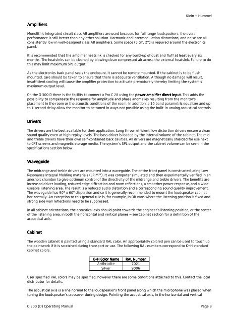
Cabinet<br />
The wooden cabinet is painted using a standard RAL color. An appropriately colored pen can be used to touch up<br />
the paintwork if it is scratched during transport or use. The following RAL numbers correspond to K+H standard<br />
cabinet colors.<br />
K+H Color Name<br />
RAL Number<br />
Anthracite 7021<br />
Silver 9006<br />
User specified RAL colors may be specified, however there are some conditions attached to this. Contact the local<br />
distributor for details.<br />
The acoustical axis is a line normal to the loudspeaker’s front panel along which the microphone was placed when<br />
tuning the loudspeaker’s crossover during design. Pointing the acoustical axis, in the horizontal and vertical<br />
O <strong>300</strong> (D) <strong>Operating</strong> <strong>Manual</strong> Page 9