O 300 (D) Operating Manual v01 - Klein + Hummel
O 300 (D) Operating Manual v01 - Klein + Hummel
O 300 (D) Operating Manual v01 - Klein + Hummel

You also want an ePaper? Increase the reach of your titles
YUMPU automatically turns print PDFs into web optimized ePapers that Google loves.
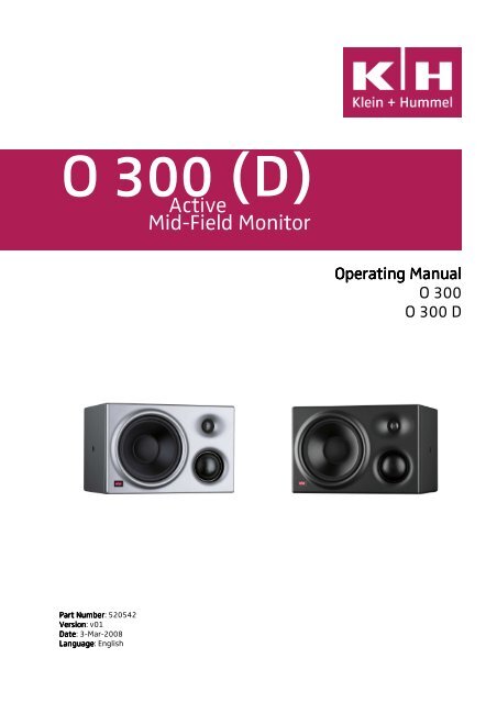
O <strong>300</strong> (D)<br />
Active<br />
Mid-Field Monitor<br />
<strong>Operating</strong> <strong>Manual</strong><br />
O <strong>300</strong><br />
O <strong>300</strong> D<br />
Part Number: 520542<br />
Version: <strong>v01</strong><br />
Date: 3-Mar-2008<br />
Language: English
<strong>Klein</strong> + <strong>Hummel</strong><br />
Introduction<br />
Thank-you for purchasing a <strong>Klein</strong> + <strong>Hummel</strong> loudspeaker. A Mathematically Modeled Dispersion waveguide<br />
(MMD), flexible acoustical controls, various input options and an extensive mounting hardware range allow the<br />
loudspeaker to be used in diverse acoustical conditions, with any source equipment and in a wide variety of<br />
physical locations. The latest acoustical and electrical techniques and components have been used to ensure the<br />
most accurate sound reproduction possible. <strong>Klein</strong> + <strong>Hummel</strong> products are designed for longevity so we hope you<br />
enjoy many happy years of using this product.<br />
Depending on the size, <strong>Klein</strong> + <strong>Hummel</strong>’s three-way systems are designed for use as near field monitors through<br />
to large main control room monitors. They can be used in music, broadcast, and post production studios for<br />
tracking, mixing, and mastering. They may be positioned free-standing or flush mounted into a wall, and can be<br />
mixed freely in multichannel systems.<br />
Before reading the rest of this operating manual, review the safety and warnings section towards the back of this<br />
book. Note that imperial dimensions are approximate.<br />
Package Contents<br />
The shipping carton contains:<br />
• This operating manual<br />
• A production calibration certificate<br />
• Product guarantee<br />
• The loudspeaker<br />
• A mains power cable (Euro or USA)<br />
• A trimmer and switch screwdriver<br />
Signal cables are not included. Options and accessories are listed at the end of this operating manual.<br />
Most Common Applications and Listening Distances<br />
The minimum, recommended, and maximum listening distances are shown below, together with their most<br />
common application:<br />
Distances<br />
Product<br />
Most t Common Application<br />
Minimum<br />
Recommended<br />
Maximum<br />
O <strong>300</strong> (D) Near-field monitoring 0.75 m (2.5’) 1.0 – 2.5 m (3’ - 8‘) 6 m (18’)<br />
In multichannel systems, one should ideally use the same product for all main channels. However, as the rear<br />
channels often contain less bass and the signals are mixed at a lower level than the front channels, the rear<br />
loudspeakers can be smaller - table below for details. The center loudspeaker should always be of the same type<br />
as the left and right loudspeaker. The subwoofer should be sufficient to keep up with the main loudspeakers - see<br />
subwoofer operating manual for details.<br />
Front<br />
Ideal Rears<br />
Smaller Rears<br />
Subwoofer(s)<br />
O 410 O 410 O <strong>300</strong> (D) Refer to subwoofer operating manuals<br />
O <strong>300</strong> (D) O <strong>300</strong> (D) O 110 (D), M52 (D) Refer to subwoofer operating manuals<br />
Please refer to the Product Selection Guide for more information about building systems using K+H products.<br />
O <strong>300</strong> (D) <strong>Operating</strong> <strong>Manual</strong> Page 1
<strong>Klein</strong> + <strong>Hummel</strong><br />
System Block Diagrams<br />
O <strong>300</strong> Block Diagram<br />
O <strong>300</strong> D Block Diagram<br />
Refer to the detailed product specifications section for information on the crossover frequencies, amplifier power,<br />
and driver types. When the Pro C 28 external controller is used on an O <strong>300</strong> D, all internal limiters are bypassed,<br />
except the bass channel peak limiter.<br />
O <strong>300</strong> (D) <strong>Operating</strong> <strong>Manual</strong> Page 2
<strong>Klein</strong> + <strong>Hummel</strong><br />
Electronics Panel Picture<br />
O <strong>300</strong> electronics panel<br />
O <strong>300</strong> D electronics panel<br />
O <strong>300</strong> (D) <strong>Operating</strong> <strong>Manual</strong> Page 3
<strong>Klein</strong> + <strong>Hummel</strong><br />
Analog Input Stage<br />
The O <strong>300</strong> input stage is a 14 kΩ electronically balanced type on a female XLR socket.<br />
The O <strong>300</strong> D input stage is a 14 kΩ transformer balanced type on a female XLR socket.<br />
Pin<br />
Signal<br />
1 Audio Ground<br />
2 Positive<br />
3 Negative<br />
Analog connections on the O <strong>300</strong> and O <strong>300</strong> D<br />
If there is a humming or buzzing sound coming from the loudspeaker, first check it is not the loudspeaker by<br />
disconnection the input signal cables. If the noise goes away it is not the loudspeaker itself and so the noises<br />
must be coming from the cabling or the source. There are various ways to increase the loudspeaker’s immunity<br />
from these external noises:<br />
• Use the ground lift switch to disconnect the audio ground from the electronics’ chassis ground. For safety<br />
reasons, the electronics chassis ground is always connected to the mains power earth pin.<br />
• Use an O <strong>300</strong> D which is fitted with a transformer balanced input stage. This is especially effective when<br />
combined with the ground lift switch.<br />
• If unbalanced cables are used, they can be specially wired – see picture below. Disconnect the cable screen<br />
from the RCA sleeve if there are still humming or buzzing sounds, and/or use the ground lift switch on the<br />
loudspeaker.<br />
Cable for connecting unbalanced sources to a balanced XLR input<br />
Digital Input Stage (O <strong>300</strong> D only)<br />
In the O <strong>300</strong>D there is a 16…24-bit, 32…96 kHz digital input stage that can accept AES3-2003 (commonly known<br />
as AES/EBU), AES3id-2001, and S/P-DIF (with a suitable connector converter) signals. De-emphasis is supported<br />
on 32, 44.1, 48, and 96 kHz sample rates. XLR and BNC connectors ensure good interconnectivity options.<br />
Uncompressed PCM AES3, AES3id, and S/P-DIF digital signals generally contain two audio channels (called<br />
“subframe A” and “subframe B”) on one cable (single-wire mode). A clock input is not required because<br />
loudspeakers are not audio sources and the clock signal is locally regenerated from data contained in the bit<br />
stream. The four-way signal selector switch on the rear panel allows selection of:<br />
O <strong>300</strong> (D) <strong>Operating</strong> <strong>Manual</strong> Page 4
<strong>Klein</strong> + <strong>Hummel</strong><br />
• “ANALOG” (XLR input connector only).<br />
• “R” (digital subframe B)<br />
• “L” (digital subframe A)<br />
• “MONO” (mono sum of subframe A and subframe B with a 4.5 dB attenuation)<br />
There is no digital output from the BNC connector when the XLR input is presented with an analog signal,<br />
therefore the O <strong>300</strong>D cannot be used as an analogue-to-digital converter.<br />
Always use good quality cables with the correct impedance and appropriate termination to achieve these<br />
maximum cable lengths:<br />
Format<br />
Impedance<br />
Cable Length<br />
(Connector)<br />
S/P-DIF (RCA) 75 Ω up to 10 m (30’)<br />
AES3 (XLR) 110 Ω up to 100 m (<strong>300</strong>’)<br />
AES3id (BNC) 75 Ω up to 1000 m (<strong>300</strong>0’)<br />
An AES3 signal (applied to the XLR connector) is point-to-point and may not be looped, so the BNC connector is<br />
used to connect additional monitors to the AES3 signal. The signal selector switch on the first loudspeaker should<br />
be set to the “L”, “R”, or “MONO” setting. This outputs an AES3id signal from the BNC connector for connecting<br />
additional monitors to the original AES3 signal. The BNC connector is not internally terminated so a single 75 Ω<br />
termination is required at the end of the BNC transmission line. This can be realized using T-piece and a 75 Ω<br />
terminator (not supplied).<br />
XLR digital input connections on the O <strong>300</strong> D<br />
An AES3id or S/P-DIF signal (applied to the BNC connector) can be looped using a T-piece connector (not<br />
supplied) for connecting additional monitors to the input signal. The signal selector switch on the first<br />
loudspeaker should be set to “L”, “R”, or “MONO” setting. An appropriate setting should be made on the rear<br />
panel signal selector switch depending on the signal channel order and loudspeaker position. See picture below:<br />
O <strong>300</strong> (D) <strong>Operating</strong> <strong>Manual</strong> Page 5
<strong>Klein</strong> + <strong>Hummel</strong><br />
BNC digital input connections on the O <strong>300</strong> D<br />
To connect multiple O <strong>300</strong> D monitors together, use BNC T-piece connectors (not supplied) - see picture below. in<br />
The digital input can be applied to either the XLR or BNC input of the first loudspeaker in the chain. BNC<br />
connectors should be used for the rest of the loudspeakers in the chain. An appropriate setting should be made<br />
on the rear panel signal selector switch depending on the location of the loudspeaker.<br />
Multiple O <strong>300</strong> D connections using BNC<br />
Note that the BNC connector has no output driver. When using the AES3 input, the output level is derived<br />
passively from the AES3 signal’s input level. This has a wide tolerance, therefore the length of the<br />
interconnection cable and number of loudspeakers will depend on the level of the source signal and quality of the<br />
interconnecting cables.<br />
It is not possible to have an analog XLR and a digital BNC cable simultaneously connected to the loudspeaker as<br />
the BNC connector is parallel connected to the XLR input.<br />
Acoustic<br />
coustical<br />
Response<br />
When the O <strong>300</strong> D was developed it was tuned to have a response close to the O 198 it replaced. This had a flat<br />
response when located in its typical usage position, i.e. on a meter bridge. This is not flat when measured in<br />
anechoic conditions. The O <strong>300</strong> D has a good sound straight out of the box for the typical use of the product –<br />
near field monitoring. For other acoustical conditions, for example free standing in a large room, some<br />
adjustment of the acoustical control is recommended. For a flat pass band magnitude response in anechoic<br />
conditions, set the acoustical controls to bass 0 dB, mid -2 dB, and treble -1 dB.<br />
When the O <strong>300</strong> was designed, it was tuned to have a flat response in anechoic conditions when the switches are<br />
set to 0 dB. This works well when the monitor is free standing in a large room, but adjustments are required the<br />
loudspeaker is placed in other acoustical conditions, such as next to console.<br />
In either case, when a loudspeaker is installed into a listening environment the response changes and thus should<br />
be corrected back to a flat response. It is therefore expected that the controls will need adjustment to improve<br />
O <strong>300</strong> (D) <strong>Operating</strong> <strong>Manual</strong> Page 6
<strong>Klein</strong> + <strong>Hummel</strong><br />
the in-situ response of the loudspeaker. It is possible to achieve the same response from the O <strong>300</strong> and O <strong>300</strong> D<br />
when the switches are set to the same physical position on the backplate.<br />
Acoustical Controls<br />
The acoustical controls are low-order analog filters designed to compensate for some of the acoustical issues<br />
commonly found in listening environments. The acoustical controls’ settings will depend on the loudspeaker’s<br />
location and will probably be different for the same loudspeaker type installed in different locations in the same<br />
room. In a symmetrical installation, left/right pairs (front or back) will probably have the same acoustical<br />
settings. Suggested settings are shown after this description of the controls:<br />
The bass control is used to compensate for the effect of loading due to nearby large solid boundaries such as<br />
walls. Four settings are available: 0, -3, -6, and -9 dB.<br />
The mid<br />
control is used to compensate for the acoustical loading experienced when the loudspeaker cabinet is<br />
placed near a large reflecting surface, such as a mixing console. Four settings are available: +2, 0, -2, and -4 dB.<br />
The treble control affects the treble driver output level and can be used to compensate for insufficient or<br />
excessive high frequency damping in the room. The treble control is often set to suit the listener’s taste, although<br />
in well-controlled environments there should be little reason to adjust it away from 0 dB. Four settings are<br />
available: +2, +1, 0, and -1 dB.<br />
It is advised that an acoustical measurement system be used to set these controls in the most appropriate way<br />
for the loudspeaker’s location. This is especially true of the parametric equalizer’s controls. In the absence of<br />
appropriate equipment the following settings are recommended as a good starting point for further adjustment:<br />
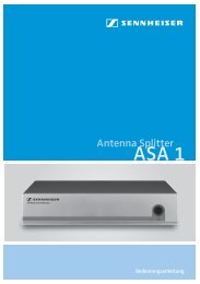
Acoustical Controls<br />
O <strong>300</strong><br />
O <strong>300</strong> D<br />
Loudspeaker Location<br />
Bass<br />
Mid<br />
Treble<br />
Mid<br />
Treble<br />
In a corner -9 dB -2 dB - -4 dB -<br />
Next to or flush mounted in a solid wall -6 dB - - -2 dB -<br />
Next to or flush mounted in a soft wall -3 dB - - - -<br />
Free standing in an untreated room -3 dB -2 dB -1 dB -4 dB -2 dB<br />
Free standing in a well-treated room - - - -2 dB -1 dB<br />
Near a desktop or an a meter bridge 1 - -2 dB - - -<br />
1. Setting should be used in addition to the one of the top five settings.<br />
O <strong>300</strong> D Acoustical Controls O <strong>300</strong> Acoustical Controls<br />
Note: the parametric equalizer’s response is not shown on the above graphs as it is freely adjustable within the<br />
stated parameter ranges.<br />
The input attenuator control allows the loudspeaker to be matched to a wide range of equipment outputs whilst<br />
maintaining the desired acoustical output. In the O <strong>300</strong> D, the attenuator affects the output level as it is<br />
positioned after the DAC. As with any other component in the audio chain, it is best to use the lowest gain for the<br />
application so as to minimize amplification of the preceding equipment’s source noise. To check this, if the noise<br />
drops dramatically when the input cable is unplugged, the noise is coming from the source not the loudspeaker.<br />
The default setting is “0 dB”, and this gives an output level of 96 dB SPL at 1 m when the input signal is 0 dBu<br />
O <strong>300</strong> (D) <strong>Operating</strong> <strong>Manual</strong> Page 7
<strong>Klein</strong> + <strong>Hummel</strong><br />
(0.775 V), which is the same as 100 dB SPL at 1 m when the input signal is +4 dBu (1.23 V). Below are some<br />
examples of how to calculate the output level:<br />
Input signal [dBu] 0 (0.775 V) 0 (0.775 V) +4 (1.23 V) -20 (77.5 mV)<br />
Input attenuator setting [dB] 0 -24 0 0<br />
Loudspeaker output for 0 dBu input [dB SPL] 96 96 96 96<br />
Sound output of loudspeaker [dB SPL at 1m] 96 72 100 76<br />
In Europe 0 dBu is -18 dBFS (EBU standard R68). In the US +4 dBu is -20 dBFS (SMPTE standard RP155). These<br />
dBu values should equate to 85 dB SPL at the listening position. It is typical in the broadcast industry to use a<br />
reference level of 79 dB SPL at the listening position. Near field loudspeakers can be as close as 1 m from the<br />
listening position, whereas loudspeakers in a Dolby certified movie mixing room should be at least 5 m from the<br />
listening position. In the examples below, it is assumed that the listener is inside the room radius and thus the<br />
sound field decays according to 20 log 10 (r), however this may not always be the case.<br />
Input signal [dBu] 0 (0.775 V) +4 (1.23 V)<br />
Loudspeaker output for 0 dBu input [dB SPL] 96 96<br />
Input attenuator [dB] -5 -9<br />
Listening distance [m] (dB change) 2 m (-6 dB) 2 m (-6 dB)<br />
Loudspeaker output level [dB SPL] 85 85<br />
The maximum level that the O <strong>300</strong> electronic balanced input stage can accept is +20 dBu (7.75 V). The maximum<br />
level that the O <strong>300</strong> D transformer balanced input stage can accept is +24 dBu (12.3 V). To avoid clipping the<br />
input stage, decrease the amount of input attenuation. The maximum acoustical output of the loudspeaker is<br />
limited by the protection system. In general, larger loudspeakers can play louder and for longer periods than<br />
smaller loudspeakers.<br />
Other Controls<br />
The power<br />
On/Off switch turns the mains power completely on and off. The applied mains power voltage should<br />
be within -15% and +10% of the value shown on the electronics panel. The mains fuse value depends on the<br />
mains voltage and should be:<br />
Mains Voltage<br />
Fuse (250 V)<br />
220 - 240 V T 1.6<br />
120 V T 3.15<br />
100 V T 4<br />
Crossover<br />
Using 4 th order filters, the crossover divides the input signal into three bands for reproduction by the appropriate<br />
sized driver. Time alignment of drivers is accomplished with the physical position of the drivers on the front<br />
panel, therefore electronic alignment is necessary. In addition to this an extensive protection system ensures that<br />
the loudspeaker is not damaged if a large signal is applied to the input. The front panel K+H logo flashes when<br />
the protection system is active. If this happens, reduce the input signal. If this happens regularly, use a larger<br />
loudspeaker with a higher SPL output, or add a subwoofer to handle the high-level low-frequency energy. The<br />
protection system consists of: thermal and peak limiters for the amplifiers, thermal modeling of the drivers, and<br />
an excursion limiter for the drivers.<br />
The protection system is not a compressor, it is designed to protect the loudspeaker from damage, and the<br />
flashing K+H logo tells the user it is active. The protection cannot protect against sustained abuse of the<br />
loudspeaker, i.e. consistently playing the loudspeaker for long periods of time with the protect light on, so avoid<br />
this to ensure a long life from this product.<br />
There are also production trimmers in the crossover section which are hidden from view to avoid “accidental”<br />
adjustment. These should only be adjusted by qualified personnel with specialized measurement equipment. If a<br />
component critical for sound quality, e.g. bass driver, is changed, the loudspeaker should ideally be recalibrated in<br />
a <strong>Klein</strong> + <strong>Hummel</strong> Continental Service Center, i.e. one equipped with an anechoic chamber.<br />
O <strong>300</strong> (D) <strong>Operating</strong> <strong>Manual</strong> Page 8
<strong>Klein</strong> + <strong>Hummel</strong><br />
Amplifiers<br />
Monolithic integrated circuit class AB amplifiers are used because, for full range loudspeakers, the overall<br />
performance is still better than any other solution. Harmonic and intermodulation distortions, and noise are all<br />
consistently low in well-designed class AB amplifiers. Some space (5 cm, 2”) is required around the electronics<br />
panel.<br />
It is recommended that the amplifier heatsink is checked for any build-up of dust and fluff at least every six<br />
months. The heatsinks can be cleaned by blowing clean compressed air across the external heatsink. Failure to do<br />
this may limit maximum SPL output.<br />
As the electronics back panel seals the enclosure, it cannot be remote mounted. If the cabinet is to be flush<br />
mounted, care should be taken to ensure that there is adequate ventilation. Although no damage will result,<br />
insufficient cooling will cause the amplifier protection to activate prematurely thereby limiting the system’s<br />
maximum output level.<br />
On the O <strong>300</strong> D there is the facility to connect a Pro C 28 using the power amplifier direct input. This adds the<br />
possibility to compensate the response for amplitude and phase anomalies resulting from the monitor’s<br />
placement in the room or the acoustic conditions of the room. In addition, a 10 band parametric equalizer and up<br />
to 1 second delay allow the monitor to be tuned in ways not possible using the built-in analog acoustical controls.<br />
Drivers<br />
The drivers are the best available for their application. Long throw, efficient, low distortion drivers ensure a clean<br />
sound quality even at high replay levels. The bass driver is loaded by the internal volume of the cabinet. The mid<br />
and treble drivers have their own self-contained back cavities. All drivers are magnetically shielded for use next<br />
to CRT screens and magnetic storage media. The system’s SPL output and the cabinet volume can be seen in the<br />
specifications section below.<br />
Waveguide<br />
The midrange and treble drivers are mounted into a waveguide. The entire front panel is constructed using Low<br />
Resonance Integral Molding materials (LRIM). It was computer simulated and then experimentally verified in an<br />
anechoic chamber to give optimum control of the directivity of the midrange and treble drivers. The benefits are<br />
increased driver loading, reduced edge diffraction and room reflections, a smoother power response, and a wide<br />
useable listening area. The result is a reduced audio distortion and a corresponding sound quality improvement.<br />
The waveguide has 90° x 60° dispersion and so it is generally recommended to mount the loudspeaker cabinet<br />
horizontally. An exception to this general rule is, for example, in OB vans where the listening position is fixed and<br />
strong side wall reflections need to be suppressed.<br />
In all cabinet orientations, the acoustical axis should point towards the engineer’s listening position, or the center<br />
of the listening area, in both the horizontal and vertical planes – see Cabinet section for a definition of the<br />
acoustical axis.<br />
Cabinet<br />
The wooden cabinet is painted using a standard RAL color. An appropriately colored pen can be used to touch up<br />
the paintwork if it is scratched during transport or use. The following RAL numbers correspond to K+H standard<br />
cabinet colors.<br />
K+H Color Name<br />
RAL Number<br />
Anthracite 7021<br />
Silver 9006<br />
User specified RAL colors may be specified, however there are some conditions attached to this. Contact the local<br />
distributor for details.<br />
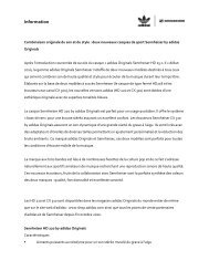
The acoustical axis is a line normal to the loudspeaker’s front panel along which the microphone was placed when<br />
tuning the loudspeaker’s crossover during design. Pointing the acoustical axis, in the horizontal and vertical<br />
O <strong>300</strong> (D) <strong>Operating</strong> <strong>Manual</strong> Page 9
<strong>Klein</strong> + <strong>Hummel</strong><br />
planes, towards the listening position or centre of the listening area will give the best measured and perceived<br />
sound quality. For three-way loudspeakers in the <strong>Klein</strong> + <strong>Hummel</strong> range, the acoustical axis is located on the midpoint<br />
of the midrange and tweeter drivers.<br />
Product<br />
x dimension<br />
y dimension<br />
O <strong>300</strong> 30.5 cm (12“) 14.5 cm (5 3 / 4 “)<br />
O <strong>300</strong> D 30.5 cm (12“) 14.5 cm (5 3 / 4 “)<br />
y<br />
O <strong>300</strong> (D) Acoustical Axis<br />
An M8 thread is positioned on either side of the cabinet for attaching an LH 25 “U” bracket. The plastic plugs<br />
should be refitted if the LH 25 is later removed.<br />
Angled metal brackets on the rear panel can be used to mount the cabinet on a wall or as handles to lift the<br />
loudspeaker. Note: Do not place the O <strong>300</strong> (D) face down on a flat surface as the midrange driver will be<br />
damaged.<br />
x<br />
System Use<br />
<strong>Klein</strong> + <strong>Hummel</strong> loudspeakers should only be used indoors and in these ambient conditions:<br />
• +10° C to +40° C (+50° F to +104° F),
Loudspeaker Name<br />
ITU-R BS.775-1 Angle ANSI/SMPTE 202M Angle<br />
Left -30° -22.5°<br />
Center 0° 0°<br />
Right 30° 22.5°<br />
Left Surround -110°±10° An array to the left<br />
Right Surround 110°±10° An array to the right<br />
<strong>Klein</strong> + <strong>Hummel</strong><br />
The O <strong>300</strong> (D) comes in two forms: named “left” and “right”. In a two-channel system, one of each type is used<br />
and the bass drivers, normally, positioned on the inside. In a multichannel system, “left”/”right” pairs can be<br />
used for rears and sides. For the center, either a “left” or “right” may be used, with the acoustical axis lined up<br />
along the centre line of the loudspeaker array – see picture below. Ideally, all front loudspeakers are positioned at<br />
the same height.<br />
↑ ↑ ↑<br />
-30 deg 0 deg +30 deg<br />
Using the O <strong>300</strong> (D) as a center loudspeaker<br />
The loudspeaker should be placed on a circle to ensure equal time of arrival of the audio from all loudspeakers.<br />
Failing this, appropriate electronic time delays should be added to compensate for time of flight differences. This<br />
can either be a Pro C 28 inserted into the signal chain before an O <strong>300</strong> or a Pro C 28 attached to the power<br />
amplifier direct input on an O <strong>300</strong> D.<br />
If the loudspeaker is used free standing, good quality loudspeaker stands and suitable accessories (see<br />
Accessories and Options section) are recommended.<br />
The benefits of flush mounting are reduced cabinet edge diffraction (smoother midrange), increased bass driver<br />
loading (reduced bass distortion), and elimination of rear wall cancellations (smoother bass response). It is a<br />
good idea to employ an experienced acoustic engineer to design an effective flush mounting wall. Recommended<br />
acoustical control settings are shown in the Acoustical Controls section. If the loudspeaker must be covered, use a<br />
thin open weave cloth. Two layers of very thin material will improve opacity.<br />
Before trimming the levels, calibrate each loudspeaker’s response:<br />
• In studio applications, the response of each loudspeaker at the listening position should be flat.<br />
• In movie applications, the response of each loudspeaker should be one of the X-curve shapes, depending on<br />
the size of the room (see ANSI/SMPTE 202M).<br />
• In home applications, the response of each loudspeaker should be set for subjective audio quality. This is not<br />
necessarily a flat response, but generally, with time, a gently downward sloping response with increasing<br />
frequency is often preferred.<br />
Absolute acoustic level calibration is achieved using a sound level meter set to ‘C’-weighting and a “slow”<br />
integration time. Play a broadband pink noise test signal set to -18 dBFS (Europe) or -20 dBFS (USA) on the<br />
console meters and measure the sound pressure level at the listening position. Then adjust each channel’s level<br />
(can also be adjusted on all loudspeakers for a specific channel) until the desired level is achieved:<br />
Application<br />
Movie<br />
Broadcast<br />
Music<br />
SPL<br />
85 dB(C)<br />
79 dB(C)<br />
Engineer’s preference<br />
For information on setting up a subwoofer with these main loudspeakers, please refer to the operating manual<br />
supplied with the subwoofer.<br />
O <strong>300</strong> (D) <strong>Operating</strong> <strong>Manual</strong> Page 11
<strong>Klein</strong> + <strong>Hummel</strong><br />
Technical Specifications<br />
O <strong>300</strong><br />
O <strong>300</strong> D<br />
Acoustics<br />
-3 dB free field frequency response 35 Hz … 24 kHz, ± 3 dB 35 Hz … 24 kHz, ± 3 dB<br />
Pass band free field frequency response 40 Hz … 20 kHz, ± 2 dB 40 Hz … 20 kHz, ± 2 dB<br />
Self-generated noise 100 Hz)<br />
Max. SPL In half space at 3% THD 112.8 dB SPL 112.8 dB SPL<br />
Averaged between 100 Hz and 6 kHz 100 Hz and 6 kHz<br />
Electronics<br />
Woofer amplifier, cont.(peak) output power* 150 W (250 W) 150 W (250 W)<br />
Mid amplifier, cont. (peak) output power* 65 W (75 W) 65 W (75 W)<br />
Tweeter amplifier, cont.(peak) output power* 65 W (110 W) 65 W (110 W)<br />
Controller design analog, active Internal active analog, or<br />
external DSP (K+H Pro C 28)<br />
Crossover Frequency 650 Hz/3.3 kHz 650 Hz/3.3 kHz<br />
Crossover Slope (dB/oct.) 24 24<br />
Equalization: Low cut – –<br />
Bass 0, -3, -6, -9 dB 0, -3, -6, -9 dB<br />
Mid +2, 0, -2, -4 dB +2, 0, -2, -4 dB<br />
High +1, +2, 0, -1 dB +1, +2, 0, -1 dB<br />
Time of Flight adjustment delay – 8 … 1000 ms using a Pro C 28<br />
Protection circuitry Limiter: low, mid, high Limiter: low, mid, high<br />
Infrasonic filter frequency; slope 30 Hz; 6 dB/oct. 30 Hz; 6 dB/oct.<br />
Analog Input<br />
Impedance, electrically balanced XLR, 14 kΩ -<br />
Impedance, transformer balanced - XLR, 14 kΩ<br />
Input sensitivity +6 dBu +6 dBu<br />
Attenuator 0 … -24 dB 0 … -24 dB<br />
CMRR >60 dB @ 15 kHz >60 dB @ 15 kHz<br />
Digital Input/Output<br />
Format XLR (Format BNC) - AES3 (AES3id, S/P-DIF)<br />
Impedance XLR, balanced - 110 Ω<br />
Impedance BNC, unbalanced - 75 Ω (input/output)<br />
Input switching - Analog / Digital L, R, Mono<br />
Digital converter: resolution, design - 16 … 24-bit DAC, ∆Σ<br />
sampling rate - 32 … 96 kHz<br />
Digital sensitivity - -12.5 dBFS<br />
D-A dynamic range - 120 dB<br />
Displays and Mains Power<br />
Displays and indicators: power on K + H logo “Red” K + H logo “Red”<br />
limit/clip K + H logo “Flashing” K + H logo “Flashing”<br />
Mains power 230, 120, or 100 V AC 230, 120, or 100 V AC<br />
Power consumption - Idle 18 VA 19 VA<br />
Power consumption - Full output AC 240 VA 241 VA<br />
Mechanics<br />
Height x width x depth, mm 253 x 383 x 290 mm 253 x 383 x 290 mm<br />
inches 10” x 15 1 / 8 ” x 11 3 / 8 ” 10” x 15 1 / 8 ” x 11 3 / 8 ”<br />
Internal net volume 18.3 liters 18.3 liters<br />
External volume 28 liters 28 liters<br />
Weight 13.4 kg (29.5 lbs) 13.4 kg (29.5lbs)<br />
Drivers Magnetically shielded Magnetically shielded<br />
Woofer 210 mm (8") 210 mm (8")<br />
Midrange 76 mm (3") 76 mm (3")<br />
Tweeter 25 mm (1") 25 mm (1")<br />
Mounting points 2 x M8 on sides 2 x M8 on sides<br />
Mounting hardware included Rear panel bracket Rear panel bracket<br />
Cabinet surface finish Painted Painted<br />
Color: standard<br />
Anthracite (RAL 7021) or<br />
silver (RAL 9006)<br />
Anthracite (RAL 7021) or<br />
silver (RAL 9006)<br />
Color: custom User specified RAL User specified RAL<br />
Baffle cover Optional metal grille Optional metal grille<br />
*THD+N < 0.1 % with limiter deactivated<br />
O <strong>300</strong> (D) <strong>Operating</strong> <strong>Manual</strong> Page 12
<strong>Klein</strong> + <strong>Hummel</strong><br />
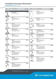
Acoustical Measurements<br />
Below are acoustical measurements conducted in anechoic conditions at 1 m. Color versions of these graphs can<br />
be found on the appropriate product page of the klein-hummel.com web site.<br />
O <strong>300</strong> (D) free-field field response O <strong>300</strong> (D) group delay<br />
O <strong>300</strong> (D) horizontal directivity plot O <strong>300</strong> (D) vertical directivity plot<br />
O <strong>300</strong> (D) distortion at 95 dB SPL O <strong>300</strong> (D) Maximum SPL at 1 m<br />
O <strong>300</strong> (D) <strong>Operating</strong> <strong>Manual</strong> Page 13
<strong>Klein</strong> + <strong>Hummel</strong><br />
O <strong>300</strong> (D) cumulative spectral decay<br />
Accessories and Options<br />
In this section is a description of the options and accessories that are available for the products covered in the<br />
operating manual. Note that options and accessories are fitted at the user’s own risk and that safety and<br />
warning instructions should be observed.<br />
Mounting hardware<br />
A collection of hardware for mounting the loudspeaker:<br />
LH 25 (W)<br />
LH 28 (W)<br />
LH 29<br />
LH 37<br />
“U” bracket – used to fit the loudspeaker onto a ceiling, wall, or other adapters. Also gives vertical<br />
adjustment of the cabinet. Available in white and black.<br />
Tripod stand adapter – used to fit the loudspeaker onto a standard 35 mm (1.4”) tube tripod stand<br />
(external fit with screw thread). Available in white and black.<br />
TV spigot adapter – used to fit the loudspeaker onto a standard TV spigot used in broadcast studios<br />
(internal fit).<br />
Tripod flange adapter – used to fit the loudspeaker into a standard 35 mm (1.4”) flange fitting.<br />
LH 25 (W) – “U” bracket LH 28 (W) – Tripod stand adapter<br />
LH 29 – TV spigot adapter LH 37 – Tripod flange adapter<br />
O <strong>300</strong> (D) <strong>Operating</strong> <strong>Manual</strong> Page 14
<strong>Klein</strong> + <strong>Hummel</strong><br />
Suitable combinations of the above hardware are:<br />
Location of Loudspeaker<br />
Hardware Combinations<br />
On a Floor Stand<br />
(tripod, TV spigot, or with a<br />
5/8" thread)<br />
LH 25<br />
LH 25 + LH 28<br />
LH 25 + LH 29<br />
On a Subwoofer<br />
LH 25 + LH 37<br />
(fitted with a flange)<br />
On a meter bridge<br />
No hardware required<br />
On a Wall LH 25<br />
Included rear panel brackets<br />
Off a Ceiling LH 25<br />
Off a Lighting or Truss Bar LH 25 + LH 29<br />
Mechanical drawings of these accessories can be found on line at www.klein-hummel.com.<br />
Controller multicore cable (CMK 5)<br />
A cable used to connect a Pro C 28 to the O <strong>300</strong> D (pictured below).<br />
Metal grille<br />
(GO <strong>300</strong>)<br />
A metal grille can be attached to the front of the loudspeaker to protect the drivers. It simply clips into the<br />
grooves on the long sides of the cabinet and adds 22 mm (7/8”) to the depth and 3 mm (1/8”) to the height of<br />
the cabinet. It is damped to avoid rattles and has been designed for acoustic transparency (black version pictured<br />
below). The grille is available in black and silver.<br />
Flight case (FO <strong>300</strong>)<br />
As the original packing is primarily designed to get the loudspeaker from the factory to the end user, it is highly<br />
recommended that a flight case is used if the loudspeaker is regularly moved between locations. One O <strong>300</strong> (D)<br />
can be packed in the flight case.<br />
CMK 5 – Multicore cable GO <strong>300</strong> – Metal Grille<br />
O <strong>300</strong> (D) <strong>Operating</strong> <strong>Manual</strong> Page 15
<strong>Klein</strong> + <strong>Hummel</strong><br />
Safety and Warnings<br />
In addition to specific warnings throughout this document, please observe these additional general instructions.<br />
The term “loudspeaker” includes the case when the electronics of an active loudspeaker is installed into a Remote<br />
Electronics Kit, or when it is still located in the back of the cabinet.<br />
This symbol means that a high voltage is to found nearby. Take appropriate precautions to avoid<br />
electric shocks.<br />
This symbol means that hot parts of the product may be found nearby. Take appropriate<br />
precautions to avoid burns.<br />
General<br />
• Keep these instructions in a safe place for future reference.<br />
• Failure to follow the safety and warning instructions contained in this document voids the warranty.<br />
• This product should be used for the intention for which it was designed and as described in this document.<br />
Environment<br />
• Ensure that the room in which you use this product is wired in accordance with the local electrical code and<br />
checked by a qualified inspector.<br />
• A correctly earthed mains power connection should always be used.<br />
• If access to the interior electronics is required, disconnect it from the mains power and allow electrical energy<br />
storage devices, such as capacitors and transformers, to discharge.<br />
• Other electronic products may generate sufficient heat to require ventilation.<br />
• Do not block or cover heatsinks, fans, or vents.<br />
• Unless otherwise stated, this product is designed to be used indoors only.<br />
• Do not expose this product to water, any other liquids, moisture, or naked flames.<br />
• Do not install this product into hot, humid, or excessively dusty locations, or into direct sunlight.<br />
• Avoid installing this product into locations where it will experience externally generated vibrations or heat<br />
(e.g. radiators).<br />
• If the product is moved from a cold environment into a warm one (such as from a vehicle into a building), it is<br />
possible that condensation will form. Please allow the product sufficient time for acclimatization to room<br />
temperature before using.<br />
• Wherever an amplifier is located, a free flow of air should be maintained by leaving a gap of at least 5 cm<br />
(2”) around it. A flush mounted cabinet with the electronics panel still installed should be well-ventilated to<br />
avoid heat build-up and possible risk of fire.<br />
Use<br />
• The equipment should be mounted by a suitably qualified professional in accordance with local, national, and<br />
international regulations and standards.<br />
• Falling equipment can damage itself, people, and other objects, so do not place this unit on any unstable<br />
platform, cart, trolley, stand, table, or mounting hardware.<br />
• Do not use accessories and options with this product that are not approved by <strong>Klein</strong> + <strong>Hummel</strong>.<br />
• Mounting hardware must be attached to the appropriate hardware and attachment points rated and<br />
intended for such use.<br />
• Ensure that the operating voltage of this product matches that of the local mains voltage.<br />
• Use the power cable that came with this product as this has been manufactured to international safety<br />
standards. If it has been damaged obtain a similarly certified and specified mains power cable.<br />
• This product should be unplugged from the mains power and the signal sources if is not to be used for an<br />
extended period of time, or during lightening storms.<br />
• The power switch on this product should be set to off before applying mains power via the mains power<br />
cable.<br />
• Some parts of this product, particularly power amplifier components, can become hot to the touch. Do not<br />
touch these parts until they have cooled down.<br />
• Never touch the loudspeaker’s drivers.<br />
• Loudspeakers are often capable of producing a sound pressure level in excess of 85 dB. This may cause<br />
permanent hearing damage so user caution is recommended. Noise exposure is a function of SPL and time, so<br />
observe local regulations when listening at high levels for a long time. Hearing protection may be required.<br />
O <strong>300</strong> (D) <strong>Operating</strong> <strong>Manual</strong> Page 16
<strong>Klein</strong> + <strong>Hummel</strong><br />
Servicing<br />
• Repairs, maintenance, or other servicing of this product when its interior compartment is exposed should<br />
only be performed by <strong>Klein</strong> + <strong>Hummel</strong> authorized service engineers familiar with the equipment and risks<br />
involved in handling electronics.<br />
• Servicing may be required in the event of exposure to unfavorable environmental conditions, such as liquids,<br />
excessive heat, or a lightning strike.<br />
• Amplifier outputs may carry high voltages so take appropriate precautions, for example, connect the cables<br />
before powering up.<br />
• When replacing a fuse, ensure that a brand new fuse is used. It must be exactly the same type, value, and<br />
voltage as the original, as stated in the product’s technical specifications or on the circuit board.<br />
Maintenance and Servicing<br />
• There are no user serviceable parts inside the standard version of this product. Repairs should only be<br />
undertaken by <strong>Klein</strong> + <strong>Hummel</strong> certified service engineer.<br />
• Options and accessories are fitted at the user’s own risk.<br />
• Products may be cleaned using a non-abrasive cloth lightly damped with water. Disconnect the mains power<br />
cable when cleaning to avoid risk of electric shock. Do not use alcohol-based cleaners.<br />
• The electronics should only be opened by non-“<strong>Klein</strong> + <strong>Hummel</strong> certified service engineer” for the installation<br />
of user installable options as described in the product’s operating manual. The mains power cable should be<br />
disconnected whenever the electronics panel is opened.<br />
• If the main fuse blows, the product should be checked by a <strong>Klein</strong> + <strong>Hummel</strong> certified service engineer.<br />
Guarantee<br />
This product comes with a guarantee, a copy of which is enclosed with this product.<br />
Recycling<br />
Attention to product quality in the design phase ensures, firstly, that products have a long life and that, secondly,<br />
all parts of a product may be reused or recycled at the end of that life. An extensive product servicing network<br />
ensures that products can be repaired in the event of the premature failure of a part, or as a way to prolong the<br />
life of a product that would otherwise be considered a candidate for landfill. Eventually there comes a time when<br />
a product is considered beyond repair (for economic reasons or lack of parts), so the parts must be disposed of in<br />
a suitable manner. The disposal should conform to local environmental regulations and be conducted in an<br />
authorized recycling facility.<br />
Loudspeakers and electronic products consist of some or all of these components:<br />
Item<br />
Material<br />
Recycling Instructions<br />
Loudspeaker Cabinets Wood (MDF), steel, aluminum,<br />
Separate materials then recycle<br />
polyurethane or a combination<br />
Drivers Aluminum, copper, paper and plastics Separate materials then recycle<br />
Damping Materials Sheep or polyester wool Compost<br />
Electronics Panel Aluminum Remove electronics and recycle<br />
Electronics Various Recycle in an approved recycling facility<br />
Remote Electronics Kits Steel and some electronics Separate materials then recycle<br />
Cables and Connectors Metals and/or plastic Reuse or recycle<br />
Packing Material Cardboard, wood and/or plastics Separate materials then recycle<br />
User <strong>Manual</strong>s and Sales<br />
Literature<br />
Paper and cardboard<br />
Recycle<br />
O <strong>300</strong> (D) <strong>Operating</strong> <strong>Manual</strong> Page 17
<strong>Klein</strong> + <strong>Hummel</strong><br />
EC Declaration of Conformity<br />
This equipment is in compliance with the essential requirements and other relevant provisions of Directives<br />
89/336/EC and 73/23/EC. The declaration is available on the internet site at www.klein-hummel.com. Before<br />
putting the device into operation, please observe any respective country-specific regulations.<br />
For loudspeakers fitted with digital inputs: Compliance to FCC Rules<br />
This device complies with part 15 of the FCC Rules and with RSS-210 of Industry Canada. Operation is subject to<br />
the following two conditions:<br />
• This device may not cause harmful interference, and<br />
• This device must accept any interference received, including interference that may cause undesired operation.<br />
This equipment has been tested and found to comply with the limits for a Class B digital device, pursuant to part<br />
15 of the FCC Rules. These limits are designed to provide reasonable protection against harmful interference in a<br />
residential installation. This equipment generates, uses and can radiate radio frequency energy and, if not<br />
installed and used in accordance with the instructions, may cause harmful interference to radio communications.<br />
However, there is no guarantee that interference will not occur in a particular installation. If this equipment does<br />
cause harmful interference to radio or television reception, which can be determined by turning the equipment<br />
off and on, the user is encouraged to try to correct the interference by one or more of the following measures:<br />
• Reorient or relocate the receiving antenna.<br />
• Increase the separation between the equipment and receiver.<br />
• Connect the equipment into an outlet on a circuit different from that to which the receiver is connected.<br />
• Consult the dealer or an experienced radio/TV technician for help.<br />
This class B digital apparatus complies with the Canadian ICES-003<br />
Changes or modifications to this equipment not expressly approved by <strong>Klein</strong> + <strong>Hummel</strong> may void the FCC<br />
authorization to operate this equipment.<br />
O <strong>300</strong> (D) <strong>Operating</strong> <strong>Manual</strong> Page 18
The following are trademarks of K+H Vertriebs- und Entwicklungsgesellschaft mbH.<br />
• “Low Resonance Integral Molding” and “LRIM”<br />
• “Mathematically Modeled Dispersion” and “MMD”<br />
Other company, product, or service names may be trademarks or service marks of other organizations.<br />
<strong>Klein</strong> + <strong>Hummel</strong> reserve the right to change product specifications without notice. Exceptions and omissions<br />
excluded.<br />
K+H Vertriebs- und Entwicklungsgesellschaft mbH<br />
Auf dem Kessellande 4a, 30900 Wedemark, Germany.<br />
Phone: +49 (5130) 58 48 0<br />
Fax: +49 (5130) 58 48 11<br />
E-mail: enquiries@klein-hummel.com<br />
Web site: www.klein-hummel.com