User's Manual - Kling & Freitag
User's Manual - Kling & Freitag
User's Manual - Kling & Freitag

You also want an ePaper? Increase the reach of your titles
YUMPU automatically turns print PDFs into web optimized ePapers that Google loves.
K&F CA 205<br />
Die Version CA 106 F weicht in Form und Aussehen von<br />
dieser Abbildung ab.<br />
User‘s Benutzerhandbuch<br />
<strong>Manual</strong><br />
Version Version 1.0 3.1.<br />
Released: Stand: 08.06.2006 08.11.2006<br />
Important Information,<br />
Please Read Before Use!<br />
KLING & FREITAG GmbH<br />
Junkersstrasse 14<br />
D-30179 Hannover<br />
PHONE +49 (0) 511- 96 99 70<br />
TEL 0 (049) 511- 969 97-0<br />
FAX +49 (0) 511- 67 37 94<br />
www.kling-freitag.de
User’s <strong>Manual</strong> CA 205<br />
KLING & FREITAG GMBH ©1995-2005 Version 3.1, 08.11.2006 Page 2 of 22
User’s <strong>Manual</strong> CA 205<br />
Thank you for your decision to buy a KLING & FREITAG product. To guarantee a trouble-free<br />
operating of the equipment and to enable the KLING & FREITAG CA 205<br />
speaker system to achieve its full potential, please read the operating instructions<br />
carefully before use.<br />
With the purchase of a CA 205 System, you have acquired a speaker system with the<br />
highest possible quality and performance capabilities.<br />
As the owner of this system, you now have a versatile and highly professional tool<br />
which, when operated properly, is a true pleasure to use.<br />
Symbols in <strong>User's</strong> <strong>Manual</strong><br />
Warning<br />
This symbol indicates the possibility of life-threatening danger and a<br />
health risk for persons. Not following these instructions may result in<br />
serious health problems including potentially fatal injuries.<br />
Caution<br />
This symbol indicates a possibly dangerous situation. Not following<br />
these instructions may cause minor injuries or property damage.<br />
Important<br />
This symbol gives instructions for the proper use of the described products.<br />
Not following these instructions may cause malfunctions or property<br />
damage.<br />
Information about this <strong>User's</strong> <strong>Manual</strong><br />
<strong>User's</strong> <strong>Manual</strong> CA 205 Version 3.1, 08.11.2006<br />
© by André Figula, <strong>Kling</strong> & <strong>Freitag</strong> GmbH, 1995 - 2005; all rights reserved.<br />
All specifications in this manual are based on information available at the time of publishing<br />
for the features and safety guidelines of the described products.<br />
Technical specifications, dimensions, weights and properties are not guaranteed.<br />
The manufacturer reserves the right to make product alterations within legal provisions<br />
as well as changes to improve product quality.<br />
All persons who use the speaker system must have this guide and all further<br />
information for safe operations available to them during assembly, disassembly,<br />
and use.<br />
We appreciate any input with suggestions and improvements for this manual. Please<br />
send this to us at the following address:<br />
info@kling-freitag.de or to:<br />
KLING & FREITAG GMBH Junkersstr.14 D-30179 Hannover<br />
Phone +49 (0) 511 - 96 99 70 Fax +49 (0) 511 - 67 37 94<br />
KLING & FREITAG GMBH ©1995-2005 Version 3.1, 08.11.2006 Page 3 of 22
User’s <strong>Manual</strong> CA 205<br />
Contents<br />
Chapter<br />
Page<br />
1. General Safety Instructions for Using Speakers 5<br />
2. CA 205 Product Descriptions and Versions 7<br />
3. Important Notes for the Option ‘Outdoor Mobile’ 7<br />
3.1 Features of the Option ‘Outdoor Mobile’ 7<br />
4. Instructions for Versions with ‘100 V’ Option 8<br />
4.1 Reasons for choosing Speakers with 100 V Technology 8<br />
4.2 Connecting Diagram of the 100V Speaker Inputs 8<br />
5. Instructions for Suspending the Speakers 9<br />
6. Mounting Instructions for Loudspeakers 10<br />
6.1 Proper Arrangement of the Loudspeakers 10<br />
7. Wiring 11<br />
7.1 Connecting the Speakon Connector to the Terminal 11<br />
7.2 Avoiding Ground Loops 12<br />
7.2.1 What is a Ground Loop? 12<br />
7.2.2 Avoiding Ground Loops 12<br />
8. Configurations and Connecting Diagrams 13<br />
8.1 CA 205 Systems in Full-Range Mode 13<br />
8.2 Full Range Mode & Subwoofer with Crossover (XO) 14<br />
9. Operating the Speakers 15<br />
10. Crossover: Wiring Diagram CA 205 16<br />
11. Touching Up Damage to Paint / Changing the Front Foam 16<br />
12. Technical Specifications 17<br />
13. Measuring Charts 18<br />
14. Dimensions 20<br />
15. Accessories 21<br />
16. Regulations for Disposal 22<br />
16.1 Germany: 22<br />
16.2 EU, Norway, Island, and Liechtenstein (not Germany): 22<br />
16.3 Other countries 22<br />
17. Included Safety and Mounting Instructions for Loudspeakers and Accessories<br />
KLING & FREITAG GMBH ©1995-2005 Version 3.1, 08.11.2006 Page 4 of 22
User’s <strong>Manual</strong> CA 205<br />
1. General Safety Instructions for Using Speakers<br />
Warning<br />
Warning<br />
Mounting the speakers<br />
To prevent injury or property damage, this equipment must be securely placed on the floor<br />
or secured to the wall according to the mounting instructions on page 10 (Mounting<br />
Instructions for Loudspeakers). Please note that speakers can move as a result of vibrations.<br />
To prevent them from falling from their mounted position, they must be secured<br />
properly.<br />
Speakers may only be mounted to walls and ceilings by qualified personnel. The speakers<br />
must be hung by using at least two of the designated flying points. The same applies<br />
when lifting and aligning the speakers.<br />
Never use signal cables or power cords for suspending, aligning or securing the systems.<br />
When laying the connecting cables, make sure that nobody can trip.<br />
When suspending the speakers use only mounting equipment from <strong>Kling</strong> & <strong>Freitag</strong>.<br />
Ensure that all installation connections comply with the applicable safety guidelines and<br />
that the size and strength are sufficient. Further instructions are in our user's manual for<br />
assembly equipment and in the general safety instructions for speakers and assembly<br />
equipment.<br />
For mobile and fixed installations, use only assembly equipment from <strong>Kling</strong> & <strong>Freitag</strong>.<br />
Make sure to observe the included safety and mounting Instructions for loudspeakers and<br />
accessories.<br />
Speakers and rigging equipment must be visually examined at regular intervals. If there<br />
are signs of wear, they must be replaced immediately. Furthermore, screwed connections<br />
of supporting parts must be checked routinely.<br />
Protecting the speakers / avoiding fire hazard<br />
In general, audio signals should not be overdriven. This may be caused by mixing consoles,<br />
equalizers, effect equipment, etc. and should be indicated on this equipment. When a<br />
power amplifier is overloaded at the output (clipping), then the amplifier should activate a<br />
clipping warning signal. Power amplifiers can also be overloaded at the input circuit without<br />
the amplifier signalling the clipping, i.e. when there is not sufficient headroom in the<br />
input circuit. We, therefore, recommend turning up the power amplifiers all the way and<br />
adjusting the level before the power amplifier in order to avoid overloading the input circuit.<br />
In any case, the signal must be reduced as soon as it sounds unnaturally distorted.<br />
• To protect the speakers from being destroyed and to avoid fire hazard, they should<br />
only be operated with professional power amplifiers with the following specifications:<br />
− Integrated or preceding subsonic filter (approx. 20 Hz, min. 12 dB / octave)<br />
− integrated clipping limiter<br />
− Maximum rated power 300W@8Ω (equivalent 600W@4Ω)<br />
For damage caused by overloading or use with power amplifiers other than those recommended<br />
above, <strong>Kling</strong> & <strong>Freitag</strong> GmbH does not assume warranty and excludes liability for<br />
possible consequential damage.<br />
KLING & FREITAG GMBH ©1995-2005 Version 3.1, 08.11.2006 Page 5 of 22
User’s <strong>Manual</strong> CA 205<br />
The following signals may damage the speakers<br />
−<br />
−<br />
−<br />
permanent high-pitched signals with high frequency and continuous noise from<br />
feedback.<br />
permanently distorted signals with high power.<br />
noises, which occur when the amplifier is on while equipment is being connected,<br />
disconnected or switched on.<br />
Do not install speakers in any of the following places:<br />
− where the speakers are permanently exposed to direct sunlight<br />
−<br />
−<br />
where the speakers are exposed to high moisture or rain<br />
where the speakers are exposed to strong vibrations and dust.<br />
Damage caused by the speakers' magnetic fields<br />
Speakers are permanently surrounded by a magnetic field, even when they are not operating.<br />
Therefore, during transport and placement of the speakers, it is important to ensure<br />
that there is always approx. 1 m between the speakers and magnetic data media and<br />
computer/video monitors.<br />
Preventing hearing damage<br />
To prevent the risk of hearing damage, avoid being too close to operating speakers, even<br />
if the volume level seems to be low enough. In general, volume levels over 90 dB can<br />
cause hearing damage.<br />
Important<br />
Caution<br />
KLING & FREITAG GMBH ©1995-2005 Version 3.1, 08.11.2006 Page 6 of 22
User’s <strong>Manual</strong> CA 205<br />
2. CA 205 Product Descriptions and Versions<br />
Short description:<br />
Compact 2-way full-range loudspeaker system with 2 x 5" low-mid chassis and 1"<br />
aluminium dome tweeter with attached horn. Integrated crossover with self-resetting<br />
protection circuit for low and high frequency path. 5" low-mid chassis with moisture<br />
resistant coating in vertical configuration for directivity enhancement.<br />
Enclosure:<br />
Trapezoidal enclosure, 15 mm birch plywood with highly resistant structured paint in<br />
black (RAL 9005), grey (RAL 7016) or white (RAL 9010), 5 x M6 thread inserts, compatible<br />
with various mounting accessories, highly permeable, ball proof steel grille<br />
with exchangeable black acoustic foam.<br />
The CA 205 with its compact construction and, at least in the standard version, its<br />
light weight, is eminently suitable for mobile use, where it has already proved itself. Its<br />
discreet design also makes the CA 205 suitable for fixed installations.<br />
Special versions:<br />
−<br />
−<br />
−<br />
CA 205 ‘100V’: Version with 100V / 50 VA / 100 VA / 150VA toroidal transformer<br />
CA 205 ‘Outdoor Mobile’<br />
Special finish in RAL colours<br />
Warning<br />
3. Important Notes for the Option ‘Outdoor Mobile’<br />
The CA 205 is available with the option ‘Outdoor Mobile’.<br />
Speakers with the option ‚Outdoor’ have been optimised for outdoor use. They withstand<br />
temperature fluctuations in moderate climate zones and do not accumulate<br />
condensation water.<br />
In order to guarantee the longevity and safety of the speakers, the speakers with the<br />
option ‘Outdoor’ must still be protected from direct effects of the weather.<br />
They should be installed, for example, under a roof so that they also have sufficient<br />
protection from driving rain from the side and direct sunlight.<br />
3.1 Features of the Option ‘Outdoor Mobile’<br />
Version for mobile outdoor use under roofs.<br />
Features like standard version but with the following extras<br />
−<br />
−<br />
−<br />
multi-layered, temperature and UV-resistant high-tech PU marine primer,<br />
final coating with highly resistant structured 2K paint in RAL colours,<br />
waterproofed diaphragms and electronic components protected against corrosion<br />
with protective coating).<br />
KLING & FREITAG GMBH ©1995-2005 Version 3.1, 08.11.2006 Page 7 of 22
User’s <strong>Manual</strong> CA 205<br />
4. Instructions for Versions with ‘100 V’ Option<br />
<strong>Kling</strong> & <strong>Freitag</strong> speakers are fitted with high-quality toroidal transformers. This serves<br />
to minimize loss of sound quality. Highly professional sound reinforcement results can<br />
be achieved using 100 V <strong>Kling</strong> & <strong>Freitag</strong> speakers.<br />
4.1 Reasons for choosing Speakers with 100 V Technology<br />
−<br />
−<br />
−<br />
−<br />
Reduction in conduction loss.<br />
Easy assembly of a loudspeaker network due to simple parallel wiring.<br />
The sum of the output power of the individual speakers (stated as VA = W)<br />
must not exceed the output power of the 100 V amplifier.<br />
Speakers are galvanically isolated.<br />
Speakers can be integrated into existing 100 V systems.<br />
Important<br />
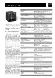
4.2 Connecting Diagram of the 100V Speaker Inputs<br />
The 100 V transformer for the CA 205 has 3 taps. These enable the speaker to be<br />
operated at 50 VA, 100 VA or 150 VA. Which tap is connected to which pin can be<br />
seen below.<br />
150VA transformer with taps for<br />
50VA, 100VA and 150VA<br />
50VA<br />
100VA<br />
1+<br />
2- IN 1-<br />
150VA 2+<br />
0<br />
all pins parallel to out<br />
KLING & FREITAG GMBH ©1995-2005 Version 3.1, 08.11.2006 Page 8 of 22
User’s <strong>Manual</strong> CA 205<br />
Warning<br />
5. Instructions for Suspending the Speakers<br />
The speakers may only be suspended by trained specialised personnel.<br />
Please follow the accompanying safety and assembly instructions carefully as well<br />
as the required safety factors. Pay attention to the t<br />
corresponding national safety<br />
regulations.<br />
Speaker systems, whether single or connected to one another, must always be secured<br />
to a second separate point.<br />
Ensure that all connections are secured to prevent their detaching on their own and<br />
that only admissible statically tested and sufficiently sized connecting devices, ropes<br />
and chains are used.<br />
The M6 threads may only be used in combination with the speaker mount ‘Omnimount<br />
WA50’ as well as for securing and aligning the speakers.<br />
Do not mount any additional ional loads to the M6 thread inserts on the bottom of<br />
the speakers.<br />
KLING & FREITAG GMBH ©1995-2005 Version 3.1, 08.11.2006 Page 9 of 22
User’s <strong>Manual</strong> CA 205<br />
6. Mounting Instructions for Loudspeakers<br />
Mount the speakers securely. To avoid injury or damage, always be sure to mount the<br />
speakers securely so that they do not fall. Speakers, which are stacked, must be secured<br />
with securing straps. When laying the connecting cables, make sure that nobody<br />
can trip.<br />
The stability of stacked systems (also valid for the use of stands and distance rods!) is<br />
contingent upon the following stability requirement. These conditions must, therefore,<br />
be guaranteed by the user:<br />
Stacked systems may not fall over even if they are inclined by 10° in each direc-<br />
tion. If this requirement is not fulfilled, then it is necessary to take steps to<br />
achieve compliance. Possible measures include strapping it to an appropriate<br />
base structure or fastening it using safety straps.<br />
Warning<br />
6.1 Proper Arrangement of the Loudspeakers<br />
Be aware of the fact that the logical targeted alignment of this high quality speaker<br />
system can lead to a significant qualitative increase in the acoustic result. It is not<br />
possible to make generalities about the alignment of specific systems because the<br />
room has a substantial influence on the signal and the audible result.<br />
As a rule, the mid- and high-transducers of loudspeakers should be mounted above<br />
the audience's face value, so that the sound distribution cannot be shadowed.<br />
In many cases it is advisable to mount a loudspeaker higher, so that the sound will be<br />
distributed throughout the room more evenly. Low standing systems result in a<br />
greater difference in volume between front and back seats than higher standing system.<br />
Please note that this is only a general guideline and the best possible result may vary<br />
from room to room.<br />
To simulate the correct alignment of the speakers beforehand, there are various programs<br />
such as ‘Ease’ or ‘Ulysses’. The <strong>Kling</strong> & <strong>Freitag</strong> speaker system data is available<br />
for download on our website www.kling-freitag.d.<br />
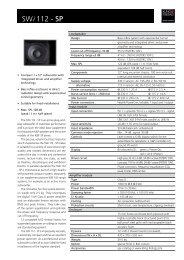
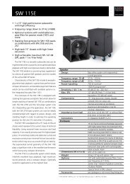
The following graphics will assist in making a rough estimate as to the distance range<br />
of the CA 205. The graphics only take into consideration the sum of the direct sound<br />
and not the influence of the room. Because of this there can, in some cases, be noticeable<br />
deviation.<br />
Distance range of SPL (direct sound level):<br />
-12 dB<br />
-6 dB<br />
0 dB<br />
-18 dB<br />
-24 dB -30 dB<br />
-34 dB<br />
2m 4m 8m 16m 32m 50m<br />
KLING & FREITAG GMBH ©1995-2005 Version 3.1, 08.11.2006 Page 10 of 22
User’s <strong>Manual</strong> CA 205<br />
7. Wiring<br />
The speaker is equipped with two parallel Speakon connectors.<br />
−<br />
−<br />
−<br />
Make sure that all units are switched off and all controls are turned down before<br />
connecting your CA 205 systems.<br />
We recommend the use of high-quality speaker cables provided by <strong>Kling</strong> & <strong>Freitag</strong>.<br />
For connections to the power amplifier inputs, please use 2-pin shielded microphone<br />
cable with high-quality connectors.<br />
− Avoid ground loops (see chapter 7.2 )<br />
−<br />
−<br />
−<br />
Please pay attention to the respective pin diagrams in this manual!<br />
Make sure that the +/- polarity of the speakers at the amplifier is correct. When<br />
simultaneously using power amplifiers from different manufacturers, be sure to use<br />
the correct specific pin configuration. It may be necessary to modify the pin configuration<br />
on the power amplifiers or on the connectors leading to them.<br />
Upon completing the wiring, ensure that the connected speaker channels are working<br />
in phase. To do so, use i.e. a phase checker. A phase error can also be recognized<br />
when the connected channels are used simultaneously. During simultaneous<br />
use the bass frequencies become notably quieter or the mid-frequencies such as<br />
voices cannot be located.<br />
− To avoid loss of power, the cables should have a minimum wire gauge of 2.5 mm² -<br />
more for longer cabled distances. A minimum wire gauge can be easily calculated<br />
with the following formula:<br />
Important<br />
Minimum Wire Gauge (mm²) =<br />
Required Cable Length (m)<br />
2 x Speaker Impedance (Ω)<br />
If several loudspeakers are connected, the signal can be linked through from one loudspeaker<br />
to the next. Please make sure that the total impedance of the loudspeakers R(Ω) is<br />
not lower than the minimal impedance indicated on the power amplifier.<br />
1/R 1<br />
+ 1/R 2<br />
+ 1/R 3<br />
+ ... = 1/R total<br />
7.1 Connecting the Speakon Connector to the Terminal<br />
1.<br />
2.<br />
2.<br />
1. 3.<br />
KLING & FREITAG GMBH ©1995-2005 Version 3.1, 08.11.2006 Page 11 of 22
User’s <strong>Manual</strong> CA 205<br />
7.2 Avoiding Ground Loops<br />
7.2.1 What is a Ground Loop?<br />
Every component of a P.A. or Hi-Fi System has its own internal 0 V reference (ground).<br />
This point is often connected to the protective earth connector (PE / Ground). If two<br />
or more units are connected to one another with a line level audio cable, there may<br />
be a ground connection through the ground of the power supply cable (yellow-green)<br />
as well as through the shielding of the audio cable. The voltage difference between<br />
these two ground points causes audible interference to come from the speaker.<br />
7.2.2 Avoiding Ground Loops<br />
If there is a loud humming or buzzing after the CA 205 system has been connected,<br />
then check that a "ground loop" has not been built into the system. Some power amplifiers<br />
and system controllers are equipped with a "Ground Lift" switch. Set these<br />
switches to the "Lift" position one after the other. If the noise is still audible, check if,<br />
−<br />
−<br />
the noise is caused by a ground loop before the power amplifiers / controllers<br />
(e.g. mixing console, effects or equalizers).<br />
the system or parts of the system are connected to an "unclean" power supply<br />
- meaning one, which is also running large motors, or lighting systems. An<br />
"un-clean" supply voltage, electrostatic and electromagnetic fields can cause a<br />
mal-function.<br />
Please observe the following basic rules:<br />
−<br />
−<br />
−<br />
−<br />
−<br />
Never!!! try to avoid a ground loop by disconnecting or taping the<br />
ground contact at the power connector! Extremely dangerous!<br />
If possible, only use high-quality audio appliances with balanced signal outputs<br />
and with power cables with PE connectors.<br />
Use high-quality cables with good shielding.<br />
The point of ground for all connected components should merge at one central<br />
point. The power connections should lead out in a radial manner from one<br />
point and not be linked from one unit to the next.<br />
When installing appliances that create strong electrostatic or electromagnetic<br />
fields (large transformers, switch-mode power supplies), maintain some distance<br />
from other audio appliances. In extreme cases, the only solution is to<br />
create a completely independent ‘audio ground’; in other cases, it is sufficient<br />
to connect a filter in front of the audio equipment.<br />
Warning<br />
KLING & FREITAG GMBH ©1995-2005 Version 3.1, 08.11.2006 Page 12 of 22
User’s <strong>Manual</strong> CA 205<br />
Warning<br />
8. Configurations and Connecting Diagrams<br />
• To protect the speakers from being destroyed and to avoid fire hazard, they should<br />
only be operated with professional power amplifiers with the following specifications:<br />
− integrated or preceding subsonic filter (approx. 30 Hz, min. 12 dB / octave)<br />
− integrated clipping limiter<br />
− maximum rated power 200W@16Ω (equivalent 800W@4Ω)<br />
8.1 CA 205 Systems in Full-Range Mode<br />
This mode of operation is ideal for speech applications and music applications without<br />
the need for a high bass content. Should more bass be needed, the bass level can be<br />
increased between 50 and 80 Hz at the mixing console.<br />
INPUT e.g. from<br />
mixer, AUX or<br />
Connector Panel<br />
OUTPUTS<br />
INPUT CH 2 INPUT CH 1<br />
- +<br />
- +<br />
CH 2 CH 1<br />
KLING & FREITAG GMBH ©1995-2005 Version 3.1, 08.11.2006 Page 13 of 22
User’s <strong>Manual</strong> CA 205<br />
8.2 Full Range Mode & Subwoofer with Crossover (XO)<br />
In this mode of operation you can easily realise applications, where a higher bass level<br />
is needed.<br />
Recommended combinations of CA Systems, as described here, with K&F subwoofers:<br />
2 CA 205 systems: 1 - 2 x SW 112-XO<br />
2 - 4 CA 205 systems: 1 x SW 115D-XO<br />
2 - 4 CA 205 systems: 1 x SW 115E-XO<br />
2 - 4 CA 205 systems: 1 x SW 118E-XO<br />
Switch To 'XO ON'<br />
Switch To 'XO ON'<br />
INPUT e.g. from<br />
mixer, AUX or<br />
Connector Panel<br />
INPUT CH 2 INPUT CH 1<br />
OUTPUTS<br />
- + - +<br />
CH 2 CH 1<br />
The switch ‘XO’ on the connecting terminal of the subwoofer must be at ‘XO ON’ or<br />
‘PASSIVE’ for this mode of operation.<br />
Connecting terminal 1 Connecting terminal 2<br />
KLING & FREITAG GMBH ©1995-2005 Version 3.1, 08.11.2006 Page 14 of 22
User’s <strong>Manual</strong> CA 205<br />
9. Operating the Speakers<br />
Important<br />
−<br />
−<br />
−<br />
−<br />
−<br />
−<br />
−<br />
−<br />
−<br />
−<br />
Switch off all equipment and turn down all level controls.<br />
Wire the CA 205 systems according to the wiring diagrams as shown before.<br />
Upon completing the wiring, ensure that the connected speaker channels are<br />
working in phase. To do so, use i.e. a phase checker. A phase error can also<br />
be recognized when the connected channels are used simultaneously. During<br />
simultaneous use the bass frequencies become notably quieter or the midfrequencies<br />
such as voices cannot be located.<br />
Now switch on the peripheral equipment first (mixing console, effects etc.),<br />
followed by the power amplifiers. Always use the before mentioned switching<br />
order. Otherwise switching noises may damage the system.<br />
If there is interference, turn off all appliances in the reverse order and check all<br />
cable connections (see chapter 7.2 ).<br />
Now put a low level signal into the system and check for the correct function<br />
of the system. In doing so, all amplifier input controls need to be turned off<br />
again. Now turn on the control for the left CA 205 system and check that the<br />
correct signal is coming out of the CA 205 system.<br />
Your system should now be ready for operation.<br />
Turning down the input level controls may not always prevent distortions in<br />
the input section of the power amplifier, especially if this section has a relatively<br />
low headroom. A clipping signal may not be displayed by the clipping<br />
indicator then. To prevent signal interruptions or damages to the speakers,<br />
turn the level controls of the power amplifier to the maximum position, if possible.<br />
The output level of the mixing console or the controller should be set to<br />
a level that doesn't overload the power amplifiers.<br />
When turning off the system, the input controls for the power amplifiers<br />
should be turned down first followed by the power switches of the amplifiers.<br />
After that, the other appliances can be turned off.<br />
The crossovers of the CA 205 systems are equipped with protection circuits for<br />
the 1’’ and 5’’ drivers. These circuits cut off the signal current when highly<br />
overloaded. If the high speaker turns off, reduce the volume. After a few seconds,<br />
it will turn back on automatically.<br />
KLING & FREITAG GMBH ©1995-2005 Version 3.1, 08.11.2006 Page 15 of 22
User’s <strong>Manual</strong> CA 205<br />
10. Crossover: Wiring Diagram CA 205<br />
Pin assignment Speakon NL4<br />
+ - / /<br />
‘IN’ 1+ 1- 2+ 2-<br />
‘OUT’ parallel with ‘IN’<br />
11. Touching Up Damage to Paint / Changing the Front Foam<br />
Although the PU structured paint used by KLING & FREITAG is impact proof and extremely<br />
resistant, we recommend using protective coverings or cases to help avoid<br />
damaging the paint during i.e. continuous mobile use. If paint damage occurs despite<br />
these precautions, it can be touched up by using commercial acrylic paint in the appropriate<br />
RAL colour of the speaker.<br />
To replace the filter foam, send the front grille incl. foam to KLING & FREITAG GmbH.<br />
Upon payment for expenses, the grille with the new covering will be returned.<br />
KLING & FREITAG GMBH ©1995-2005 Version 3.1, 08.11.2006 Page 16 of 22
User’s <strong>Manual</strong> CA 205<br />
12. Technical Specifications<br />
Loudspeaker<br />
Design<br />
2-way passive system, bass reflex tuning<br />
Frequency range -10 dB 85 Hz - 20 kHz<br />
Frequency range ±3 dB 120 Hz - 19 Hz<br />
Coverage angles (nominal) 110° x 60° (hor. x vert.)<br />
Directivity index (DI) 8 (+3.5/-1) 1 kHz - 13 kHz<br />
Power handling (nominal) 100 W nominal<br />
Max. SPL 118 db (SPL peak / 1 m)<br />
Components<br />
5‘‘ low-mid chassis (2x)<br />
1“ Aluminium horn tweeter with attached horn<br />
Crossover<br />
3.5 kHz 18 dB / octave<br />
self-resetting protection circuit for<br />
5‘‘ and 1‘‘ drivers<br />
Impedance<br />
16 Ω<br />
Connectors 2 x Speakon NL4MP (1+/1-)<br />
Enclosure<br />
Trapezoidal enclosure, 15 mm frame-reinforced<br />
Finnish birch Multiplex with highly resistant<br />
structured black or white paint (PU)<br />
5 x M 6 thread inserts<br />
compatible with various mounting equipment<br />
ball proof steel grille with exchangeable<br />
black or grey acoustic foam<br />
Dimensions (W x H x D) 169 x 437 x 186 mm<br />
Weight<br />
6.5 kg / 8.2 kg '100 Volt'<br />
Options<br />
'100 Volt' with 50/100/150 VA toroidal<br />
transformer,<br />
‘Terminal clamp’ instead of Speakon connector<br />
'Outdoor Mobile'<br />
'Special finish in RAL colours'<br />
Accessories<br />
see catalogue or visit www.kling-freitag.de<br />
KLING & FREITAG GMBH ©1995-2005 Version 3.1, 08.11.2006 Page 17 of 22
(d<br />
B)<br />
SP<br />
L<br />
Im<br />
pe<br />
da<br />
nc<br />
e<br />
(O<br />
User’s <strong>Manual</strong> CA 205<br />
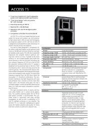
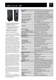
13. Measuring Charts<br />
Frequency response ‘on axis’<br />
100<br />
SPL (dB)<br />
IMPEDANCE (Ohm)<br />
316<br />
90<br />
100<br />
80<br />
31,6<br />
70<br />
10<br />
60<br />
3,16<br />
20 100 1000 10000 20000<br />
Fr equency (Hz)<br />
Frequency response ‘off axis’<br />
10<br />
Attenuation (dB)<br />
0<br />
-10<br />
-20<br />
0°<br />
10<br />
20<br />
30<br />
40<br />
-30<br />
20 100 1000 10000 20000<br />
Frequency (Hz)<br />
Vertical frequency response ‘off axis up’<br />
10<br />
Attenuation (dB)<br />
0<br />
-10<br />
-20<br />
0°<br />
10<br />
20<br />
30<br />
40<br />
-30<br />
20 100 1000 10000 20000<br />
Frequency (Hz)<br />
KLING & FREITAG GMBH ©1995-2005 Version 3.1, 08.11.2006 Page 18 of 22
User’s <strong>Manual</strong> CA 205<br />
Vertical frequency response ‘off axis down’<br />
10<br />
Attenuation (dB)<br />
0<br />
-10<br />
-20<br />
0°<br />
10<br />
20<br />
30<br />
40<br />
-30<br />
20 100 1000 10000 20000<br />
Frequency (Hz)<br />
Beamwidth<br />
360<br />
-6dB Beamwidth (degrees)<br />
300<br />
240<br />
180<br />
120<br />
60<br />
Horizontal<br />
Vertical<br />
0<br />
20<br />
100 1000 10000 20000<br />
Frequency (Hz)<br />
Q-Index<br />
20<br />
100<br />
DirectivityI ndex (DI), dB<br />
10<br />
10<br />
Directivity Factor (Q)<br />
0<br />
1<br />
20 100 1000 10000 20000<br />
Frequency (Hz)<br />
KLING & FREITAG GMBH ©1995-2005 Version 3.1, 08.11.2006 Page 19 of 22
User’s <strong>Manual</strong> CA 205<br />
14. Dimensions<br />
169 mm<br />
[6.652"]<br />
Gewindeeinsatz<br />
M 6<br />
8°<br />
186 mm<br />
[7.323"]<br />
Gewindeeinsatz<br />
M 6<br />
DIMENSIONS<br />
123.6 mm<br />
[4.867"]<br />
128 mm<br />
[5.039"]<br />
166 mm<br />
[6.530"]<br />
25 mm<br />
[0.984"]<br />
437 mm<br />
[17.205"]<br />
183 mm<br />
[7.207"]<br />
76 mm<br />
[2.994"]<br />
130.2 mm<br />
[5.126"]<br />
KLING & FREITAG GMBH ©1995-2005 Version 3.1, 08.11.2006 Page 20 of 22
User’s <strong>Manual</strong> CA 205<br />
15. Accessories<br />
Adjustable speaker mount CA 205 U-mount CA 205<br />
Wall and ceiling mount Mounting adapter TV-spigot adapter<br />
'Omnimount’<br />
Pipe Clamp TV-spigot Eyebolt<br />
M8 x 20<br />
Further information is available in our downloadable catalogue at:<br />
www.kling-freitag.de<br />
KLING & FREITAG GMBH ©1995-2005 Version 3.1, 08.11.2006 Page 21 of 22
User’s <strong>Manual</strong> CA 205<br />
16. Regulations for Disposal<br />
16.1 Germany:<br />
It is not allowed to dispose of used electrical equipment as domestic waste.<br />
But please do not dispose of them at official collecting points for recycling either!<br />
All <strong>Kling</strong> & <strong>Freitag</strong> products are plain business-to-business (B2B) products. Disposal of<br />
<strong>Kling</strong> & <strong>Freitag</strong> products labelled with a waste bin sign have thus to be disposed of by<br />
<strong>Kling</strong> & <strong>Freitag</strong> alone. Please call <strong>Kling</strong> & <strong>Freitag</strong> at the number stated below if you<br />
have a <strong>Kling</strong> & <strong>Freitag</strong> product to be disposed. We will offer you a straightforward<br />
and professional disposal not affecting costs.<br />
If there is no dustbin sign on one of your <strong>Kling</strong> & <strong>Freitag</strong> products, because they have<br />
been sold before March 2006 then by law the owner is in charge of the disposal. For<br />
these we will be happy to assist and offer you proper ways of disposal.<br />
Telephone number to call about the disposal of used <strong>Kling</strong> & <strong>Freitag</strong> products:<br />
+49 (511)-96 99 7-0<br />
Explanation:<br />
With the ElektroG (law relating to electrical and electronic equipment and appliances)<br />
we have complied with the EU-directive on waste electrical and electronic equipment<br />
(WEEE, 2002/96/EC)<br />
The <strong>Kling</strong> & <strong>Freitag</strong> AG has thus labelled all products mentioned in the WEEE from<br />
03/24/2006 onwards with a sign with a crossed out waste bin and a white bar below.<br />
This sign indicates that the disposal into the domestic waste is prohibited and that the<br />
product has been put into circulation at the 03/24/2006 earliest.<br />
The <strong>Kling</strong> & <strong>Freitag</strong> GmbH has been legally registered as a manufacturer with the<br />
registration office EAR. Our WEEE Registration-Nr. is: DE64110372<br />
For the German Registration office EAR we have accredited that our products are sole<br />
B2B products.<br />
16.2 EU, Norway, Island, and Liechtenstein (not Germany):<br />
It is not allowed to dispose of used electrical equipment as domestic waste.<br />
The <strong>Kling</strong> & <strong>Freitag</strong> AG has thus labelled all products coming from EU-Member countries<br />
as well as Norway, Island and Liechtenstein (except Germany) mentioned in the<br />
WEEE from 08/13/2005 onwards with a sign with a crossed out waste bin and a white<br />
bar below. This sign indicates that the disposal into the domestic waste is prohibited<br />
and that the product has been put into circulation at the 08/13/2005 earliest.<br />
Unfortunately the European directive WEEE has been complied with implementing<br />
different national provisions of law throughout all member countries, which makes it<br />
impossible for us to offer consistent solutions for the disposal throughout Europe.<br />
Responsible for complying with these provisions of law is the local distributor (importer)<br />
of each country.<br />
For proper disposition of used products in accordance with these local provisions in<br />
the mentioned countries of the European Union (except Germany) please ask your<br />
local dealer or the local authorities.<br />
16.3 Other countries<br />
For proper disposition of used products in accordance with local provisions in other<br />
countries please ask your local dealer or the local authorities.<br />
KLING & FREITAG GMBH ©1995-2005 Version 3.1, 08.11.2006 Page 22 of 22