Instruction manual, SPT and MPT 31x series transponders
Instruction manual, SPT and MPT 31x series transponders
Instruction manual, SPT and MPT 31x series transponders

You also want an ePaper? Increase the reach of your titles
YUMPU automatically turns print PDFs into web optimized ePapers that Google loves.
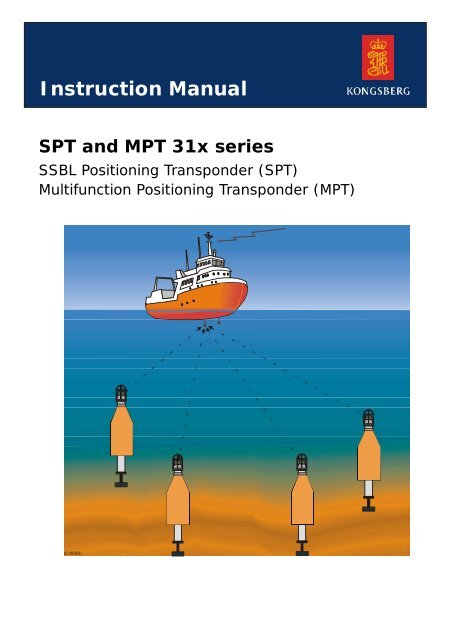
<strong>Instruction</strong> Manual<br />
<strong>SPT</strong><strong>and</strong><strong>MPT</strong><strong>31x</strong><strong>series</strong><br />
SSBL Positioning Transponder (<strong>SPT</strong>)<br />
Multifunction Positioning Transponder (<strong>MPT</strong>)<br />
(Cd5953)
<strong>SPT</strong> <strong>and</strong> <strong>MPT</strong> <strong>31x</strong> <strong>series</strong><br />
SSBL Positioning Transponder (<strong>SPT</strong>)<br />
Multifunction Positioning Transponder<br />
(<strong>MPT</strong>)<br />
<strong>Instruction</strong> Manual
Document history<br />
Rev Date Written by Checked by Approved by<br />
O<br />
Copyright<br />
25.06.2010 IJG SER JEF<br />
© 2010 Kongsberg Maritime AS. All rights reserved. The information contained in this<br />
document remains the sole property of Kongsberg Maritime. No part of this document<br />
may be copied or reproduced in any form or by any means, <strong>and</strong> the information<br />
contained within it is not to be communicated to a third party, without the prior written<br />
consent of Kongsberg Maritime.<br />
Disclaimer<br />
Kongsberg Maritime endeavors to ensure that all information in this document is<br />
correct <strong>and</strong> fairly stated, but does not accept liability for any errors or omission.<br />
Warning<br />
The equipment to which this <strong>manual</strong> applies must only be used for the purpose for<br />
which it was designed. Improper use or maintenance may cause damage to the<br />
equipment <strong>and</strong>/or injury to personnel. The user must be familiar with the contents of<br />
the appropriate <strong>manual</strong>s before attempting to operate or work on the equipment.<br />
Kongsberg Maritime disclaims any responsibility for damage or injury caused by<br />
improper installation, use or maintenance of the equipment.<br />
Support<br />
All Kongsberg Maritime products:<br />
Phone 24 hour: +47 815 35 355<br />
E-mail: km.support@kongsberg.com<br />
HiPAP, HPR, Transponder <strong>and</strong> ACS:<br />
Phone 24 hour: +47 992 03 808<br />
E-mail: km.support.hpr@kongsberg.com<br />
Kongsberg Maritime AS<br />
Str<strong>and</strong>promenaden 50<br />
P.O.Box 111<br />
N-3191 Horten,<br />
Norway<br />
Telephone: +47 33 02 38 00<br />
Telefax: +47 33 04 44 24<br />
www.kongsberg.com<br />
E-mail: subsea@kongsberg.com
<strong>Instruction</strong> Manual<br />
Remarks<br />
The reader<br />
The installation information in this <strong>manual</strong> is intended for the design <strong>and</strong> installation<br />
engineers at the shipyard performing the installation. The information is supplied as the<br />
basis for the shipyard’s own installation drawings applicable to the vessel. On<br />
completion of the installation, this <strong>manual</strong> must be kept on the vessel for reference<br />
purposes during system maintenance.<br />
The operator information in this <strong>manual</strong> is intended to be used by the system operator.<br />
He/she should be experienced in the operation of positioning systems, or should have<br />
attended a Kongsberg Maritime training course.<br />
The maintenance information in this <strong>manual</strong> is intended to be used by a trained<br />
maintenance technician or engineer, with experience of electronic <strong>and</strong> digital circuitry,<br />
computers <strong>and</strong> electromechanical design. The level of information is based on<br />
Kongsberg Maritime’s maintenance philosophy: The onboard technical personnel shall,<br />
with the help of the documentation <strong>and</strong> the system’s built-in test functions, be able to<br />
identify malfunctions, locate the fault, <strong>and</strong> replace major parts, modules <strong>and</strong><br />
components on the “Line Replaceable Unit” (LRU) level. He/she will however not<br />
attempt to repair the LRUs.<br />
160820/O I
<strong>SPT</strong> <strong>and</strong> <strong>MPT</strong> <strong>31x</strong> <strong>series</strong><br />
HIGH VOLTAGE SAFETY WARNING<br />
The voltages used to power this equipment are potentially lethal.<br />
Even 110 volts can kill.<br />
Whenever possible, the following precautionary measures<br />
should be taken before any work is carried out inside the<br />
equipment:<br />
Switch off all high-voltage power supplies.<br />
Check the operation of any door interlocks <strong>and</strong> any other<br />
safety devices.<br />
Completely discharge all high-voltage capacitors.<br />
It should be noted that interlocks <strong>and</strong> safety devices are<br />
normally located only at regular access points, <strong>and</strong> high voltages<br />
may be exposed during dismantling.<br />
Caution<br />
Never work alone on high-voltage equipment! Refer to<br />
general safety procedures.<br />
II 160820/O
<strong>Instruction</strong> Manual<br />
Contents<br />
1 ABOUT THIS MANUAL ........................................................................................ 1<br />
Manual content ........................................................................................................... 1<br />
Abbreviations ............................................................................................................. 1<br />
2 BASIC TRANSPONDER INFORMATION ......................................................... 2<br />
How to h<strong>and</strong>le a transponder ...................................................................................... 2<br />
General transponder description ................................................................................ 2<br />
Transponder identification ......................................................................................... 3<br />
EEx transponder classification ................................................................................... 4<br />
Applications ............................................................................................................... 5<br />
<strong>SPT</strong> specific applications ................................................................................ 5<br />
<strong>MPT</strong> specific applications .............................................................................. 6<br />
HPR <strong>and</strong> HiPAP compatibility................................................................................... 6<br />
Available <strong>transponders</strong> ............................................................................................... 6<br />
Special modules ......................................................................................................... 7<br />
Transponder model identification principles ............................................................. 8<br />
Transponder models description ................................................................................ 9<br />
Basic models ................................................................................................... 9<br />
Versions ........................................................................................................ 10<br />
Fibre optic gyrocompass transponder ...................................................................... 12<br />
Beam patterns ........................................................................................................... 13<br />
Auxiliary equipment ................................................................................................. 15<br />
3 TECHNICAL SPECIFICATIONS ....................................................................... 16<br />
Source level <strong>and</strong> receiver sensitivity ........................................................................ 16<br />
Common transponder specifications ........................................................................ 16<br />
Release units ............................................................................................................. 17<br />
Sensors ..................................................................................................................... 17<br />
Pressure <strong>and</strong> temperature sensor ................................................................... 17<br />
Compass sensor (magnetic) .......................................................................... 17<br />
Inclinometer sensor ....................................................................................... 18<br />
Aluminium <strong>transponders</strong> .......................................................................................... 18<br />
Version/R <strong>and</strong> /DTR ..................................................................................... 18<br />
Version/H ...................................................................................................... 19<br />
Version/E ...................................................................................................... 19<br />
Version/SIE .................................................................................................. 19<br />
160820/O III
<strong>SPT</strong> <strong>and</strong> <strong>MPT</strong> <strong>31x</strong> <strong>series</strong><br />
Version/SiH .................................................................................................. 19<br />
Version/SiHE ................................................................................................ 19<br />
Version/S <strong>and</strong> RS.......................................................................................... 19<br />
Stainless steel <strong>transponders</strong> ...................................................................................... 20<br />
Version/DT ................................................................................................... 20<br />
Version/L-St ................................................................................................. 20<br />
Version/I-St .................................................................................................. 20<br />
Version/EEx .................................................................................................. 21<br />
Version/EEx 90 ............................................................................................. 21<br />
Batteries .................................................................................................................... 21<br />
Battery weight ............................................................................................... 21<br />
Lithium battery label .................................................................................... 22<br />
External batteries ...................................................................................................... 23<br />
Battery unit L24 ............................................................................................ 23<br />
Subsea <strong>SPT</strong>/<strong>MPT</strong> battery unit ...................................................................... 23<br />
Octans module .......................................................................................................... 23<br />
Compass (fibre optic gyrocompass) ............................................................. 24<br />
External connectors <strong>and</strong> cables ................................................................................ 24<br />
Connectors .................................................................................................... 24<br />
Subsea <strong>SPT</strong>/<strong>MPT</strong> battery unit ...................................................................... 26<br />
Floating collars ......................................................................................................... 27<br />
Guiding collars ......................................................................................................... 27<br />
Mounting brackets .................................................................................................... 27<br />
4 SAFETY INFORMATION FOR TRANSPONDER AND TRANSPONDER<br />
BATTERY ...................................................................................................................... 28<br />
Identification of the products <strong>and</strong> company ............................................................. 28<br />
Product name ................................................................................................ 28<br />
Range of products ......................................................................................... 28<br />
Company address .......................................................................................... 29<br />
Emergency contact ....................................................................................... 29<br />
Composition <strong>and</strong> information on ingredients ........................................................... 29<br />
Battery chemistry .......................................................................................... 29<br />
Battery weight <strong>and</strong> lithium content .............................................................. 30<br />
Battery cell manufacturers/types .................................................................. 30<br />
Battery design ............................................................................................... 30<br />
Hazards identification .............................................................................................. 31<br />
Danger of explosions .................................................................................... 31<br />
IV 160820/O
<strong>Instruction</strong> Manual<br />
Noxious gases ............................................................................................... 32<br />
First-aid measures .................................................................................................... 32<br />
Fire-fighting measures ............................................................................................. 32<br />
Accidental release measures .................................................................................... 33<br />
H<strong>and</strong>ling <strong>and</strong> storage ................................................................................................ 33<br />
Recovering a “functioning” transponder ...................................................... 33<br />
Recovering a “failing” transponder .............................................................. 34<br />
H<strong>and</strong>ling a heated or self-heated transponder .............................................. 34<br />
H<strong>and</strong>ling a transponder if relief valve opens ................................................ 34<br />
Opening a transponder with defect/possible defect battery .......................... 35<br />
Opening a “functioning” transponder ........................................................... 35<br />
H<strong>and</strong>ling heated or warm separate battery ................................................... 36<br />
H<strong>and</strong>ling <strong>transponders</strong> <strong>and</strong> separate transponder batteries in case of an<br />
external fire ................................................................................................... 36<br />
Storage .......................................................................................................... 36<br />
Exposure controls <strong>and</strong> personals protection ............................................................. 37<br />
Physical <strong>and</strong> chemical properties ............................................................................. 37<br />
Stability <strong>and</strong> reactivity ............................................................................................. 37<br />
Toxicological information ........................................................................................ 38<br />
Ecological information ............................................................................................. 38<br />
Disposal considerations ............................................................................................ 38<br />
Transport information .............................................................................................. 38<br />
Regulatory information ............................................................................................ 39<br />
Other information ..................................................................................................... 39<br />
5 TRANSPONDER SETUP AND OPERATION ................................................... 40<br />
System set-up ........................................................................................................... 40<br />
Pre-deployment checks ............................................................................................ 41<br />
Mounting .................................................................................................................. 41<br />
Mounting an EEx transponder ...................................................................... 41<br />
Deployment .............................................................................................................. 41<br />
Release mechanism ....................................................................................... 42<br />
Ready for operation .................................................................................................. 42<br />
Positioning of a transponder ..................................................................................... 42<br />
Operation .................................................................................................................. 43<br />
Special operation instructions ....................................................................... 43<br />
Transponder in use ................................................................................................... 43<br />
’Functioning’-’Failing’-’Unknown’ ............................................................. 43<br />
160820/O V
<strong>SPT</strong> <strong>and</strong> <strong>MPT</strong> <strong>31x</strong> <strong>series</strong><br />
Sensor information ................................................................................................... 43<br />
DT sensor ...................................................................................................... 43<br />
Compass sensor (magnetic) .......................................................................... 44<br />
H ................................................................................................................... 44<br />
SiH ................................................................................................................ 44<br />
Octans module orientation ....................................................................................... 45<br />
Recovery .................................................................................................................. 45<br />
Release mechanism .................................................................................................. 46<br />
Setting the release mechanism ...................................................................... 48<br />
Storage .......................................................................................................... 48<br />
6 BATTERIES ........................................................................................................... 50<br />
Battery layout ........................................................................................................... 51<br />
Battery specification ................................................................................................. 51<br />
Battery replacement ................................................................................................. 51<br />
Battery lifetime at operation ..................................................................................... 52<br />
Lithium battery packs ............................................................................................... 53<br />
Lithium battery storage ................................................................................. 56<br />
Alkaline battery pack ............................................................................................... 56<br />
Alkaline battery storage ................................................................................ 57<br />
Rechargeable battery pack ....................................................................................... 58<br />
Battery unit L24 ....................................................................................................... 59<br />
Subsea <strong>SPT</strong>/<strong>MPT</strong> battery unit .................................................................................. 59<br />
How to mount the transponder battery ..................................................................... 59<br />
How to connect the transponder battery ................................................................... 60<br />
How to replace a transponder battery ....................................................................... 62<br />
How to replace the battery pack for the Battery unit L24 ........................................ 63<br />
How to replace the battery pack for the Subsea <strong>SPT</strong>/<strong>MPT</strong> battery unit .................. 63<br />
7 TRANSPONDER CONFIGURATION ............................................................... 64<br />
Frequency b<strong>and</strong> ........................................................................................................ 64<br />
Acoustic telemetry -basics ....................................................................................... 65<br />
Switch settings -basics ............................................................................................. 65<br />
HPR 400/HiPAP channels ........................................................................................ 66<br />
HPR 400 system ........................................................................................... 66<br />
HiPAP system ............................................................................................... 66<br />
Acoustic coding principle ............................................................................. 66<br />
HPR 400 channels <strong>and</strong> positioning frequencies ........................................... 66<br />
HPR 300 channels .................................................................................................... 67<br />
VI 160820/O
<strong>Instruction</strong> Manual<br />
HPR 300 comm<strong>and</strong> function ........................................................................ 68<br />
HPR 300 frequencies <strong>and</strong> switch settings ..................................................... 68<br />
8 MAINTENANCE ................................................................................................... 70<br />
Preventive maintenance ........................................................................................... 70<br />
Maintenance for explosion-protected units .............................................................. 71<br />
Testing the transponder ............................................................................................ 71<br />
How to open a transponder ...................................................................................... 71<br />
Aluminium <strong>transponders</strong> .............................................................................. 72<br />
Stainless steel <strong>transponders</strong> .......................................................................... 74<br />
How to replace a transponder circuit board ............................................................. 76<br />
Rx board, Tx board <strong>and</strong> Microcontroller board ............................................ 76<br />
Rx-amplifier matching board ........................................................................ 77<br />
How to replace the transducer .................................................................................. 77<br />
Aluminium <strong>transponders</strong> .............................................................................. 77<br />
Stainless steel <strong>transponders</strong> .......................................................................... 77<br />
How to remove the bottom end cap / release unit .................................................... 78<br />
How to assemble a transponder ................................................................................ 78<br />
Calibration ................................................................................................................ 79<br />
Compass <strong>transponders</strong> .................................................................................. 80<br />
Transducer h<strong>and</strong>ling ................................................................................................. 80<br />
Source level adjustment ........................................................................................... 80<br />
Octans module .......................................................................................................... 80<br />
9 MAIN PARTS ......................................................................................................... 81<br />
Transducer ................................................................................................................ 82<br />
Depth <strong>and</strong> temperature sensors ................................................................................ 83<br />
Housing .................................................................................................................... 83<br />
Bottom end cap / Release unit .................................................................................. 83<br />
Circuit boards ........................................................................................................... 84<br />
Transmitter board (Tx) ................................................................................. 84<br />
Receiver board (Rx) ...................................................................................... 85<br />
Rx amplifier matching board ........................................................................ 85<br />
Microcontroller board ................................................................................... 86<br />
Switches ........................................................................................................ 87<br />
Motherboard ................................................................................................. 87<br />
10 AUXILIARY EQUIPMENT ................................................................................. 89<br />
Anchor-weight .......................................................................................................... 89<br />
160820/O VII
<strong>SPT</strong> <strong>and</strong> <strong>MPT</strong> <strong>31x</strong> <strong>series</strong><br />
Floating rope ............................................................................................................ 89<br />
Auxiliary equipment supplied by Kongsberg Maritime ........................................... 89<br />
Floating collar ............................................................................................... 90<br />
Mounting brackets ........................................................................................ 90<br />
Guiding collar ............................................................................................... 92<br />
11 SPARE PARTS ....................................................................................................... 94<br />
Codes used ............................................................................................................... 94<br />
Accessories ............................................................................................................... 95<br />
Sensors ..................................................................................................................... 96<br />
Batteries .................................................................................................................... 96<br />
Extractor tool ............................................................................................................ 97<br />
<strong>SPT</strong> 314 basic transponder ....................................................................................... 97<br />
<strong>SPT</strong> 314 basic transponder – Exploded view ............................................... 99<br />
<strong>SPT</strong> 314/R transponder .......................................................................................... 100<br />
<strong>SPT</strong> 314/R transponder – Exploded view ................................................... 102<br />
<strong>SPT</strong> 314/I transponder ............................................................................................ 103<br />
<strong>SPT</strong> 314/I transponder – Exploded view .................................................... 105<br />
<strong>SPT</strong> 319 basic transponder ..................................................................................... 106<br />
<strong>SPT</strong> 319 basic transponder – Exploded view ............................................. 108<br />
<strong>SPT</strong> 319/R transponder .......................................................................................... 109<br />
<strong>SPT</strong> 319/R transponder – Exploded view ................................................... 111<br />
<strong>SPT</strong> 319/H transponder .......................................................................................... 112<br />
<strong>SPT</strong> 319/H transponder - Exploded ............................................................ 114<br />
<strong>SPT</strong> 319/I-St transponder ....................................................................................... 115<br />
<strong>SPT</strong> 319/I-St transponder – Exploded view ............................................... 117<br />
<strong>SPT</strong> 319/I transponder ............................................................................................ 118<br />
<strong>SPT</strong> 319/I transponder – Exploded view .................................................... 120<br />
<strong>SPT</strong> 319/S transponder ........................................................................................... 120<br />
<strong>SPT</strong> 319/S transponder – Exploded view ................................................... 123<br />
<strong>SPT</strong> 319/E transponder .......................................................................................... 124<br />
<strong>SPT</strong> 319/E transponder – Exploded view ................................................... 126<br />
<strong>SPT</strong> 319/SIE transponder ....................................................................................... 127<br />
<strong>SPT</strong> 319/SIE transponder – Exploded view ............................................... 129<br />
<strong>SPT</strong> 319/SiHE transponder .................................................................................... 130<br />
<strong>SPT</strong> 319/SiHE transponder – Exploded view ............................................. 132<br />
<strong>MPT</strong> 313 basic transponder ................................................................................... 133<br />
<strong>MPT</strong> 313 basic transponder – Exploded view ............................................ 135<br />
VIII 160820/O
<strong>Instruction</strong> Manual<br />
<strong>MPT</strong> 313/H transponder ......................................................................................... 136<br />
<strong>MPT</strong> 313/H transponder – Exploded view ................................................. 138<br />
<strong>MPT</strong> 313/R transponder ......................................................................................... 139<br />
<strong>MPT</strong> 313/R transponder – Exploded view ................................................. 141<br />
<strong>MPT</strong> 313/S transponder ......................................................................................... 142<br />
<strong>MPT</strong> 313/RS transponder ....................................................................................... 142<br />
<strong>MPT</strong> 313/RS transponder – Exploded view ............................................... 144<br />
<strong>MPT</strong> 313/SiH transponder ..................................................................................... 145<br />
<strong>MPT</strong> 313/SiH transponder – Exploded view .............................................. 147<br />
Magnetic release mechanism ................................................................................. 148<br />
<strong>MPT</strong> 319 basic transponder ................................................................................... 148<br />
<strong>MPT</strong> 319 basic transponder – Exploded view ............................................ 150<br />
<strong>MPT</strong> 319/DT transponder ...................................................................................... 151<br />
Accessories ................................................................................................. 152<br />
<strong>MPT</strong> 319/DT transponder – Exploded view ............................................... 153<br />
<strong>MPT</strong> 319/R transponder ......................................................................................... 154<br />
<strong>MPT</strong> 319/R transponder – Exploded view ................................................. 156<br />
<strong>MPT</strong> 319/DTR transponder .................................................................................... 157<br />
<strong>MPT</strong> 319/DTR transponder – Exploded view ............................................ 159<br />
<strong>MPT</strong> 319/DT-St transponder .................................................................................. 160<br />
<strong>MPT</strong> 319/DT-St transponder – Exploded view .......................................... 162<br />
<strong>MPT</strong> 319/L-St transponder .................................................................................... 163<br />
<strong>MPT</strong> 319/L-St transponder – Exploded view ............................................. 165<br />
<strong>MPT</strong> 319/SiH transponder ..................................................................................... 166<br />
<strong>MPT</strong> 319/SiH transponder – Exploded view .............................................. 168<br />
Octans module ........................................................................................................ 169<br />
Octans module - Drawing <strong>and</strong> wiring ......................................................... 170<br />
Battery unit L24 ..................................................................................................... 171<br />
Battery unit L24 – Subsea battery unit ....................................................... 172<br />
Subsea <strong>SPT</strong>/<strong>MPT</strong> battery unit ................................................................................ 173<br />
Subsea <strong>SPT</strong>/<strong>MPT</strong> battery unit – Exploded view ........................................ 174<br />
<strong>MPT</strong> 316/DT EEx transponder .............................................................................. 175<br />
<strong>MPT</strong> 316/DT EEx transponder – Exploded view ....................................... 177<br />
<strong>MPT</strong> 316/EEx 90 transponder ................................................................................ 178<br />
<strong>MPT</strong> 316/EEx 90 transponder – Exploded view ........................................ 180<br />
12 DRAWING FILE ................................................................................................. 181<br />
Drawings ................................................................................................................ 182<br />
160820/O IX
<strong>SPT</strong> <strong>and</strong> <strong>MPT</strong> <strong>31x</strong> <strong>series</strong><br />
<strong>SPT</strong> 314 transponder – outline dimensions ............................................................ 183<br />
<strong>SPT</strong> 314/R transponder – outline dimensions ........................................................ 184<br />
<strong>SPT</strong> 319/S transponder – outline dimensions ........................................................ 185<br />
Split TD 319 w/4-pin Gisma – outline dimensions ................................................ 186<br />
<strong>SPT</strong> 319/E transponder – outline dimensions ........................................................ 187<br />
<strong>SPT</strong> 319/SIE transponder – outline dimensions ..................................................... 188<br />
<strong>SPT</strong> 319/SiHE transponder – outline dimensions .................................................. 189<br />
<strong>MPT</strong> 313 transponder – outline dimensions .......................................................... 190<br />
<strong>MPT</strong> 313/R transponder – outline dimensions ....................................................... 191<br />
<strong>MPT</strong> 313/S <strong>and</strong> <strong>MPT</strong> 313/RS transponder – outline dimensions .......................... 192<br />
<strong>MPT</strong> 313/S <strong>and</strong> <strong>MPT</strong> 313/RS transducers– outline dimensions ............................ 193<br />
<strong>MPT</strong> 313/SiH transponder – outline dimensions ................................................... 194<br />
<strong>MPT</strong> 319 <strong>and</strong> <strong>SPT</strong> 319 transponder – outline dimensions ..................................... 195<br />
<strong>MPT</strong> 319/R <strong>and</strong> <strong>SPT</strong> 319/R transponder – outline dimensions ............................. 196<br />
<strong>MPT</strong> 319/DT-St transponder – outline dimensions ............................................... 197<br />
<strong>MPT</strong> 319/L-St transponder – outline dimensions .................................................. 198<br />
<strong>MPT</strong> 319/SiH transponder – outline dimensions ................................................... 199<br />
<strong>MPT</strong> 316/EEx-St transponder – outline dimensions .............................................. 200<br />
<strong>MPT</strong> 316/EEx 90 transponder – outline dimensions ............................................. 201<br />
Floating collar for <strong>SPT</strong>/<strong>MPT</strong> <strong>transponders</strong> 1000 m - outline dimensions ............. 202<br />
Guiding collar for <strong>SPT</strong>/<strong>MPT</strong> <strong>transponders</strong> 1000 m - outline dimensions ............. 203<br />
Transponder pedestal ............................................................................................. 204<br />
Subsea battery pack – outline dimensions ............................................................. 205<br />
Octans module - outline dimensions ...................................................................... 206<br />
Transponder cable .................................................................................................. 207<br />
13 INDEX ................................................................................................................... 208<br />
X 160820/O
About this <strong>manual</strong><br />
1 ABOUT THIS MANUAL<br />
Manual content<br />
This <strong>manual</strong> describes all the <strong>SPT</strong> <strong>and</strong> <strong>MPT</strong> <strong>transponders</strong>, for<br />
medium deep water use -1000 m rated.<br />
It provides general information, technical specifications,<br />
operating instructions, maintenance procedures <strong>and</strong> battery<br />
information <strong>and</strong> safety procedures. It also includes spare parts<br />
lists <strong>and</strong> outline dimension drawings for each of the transponder<br />
units.<br />
Warning<br />
Some of the <strong>transponders</strong> described in this<br />
<strong>manual</strong> are explosion-protected electronic units<br />
of the type “Flameproof enclosure”!<br />
Abbreviations<br />
BOP<br />
HiPAP<br />
HPR<br />
LBL<br />
MF<br />
<strong>MPT</strong><br />
N/A<br />
ROV<br />
<strong>SPT</strong><br />
SSBL<br />
TP<br />
TD<br />
Blow Out Preventer<br />
High Precision Acoustic Positioning<br />
Hydroacoustic Position Reference<br />
Long Base Line<br />
Medium Frequency<br />
Multifunction Positioning Transponder<br />
Not Applicable<br />
Remotely Operated Vehicle<br />
SSBL Positioning Transponder<br />
Super Short Base Line<br />
Transponder<br />
Transducer<br />
160820/O 1
<strong>SPT</strong> <strong>and</strong> <strong>MPT</strong> <strong>31x</strong> <strong>series</strong><br />
2 BASIC TRANSPONDER INFORMATION<br />
The purpose of this chapter is to provide an overall description<br />
of the <strong>transponders</strong> included in this <strong>manual</strong>.<br />
Topics<br />
How to h<strong>and</strong>le a transponder - on page 2<br />
General transponder description - on page 2<br />
Transponder identification - on page 3<br />
EEx transponder classification - on page 4<br />
How to h<strong>and</strong>le a transponder<br />
Each transponder is normally delivered with separate battery.<br />
St<strong>and</strong>ard battery is a Lithium battery.<br />
Warning<br />
Due to safety rules, the transponder must be<br />
h<strong>and</strong>led with care! Refer to Safety information for<br />
transponder <strong>and</strong> transponder battery on page 28.<br />
Figure 1 Special precaution to avoid personnel injury<br />
General transponder description<br />
The <strong>SPT</strong> <strong>and</strong> <strong>MPT</strong> <strong>31x</strong> transponder <strong>series</strong> are designed for use<br />
with the HPR <strong>and</strong> HiPAP systems. The following are available:<br />
2 160820/O
Basic transponder information<br />
<strong>SPT</strong> 314 transponder <strong>series</strong><br />
<strong>SPT</strong> 319 transponder <strong>series</strong><br />
<strong>MPT</strong> 313 transponder <strong>series</strong><br />
<strong>MPT</strong> 316 transponder <strong>series</strong> (for use in EEX, zone 0)<br />
<strong>MPT</strong> 319 transponder <strong>series</strong><br />
Examples of the <strong>transponders</strong> are shown in figure on<br />
page 5.<br />
All models have an acoustic telemetry link for comm<strong>and</strong> <strong>and</strong><br />
data transfer.<br />
The transponder unit is designed with a modular construction<br />
such that the transducer, transponder electronics, battery pack<br />
<strong>and</strong> options (where applicable) can be replaced individually.<br />
A transponder is normally a self-contained unit, its power being<br />
provided from an internal battery pack.<br />
Most units are designed for ROV manipulator h<strong>and</strong>ling.<br />
The transponder may be secured to a subsea structure using<br />
mounting brackets, or fitted with an anchor weight <strong>and</strong> floating<br />
collar for location on the open seabed.<br />
Transponder identification<br />
An identification clamp ring is tightened around the transponder<br />
body. This ring is engraved with:<br />
Transponder name<br />
Transponder registration number<br />
Unique serial number<br />
Frequency channel<br />
Type of battery<br />
The figure shows an identification clamp ring for a transponder<br />
that uses channel 57 <strong>and</strong> includes a lithium battery. Name <strong>and</strong><br />
serial number is engraved on the other side.<br />
160820/O 3
<strong>SPT</strong> <strong>and</strong> <strong>MPT</strong> <strong>31x</strong> <strong>series</strong><br />
I<br />
II<br />
(Cd5976)<br />
Figure 2 Example of identification clamp ring<br />
If the TP configuration <strong>and</strong> battery is changed, the channel<br />
number (I) <strong>and</strong> the type of battery (II) can be altered by setting<br />
pegs into different holes in the clamp.<br />
EEx transponder classification<br />
The <strong>MPT</strong> 316 <strong>transponders</strong> are explosion protected electronic<br />
units of the types; EEx d IIB T6. The following units are<br />
available:<br />
<strong>MPT</strong> 316/DT EEx<br />
<strong>MPT</strong> 316/DT EEx 90<br />
Caution<br />
The units must be used as defined, <strong>and</strong> meet the<br />
requirements of EN 50 014 -50 020 or VDE0171<br />
Electronic apparatus for potentially explosive<br />
atmospheres respectively.<br />
4 160820/O
Basic transponder information<br />
Figure 3 Examples of <strong>SPT</strong> <strong>and</strong> <strong>MPT</strong> <strong>transponders</strong><br />
Applications<br />
On interrogation, all models will reply with either a single-or a<br />
multi-pulse response. The response information depends on the<br />
application. All <strong>SPT</strong> <strong>and</strong> <strong>MPT</strong> models can be used in the<br />
following applications:<br />
SSBL positioning<br />
Acoustic release<br />
Telemetry of sensor data<br />
Depth <strong>and</strong> temperature measurement<br />
<strong>SPT</strong> specific applications<br />
The following application can be used with the <strong>SPT</strong> only:<br />
Inclination measurement<br />
160820/O 5
<strong>SPT</strong> <strong>and</strong> <strong>MPT</strong> <strong>31x</strong> <strong>series</strong><br />
<strong>MPT</strong> specific applications<br />
The following applications can be used with the <strong>MPT</strong> only:<br />
LBL positioning<br />
Self positioning<br />
Range measuring<br />
HPR <strong>and</strong> HiPAP compatibility<br />
All the <strong>31x</strong> <strong>transponders</strong> are compatible with the Kongsberg<br />
Maritime HPR 400 MF <strong>and</strong> HiPAP systems.<br />
Available <strong>transponders</strong><br />
This <strong>manual</strong> covers the following <strong>transponders</strong> <strong>and</strong> special<br />
modules:<br />
Transponder <strong>series</strong> Model Housing Material<br />
<strong>SPT</strong> 314<br />
<strong>SPT</strong> 314 Base unit Aluminium<br />
<strong>SPT</strong> 314/R Release Aluminium<br />
<strong>SPT</strong> 314/I Inclinometer Aluminium<br />
<strong>SPT</strong> 319<br />
<strong>SPT</strong> 319 Bare unit Aluminium<br />
<strong>SPT</strong> 319/R Release Aluminium<br />
<strong>SPT</strong> 319/H Compass – magnetic Aluminium<br />
<strong>SPT</strong> 319/S Split transducer Aluminium<br />
<strong>SPT</strong> 319/I Inclinometer Aluminium<br />
<strong>SPT</strong> 319/I-St Inclinometer Stainless steel<br />
<strong>SPT</strong> 319/E With external battery Aluminium<br />
<strong>SPT</strong> 319/SIE Split transducer,<br />
Inclinometer <strong>and</strong><br />
Aluminium<br />
<strong>MPT</strong> 313<br />
<strong>SPT</strong><br />
319/SiHE<br />
external battery<br />
Serial interface for<br />
Octans module, Compass<br />
- magnetic <strong>and</strong><br />
external battery<br />
Aluminium<br />
<strong>MPT</strong> 313 Basic unit<br />
Aluminium<br />
(doughnut-shaped<br />
transducer)<br />
<strong>MPT</strong> 313/H Compass - magnetic Aluminium<br />
<strong>MPT</strong> 313/R Release Aluminium<br />
<strong>MPT</strong> 313/S Split transducer Aluminium<br />
6 160820/O
Basic transponder information<br />
Transponder <strong>series</strong> Model Housing Material<br />
<strong>MPT</strong> 313/RS Release <strong>and</strong> Split Aluminium<br />
transducer<br />
<strong>MPT</strong><br />
313/SiH<br />
Serial interface for<br />
Octans module, Compass<br />
- magnetic<br />
Aluminium<br />
<strong>MPT</strong> 319<br />
<strong>MPT</strong> 316<br />
<strong>MPT</strong> 319 Basic unit Aluminium<br />
<strong>MPT</strong> 319/DT Depth <strong>and</strong> Temperature Aluminium<br />
<strong>MPT</strong> 319/R Release Aluminium<br />
<strong>MPT</strong> Depth, Temperature <strong>and</strong> Aluminium<br />
319/DTR Release<br />
<strong>MPT</strong>/DT-St Depth <strong>and</strong> Temperature Stainless Steel<br />
<strong>MPT</strong> 319/L- Basic unit with long tube Stainless Steel<br />
St<br />
<strong>MPT</strong><br />
319/SiH<br />
<strong>MPT</strong> 316/<br />
<strong>MPT</strong> 316/<br />
Serial interface for<br />
Octans module, Compass<br />
- magnetic<br />
Depth <strong>and</strong> Temperature<br />
with explosionprotected<br />
electronic unit<br />
Basic unit with<br />
explosion-protected<br />
electronic unit <strong>and</strong> a 90<br />
angle transducer<br />
Aluminium<br />
Stainless Steel<br />
Stainless Steel<br />
Special modules<br />
Model Function Housing material<br />
Octans module Fibre optic gyrocompass Aluminium<br />
Battery unit L24<br />
External subsea battery<br />
unit for powering the<br />
Aluminium<br />
Octans module<br />
Subsea <strong>SPT</strong>/<strong>MPT</strong> battery<br />
unit<br />
External subsea <strong>SPT</strong>/<strong>MPT</strong><br />
battery unit for powering<br />
the <strong>SPT</strong> 319/E <strong>series</strong><br />
Aluminium<br />
160820/O 7
<strong>SPT</strong> <strong>and</strong> <strong>MPT</strong> <strong>31x</strong> <strong>series</strong><br />
Transponder model identification principles<br />
The transponder name consists of:<br />
Model name (three letters)<br />
Model number (three digits)<br />
Any options included (letters after the digits)<br />
Model name<br />
See example below.<br />
<strong>SPT</strong> = SSBL Positioning Transponder. <strong>MPT</strong> = Multifunction<br />
Positioning Transponder.<br />
Model number<br />
The three digits:<br />
Digit 1: frequency b<strong>and</strong><br />
Digit 2: depth rating<br />
Digit 3: beamwidth<br />
The following are available:<br />
1 st digit 2 nd digit 3 rd digit<br />
Frequency b<strong>and</strong> Depth rating Transducer beamwidth<br />
3 = 30 kHz 1 = 1000 m<br />
3 = + - 30º<br />
4 = + - 45º<br />
Options<br />
6 = + - 60º<br />
9 = + - 90º<br />
The combination of letters after the number describes the<br />
options contained in the unit. The following options are<br />
available:<br />
DT<br />
R<br />
I<br />
H<br />
E<br />
Depth <strong>and</strong> Temperature sensors<br />
Release mechanism<br />
Inclinometer (one unit)<br />
Heading magnetic compass<br />
External battery<br />
8 160820/O
Basic transponder information<br />
L<br />
S<br />
Si<br />
Long tube -indicates that the unit is longer<br />
than st<strong>and</strong>ard, to accommodate a larger<br />
battery<br />
Split transducer<br />
Serial interface<br />
EEx The unit meet the requirements of EN 50<br />
014 -50 020 or VDE0171 “Electrical<br />
apparatus for potentially explosive<br />
atmosphere” respectively<br />
EEx 90<br />
Housing material<br />
As described above, <strong>and</strong> the transducer is<br />
mounted at an angle of 90_ perpendicular<br />
to the longitudinal axes of the transponder<br />
Aluminium is st<strong>and</strong>ard housing material. If Stainless steel is<br />
used, the abbreviation “St” is added to the transponder name<br />
(see example below).<br />
Example: <strong>MPT</strong> 319/DT-St<br />
The example given (<strong>MPT</strong> 319/DT-St) therefore indicates that<br />
the transponder unit is an Multifunction Positioning<br />
Transponder, operating in the 30 kHz b<strong>and</strong>, rated to 1000 meters<br />
depth, with a ± 90º beam width, <strong>and</strong> including the Depth <strong>and</strong><br />
Temperature sensors. The housing material is stainless steel.<br />
Transponder models description<br />
Basic models<br />
<strong>SPT</strong> 314<br />
The <strong>SPT</strong> 314 can only operate as an SSBL transponder to<br />
provide positional information. It is equipped with a ± 45º<br />
beamwidth transducer. All <strong>SPT</strong> 314 models are based on this<br />
basic model.<br />
<strong>SPT</strong> 319<br />
The <strong>SPT</strong> 319 can only operate as an SSBL transponder to<br />
provide positional information. It is equipped with a ± 90º<br />
beamwidth transducer. All <strong>SPT</strong> 319 models are based on this<br />
basic model.<br />
160820/O 9
<strong>SPT</strong> <strong>and</strong> <strong>MPT</strong> <strong>31x</strong> <strong>series</strong><br />
<strong>MPT</strong> 313<br />
The <strong>MPT</strong> 313 transponder operates as either an SSBL or LBL<br />
transponder. It is equipped with a ± 30º beamwidth transducer.<br />
The transducer is “doughnut-shaped”, <strong>and</strong> provides a horizontal<br />
beam. All <strong>MPT</strong> 313 models are based on this basic model.<br />
<strong>MPT</strong> 319<br />
The <strong>MPT</strong> 319 transponder operates as either an SSBL or LBL<br />
transponder to provide positional information. It is equipped<br />
with a ± 90º beamwidth transducer. All <strong>MPT</strong> 319 models are<br />
based on this basic model.<br />
<strong>MPT</strong> 316<br />
The <strong>MPT</strong> 319 transponder operates as either an SSBL or LBL<br />
transponder to provide positional information. It is equipped<br />
with a ± 60º beamwidth transducer. The unit is explosionprotected,<br />
<strong>and</strong> it is equipped with stainless steel housing. All<br />
<strong>MPT</strong> 316 models are based on this basic model.<br />
Versions<br />
/DT<br />
The Depth <strong>and</strong> Temperature (DT) transponder is equipped<br />
with pressure <strong>and</strong> temperature sensors to measure:<br />
The depth at the position where the unit is moored.<br />
The temperature in the surrounding water.<br />
Note<br />
In the HPR 300 system only depth is obtainable.<br />
/R<br />
The Release mechanism (R) transponder is a recoverable unit<br />
fitted with an automatic release mechanism <strong>and</strong> a floating collar.<br />
This detaches the anchor weight on request from the HiPAP /<br />
HPR system. Once the transponder has been released, it will<br />
float to the surface where it can be recovered.<br />
You can reset the release-mechanism at the surface, <strong>and</strong> you can<br />
use the same unit many times in different areas. The anchor<br />
weight will be lost during the release-operation, so it will require<br />
replacement every time.<br />
10 160820/O
Basic transponder information<br />
/H<br />
The Compass, (H) transponder is equipped with a heading<br />
magnetic compass. This unit also has an inclinometer that can be<br />
read by telemetry. When used for positioning, only the compass<br />
values are achievable.<br />
/I<br />
The Inclinometer (I) transponder is equipped with one set of<br />
inclinometers set at 90 degrees to each other. It is used to<br />
measure <strong>and</strong> monitoring the angles of structures such as:<br />
/L<br />
Rise angle measurement on oil platforms.<br />
Monitoring underwater pipelines.<br />
Template levelling.<br />
The Long tube, (L) is a basic transponder equipped with a long<br />
housing of stainless steel, to incorporate a large battery.<br />
/S<br />
The Split housing <strong>and</strong> transducer transponder (S). The unit<br />
has separate housing (electronics unit) <strong>and</strong> transducer. The<br />
transducer has a 5 m long cable, to connect it to the housing.<br />
/SiH<br />
The <strong>MPT</strong> 313 <strong>and</strong> <strong>MPT</strong> 319/SiH is designed to interface the<br />
Octans module (fibre-optic gyro compass). It is also equipped<br />
with a heading magnetic compass.<br />
/E<br />
Refer to the /H version.<br />
The External battery, (E) transponder is equipped with<br />
connector for connection of an external battery.<br />
/SIE<br />
The <strong>SPT</strong> 319/SIE is designed with split transducer, inclinometer<br />
sensor <strong>and</strong> connector for external battery.<br />
/SiHE<br />
Refer to the /E version.<br />
The <strong>SPT</strong> 319/SiHE is designed to interface the Octans module<br />
(fibre-optic gyro compass). It is also equipped with a heading<br />
magnetic compass, <strong>and</strong> connector for external battery.<br />
160820/O 11
<strong>SPT</strong> <strong>and</strong> <strong>MPT</strong> <strong>31x</strong> <strong>series</strong><br />
Refer to the /H version.<br />
Refer to the /E version.<br />
/EEx<br />
The Explosive-protected (EEx) transponder. The unit is<br />
explosion-protected, <strong>and</strong> it is equipped with a stainless steel<br />
housing. It is classified as EEx d IIB T6.<br />
This is a completely encapsulated unit, <strong>and</strong> is not prepared for<br />
ROV installation or retrieval, as it has no protection-cage.<br />
The depth sensor (pressure) is at maximum scale at 500 m, but<br />
the transponder can be deployed down to 1000 m.<br />
/EEx 90<br />
The Explosive-protected with a 90 angle transducer (EEx90)<br />
transponder, is an explosion-protected unit, <strong>and</strong> the transducer is<br />
mounted at an angle of 90 perpendiculars on the longitudinal<br />
axes of the transponder. This transponder is to be used in an<br />
horizontal position. It is equipped with stainless steel housing.<br />
The transponder is equipped with a locking-pin at the top (see<br />
figure in the spare parts section), which is used to secure the<br />
transponder in position when deployed.<br />
Fibre optic gyrocompass transponder<br />
The <strong>MPT</strong> 313/SiH or the <strong>MPT</strong> 319/SiH together with the Octans<br />
module <strong>and</strong> the Battery unit L24, are a high performance truenorth<br />
seeking gyrocompass that takes no influence from<br />
magnetic fields.<br />
The transponder <strong>and</strong> the Octans module are connected by a<br />
serial line (RS-232) in a subsea cable, with Gisma connectors.<br />
The Octans module is powered by one or two purpose-built<br />
Battery units L24. The Battery units L24 <strong>and</strong> the Octans module<br />
are connected by subsea cables with Gisma connectors.<br />
Octans fibre optic gyrocompass, true-north seeking<br />
gyrocompass<br />
Magnetic compass, for backup.<br />
Note<br />
When this transponder is used for positioning, only the compass<br />
values are achievable. Roll <strong>and</strong> pitch can be read by telemetry.<br />
12 160820/O
Basic transponder information<br />
(Cd6981)<br />
Battery<br />
Battery<br />
Octans<br />
gyro<br />
Transponder<br />
Figure 4 Example of a <strong>MPT</strong>/SiH transponder with batteries <strong>and</strong><br />
gyrocompass<br />
The four units can be assembled on an extension-shaft with<br />
c<strong>and</strong>elabrum.<br />
Refer to page 188<br />
Battery pack L24 lifetime<br />
Orientation<br />
Operation<br />
Refer to page 61.<br />
Refer to page 47.<br />
Refer to the APOS on-line help.<br />
Beam patterns<br />
The figure below shows beam pattern for the following<br />
transducer types; ± 90º, ± 60º <strong>and</strong> ± 45º. The beam pattern<br />
shows the transmit/receive sensitivity in the different directions.<br />
160820/O 13
<strong>SPT</strong> <strong>and</strong> <strong>MPT</strong> <strong>31x</strong> <strong>series</strong><br />
- 30<br />
-10 dB<br />
30<br />
- 30<br />
-10 dB<br />
30<br />
-60<br />
-20<br />
60<br />
-60<br />
-20<br />
60<br />
-30<br />
-30<br />
-40<br />
-40<br />
-90<br />
-10<br />
-20<br />
-30<br />
-40<br />
90<br />
-90<br />
-10<br />
-20<br />
-30<br />
-40<br />
90<br />
-120<br />
120<br />
-120<br />
120<br />
-150<br />
150<br />
-150<br />
150<br />
180<br />
<strong>MPT</strong> 319 <strong>series</strong><br />
<strong>SPT</strong> 319 <strong>series</strong><br />
Source level = 188 dB<br />
0<br />
180<br />
<strong>MPT</strong> 316 <strong>series</strong><br />
Source level = 192 dB<br />
- 30<br />
30<br />
-10 dB<br />
-60<br />
-20<br />
60<br />
-30<br />
-40<br />
-90<br />
-10<br />
-20<br />
-30<br />
-40<br />
90<br />
-120<br />
120<br />
-150<br />
150<br />
(Cd4517b)<br />
180<br />
<strong>SPT</strong> 314 <strong>series</strong><br />
Figure 5 Examples of beam patterns<br />
The figure below shows the beam pattern for the <strong>MPT</strong> 313<br />
transducer. The beam pattern shows the transmit/receive<br />
sensitivity in the different directions.<br />
14 160820/O
Basic transponder information<br />
- 30<br />
-10 dB<br />
30<br />
-60<br />
-20<br />
60<br />
-30<br />
-40<br />
-90<br />
-10<br />
-20<br />
-30<br />
-40<br />
90<br />
-120<br />
120<br />
-150<br />
150<br />
(CD6035)<br />
180<br />
<strong>MPT</strong> 313 <strong>series</strong><br />
Source level = 194 dB (Horizontal)<br />
Figure 6 Examples of beam patterns<br />
Auxiliary equipment<br />
Various types of auxiliary equipment are used to mount a<br />
transponder in a correct <strong>and</strong> secure way. The most common<br />
types are:<br />
Floating collar<br />
Anchor-weight<br />
Mounting brackets<br />
Mounting collars<br />
Extension shaft with c<strong>and</strong>elabrum<br />
For auxiliary equipment supplied by Kongsberg<br />
Maritime, refer to page 89.<br />
160820/O 15
<strong>SPT</strong> <strong>and</strong> <strong>MPT</strong> <strong>31x</strong> <strong>series</strong><br />
3 TECHNICAL SPECIFICATIONS<br />
This chapter lists the main technical specification for the <strong>SPT</strong><br />
<strong>and</strong> <strong>MPT</strong> <strong>31x</strong> <strong>series</strong>.<br />
Topics<br />
Source level <strong>and</strong> receiver sensitivity - on page 16<br />
Common transponder specifications - on page 16<br />
Release units - on page 17<br />
Sensors - on page 17<br />
Octans module - on page 23<br />
External connectors <strong>and</strong> cable - on page 24<br />
Floating collars - on page 27<br />
Guiding collars - on page 27<br />
Mounting brackets - on page 27<br />
Source level <strong>and</strong> receiver sensitivity<br />
The technical details given in this paragraph are common for all<br />
the transponder types (both Aluminium <strong>and</strong> Stainless steel)<br />
described in this <strong>manual</strong>.<br />
Model <strong>series</strong><br />
Source level – max<br />
(4 steps of 3 dB)<br />
Receiver sensitivity<br />
HIGH/LOW<br />
(2 steps)<br />
<strong>SPT</strong> 319 188 100 / 106<br />
<strong>MPT</strong> 319 188 100 / 106<br />
<strong>MPT</strong> 316 192 100 / 106<br />
<strong>MPT</strong> 313 Horizontal: 194 100 / 106<br />
<strong>SPT</strong> 314 195 100 / 106<br />
Common transponder specifications<br />
The technical details given in this paragraph are common for all<br />
the transponder types described in this <strong>manual</strong>.<br />
16 160820/O
Technical specifications<br />
Technical details Aluminium models Stainless steel models<br />
Maximum depth rating 1000 meters 1000 meters<br />
Housing material Aluminium Stainless steel<br />
Flange <strong>and</strong> transducer head Aluminium/anodized Stainless steel<br />
Finish<br />
Polyurethane<br />
Operation temperature 0º to + 30º 0º to + 30º<br />
Outline dimension <strong>and</strong> weight; see Drawing file181.<br />
Note<br />
The weight given for each transponder includes a lithium<br />
battery.<br />
Release units<br />
As in common specifications, except:<br />
Technical details<br />
Weight in water/air<br />
Length<br />
Max diameter<br />
Aluminium models<br />
2 kg/0.5 kg<br />
221 mm<br />
138 mm<br />
Sensors<br />
Pressure <strong>and</strong> temperature sensor<br />
Max depth on /DT - sensors<br />
- Resolution<br />
- Accuracy (FS)<br />
Temperature range on /DT - sensors<br />
Resolution<br />
Accuracy<br />
Compass sensor (magnetic)<br />
1000 m<br />
0.1 m<br />
< 0.1%<br />
- 5º to + 30º C<br />
0.1º C<br />
0.2º C<br />
Heading<br />
Refer to the calibration on page 79.<br />
160820/O 17
<strong>SPT</strong> <strong>and</strong> <strong>MPT</strong> <strong>31x</strong> <strong>series</strong><br />
Note<br />
This specification may be obtained after calibration, but only if<br />
all the magnetic anomalies have been cancelled out by the<br />
calibration.<br />
Accuracy level<br />
± 1.0 º RMS<br />
Resolution 0.1 º<br />
Repeatability ± 0.1 º<br />
Tilt<br />
Note<br />
Tilt can be read by use of telemetry.<br />
Range ± 20 º<br />
Accuracy level ± 0.2 º<br />
Resolution 0.1 º<br />
Repeatability ± 0.2 º<br />
Inclinometer sensor<br />
Maximum detectable angles<br />
HPR 300 channels<br />
HPR 400 channels<br />
± 15 deg<br />
± 60 deg<br />
Resolution<br />
HPR 300 channels, pulse position<br />
telemetry<br />
HPR 400 channels, pulse position<br />
telemetry<br />
HPR 400 channels, full telemetry<br />
Accuracy, st<strong>and</strong>ard sensors<br />
0.25 deg<br />
0.1 deg<br />
0.02 deg<br />
0.25 deg<br />
Aluminium <strong>transponders</strong><br />
Version/R <strong>and</strong> /DTR<br />
As in common specifications, except:<br />
18 160820/O
Technical specifications<br />
Release; lift / buoyancy<br />
225 kg<br />
Outline dimension <strong>and</strong> weight; see chapter Drawing file on<br />
page 181.<br />
Depth <strong>and</strong> temperature sensor, refer to page 21.<br />
Version/H<br />
As in common specifications.<br />
Outline dimension <strong>and</strong> weight; see chapter Drawing file on<br />
page 181.<br />
Compass sensor, refer to page 21.<br />
Version/E<br />
As in common specifications.<br />
Version/SIE<br />
Outline dimension <strong>and</strong> weight; see chapter Drawing<br />
file on page 181.<br />
As in common specifications.<br />
Version/SiH<br />
Outline dimension <strong>and</strong> weight; see chapter Drawing<br />
file on page 181.<br />
As in common specifications.<br />
Outline dimension <strong>and</strong> weight; see chapter Drawing file on<br />
page 181.<br />
Compass included in the SiH version, refer to page 21.<br />
Version/SiHE<br />
As in common specifications.<br />
Outline dimension <strong>and</strong> weight; see chapter Drawing file on<br />
page 181.<br />
Compass included in the SiHE version, refer to page .<br />
Version/S <strong>and</strong> RS<br />
As in common specifications, except:<br />
Transducer unit<br />
The same unit is used for both the S <strong>and</strong> RS transponder.<br />
160820/O 19
<strong>SPT</strong> <strong>and</strong> <strong>MPT</strong> <strong>31x</strong> <strong>series</strong><br />
Type<br />
Material<br />
Cable<br />
Beamwidth S/RS<br />
Cable connector type for S/RS<br />
Electronic unit<br />
Kongsberg Maritime<br />
Aluminium/Bronze<br />
5 m<br />
Approx. 60 deg. at – 3 dB<br />
4 pin Gisma plug:<br />
10.00.1.04.2.10<br />
Outline dimension <strong>and</strong> weight; see chapter Drawing<br />
file on page 181.<br />
The same unit is used for both the S <strong>and</strong> RS transponder.<br />
Outline dimension <strong>and</strong> weight; see chapter Drawing<br />
file on page 181.<br />
Stainless steel <strong>transponders</strong><br />
The models described in this section are only available in<br />
Stainless steel.<br />
Version/DT<br />
As in common specifications.<br />
Version/L-St<br />
Outline dimension <strong>and</strong> weight; see chapter Drawing<br />
file on page 181.<br />
Depth <strong>and</strong> temperature sensor, refer to page 43.<br />
As in common specifications except:<br />
Transducer material<br />
Version/I-St<br />
Stainless steel / Polyurethane<br />
Outline dimension <strong>and</strong> weight; see chapter Drawing<br />
file on page 181.<br />
As in common specifications except:<br />
Transducer material<br />
Stainless steel / Polyurethane<br />
Outline dimension <strong>and</strong> weight; see chapter Drawing<br />
file on page 181.<br />
20 160820/O
Technical specifications<br />
Version/EEx<br />
Inclinometer sensor, refer to page 22.<br />
As in common specifications except:<br />
Transducer material<br />
Titanium<br />
Outline dimension <strong>and</strong> weight; see chapter Drawing<br />
file on page 181.<br />
Version/EEx 90<br />
As in common specifications except:<br />
Transducer material<br />
Explosion proof<br />
classification<br />
Titanium<br />
EEx d IIB T6<br />
Outline dimension <strong>and</strong> weight; see chapter Drawing<br />
file on page 181.<br />
Batteries<br />
Battery weight<br />
Lithium (st<strong>and</strong>ard) (L)<br />
Alkaline (A)<br />
Rechargeable (R)<br />
See Lithium battery label on<br />
page 22.<br />
8.0 kg<br />
8.5 kg<br />
160820/O 21
<strong>SPT</strong> <strong>and</strong> <strong>MPT</strong> <strong>31x</strong> <strong>series</strong><br />
Lithium battery label<br />
All Lithium batteries have the following label:<br />
(The serial number <strong>and</strong> production date is specified for each<br />
battery.)<br />
Lithium Battery Pack<br />
Serial no: ______________ Prod.date :______________<br />
PART<br />
NUMBER<br />
BATTERY<br />
TYPE<br />
BATTERY<br />
WEIGHT (kg)<br />
LITHIUM<br />
CONTENT (g)<br />
290-089501 L10/36 (15/20) 4,3 175<br />
290-101665 L10 /36(18/30) 5,6 240<br />
290-103053 L10/36 (15/40) 6,6 235<br />
290-089505 L10/36 (36/60) 11,7 480<br />
290-102726 L10/40 (3/11) 1,7 70<br />
290-210845 L10/40 (3/11) 1,7 70<br />
290-089010 L10/21 (6/12) 2,2 90<br />
290-082380 L10/21 (6/48) 6,7 270<br />
290-089592 L10/5 (12/42) 6,5 228<br />
290-222071 L10/50 (27/28) 6,6 247<br />
290-083530 L50/10/24 10 438<br />
290-219492 L24 (98) 11 490<br />
290-062447 L50 4,3 175<br />
290-080718 L80 6,8 280<br />
325902 L14.4 (48) 5,9 183<br />
C A U T I O N !<br />
This is a lithium thionyl chloride battery. Note that special<br />
precautions are required:<br />
• This battery must NOT be recharged, forced open or disposed<br />
off in fire.<br />
• Refer to Safety Data Sheet, reg.no.859-164733<br />
(Cd30136)<br />
Manufacturer:<br />
Kongsberg Maritime AS<br />
Str<strong>and</strong>promenaden 50<br />
N-3190 Horten, Norway<br />
www.kongsberg.com<br />
22 160820/O
Technical specifications<br />
External batteries<br />
Battery unit L24<br />
This battery unit is used for powering to the Octans module.<br />
Outline dimension <strong>and</strong> weight; see chapter Drawing<br />
file on page 181.<br />
More information -Battery unit L24 on page 59<br />
Depth rating<br />
Unit material<br />
Finish<br />
1000 m<br />
Aluminium<br />
Operation temperature 0º to + 30º<br />
Cable connector type for S/RS<br />
Subsea <strong>SPT</strong>/<strong>MPT</strong> battery unit<br />
As for Battery unit L24.<br />
Aluminium/Polyurehtane<br />
4 pin Gisma plug:<br />
10.00.1.04.2.10<br />
For more information see Subsea <strong>SPT</strong>/<strong>MPT</strong> battery<br />
unit on page 59<br />
Octans module<br />
Depth rating<br />
Unit material<br />
Finish<br />
Outline dimension see Outline drawings from page<br />
181.<br />
4000 m<br />
Aluminium<br />
Operation temperature 0º to + 30º<br />
External top connector type<br />
External top connector type<br />
Aluminium/Polyurehtane<br />
4 pin Gisma plug:<br />
10.00.1.04.2.10<br />
7 pin Gisma plug<br />
10.00.2.07.2.10<br />
160820/O 23
<strong>SPT</strong> <strong>and</strong> <strong>MPT</strong> <strong>31x</strong> <strong>series</strong><br />
Compass (fibre optic gyrocompass)<br />
Accuracy level ± 0.2 º<br />
Resolution 0.01 º<br />
Repeatability ± 0.025<br />
Setting time<br />
1 minute<br />
Roll <strong>and</strong> pitch performance 0.01 º<br />
Supply voltage<br />
19 – 35 V<br />
Power consumption<br />
12 W / 0.5 A<br />
External connectors <strong>and</strong> cables<br />
Caution<br />
Take care when wiring a unit. Incorrect wiring may<br />
cause irreparable damage.<br />
Connectors<br />
Fibre-optic gyrocompass transponder -<strong>MPT</strong><br />
319/SiH<br />
The <strong>MPT</strong> 319/SiH transponder, the Octans module <strong>and</strong> the<br />
Battery unit L24 for powering the Octans module, are fitted with<br />
external connector(s).<br />
The transponder holds one connector:<br />
For Octans connection, a 7-pins connector.<br />
1<br />
6 2<br />
7<br />
5 3<br />
4<br />
(Cd6984)<br />
Figure 7 7-pin connector-layout<br />
24 160820/O
Technical specifications<br />
Pin No. Function<br />
1 TP Tx (RS-232)<br />
2 TP Rx (RS-232)<br />
3 GND for (RS-232)<br />
4<br />
5<br />
6 ON/OFF (10V)<br />
7 GND<br />
Octans module<br />
The Octans module holds three external connectors:<br />
One for transponder connection, a 7-pins connector.<br />
Pin No.<br />
Function<br />
1 TP Tx (RS-232)<br />
2 TP Rx (RS-232)<br />
3 GND for (RS-232)<br />
4<br />
5<br />
6 ON/OFF (10V)<br />
7 GND<br />
Connector -pin layout, refer to Figure 7 7-pin<br />
connector-layout on page 24.<br />
Two for battery unit connection, a 4-pins connector.<br />
1<br />
2 3<br />
4<br />
Octans<br />
gyro<br />
(Cd6985)<br />
Figure 8 4-pin connector-layout<br />
160820/O 25
<strong>SPT</strong> <strong>and</strong> <strong>MPT</strong> <strong>31x</strong> <strong>series</strong><br />
Pin No. Function<br />
1 24 V<br />
2 GND<br />
3 24 V<br />
4 GND<br />
Battery unit L24<br />
The battery holds one connector:<br />
For Octans connection, a 4-pins connector.<br />
Pin No. Function<br />
1 24 V<br />
2 GND<br />
3 24 V<br />
4 GND<br />
Version/E transponder<br />
The transponder holds one connector:<br />
For battery unit connection, a 4-pins connector.<br />
Pin No. Function<br />
1 10 V<br />
2 GND<br />
3 36 V<br />
4 GND<br />
Subsea <strong>SPT</strong>/<strong>MPT</strong> battery unit<br />
Connector, a 4-pins connector.<br />
Pin No. Function<br />
1 10 V<br />
2 GND<br />
3 36 V<br />
4 GND<br />
26 160820/O
Technical specifications<br />
Floating collars<br />
Depth rating<br />
Colour<br />
1000 m<br />
Orange<br />
Outline dimension <strong>and</strong> weight; see chapter Drawing<br />
file on page 181..<br />
Guiding collars<br />
Depth rating<br />
Material<br />
Colour<br />
1000 m<br />
Polyurethane<br />
Black / white<br />
Outline dimension <strong>and</strong> weight; see chapter Drawing<br />
file on page 181.<br />
Mounting brackets<br />
No technical data available. Depends on type of mounting<br />
brackets used.<br />
160820/O 27
<strong>SPT</strong> <strong>and</strong> <strong>MPT</strong> <strong>31x</strong> <strong>series</strong><br />
4 SAFETY INFORMATION FOR<br />
TRANSPONDER AND TRANSPONDER<br />
BATTERY<br />
This chapter includes transponder safety information for the<br />
Kongsberg Maritime <strong>transponders</strong> with lithium battery, <strong>and</strong><br />
separate Kongsberg Maritime transponder lithium batteries. It<br />
also includes emergency procedures.<br />
Warning<br />
This chapter must be read before h<strong>and</strong>ling<br />
<strong>transponders</strong> with lithium battery <strong>and</strong> separate<br />
transponder lithium batteries.<br />
Topics<br />
Identification of the products <strong>and</strong> company on page<br />
28<br />
Composition <strong>and</strong> information on page 29<br />
Hazards identification on page 31<br />
First aid measures on page 32<br />
Fire-fighting measures on page 32<br />
Accidental release mechanism on page 33<br />
H<strong>and</strong>ling <strong>and</strong> storage on page 33<br />
Other safety <strong>and</strong> regulatory information from page<br />
37<br />
Identification of the products <strong>and</strong> company<br />
Product name<br />
All Kongsberg Maritime <strong>transponders</strong> come with a lithium<br />
battery, <strong>and</strong> separate Kongsberg Maritime transponder lithium<br />
batteries.<br />
Range of products<br />
PART NUMBER<br />
BATTERY TYPE<br />
290-089501 L10/36 (15/20)<br />
290-101665 L10/36 (18/30)<br />
28 160820/O
transponder battery<br />
Safety information for transponder <strong>and</strong><br />
PART NUMBER<br />
BATTERY TYPE<br />
290-103053 L10/36 (15/40)<br />
290-089505 L10/36 (36/60)<br />
290-102726 L10/40 (3/11)<br />
290-210845 L10/40 (3/11)<br />
290-089010 L10/21 (6/12)<br />
290-082380 L10/21 (6/48)<br />
290-089592 L10/50 (12/42)<br />
290-222071 L10/50 (27/28)<br />
290-083530 L50/10/24<br />
290-219492 L24 (98)<br />
290-062447 L50<br />
290-080718 L80<br />
325902 L14.4 (48)<br />
319554 D48-Li<br />
Company address<br />
Kongsberg Maritime AS<br />
P.O.Box 111<br />
N-3190 Horten<br />
Norway<br />
Emergency contact<br />
Duty phone 24 hour: +47 992 03 808<br />
Composition <strong>and</strong> information on ingredients<br />
Battery chemistry<br />
A transponder lithium battery consists of Lithium Metal cells<br />
with chemistry:<br />
Lithium Thionyl Chloride - Li/SOCl 2<br />
Negative electrode:<br />
Positive electrode:<br />
Lithium metal (Li)<br />
Carbon<br />
160820/O 29
<strong>SPT</strong> <strong>and</strong> <strong>MPT</strong> <strong>31x</strong> <strong>series</strong><br />
Electrolyte:<br />
Solution of lithium tetrachloroaluminate<br />
(LiAlCl 4 ) in thionyl chloride<br />
Battery weight <strong>and</strong> lithium content<br />
PART<br />
NUMBER<br />
BATTERY<br />
TYPE<br />
BATTERY<br />
WEIGHT<br />
(kg)<br />
LITHIUM<br />
CONTENT<br />
(g)<br />
290-089501 L10/36 (15/20) 4,3 175<br />
290-101665 L10/36 (18/30) 5,6 240<br />
290-103053 L10/36 (15/40) 6,6 235<br />
290-089505 L10/36 (36/60) 11,7 480<br />
290-102726 L10/40 (3/11) 1,7 70<br />
290-210845 L10/40 (3/11) 1,7 70<br />
290-089010 L10/21 (6/12) 2,2 90<br />
290-082380 L10/21 (6/48) 6,7 270<br />
290-089592 L10/50 (12/42) 6,5 228<br />
290-222071 L10/50 (27/28) 6,6 247<br />
290-083530 L50/10/24 10 438<br />
290-219492 L24 (98) 11 490<br />
290-062447 L50 4,3 175<br />
290-080718 L80 6,8 280<br />
325902 L14.4 (48) 5,9 183<br />
319554 D48-Li 5,9 183<br />
Battery cell manufacturers/types<br />
A transponder lithium battery consists of cells from one or two<br />
of the following manufacturers <strong>and</strong> types:<br />
Tadiran TL-2300<br />
Sonnenschein SL-780<br />
Saft LS 33600<br />
Saft LSH 20<br />
Sonnenschein SL-760<br />
Battery design<br />
A transponder lithium battery consists of several battery cells<br />
that are electrical connected, both in serial <strong>and</strong> parallel.<br />
There are transponder batteries with different number of cells,<br />
voltages <strong>and</strong> capacity.<br />
All transponder batteries include protection against short-circuits<br />
(re-settable fuses) <strong>and</strong> reverse current (diodes).<br />
30 160820/O
transponder battery<br />
Safety information for transponder <strong>and</strong><br />
Hazards identification<br />
Short-circuits, overheating, mechanical damage <strong>and</strong> exposure to<br />
water can start chemical reactions <strong>and</strong> high currents inside the<br />
transponder lithium battery. This can generate noxious gases<br />
<strong>and</strong>/or danger of explosions. The chemical reactions will<br />
continue without additional supply of oxygen, as the battery<br />
cells contain the necessary ingredients for maintaining the<br />
chemical reactions.<br />
During operation, the battery is placed inside the transponder.<br />
Water ingression into the transponder can cause dangerous<br />
situations.<br />
Danger of explosions<br />
If the cells that form the battery exceed the critical<br />
temperature of 180º C, they may explode.<br />
External fire - The temperature can reach the critical point<br />
of 180º C.<br />
Water ingression - The battery temperature will increase,<br />
caused by the high internal currents. The temperature can<br />
reach the critical point of 180º C.<br />
Water ingression - Electrolysis gives hydrogen. Together<br />
with oxygen, hydrogen can create oxyhydrogen gas inside<br />
the transponder (depends on the concentration). This gas is<br />
very inflammable/explosive.<br />
Water ingression - Chemical reactions in the battery will<br />
cause a pressure build-up inside the transponder. The<br />
transponder can explode if the inside pressure is high<br />
enough.<br />
If the transponder explodes, either the transducer or the<br />
bottom end cap will blow out, or the transponder becomes<br />
fragmented. This can cause serious damages on personnel<br />
<strong>and</strong>/or equipment.<br />
Some <strong>transponders</strong> have a relief valve that will prevent overpressure.<br />
Noxious gases will then leak out of the transponder<br />
until the chemical reactions have stopped.<br />
160820/O 31
<strong>SPT</strong> <strong>and</strong> <strong>MPT</strong> <strong>31x</strong> <strong>series</strong><br />
____________________________________________________________<br />
Note<br />
The relief valve can be plugged, caused by products from the<br />
chemical reactions during an emergency as described above.<br />
____________________________________________________________<br />
Noxious gases<br />
Thionyl chloride (SOCl 2 )<br />
Sulphur dioxide (SO 2 )<br />
Hydrogen chloride (HCl)<br />
Chlorine (Cl 2 )<br />
First-aid measures<br />
Inhalation:<br />
Skin<br />
contact:<br />
Eye<br />
contact:<br />
Ingestion:<br />
Remove from exposure, rest <strong>and</strong> keep warm<br />
Wash off skin thoroughly with water. Remove<br />
contaminated clothing <strong>and</strong> wash it before reuse.<br />
Irrigate thoroughly with water for at least 15 minutes.<br />
Wash out mouth thoroughly with water <strong>and</strong> give plenty<br />
of water to drink.<br />
All personnel that have been exposed to the noxious gases<br />
should immediately be seen by a doctor.<br />
Fire-fighting measures<br />
Cool down the battery with copious amounts of cold water.<br />
Transponder with lithium battery:<br />
* Immerse the transponder in the sea for 24 hours or<br />
permanent.<br />
* If this method is impossible, the transponder can be<br />
cooled down by use of a fire hose.<br />
Separate transponder lithium battery:<br />
* Immerse the battery in the sea for 24 hours or<br />
permanent.<br />
* If this method is impossible, the battery can be cooled<br />
down by use of a fire hose.<br />
32 160820/O
transponder battery<br />
Safety information for transponder <strong>and</strong><br />
Cooling down the battery with copious amount of cold water is<br />
the only way to reduce/stop the internal chemical reactions, or to<br />
limit the fire/explosions to as few battery cells as possible. The<br />
chemical reactions/fire will continue without additional supply<br />
of oxygen, so extinguisher like Lith-X will not work properly.<br />
Applying water directly onto a battery may develop hydrogen<br />
gas, due to the possible electrolysis if the battery terminals are<br />
exposed to water. Mixed with air, this gas is very<br />
inflammable/explosive. However, if the water cooling takes<br />
place out on deck or in a storeroom with good ventilation, there<br />
will never be enough hydrogen gas to exceed the lower<br />
explosive limit of hydrogen in air (ca 4%).<br />
Note<br />
Remove <strong>transponders</strong> with lithium battery <strong>and</strong> separate<br />
transponder lithium batteries in case of an external fire if<br />
possible.<br />
Accidental release measures<br />
Refer to paragraph H<strong>and</strong>ling <strong>and</strong> storage on page 33.<br />
H<strong>and</strong>ling <strong>and</strong> storage<br />
All personnel that h<strong>and</strong>le <strong>transponders</strong> must know the<br />
transponder’s status:<br />
’Functioning’ - ’Failing’ - ’Unknown’<br />
A Transponder with unknown status must be h<strong>and</strong>led as a<br />
transponder that is failing.<br />
Recovering a “functioning” transponder<br />
All <strong>transponders</strong> recovered from the sea, should be placed in<br />
a safe place out on deck <strong>and</strong> controlled for minimum 2<br />
hours:<br />
Look for outer damages that could involve a water<br />
leakage.<br />
The transponder housing temperature must be checked to<br />
verify a possible temperature increase in the lithium<br />
battery.<br />
If everything is OK refer to Kongsberg Maritime<br />
transponder instruction <strong>manual</strong>s for normal procedures.<br />
160820/O 33
<strong>SPT</strong> <strong>and</strong> <strong>MPT</strong> <strong>31x</strong> <strong>series</strong><br />
Recovering a “failing” transponder<br />
H<strong>and</strong>le as possible water ingression.<br />
Evacuate all unnecessary people.<br />
Recover the transponder with great precaution. Use a crane.<br />
No people should be near the transponder when it is lifted up<br />
on deck.<br />
Place the transponder in a safe place out on deck, shielded<br />
from people <strong>and</strong> vital equipment.<br />
Fasten the transponder in a crane, ready to lower it into the<br />
sea again.<br />
Control the transponder for minimum 2 hours:<br />
Look for outer damages that could involve a water<br />
leakage.<br />
The transponder housing temperature must be checked to<br />
verify a possible temperature increase in the lithium<br />
battery.<br />
Failing <strong>and</strong> normal temperature:<br />
Take out the battery - see Opening a transponder with<br />
defect/possible defect battery.<br />
Failing <strong>and</strong> increasing temperature:<br />
See H<strong>and</strong>ling a heated or self-heated transponder.<br />
H<strong>and</strong>ling a heated or self-heated<br />
transponder<br />
Evacuate all unnecessary people.<br />
Fasten the transponder to a rope <strong>and</strong> immerse it in the sea for<br />
24 hours or permanent.<br />
If this method is impossible, the transponder can be cooled<br />
down with copious amount of cold water. Use a fire hose.<br />
Recover the transponder <strong>and</strong> control the temperature.<br />
Repeat this until the temperature is low <strong>and</strong> stable.<br />
The transponder can now be opened - see Opening a<br />
transponder with defect/possible defect battery.<br />
H<strong>and</strong>ling a transponder if relief valve<br />
opens<br />
Evacuate all unnecessary people.<br />
Use necessary protection equipment.<br />
34 160820/O
transponder battery<br />
Safety information for transponder <strong>and</strong><br />
Fasten the transponder to a rope <strong>and</strong> immerse it in the sea for<br />
24 hours or permanent.<br />
If this method is impossible, the transponder can be cooled<br />
down with copious amount of cold water.<br />
Use a fire hose.<br />
Repeat this until no gases come out the check valve <strong>and</strong> the<br />
temperature is low <strong>and</strong> stable.<br />
The transponder can now be opened<br />
See Opening a transponder with defect/possible<br />
defect battery.<br />
Wash out chemical reaction products with water.<br />
Opening a transponder with<br />
defect/possible defect battery<br />
The transponder is reported failing. There could have been<br />
water ingression in the transponder.<br />
Open the transponder in a safe place out on deck, shielded<br />
from people <strong>and</strong> vital equipment.<br />
Use necessary protection equipment.<br />
____________________________________________________________<br />
Caution<br />
Do not st<strong>and</strong> in front of transducer or bottom end cap,<br />
when opening the transponder.<br />
____________________________________________________________<br />
If there has been water ingression, <strong>and</strong> the battery is still<br />
warm:<br />
Disconnect the battery from the transponder electronics,<br />
<strong>and</strong> then - see H<strong>and</strong>ling heated or warm separate battery.<br />
Wash out chemical reaction products with water.<br />
Opening a “functioning” transponder<br />
The transponder is reported functioning.<br />
Open the transponder in a safe place out on deck, shielded<br />
from people <strong>and</strong> vital equipment.<br />
160820/O 35
<strong>SPT</strong> <strong>and</strong> <strong>MPT</strong> <strong>31x</strong> <strong>series</strong><br />
____________________________________________________________<br />
Caution<br />
Do not st<strong>and</strong> in front of transducer or bottom end cap,<br />
when opening the transponder.<br />
____________________________________________________________<br />
H<strong>and</strong>ling heated or warm separate battery<br />
Evacuate all unnecessary people.<br />
Fasten the battery to a rope <strong>and</strong> immerse it in the sea for 24<br />
hours or permanent.<br />
If this method is impossible, the battery can be cooled<br />
down with copious amount of cold water.<br />
Use a fire hose.<br />
Wash out chemical reaction products with water.<br />
H<strong>and</strong>ling <strong>transponders</strong> <strong>and</strong> separate<br />
transponder batteries in case of an<br />
external fire<br />
Remove <strong>transponders</strong> with lithium battery <strong>and</strong> separate<br />
transponder lithium batteries in case of an external fire if<br />
possible<br />
Cool down <strong>transponders</strong> <strong>and</strong> separate transponder batteries<br />
with copious amounts of cold water - see chapter Firefighting<br />
measures on page 32.<br />
Storage<br />
____________________________________________________________<br />
Caution<br />
A transponder that is failing must be stored in a safe<br />
place out on deck, shielded from people <strong>and</strong> vital<br />
equipment.<br />
____________________________________________________________<br />
A transponder that is functioning, <strong>and</strong> separate batteries can be<br />
stored indoors. The battery must be removed from the<br />
transponder when stored indoors.<br />
Storage temperature:<br />
Recommended storage temperature lies between 0º C <strong>and</strong><br />
+25º C (max +50º C, min -55º C).<br />
Storage relative air humidity:<br />
Recommended relative air humidity is 40 to 70%.<br />
A transponder/separate battery must not be stored directly in<br />
the sunlight.<br />
36 160820/O
transponder battery<br />
Safety information for transponder <strong>and</strong><br />
A battery must not be exposed to water.<br />
Storeroom:<br />
A solid room with study racks for <strong>transponders</strong>/separate<br />
batteries.<br />
A room where no people are staying or no vital equipment<br />
is placed.<br />
Good ventilation.<br />
Clearly identified.<br />
Easy to remove <strong>transponders</strong> <strong>and</strong> batteries in case of an<br />
external fire.<br />
____________________________________________________________<br />
Caution<br />
The storeroom must have a sprinkler system or a fire<br />
station, with fire hose (water), must be placed outside<br />
the storeroom.<br />
____________________________________________________________<br />
Exposure controls <strong>and</strong> personals protection<br />
Fire/explosion:<br />
Use self contained breathing apparatus.<br />
Relief valve opens <strong>and</strong> noxious gasses come out:<br />
Use a full face mask with minimum BE-filter, <strong>and</strong> protective<br />
equipment of rubber or plastic.<br />
Opening transponder with defect/possible defect battery:<br />
Use a full face mask with minimum BE-filter, <strong>and</strong> protective<br />
equipment of rubber or plastic.<br />
Opening a functioning transponder:<br />
Use protective goggles.<br />
Physical <strong>and</strong> chemical properties<br />
Not applicable unless individual components exposed.<br />
Stability <strong>and</strong> reactivity<br />
The products are stable under normal conditions - see chapter<br />
Hazards identifications on page 31.<br />
160820/O 37
<strong>SPT</strong> <strong>and</strong> <strong>MPT</strong> <strong>31x</strong> <strong>series</strong><br />
Toxicological information<br />
None, unless battery ruptures. In the event of exposure to<br />
internal contents, corrosive fumes with pungent odour will<br />
be very irritating to skin, eyes <strong>and</strong> mucous membranes.<br />
Over-exposure can cause symptoms of non-fibrotic lung<br />
injury <strong>and</strong> membrane irritation.<br />
Inhalation:<br />
Skin contact:<br />
Eye contact:<br />
Ingestion:<br />
Ecological information<br />
Lung irritant.<br />
Skin irritant.<br />
Eye irritant.<br />
Tissue damage to throat <strong>and</strong><br />
gastro/respiratory tract if swallowed.<br />
Medical conditions: Eczema, skin allergies, lung injuries,<br />
asthma <strong>and</strong> other respiratory disorders may<br />
occur.<br />
None known if used/disposed of correctly.<br />
Disposal considerations<br />
Transport information<br />
A lithium thionyl chloride battery does not contain any<br />
heavy metals, <strong>and</strong> is therefore not regarded as special waste<br />
(contains only biodegradable parts).<br />
A used transponder lithium battery often contains a<br />
significant amount of residual energy. It is the danger of<br />
explosion that presents a problem when disposing a battery.<br />
Used batteries must therefore be h<strong>and</strong>led with the same care<br />
as new ones.<br />
Note<br />
Kongsberg Maritime delivers the transponder unit <strong>and</strong> the<br />
battery as separate units, in separate transportation cages.<br />
Kongsberg Maritime recommends that the transponder <strong>and</strong> the<br />
battery always are kept in separate transportation cages during<br />
transportation. Original transponder/battery cages must be<br />
used.<br />
38 160820/O
transponder battery<br />
Safety information for transponder <strong>and</strong><br />
All <strong>transponders</strong> with a lithium battery <strong>and</strong> separate transponder<br />
lithium batteries must be shipped in accordance with the<br />
prevailing national regulations.<br />
Transponder with lithium battery:<br />
Signs <strong>and</strong> symptoms:<br />
UN no. 3091, Class 9 Miscellaneous<br />
(Lithium batteries contained in equipment).<br />
Separate transponder lithium battery:<br />
UN no. 3090, Class 9 Miscellaneous (Lithium batteries)<br />
Transport:<br />
Aircraft:<br />
Sea Transport:<br />
Railway:<br />
IATA DGR<br />
IMDG Code<br />
RID<br />
Road transport:<br />
ADR<br />
Aircraft - Only new separate transponder lithium batteries<br />
can be transported by air.<br />
Aircraft - Transport of all <strong>transponders</strong> with new lithium<br />
battery <strong>and</strong> new separate transponder lithium batteries by air<br />
is only permitted onboard cargo aircraft. The goods must be<br />
clearly labelled:<br />
CARGO AIRCRAFT ONLY<br />
____________________________________________________________<br />
Caution<br />
Transponder with lithium battery - During transport the<br />
lithium battery must always be disconnected from the<br />
electronics.<br />
____________________________________________________________<br />
Original transponder/battery cages must be used.<br />
Regulatory information<br />
Not applicable.<br />
Other information<br />
The battery cell manufacturers’ safety data sheets are available<br />
on the following internet addresses:<br />
Saft: www.saftbatteries.com<br />
Tadiran / Sonnenschein: www.tadiranbatteries.de<br />
160820/O 39
<strong>SPT</strong> <strong>and</strong> <strong>MPT</strong> <strong>31x</strong> <strong>series</strong><br />
5 TRANSPONDER SETUP AND OPERATION<br />
This chapter contains a brief overview of how to set-up <strong>and</strong><br />
operate a transponder.<br />
The <strong>transponders</strong> are designed for operation in water only.<br />
Caution<br />
The transponder unit <strong>and</strong> the battery are delivered as<br />
separate units. The battery must be mounted onto the<br />
transponder chassis <strong>and</strong> connected before deployment.<br />
Topics<br />
System set-up on page 40<br />
Pre-deployment checks on page 41<br />
Mounting on page 41<br />
Deployment on page 41<br />
Ready for operation on page 42<br />
Positioning of a transponder on page 42<br />
Operation on page 43<br />
Transponder in use on page 43<br />
Sensor information on page 43<br />
Octans module orientation on page 45<br />
Recovery on page 45<br />
Release mechanism on page 46<br />
System set-up<br />
All <strong>transponders</strong> are preset by the manufacturer. The channel<br />
setting may be changed if required. This can be done as follows:<br />
Use of internal switches, or<br />
use of acoustic telemetry from a HiPAP / HPR 400 system.<br />
(A HPR 300 system can not send telemetry for this purpose.)<br />
For information about set-up of a transponder, refer to:<br />
APOS <strong>Instruction</strong> <strong>manual</strong> / APOS on-line help.<br />
40 160820/O
Transponder setup <strong>and</strong> operation<br />
Pre-deployment checks<br />
Before you deploy the transponder, you must:<br />
1 Check that the battery contains sufficient power for the<br />
proposed operation.<br />
2 Before deployment, perform a visual inspection of the<br />
transponder.<br />
3 Perform a functional check to ensure it will operate<br />
correctly once it has been positioned on the seabed.<br />
Ensure the transponder replies to the<br />
correctinterrogation frequency.<br />
The functional check can be performed as follows:<br />
Transponder in water -use the APOS function check. When<br />
checking, lower the transponder on a rope over the vessel’s side.<br />
Refer to the APOS <strong>Instruction</strong> <strong>manual</strong> / APOS online<br />
help.<br />
Transponder on deck -use the Transponder Test <strong>and</strong><br />
Configuration Unit (TTC 400).<br />
Refer to the TTC 400 <strong>Instruction</strong> <strong>manual</strong> / TTC 400<br />
Quick Reference Guide.<br />
Mounting<br />
A transponder may be secured to a subsea structure using<br />
mounting brackets, or fitted with an anchor weight <strong>and</strong> floating<br />
collar for location on the open seabed.<br />
Refer to paragraph Mounting brackets on page 90.<br />
Mounting an EEx transponder<br />
At deployment, ensure a safe mounting of the transponder with<br />
adequate mechanical protection.<br />
Deployment<br />
Caution<br />
During deployment prevent the transponder from<br />
slamming against other solid objects.<br />
160820/O 41
<strong>SPT</strong> <strong>and</strong> <strong>MPT</strong> <strong>31x</strong> <strong>series</strong><br />
Caution<br />
When you deploy the transponder, the anchor-weight<br />
must be lifted separately from the transponder. DO<br />
NOT attempt to lift both the transponder <strong>and</strong> the<br />
anchor-weight via the transponder -the transducer cage<br />
is only approved for lifting the transponder <strong>and</strong> the<br />
floating collar.<br />
When you deploy the transponder:<br />
The unit must be positioned with the transducer upright.<br />
Ensure a clear line of sight between the transponder’s head<br />
<strong>and</strong> the ship’s transducer.<br />
The transponder requires anchor-weight/brackets to hold the<br />
transponder securely in position on the seabed / ROV.<br />
Refer to Auxiliary equipment on page 89.<br />
Release mechanism<br />
The transponder release mechanism must be attached to a<br />
shackle. The shackle will ensure a smooth release of the<br />
transponder when requested by the operator station.<br />
Ready for operation<br />
Once deployed, the transponder is ready for operation. The<br />
sensors in your application will respond to requests from the<br />
HPR / HiPAP system, when they are enabled using telemetry.<br />
Positioning of a transponder<br />
Positioning of a transponder can be done in two ways:<br />
1 The normal way is that the topside sends a request to the<br />
transponder <strong>and</strong> then the transponder answers the request<br />
after a given time delay.<br />
2 The other way is with the transponder in beacon mode -<br />
the transponder acts as an acoustic lighthouse by<br />
transmitting pulses regularly (with a given Pulse<br />
Repetition Interval) without being interrogated.<br />
For more information, refer to the APOS on-line<br />
help.<br />
42 160820/O
Transponder setup <strong>and</strong> operation<br />
Operation<br />
The operation of the transponder is performed at the HiPAP /<br />
HPR (APOS) operator station. For information regarding<br />
operation, refer to:<br />
APOS <strong>Instruction</strong> <strong>manual</strong> / APOS on-line help.<br />
Special operation instructions<br />
The information in this paragraph applies only to the EEx<br />
<strong>transponders</strong>.<br />
Caution<br />
When you deploy or operate an explosion-protected<br />
unit, you must follow the respective national<br />
regulations <strong>and</strong> requirements.<br />
Transponder in use<br />
Caution<br />
Caution All personnel that h<strong>and</strong>le <strong>transponders</strong> must<br />
know the transponder’s status:<br />
’Functioning’-’Failing’-’Unknown’<br />
Caution<br />
A Transponder with unknown status must be h<strong>and</strong>led<br />
as a transponder that is failing. For more information:<br />
Refer to H<strong>and</strong>ling <strong>and</strong> storage on page 33.<br />
Sensor information<br />
DT sensor<br />
No special preparations for the user.<br />
For more information:<br />
Transponders with depth <strong>and</strong> temperature sensors on<br />
page 83<br />
See also the APOS on-line help.<br />
160820/O 43
<strong>SPT</strong> <strong>and</strong> <strong>MPT</strong> <strong>31x</strong> <strong>series</strong><br />
Inclinometer sensors<br />
The inclinometers’ X <strong>and</strong> Y-axes are referenced to a flat area<br />
milled onto the top end cap. This is illustrated in the figure<br />
below.<br />
The Y-axis is parallel to the flat area <strong>and</strong> perpendicular to<br />
the longitudinal axis of the unit.<br />
The X-axis is perpendicular to both the longitudinal axis <strong>and</strong><br />
the Y-axis.<br />
Figure 9 Top view of the inclinometer transponder showing the<br />
X/Y references<br />
Compass sensor (magnetic)<br />
Normally the steel around the compass transponder is heavily<br />
magnetic. Therefore, the compass of the transponder must be<br />
calibrated.<br />
/H<br />
Refer to Calibration on page 79.<br />
The Heading of the transponder is referenced to a flat area<br />
milled onto the top end cap. This is illustrated in the figure<br />
below.<br />
The Heading orientation is perpendicular to the longitudinal<br />
axis.<br />
/SiH<br />
The Heading of the transponder is the same direction as the<br />
Gisma plug is pointing.<br />
44 160820/O
Transponder setup <strong>and</strong> operation<br />
Heading<br />
(Cd6166)<br />
Flat on end cap<br />
Figure 10 Compass transponder top – indicating Heading<br />
orientation<br />
Refer to figure on page 168.<br />
Octans module orientation<br />
The Heading of the Octans module is the same direction as<br />
the Gisma plugs are pointing.<br />
At installation, ensure that the “direction-arrow” is pointing<br />
upwards.<br />
Refer to figure on page 170.<br />
Recovery<br />
After recovery, wash the unit thoroughly in fresh water to<br />
dissolve any salt deposits <strong>and</strong> clean off any s<strong>and</strong> or salt. If<br />
available a high pressure hose may be used.<br />
Refer to chapter H<strong>and</strong>ling <strong>and</strong> storage on page 33.<br />
Caution<br />
It is very important that the release unit (if fitted) is<br />
washed properly. Salt deposits, may prevent the<br />
mechanical part’s mobility.<br />
160820/O 45
<strong>SPT</strong> <strong>and</strong> <strong>MPT</strong> <strong>31x</strong> <strong>series</strong><br />
Release mechanism<br />
Note<br />
Once the transponder reaches the surface, it can be lifted from<br />
the water by attaching a hook / rope to the transducer cage.<br />
The release mechanism has two moveable parts.<br />
These are:<br />
Hook<br />
The hook sits at the bottom of the release unit, <strong>and</strong><br />
holds the shackle to be released.<br />
Hook<br />
(Cd5322)<br />
Figure 11 Release unit indicating the Hook<br />
L-arm<br />
The L-arm is attached to the holding plate. (The<br />
holdingplate has the shape of a very large coin, but<br />
much thicker).<br />
Note<br />
This holding plate has been adjusted during assembly <strong>and</strong> it<br />
MUST be loose. Do NOT attempt to tighten the bolt between the<br />
L-arm <strong>and</strong> the holding plate (see figure below).<br />
46 160820/O
Transponder setup <strong>and</strong> operation<br />
Holding plate<br />
Bolt<br />
L-arm<br />
(Cd5336)<br />
Figure 12 Release unit indicating the L-arm <strong>and</strong> holding plate<br />
The release mechanism can be operated in one of the two<br />
following ways:<br />
Automatic<br />
Manual<br />
Automatic release<br />
Automatic release is normally used when the transponder is<br />
submerged.<br />
The release is performed within 10-15 seconds after the<br />
comm<strong>and</strong> is performed.<br />
Note<br />
Once the transponder reaches the surface, it can be lifted from<br />
the water by attaching a hook / rope to the transducer cage.<br />
Manual release<br />
Manual release is normally used for testing purposes.<br />
Note<br />
Do NOT try to pull the L-arm or holding the plate away from<br />
magnet.<br />
1 Look into the small hole near the lower end of the springs.<br />
The L-arm is just visible a few mm above the<br />
plastic”foot”.<br />
2 Insert a medium sized screwdriver between the L-arm <strong>and</strong><br />
the plastic foot, <strong>and</strong> pry apart.<br />
The mechanism will snap open.<br />
160820/O 47
<strong>SPT</strong> <strong>and</strong> <strong>MPT</strong> <strong>31x</strong> <strong>series</strong><br />
Note<br />
The L-arm is balanced between a strong magnet <strong>and</strong> two<br />
springs. When the mechanism is released, it kicks open with a<br />
sudden movement. Keep your fingers clear of the back of the L-<br />
arm <strong>and</strong> holding plate.<br />
(Cd5321)<br />
Figure 13 Release unit – indicating <strong>manual</strong> release<br />
Setting the release mechanism<br />
1 Ensure the anchor shackle (rope) is located in the jaws. -<br />
Do not use a chain. A chain can cause corrosion.<br />
2 Snap the hook back onto position.<br />
3 Fasten the required load onto the shackle.<br />
4 Put the shackle onto the hook.<br />
Ensure right side up. The curved end onto the hook<br />
<strong>and</strong> the shackle bolt away from the hook.<br />
Refer to Figure 11 Release unit indicating the Hook<br />
on page 46.<br />
5 Swing the hook into place.<br />
Ensure that the magnet face <strong>and</strong> the holding plate are<br />
free of grit <strong>and</strong> debris.<br />
For proper function, ensure good parallel<br />
physicalcontact between the magnet <strong>and</strong> holding<br />
plate.<br />
6 Push the back of the L-arm <strong>and</strong> holding plate towards the<br />
magnet until the magnet catches the holding plate.<br />
7 Ensure the holding plate covers the circular face of the<br />
magnet.<br />
Storage<br />
Caution<br />
A release unit must be stored in open position<br />
(released), as illustrated in the figure below.<br />
48 160820/O
Transponder setup <strong>and</strong> operation<br />
Closed<br />
Open<br />
(Cd30006)<br />
Figure 14 Release unit<br />
160820/O 49
<strong>SPT</strong> <strong>and</strong> <strong>MPT</strong> <strong>31x</strong> <strong>series</strong><br />
6 BATTERIES<br />
This chapter provides information about the batteries used with<br />
the <strong>transponders</strong> described in this <strong>manual</strong>. A battery is delivered<br />
as a separate unit. The following battery types are available:<br />
Lithium (st<strong>and</strong>ard) (L)<br />
Alkaline (A)<br />
Rechargeable (N)<br />
The <strong>transponders</strong> are normally self-contained with power. The<br />
st<strong>and</strong>ard battery is a lithium battery. It is used to ensure long<br />
life.<br />
A battery consists of two sections, one for the receiver (Rx) <strong>and</strong><br />
one for the transmitter (Tx).<br />
Topics<br />
Battery layout on page 51<br />
Battery specification on page 51<br />
Battery replacement on page 51<br />
Battery lifetime at operation on page 52<br />
Battery packs from page 53<br />
How to mount/connect/replace transponder battery<br />
from page 59<br />
50 160820/O
Batteries<br />
Battery layout<br />
Battery<br />
connector<br />
Battery top<br />
Protection- /<br />
support foam<br />
Release unit<br />
connector<br />
Battery base<br />
(Cd30132)<br />
Battery specification<br />
The battery specification includes:<br />
battery type<br />
Rx/Tx voltage<br />
Battery replacement<br />
number of battery cells used for Rx / Tx<br />
Example: L10/36 (18/30)<br />
The example given L10/36 (18/30), therefore indicates that this<br />
is a Lithium battery, with Rx voltage = 10 V / Tx voltage = 36<br />
V. The Rx section comprises 18 battery cells, <strong>and</strong> the Tx section<br />
comprises 30 battery cells.<br />
The L10/36 (18/30) Lithium battery may be replaced by:<br />
160820/O 51
<strong>SPT</strong> <strong>and</strong> <strong>MPT</strong> <strong>31x</strong> <strong>series</strong><br />
or<br />
Alkaline battery A10/36 (24/24),<br />
Rechargeable battery N10/36 (18/30).<br />
An overview of the capacities of these batteries is presented in<br />
the table below. A more detailed specification is presented on<br />
the following pages.<br />
Battery data Lithium Alkaline Rechargeable<br />
Battery type No. L10/36 (18/30) A10/36<br />
(24/24)<br />
Max. continuous ontime<br />
185 days 71 days 16 days<br />
Quiescent level 1045 days 301 days 90 days<br />
No. of replies, low<br />
source level<br />
No. of replies, high<br />
source level<br />
N10/36 (18/30)<br />
19.6 million 4.4 million 1.44 million<br />
4.9 million 1.1 million 0.36 million<br />
The Alkaline battery capacity is approx. 20% of the Lithium<br />
battery.<br />
The rechargeable battery capacity is approx. 10% of the<br />
Lithium battery.<br />
Battery lifetime at operation<br />
The transponder has a battery monitoring function. For<br />
information on how to operate this function, see the System<br />
operator <strong>manual</strong> / APOS on-line help.<br />
Two pings are required to transmit the depth <strong>and</strong> compass<br />
information.<br />
Three pings to transmit the inclinometer information.<br />
When the transponder is set to HPR 400, <strong>and</strong> used for full<br />
telemetry, seven pings are required for each telegrams. The<br />
battery lifetime could therefore be much reduced from that<br />
stated in the figures below. However each reply is counted<br />
up <strong>and</strong> can be available to the operator.<br />
APOS presents the battery status as High source level.<br />
Note<br />
When the battery is disconnected, the battery status will be lost.<br />
When the battery is re-connected, the battery status reading will<br />
indicate 100% (as for a new battery). To keep track of the<br />
52 160820/O
Batteries<br />
consumption, you are advised to make a note of the battery<br />
status before disconnecting.<br />
The figures in this section indicating the respective battery<br />
lifetime, shows the lifetime based on 10 ms pulse length.<br />
Lithium battery packs<br />
To calculate the battery status for the transponder lithium<br />
battery, use the following equations:<br />
High<br />
Max source level =<br />
2<br />
High<br />
Low source level = High 2<br />
Min source level = High 4<br />
Battery type<br />
L 10/36 (18/30)<br />
L 10/36 (15/20)<br />
L 10/36 (36/60)<br />
Transponder type<br />
<strong>SPT</strong> 319 <strong>series</strong><br />
<strong>SPT</strong> 314 <strong>series</strong><br />
<strong>MPT</strong> 319 <strong>series</strong><br />
<strong>MPT</strong> 313 <strong>series</strong><br />
<strong>MPT</strong> 319/DT-St<br />
<strong>MPT</strong> 316/DT EEx<br />
<strong>MPT</strong> 316/EEx 90<br />
<strong>MPT</strong> 319/L-St<br />
160820/O 53
<strong>SPT</strong> <strong>and</strong> <strong>MPT</strong> <strong>31x</strong> <strong>series</strong><br />
Battery<br />
lifetime<br />
(millions of replies)<br />
86<br />
Min<br />
48<br />
Low<br />
47<br />
46<br />
45<br />
44<br />
43<br />
42<br />
41<br />
40<br />
39<br />
Min<br />
38<br />
37<br />
36<br />
35<br />
34<br />
33<br />
32<br />
31<br />
30<br />
29<br />
28<br />
27<br />
26<br />
25<br />
24<br />
High<br />
23<br />
22<br />
Min<br />
21<br />
20<br />
Low<br />
19<br />
18<br />
17<br />
16<br />
15<br />
14<br />
13<br />
12<br />
Max<br />
11<br />
Low<br />
10<br />
High<br />
9<br />
8<br />
7<br />
6<br />
High<br />
5<br />
Max<br />
4<br />
3<br />
Max<br />
2<br />
1<br />
0<br />
Battery<br />
(Cd5963a)<br />
L10/36 (18/30) L10/36 (15/20) L10/36 (36/60)<br />
54 160820/O
Batteries<br />
Quiescent lifetime<br />
Figure 15 Battery lifetime at operation<br />
This is the total time the transponder can listen for interrogation<br />
pulses. After this time the transponder will not be able to reply.<br />
Max continuous on time<br />
This is the maximum time the transponder can be continuously<br />
in operation, receiving <strong>and</strong> transmitting. If a low interrogation<br />
rate is used, this time may be consumed.<br />
Battery<br />
lifetime<br />
(days)<br />
2300<br />
1150<br />
1100<br />
1050<br />
1000<br />
Quiesent<br />
Quiesent<br />
950<br />
900<br />
850<br />
800<br />
750<br />
700<br />
650<br />
600<br />
550<br />
500<br />
450<br />
400<br />
350<br />
Max count<br />
300<br />
250<br />
200<br />
150<br />
Max count<br />
Max count<br />
Note 1 Note 2<br />
100<br />
50<br />
0<br />
(Cd5963c)<br />
L10/36 (18/30) L10/36 (15/20) L10/36 (36/60)<br />
Battery<br />
Figure 16 Battery lifetime at quiescent state<br />
160820/O 55
<strong>SPT</strong> <strong>and</strong> <strong>MPT</strong> <strong>31x</strong> <strong>series</strong><br />
Note<br />
For the <strong>MPT</strong> 319/DT-St, when it is used as depth transponder<br />
with 1 (one) ping every 5 seconds.<br />
Note<br />
For the <strong>MPT</strong> 319/DT EEx, when it is used as depth transponder<br />
with 1 (one) ping every 5 seconds.<br />
Lithium battery storage<br />
Refer to H<strong>and</strong>ling <strong>and</strong> storage on page 33<br />
Self-discharge depends on the temperature. The higher the<br />
temperature the greater the self-discharge will be over time.<br />
Shelf lifetime:<br />
The batteries may be stored for up to 10 years with little loss of<br />
capacity. The losses are approximately according to the figures<br />
below (room temperature):<br />
Capacity loss: 1st year -3%<br />
Next 9 years -1.5% per year<br />
Note<br />
Total capacity loss over 10 years will therefore be<br />
approximately 15%.<br />
Alkaline battery pack<br />
An Alkaline battery, the Battery Pack A10/36 (24/24) is<br />
available. This battery pack may be used as a replacement for<br />
the transponder battery, L10/36 (18/30).<br />
Battery specification, refer to page 51.<br />
56 160820/O
Batteries<br />
Battery<br />
lifetime<br />
(millions of replies)<br />
10<br />
9<br />
8<br />
7<br />
6<br />
5<br />
4<br />
3<br />
2<br />
1<br />
0<br />
High<br />
A10/36<br />
Min<br />
Low<br />
Max<br />
(Cd6539A)<br />
Battery<br />
Figure 17 Battery lifetime at operation<br />
Quiescent lifetime<br />
This is the total time the transponder can listen for interrogation<br />
pulses. After this time the transponder will not be able to reply.<br />
Max continuous on time<br />
This is the maximum time the transponder can be continuously<br />
in operation, receiving <strong>and</strong> transmitting. If a low interrogation<br />
rate is used, this time may be consumed.<br />
Battery lifetime at quiescent state<br />
Max continuous on time:<br />
Quiescent lifetime:<br />
Alkaline battery storage<br />
71 days<br />
301 days<br />
If the unit is not to be re-deployed in the near future, store it in a<br />
suitable environment.<br />
Self-discharge depends on the temperature. The higher the<br />
temperature the greater the self-discharge will be over time.<br />
Recommended storage temperature is room temperature or<br />
lower.<br />
160820/O 57
<strong>SPT</strong> <strong>and</strong> <strong>MPT</strong> <strong>31x</strong> <strong>series</strong><br />
Shelf lifetime:<br />
If the battery is stored in a dry place, (relative humidity < 65%),<br />
<strong>and</strong> with room temperature between 10 to 21 deg. C, up to 80%<br />
of initial capacity is still attainable after 4 years.<br />
Caution<br />
The batteries must be stored in an upright position.<br />
Rechargeable battery pack<br />
A rechargeable battery Nickel Cadmium (NiCd), the Battery<br />
Pack N10/36 (18/30) is available. This battery pack may be used<br />
as a replacement for the transponder battery, L10/36 (18/30).<br />
Battery specification, refer to page 51.<br />
The Battery Pack N10/36 (18/30) <strong>and</strong> battery charger is<br />
described in a separate <strong>manual</strong>.<br />
The BNC 1036 <strong>Instruction</strong> <strong>manual</strong> (doc. no. 164039).<br />
Battery<br />
lifetime<br />
(millions of replies)<br />
10<br />
9<br />
8<br />
7<br />
6<br />
5<br />
4<br />
3<br />
2<br />
1<br />
Min<br />
Low<br />
High<br />
Max<br />
0<br />
A10/36 (CD6539B)<br />
Battery<br />
Figure 18 Battery lifetime at operation<br />
Battery lifetime at quiescent state<br />
Max continuous on time:<br />
16 days<br />
Quiescent lifetime:<br />
90 days<br />
Number of charge/discharge cycles: 250<br />
58 160820/O
Batteries<br />
Battery unit L24<br />
This is the battery used for powering the Octans module.<br />
Battery type<br />
Lithium<br />
Number of cells 98<br />
Capacity<br />
168 Ah<br />
Voltage<br />
24 V<br />
Lifetime<br />
336 hours<br />
Storage<br />
Lithium battery storage.<br />
Refer to page 56.<br />
Subsea <strong>SPT</strong>/<strong>MPT</strong> battery unit<br />
This is the battery used for powering the <strong>SPT</strong> 319/E-<strong>series</strong>.<br />
Battery type L 10/36 /36/60) Lithium - see page 53.<br />
Storage<br />
Lithium battery storage.<br />
Refer to page 56.<br />
How to mount the transponder battery<br />
To mount the battery, proceed as follows:<br />
See also how to connect the transponder battery on<br />
page 60.<br />
1 Open the transponder unit.<br />
Refer to page 71 for details.<br />
2 Connect the battery as illustrated in Figure 19 on page 60.<br />
160820/O 59
<strong>SPT</strong> <strong>and</strong> <strong>MPT</strong> <strong>31x</strong> <strong>series</strong><br />
Electronic<br />
chassis<br />
Battery mounting hole<br />
A<br />
B<br />
Battery connector<br />
C<br />
D<br />
Battery top<br />
(Cd30168)<br />
Figure 19 Connecting <strong>and</strong> mounting the battery<br />
3 Fit the battery onto the chassis mounting holes (4 holes).<br />
4 Mount the four nuts (A-D) <strong>and</strong> locking washers holding<br />
the battery to the chassis.<br />
5 Assemble the transponder.<br />
Refer to page 78 for details.<br />
Note<br />
Replace the used silica-gel bag with the new bag delivered with<br />
the battery.<br />
6 Check that the unit is correctly assembled <strong>and</strong> sealed.<br />
7 Perform a functional check before deployment.<br />
How to connect the transponder battery<br />
To connect the battery, the unit must be opened.<br />
Refer to page 64 for details.<br />
60 160820/O
Batteries<br />
1 Grab the connector firmly using both h<strong>and</strong>s. Press the<br />
connector onto the battery plug.<br />
Figure 20 Connecting the battery<br />
2 When the battery is connected, listen for the transponder<br />
initialization:<br />
Three bursts should be transmitted at a rate of one per<br />
second.<br />
-If no bursts are heard, disconnect the battery<br />
immediately, <strong>and</strong> wait minimum 20 sec. before<br />
connecting / reconnecting it again.<br />
3 When the battery is correctly connected, assemble the<br />
transponder.<br />
Refer to page 78 for details.<br />
4 Check that the unit is correctly assembled <strong>and</strong> sealed.<br />
5 Perform a functional check before deployment.<br />
Refer to page 41 for details.<br />
160820/O 61
<strong>SPT</strong> <strong>and</strong> <strong>MPT</strong> <strong>31x</strong> <strong>series</strong><br />
How to replace a transponder battery<br />
To replace a transponder battery, proceed as follows:<br />
1 Open the transponder unit.<br />
2 If the transponder is fitted with a release unit, you must<br />
first disconnect <strong>and</strong> remove the release unit.<br />
Refer to page 78 for details.<br />
3 Unplug the battery by :<br />
Support the connector with your left h<strong>and</strong> <strong>and</strong> use a<br />
screw driver to press the release knob, as you pull<br />
out the connector.<br />
A<br />
Battery connector<br />
B<br />
C<br />
(Cd30135)<br />
D<br />
Figure 21 Battery connector <strong>and</strong> mounting screws<br />
4 Remove the four nuts <strong>and</strong> locking washers (A-D) holding<br />
the battery to the chassis.<br />
5 The battery can now be removed from the chassis.<br />
6 Replace the battery pack in the reverse order, as follows:<br />
Mount the four nuts <strong>and</strong> locking washers holding the<br />
battery to the chassis.<br />
Refer to Figure 21 Battery connector <strong>and</strong> mounting<br />
screws on page 62.<br />
62 160820/O
Batteries<br />
For responder <strong>transponders</strong>:<br />
1 Connect the battery.<br />
Refer to How to connect the transponder battery on<br />
page 60 for details.<br />
2 Assemble the transponder.<br />
Refer to How to assemble a transponder on page 78.<br />
Note<br />
Replace the used silica-gel bag with the new bag delivered with<br />
the battery.<br />
Note<br />
When the battery is connected / disconnected the electronics is<br />
reset.<br />
After Hard reset / Reset, Tx power is set to:<br />
HiPAP<br />
HPR 400<br />
HPR 300<br />
= HIGH<br />
= HIGH<br />
= MAXIMUM<br />
How to replace the battery pack for the Battery<br />
unit L24<br />
To replace the battery of the Battery pack L24 unit, use the same<br />
procedure as for replacement of a transponder battery.<br />
Refer to procedure on page 62.<br />
How to replace the battery pack for the Subsea<br />
<strong>SPT</strong>/<strong>MPT</strong> battery unit<br />
To replace the battery of the subsea <strong>SPT</strong>/<strong>MPT</strong> battery unit, use<br />
the same procedure as for replacement of a transponder battery.<br />
Refer to procedure on page 62.<br />
160820/O 63
<strong>SPT</strong> <strong>and</strong> <strong>MPT</strong> <strong>31x</strong> <strong>series</strong><br />
7 TRANSPONDER CONFIGURATION<br />
This section holds information about the configuration of a<br />
transponder. All <strong>transponders</strong> are configured by the<br />
manufacturer. The configuration may be altered if required. The<br />
procedure to perform alterations will depend on the HiPAP /<br />
HPR system in use.<br />
A transponder can operate with the following topside systems:<br />
HiPAP<br />
HPR 400 <strong>series</strong><br />
HPR 300 <strong>series</strong><br />
Each transponder <strong>series</strong> is dedicated to a specific frequency<br />
b<strong>and</strong>.<br />
Altering the configuration, switching between the operating<br />
systems or changing the channel settings is done by:<br />
Acoustic telemetry.<br />
(A HiPAP or a HPR 400 system is required).<br />
Use of internal switches.<br />
(Located on the microcontroller board).<br />
A large number of transponder channels are available<br />
(depending on the selected system) to prevent interference<br />
between <strong>transponders</strong>, if several are located in the same area<br />
(a channel being an interrogation <strong>and</strong> reply frequency<br />
combination).<br />
Topics<br />
Frequency b<strong>and</strong> on page 64<br />
Acoustic telemetry -basics on page 65<br />
Switch settings - basics on page 65<br />
HPR 400/HiPAP channels on page 66<br />
HPR 300 channels on page 67<br />
Frequency b<strong>and</strong><br />
For the <strong>transponders</strong> described in this <strong>manual</strong>, the 30 kHz<br />
frequency b<strong>and</strong> is used.<br />
64 160820/O
Transponder configuration<br />
Acoustic telemetry -basics<br />
For information on how to use acoustic telemetry in a HiPAP /<br />
HPR 400 system:<br />
Refer to the APOS on-line help.<br />
Switch settings -basics<br />
S1 S2 S3<br />
1 2 3 4 f - 0 f - 0<br />
The switches for frequency <strong>and</strong> channel set-up are located on the<br />
microcontroller board:<br />
Refer to Microcontroller board on page 86.<br />
The set-up must therefore be done before unit installation, while<br />
the unit is open. The following switches are available; a 4-bit<br />
DIL switch <strong>and</strong> two 16-position rotary switches.<br />
The set-up is described in Figure 22 <strong>and</strong> the switches are used as<br />
follows:<br />
The DIL switches (S1 -four switches) select the system of<br />
operation.<br />
The rotary switches S2 <strong>and</strong> S3:<br />
For the HPR 400 <strong>and</strong> the HiPAP systems - select the<br />
transponder operating frequency <strong>and</strong> channel.<br />
For the HPR 300 <strong>series</strong> -set the interrogation frequency<br />
<strong>and</strong> comm<strong>and</strong> address.<br />
If HPR 400 TP frequency pulse RX2<br />
HPR 300 TP Comm<strong>and</strong> Address (1 - 15, default 5)<br />
HPR 400, frequency pulse RX1<br />
HPR 300, frequency pulse RX1<br />
If DIL switch 4 is ON, then HPR 400 TP,<br />
OFF = HPR 300 TP<br />
Beacon function when set to ON<br />
(Cd3777b)<br />
Frequency<br />
b<strong>and</strong> no.<br />
(0)<br />
(1)<br />
(2)<br />
(3)<br />
Switch no.<br />
1 2<br />
OFF OFF<br />
ON OFF<br />
OFF ON<br />
ON ON<br />
Figure 22 Microcontroller board – switch settings<br />
160820/O 65
<strong>SPT</strong> <strong>and</strong> <strong>MPT</strong> <strong>31x</strong> <strong>series</strong><br />
HPR 400/HiPAP channels<br />
HPR 400 system<br />
The HPR 400 channel operation is the default. When set to HPR<br />
400, the transponder executes all the comm<strong>and</strong>s for LBL <strong>and</strong><br />
SSBL operation <strong>and</strong> subsea ranging. It also has an incorporated<br />
telemetry system.<br />
HiPAP system<br />
A HiPAP system uses the same channel working principle as a<br />
HPR 400 system. The following paragraphs therefore describe<br />
only the principles for a HPR 400 system.<br />
The HPR 400 channel operation is the default. When set to HPR<br />
400, the transponder executes all the comm<strong>and</strong>s for LBL <strong>and</strong><br />
SSBL operation <strong>and</strong> subsea ranging. It also has an incorporated<br />
telemetry system.<br />
Acoustic coding principle<br />
The telemetry link uses a burst of seven pulses, all with different<br />
frequencies, transmitted in a sequence to make up a message.<br />
The coding principle is called “Factorial coding” <strong>and</strong> has a total<br />
of 5040 combinations, used as follows:<br />
4096 of these are used for defining a 12-bit message.<br />
4097 to 5040 are spare. The spare combinations may be used<br />
for other messages such as ASCII transmissions <strong>and</strong> special<br />
single messages.<br />
A complete telegram is constructed by sending several messages<br />
in sequence.<br />
HPR 400 channels <strong>and</strong> positioning<br />
frequencies<br />
The number of channels available with an HPR 400 system<br />
depends on the transponder type used.<br />
Frequency b<strong>and</strong><br />
An overview of available channels <strong>and</strong> operating<br />
frequencies is given in the APOS on-line help.<br />
Rx frequencies used are: 21.000 - 24.500 kHz.<br />
Telemetry frequencies used are: 25.000 - 26.500 kHz, at 250<br />
Hz intervals.<br />
66 160820/O
Transponder configuration<br />
HPR 400<br />
Tx frequencies used are: 27.000 -31.500 kHz.<br />
The HPR 400 system interrogates the <strong>transponders</strong> by<br />
transmitting two pulses with frequencies according to the<br />
protocol. The transponder reply is determined by the second<br />
interrogation pulse (refer to figure 24). When the first<br />
interrogation pulse is an odd number (o) the reply is 250 Hz<br />
higher than it is when the pulse is an even number.<br />
Rx1<br />
Rx2<br />
Tx<br />
10 ms 20 ms 10 ms 20 ms 10 ms<br />
Turn-around = 60 ms<br />
HPR 300<br />
Rx1<br />
10 ms<br />
20 ms<br />
Turn-around = 30 ms<br />
Tx<br />
10 ms<br />
(Cd3778a)<br />
Figure 23 Transponder reception <strong>and</strong> transmission signal<br />
timing diagram<br />
Switch settings for HPR 400:<br />
DIP switches<br />
HPR S1-1 S1-2 S1-3 S1-4<br />
HPR 400 On Off Off On<br />
Rotary switches<br />
HPR 400 S2 S3<br />
Set to the first digit of<br />
the desired channel<br />
number – Rx 1.<br />
Set to the second digit of the<br />
desired channel number – Rx<br />
2.<br />
Refer to Figure 22 on page 65.<br />
HPR 300 channels<br />
An HPR 300 system interrogates the <strong>transponders</strong> by<br />
transmitting one pulse with frequency according to the protocol.<br />
Refer to Figure 23 Transponder reception <strong>and</strong><br />
transmission signal timing diagram on page 67.<br />
160820/O 67
<strong>SPT</strong> <strong>and</strong> <strong>MPT</strong> <strong>31x</strong> <strong>series</strong><br />
HPR 300 comm<strong>and</strong> function<br />
The HPR 300 comm<strong>and</strong> function principles are the same for all<br />
the <strong>transponders</strong> described in this <strong>manual</strong>. In a HPR 300 system,<br />
the comm<strong>and</strong> system uses a combination of “Frequency shift<br />
keying” <strong>and</strong> “Pulse position coding”.<br />
The comm<strong>and</strong>s are transmitted as a <strong>series</strong> of tone bursts, two<br />
frequencies being required to transmit the range of comm<strong>and</strong>s to<br />
each transponder. These are:<br />
An Individual Interrogation Frequency (IFF) -specific to the<br />
particular transponder.<br />
A Common Comm<strong>and</strong> Frequency (CCF) -common to all<br />
<strong>transponders</strong>.<br />
The comm<strong>and</strong> information is contained in the delay between the<br />
IFF <strong>and</strong> the CCF signals <strong>and</strong> in the CCF signal’s repetition<br />
period.<br />
HPR 300 frequencies <strong>and</strong> switch settings<br />
The HPR 300 system uses the Common Comm<strong>and</strong> Frequency<br />
(CCF) of 20 kHz, <strong>and</strong> has a total of 14 channel numbers<br />
(frequency combinations) available.<br />
An overview of channels <strong>and</strong> operating frequencies,<br />
see also the APOS on-line help.<br />
Switch S2<br />
setting<br />
Transponder<br />
channel<br />
number<br />
Operating frequencies<br />
Interrogation<br />
(TP Rx)<br />
Reply (TP Tx)<br />
1<br />
B01<br />
20.492<br />
29.762<br />
2<br />
B02<br />
21.552<br />
30.488<br />
3<br />
B03<br />
22.124<br />
31.250<br />
4<br />
B04<br />
22.727<br />
31.847<br />
5<br />
B05<br />
23.364<br />
32.468<br />
6<br />
B06<br />
24.038<br />
27.173<br />
7<br />
B07<br />
24.510<br />
27.777<br />
8<br />
B08<br />
25.000<br />
28.409<br />
9<br />
B09<br />
26.042<br />
29.070<br />
A<br />
B11<br />
21.552<br />
27.173<br />
B<br />
B22<br />
22.727<br />
28.409<br />
C<br />
B33<br />
23.923<br />
29.762<br />
68 160820/O
Transponder configuration<br />
Switch S2<br />
setting<br />
Transponder<br />
channel<br />
number<br />
Operating frequencies<br />
Interrogation<br />
(TP Rx)<br />
Reply (TP Tx)<br />
D<br />
B44<br />
25.126<br />
31.250<br />
E<br />
B55<br />
26.445<br />
32.468<br />
Switch settings for HPR 300:<br />
DIP switches<br />
HPR<br />
function<br />
S1-1 S1-2 S1-3 S1-4<br />
HPR 300 On Off Off Off<br />
HPR 300<br />
Beacon<br />
function<br />
On Off Off Off<br />
Rotary switches<br />
HPR 300 S2 S3<br />
Set to the<br />
interrogation<br />
frequency.<br />
Refer to Figure 22 on page 65.<br />
Set to the comm<strong>and</strong> address<br />
default setting – position 5.<br />
The system interrogates the <strong>transponders</strong> by transmitting one<br />
pulse with frequencies according to the protocol.<br />
160820/O 69
<strong>SPT</strong> <strong>and</strong> <strong>MPT</strong> <strong>31x</strong> <strong>series</strong><br />
8 MAINTENANCE<br />
No maintenance is normally required, apart from washing the<br />
unit. To change the battery pack, the unit must be dismantled.<br />
Caution<br />
For explosion-protected <strong>transponders</strong>, (stainless steel<br />
<strong>transponders</strong>) special maintenance is required. See<br />
paragraph below.<br />
To change the battery pack, the unit must be dismantled.<br />
Topics<br />
Preventative maintenance on page 70<br />
Maintenance for explosion-protected units on page<br />
71<br />
Testing the transponder on page 71<br />
How to open a transponder on page 71<br />
How to replace a transponder circuit board on page<br />
76<br />
How to replace the transducer on page 77<br />
How to remove the bottom end cap/release unit on<br />
page 78<br />
How to assemble a transponder on page 78<br />
Calibration on page 79<br />
Transducer h<strong>and</strong>ling on page 80<br />
Source level adjustment on page 80<br />
Octans module on page 80<br />
Preventive maintenance<br />
Preventive maintenance is limited to keeping the unit clean.<br />
Caution<br />
Do not use high pressure water as this will damage the<br />
transducer face.<br />
Remove all traces of salt <strong>and</strong> debris.<br />
70 160820/O
Maintenance<br />
Before any connectors are disconnected, ensure the<br />
surrounding areas are dry.<br />
Inspect the unit for damage at regular intervals. Pay<br />
particular attention to the transducer surface. This is<br />
manufactured of a synthetic rubber material, <strong>and</strong> can be<br />
damaged easily.<br />
Maintenance for explosion-protected units<br />
Testing the transponder<br />
Explosion -protected electronic units must be subjects to regular<br />
safety check <strong>and</strong> maintenance. The time interval of these tests is<br />
depending on the operational <strong>and</strong> ambient conditions.<br />
Flameproof units are protected against penetration of water to a<br />
certain extent, due to the joints. Therefore, special attention must<br />
be paid to the penetration of water in the unit.<br />
A transponder may be tested for short periods on deck.<br />
Refer to page 41 for information on how to test a<br />
transponder.<br />
Caution<br />
Continuous operation in air may cause the unit to<br />
overheat.<br />
How to open a transponder<br />
This section includes separate procedures for:<br />
Aluminium <strong>transponders</strong><br />
Stainless steel <strong>transponders</strong><br />
Before you open a unit:<br />
1 Wash the unit thoroughly in fresh water, <strong>and</strong> dry off any<br />
moisture on the outside.<br />
2 Place the transponder horizontally on a flat, clean workbench,<br />
<strong>and</strong> support it so it cannot roll off.<br />
160820/O 71
<strong>SPT</strong> <strong>and</strong> <strong>MPT</strong> <strong>31x</strong> <strong>series</strong><br />
Aluminium <strong>transponders</strong><br />
The pressure housing comprises of the cylinder body (housing),<br />
the transducer head <strong>and</strong> the bottom end cap. The transducer head<br />
includes the transducer, the top end cap <strong>and</strong> the transducer cage.<br />
The transducer head <strong>and</strong> the bottom end cap are both sealed into<br />
the housing, using two O-rings, <strong>and</strong> is held in position by the<br />
two semi-circular halves of an clamping ring. Two socked-head<br />
stainless steel screws are used to fasten together the two halves<br />
of each clamping ring.<br />
Securing<br />
screws<br />
Electronics<br />
Clamp protector<br />
Clamp ring<br />
Securing<br />
screws<br />
(Cd4139a)<br />
Figure 24 Example of a basic aluminium transponder pressure<br />
housing assembly<br />
72 160820/O
Maintenance<br />
Opening the unit:<br />
1 Remove the rubber clamp protector from the upper<br />
(transducer end) clamping ring.<br />
2 Slacken the two securing screws <strong>and</strong> remove the two<br />
aluminium clamp pieces.<br />
3 You are advised to use an extraction tool to remove the<br />
end caps (see figure below).<br />
The extraction tool is a special designed Kongsberg<br />
Maritime. tool, <strong>and</strong> it is not delivered with the<br />
transponder.<br />
The tool can be ordered from Kongsberg Maritime<br />
Extractor tool<br />
See Figure 25 Extraction tool on page 73.<br />
Order number for Extractor tool, refer to page 97.<br />
Note<br />
DO NOT use a screw-driver or similar tool in an attempt to<br />
lever the end cap out. This will damage the protective anodizing<br />
on the housing leading to corrosion, <strong>and</strong> may also damage the<br />
sealing surfaces.<br />
(CD0701a)<br />
Figure 25 Extraction tool<br />
160820/O 73
<strong>SPT</strong> <strong>and</strong> <strong>MPT</strong> <strong>31x</strong> <strong>series</strong><br />
4 With the transponder housing held securely, place one<br />
semi-circular half of the extraction tool (the half with the<br />
screw <strong>and</strong> the text) over the square groove in the end cap<br />
which normally takes the clamping ring. The text on the<br />
tool should be facing “outwards”, away from the body of<br />
the transponder.<br />
5 Place the other half of the tool over the square groove in<br />
the transponder body such that when the screw in the first<br />
half of the tool is tightened it will press against the centre<br />
of the other part.<br />
6 Tighten the screw against the other part of the tool such<br />
that it pulls the transducer head (top end cap) out of the<br />
transponder body. The extraction tool may need to be<br />
slackened, rotated around the transponder body, then retighten<br />
during the course of the operation, to ensure the<br />
end cap is pulled out without damaging the transponder<br />
body.<br />
7 Support the end cap as it is withdrawn. Once the O-rings<br />
are clear of the housing, the transducer head <strong>and</strong><br />
electronics chassis will be loose <strong>and</strong> the tool may be<br />
removed.<br />
Note<br />
If the transponder is fitted with a release unit ensure that the<br />
wires connected to the release unit <strong>and</strong> battery pack are not<br />
damaged when withdrawing the chassis.<br />
Note<br />
DO NOT attempt to “unscrew” the transducer head from the<br />
housing as the internal wiring <strong>and</strong> circuitry can be damaged.<br />
Note<br />
DO NOT use a screw-driver or similar tool in an attempt to<br />
lever the transducer head out. This will damage the sealing<br />
surfaces resulting in water ingress.<br />
8 There is a wire from the release mechanism or the<br />
responder connector (whichever is fitted) to the base of the<br />
battery pack. Disconnect this wire from the battery pack<br />
before attempting to remove the chassis too far from the<br />
transponder housing.<br />
Stainless steel <strong>transponders</strong><br />
The pressure housing comprises the cylinder body (housing) <strong>and</strong><br />
the transducer head. The transducer head includes the transducer<br />
<strong>and</strong> the top end cap. The transponder is fitted with a cage.<br />
74 160820/O
Maintenance<br />
The transponder head is sealed into the housing, using two O-<br />
rings, <strong>and</strong> is held in position by socked-head stainless steel<br />
(SMO type) screws.<br />
Refer to Figure 26, where an <strong>MPT</strong> 319/DT-St is used<br />
as an example.<br />
Securing<br />
screws<br />
(Cd4183)<br />
Figure 26 Example of a stainless steel transponder pressure<br />
housing assembly<br />
Opening the unit:<br />
1 Remove the securing screws that secure the transducer<br />
head into the housing.<br />
The EEx models have six securing screws.<br />
The /L-St, /DT-St <strong>and</strong> /I-St have four securing screws.<br />
Note<br />
DO NOT use a screw-driver or similar tool in an attempt to<br />
lever the end cap out. This will damage the sealing surface.<br />
2 Support the transponder head as it is withdrawn. No tool is<br />
to bee used. Just pull the two sections apart. Once the O-<br />
rings are clear of the housing, the transducer <strong>and</strong><br />
electronics chassis may be removed from the housing.<br />
160820/O 75
<strong>SPT</strong> <strong>and</strong> <strong>MPT</strong> <strong>31x</strong> <strong>series</strong><br />
Note<br />
The socked head screws are manufactured of SMO steel, <strong>and</strong><br />
must only be replaced by screws of the same material.<br />
How to replace a transponder circuit board<br />
Refer to How to open a transponder on page 71.<br />
Refer to How to assemble a transponder on page 78.<br />
Rx board, Tx board <strong>and</strong> Microcontroller<br />
board<br />
To replace one of these circuit boards, follow the procedure<br />
below:<br />
1 Short-circuit the capacitor in the electronics chassis, to<br />
discharge the transmitter capacitors (use a 10 to 20 Ω<br />
resistance). The location of the capacitor may vary,<br />
depending on model.<br />
CAP<br />
(Cd6542)<br />
Figure 27 Part of a transponder, indicating location of the<br />
electronics chassis capacitor<br />
2 Unscrew the plastic locking devices. The appropriate<br />
board can now be removed from the chassis.<br />
76 160820/O
Maintenance<br />
3 Mount the new circuit board <strong>and</strong> tighten the locking<br />
devices. Take care not to over-tighten the locks.<br />
Rx-amplifier matching board<br />
To replace one of these circuit boards, follow the procedure<br />
below:<br />
1 Open the transponder.<br />
2 Remove the soldering at the connections. Remember to<br />
mark the wires.<br />
3 Unscrew the four screws holding the board. The<br />
appropriate board can now be removed from the chassis.<br />
4 Assemble the transponder.<br />
How to replace the transducer<br />
The transducer is a sealed unit <strong>and</strong> can not be opened. If the unit<br />
is not working, the whole unit must be replaced. Separate<br />
procedures are provided for:<br />
Aluminium <strong>transponders</strong><br />
Stainless steel <strong>transponders</strong><br />
Aluminium <strong>transponders</strong><br />
1 Open the transponder.<br />
2 Remove the transducer cage. The cage is bolted to the<br />
“cone”, which is screwed onto the top end cap.<br />
3 Remove the soldering at the connections Tp1 <strong>and</strong> Tp 2 on<br />
the Rx amplifier matching board (the Tp1 <strong>and</strong> Tp2 are<br />
clearly marked). Remember to mark the wires.<br />
4 Remove the electronic chassis (8 fixing screws).<br />
5 Remove the transducer securing screws. This is done from<br />
the inside of the top end cap.<br />
6 Assembly is basically the reverse of opening<br />
Stainless steel <strong>transponders</strong><br />
1 Open the transponder.<br />
2 Remove the transducer cage (if fitted).<br />
3 Remove the soldering at the connections Tp1 <strong>and</strong> Tp 2 on<br />
the Rx amplifier matching board (the Tp1 <strong>and</strong> Tp2 are<br />
clearly marked).<br />
160820/O 77
<strong>SPT</strong> <strong>and</strong> <strong>MPT</strong> <strong>31x</strong> <strong>series</strong><br />
Remember to mark the wires.<br />
4 Remove the electronic chassis (not necessary on the EEx<br />
<strong>transponders</strong>).<br />
5 Remove the transducer:<br />
The EEx models have 6 securing screws.<br />
The /L -St <strong>and</strong> /DT -St have 2 securing screws.<br />
6 Assembly is basically the reverse of opening.<br />
How to remove the bottom end cap / release unit<br />
Note<br />
This paragraph applies only to the aluminium <strong>transponders</strong>.<br />
When fitted, the release mechanism forms the bottom end cap of<br />
the pressure housing. Removing a st<strong>and</strong>ard end cap or a release<br />
unit is basically the same. The end cap is sealed into the<br />
transponder housing. The procedure describes how to remove<br />
the release unit:<br />
1 Hold the transponder body securely, <strong>and</strong> agitate the<br />
release unit back <strong>and</strong> forth in the housing to break the seal.<br />
2 Pull the release unit out. The unit should seal tightly into<br />
the housing, so some force will be required to withdraw it.<br />
Note<br />
A 1,3 m length of cable is connected between the release unit<br />
<strong>and</strong> the battery pack. Ensure this cable is not damaged when<br />
withdrawing the unit.<br />
Note<br />
DO NOT attempt to “unscrew” the unit from the housing as the<br />
internal wiring <strong>and</strong> circuitry can be damaged.<br />
Note<br />
DO NOT use a screw-driver or similar tool in an attempt to<br />
lever the unit out. This will damage the sealing surfaces<br />
resulting in water ingress.<br />
How to assemble a transponder<br />
To replace the electronics chassis <strong>and</strong> battery pack into the<br />
housing, follow the procedure below:<br />
78 160820/O
Maintenance<br />
Before you start:<br />
1 Inspect the O-rings for damage. If in doubt, or if they have<br />
been used for more than one year, they should be replaced.<br />
2 Place the new bag of silica-gel desiccant into the housing<br />
to absorb any humidity that may have entered the unit<br />
while it was open.<br />
3 Ensure the mating surfaces <strong>and</strong> O-rings are completely<br />
clean, then wipe a thin film of non-acetic silicone grease<br />
or similar over the rings <strong>and</strong> mating surfaces.<br />
Assembling:<br />
1 Carefully insert the chassis into the housing. Do not allow<br />
the circuit boards to knock against the housing, <strong>and</strong> ensure<br />
no wires are trapped between the chassis <strong>and</strong> the housing<br />
or left protruding from the housing.<br />
2 Ensure the bag of silica-gel is positioned such that it will<br />
not prevent the chassis from fully entering the housing.<br />
3 When the O-rings on the end cap meet the lead-in chamfer<br />
at the entrance to the housing, support the base of the<br />
transponder unit <strong>and</strong> push firmly on the transducer top.<br />
Ensure the O-rings compress easily as the end cap enters<br />
the housing, <strong>and</strong> are not crimped or damaged.<br />
4 When the end cap is fully home:<br />
For the aluminium <strong>transponders</strong>:<br />
Place the two clamp parts around the housing.<br />
Insert the two screws, <strong>and</strong> tighten them using a<br />
screwdriver-h<strong>and</strong>led hexagonal key.<br />
Replace the rubber clamp protector.<br />
Note<br />
Do not over-tighten the screws by using a lever type key. (The<br />
clamp do not assist with the seal, they only hold the end caps in<br />
position.<br />
Calibration<br />
Note<br />
The calibration only applies to <strong>transponders</strong> including the<br />
compass function.<br />
160820/O 79
<strong>SPT</strong> <strong>and</strong> <strong>MPT</strong> <strong>31x</strong> <strong>series</strong><br />
Compass <strong>transponders</strong><br />
All compasses can perform well in a controlled environment,<br />
where the ambient magnetic field consists solely of the earth’s<br />
field. In most practical applications, however, an electronic<br />
compass module is mounted in a host system that can contain<br />
large sources of local magnetic fields.<br />
By performing the calibration procedure, you allow the compass<br />
to identify the major sources of these local magnetic anomalies<br />
<strong>and</strong> subsequently cancel out their effects when measuring the<br />
earth’s magnetic field for computing compass headings.<br />
Note<br />
The compass has to be in the same position / conditions in<br />
calibration <strong>and</strong> operation mode. Different positions will result<br />
in varying accuracy. The calibration is performed at the HPR /<br />
HiPAP system. Refer to the System operator <strong>manual</strong> / APOS online<br />
help for the calibration procedure.<br />
Transducer h<strong>and</strong>ling<br />
At transportation <strong>and</strong> storage, the transducer face <strong>and</strong> the O-ring<br />
grooves must be protected.<br />
As a precaution at storage, short-circuit the electrical wires. This<br />
prevents unpleasant voltages, which otherwise may appear from<br />
temperature variations.<br />
Source level adjustment<br />
For certain applications, you may require to adjust the source<br />
level. This is done at the HPR / HiPAP system. For information<br />
on how to adjust the source level, refer to the System operator<br />
<strong>manual</strong> / APOS on-line help.<br />
Octans module<br />
Caution<br />
The Octans unit is a sealed unit <strong>and</strong> must not be<br />
opened. If the unit is not working as expected, contact<br />
Kongsberg Maritime.<br />
80 160820/O
Main Parts<br />
9 MAIN PARTS<br />
This chapter gives a short description of the transponder main<br />
parts.<br />
An example of the transponder’s main parts is shown<br />
in figure on page 87.<br />
Topics<br />
Transducer on page 82<br />
Depth <strong>and</strong> temperature sensors on page 83<br />
Housing on page 83<br />
Bottom end cap/Release unit on page 83<br />
Circuit boards on page 84<br />
Note The design (placement of circuit boards) of the <strong>SPT</strong> 319/H<br />
transponder varies from the other models. On this transponder<br />
the Rx amplifier board is mounted differently, to make room for<br />
the Compass sensor.<br />
Refer to figure on page 114.<br />
160820/O 81
<strong>SPT</strong> <strong>and</strong> <strong>MPT</strong> <strong>31x</strong> <strong>series</strong><br />
Transducer<br />
Top<br />
end cap<br />
Tx board<br />
Microcontroller<br />
board<br />
Housing<br />
Battery<br />
Bottom<br />
end cap<br />
(Cd3785d)<br />
Figure 28 Example of an /TD aluminium transponder – main<br />
parts<br />
Transducer<br />
The transducer is mounted in one end of the cylindrical<br />
transponder. The following transducers are used:<br />
The transducer 90 (+-45) has a 90_ conical beam.<br />
The transducer 120 (+-60) has a 120_ conical beam.<br />
The transducer 180 (+-90) has a 180_ conical beam.<br />
82 160820/O
Main Parts<br />
The transducer 60 (+-30) has a 60_ doughnut shaped<br />
(horizontal) beam.<br />
Depth <strong>and</strong> temperature sensors<br />
For <strong>transponders</strong> with Depth <strong>and</strong> temperature sensors the<br />
transponder head is equipped with a hole to enable direct contact<br />
between the sensors <strong>and</strong> the sea water.<br />
Note<br />
Ensure that this hole is kept clean <strong>and</strong> open at all times.<br />
Transducer<br />
Hole for contact<br />
sensors/ sea water<br />
(Cd4514)<br />
Figure 29 Transponder head for <strong>transponders</strong> with Depth <strong>and</strong><br />
Temperature sensors<br />
Housing<br />
For information on the housing, refer to Technical specification.<br />
Bottom end cap / Release unit<br />
The following end caps are available:<br />
A st<strong>and</strong>ard bottom end cap that includes a pressure relief<br />
valve <strong>and</strong> a shackle.<br />
An end cap including the release mechanism (<strong>manual</strong>ly<br />
reset).<br />
160820/O 83
<strong>SPT</strong> <strong>and</strong> <strong>MPT</strong> <strong>31x</strong> <strong>series</strong><br />
Circuit boards<br />
The transponder electronics includes the five (5) circuit boards.<br />
These boards are st<strong>and</strong>ard for all applications.<br />
Topics<br />
Transmitter board (Tx) on page 84<br />
Receiver board (Rx) on page 85<br />
Rx amplifier board on page 85<br />
Microcontroller board on page 86<br />
Motherboard on page 87<br />
Transmitter board (Tx)<br />
The Transmitter board is a general purpose transmitter,<br />
containing its own frequency generator, power control <strong>and</strong><br />
power supply circuits, (the board feeds both the receiver <strong>and</strong><br />
microcontroller circuit boards.<br />
Figure 30 Transmitter circuit board<br />
84 160820/O
Main Parts<br />
The board holds two voltage regulators which output the<br />
voltages required by the other boards. It also has a crystal<br />
oscillator which is used as the Tx frequency source, <strong>and</strong> a direct<br />
numerical synthesizer for generating the correct Tx frequency.<br />
Driver stages with power control, an output stage with overcurrent<br />
protection, <strong>and</strong> transducer matching circuits, complete<br />
the board.<br />
Receiver board (Rx)<br />
The receiver board is designed to receive transponder<br />
interrogation signals <strong>and</strong> telemetry signals. It contains nine<br />
narrow-b<strong>and</strong> channel receivers, <strong>and</strong> a WIDE-detector <strong>and</strong> phaselocked<br />
loops for generating the right modulation frequencies to<br />
the channel receivers.<br />
Figure 31 Receiver circuit board<br />
The board consists of a two stage amplifier with signal<br />
limitation <strong>and</strong> an anti-aliasing filter, two channel receiver stages<br />
for wake-up, <strong>and</strong> seven channel receiver stages for telemetry<br />
which are all constructed as ceramic hybrid circuits. The channel<br />
receivers perform mixing, low-pass filtering, summing <strong>and</strong><br />
envelope detection. The outputs from the channel receivers are<br />
fed to the microcontroller.<br />
Rx amplifier matching board<br />
The TP-PREAMP 24K Hz acts as a matching preamplifier<br />
between the transducer <strong>and</strong> the Channel Receiver circuit board.<br />
160820/O 85
<strong>SPT</strong> <strong>and</strong> <strong>MPT</strong> <strong>31x</strong> <strong>series</strong><br />
Refer to Figure 32 for the block diagram.<br />
The transducer is connected to TP1 <strong>and</strong> TP2.<br />
The incoming signal passes through the matching component,<br />
T1. From T1, the input signal is connected to a two-step<br />
amplifier.<br />
The first step of this amplifier is a low noise FET with a voltage<br />
gain of approximately 10 dB.<br />
The signal then enters the micropower operational amplifier,<br />
where the gain can be altered in two steps; either 0 dB or 6 dB<br />
(approximate values). A logic “0” at TP7 causes 0dB to be<br />
achieved. A logic “1” at TP7 causes 6 dB to be achieved.<br />
The amplifier contains a b<strong>and</strong>pass filter to reduce the input noise<br />
before the signal is connected to the output transformer T2. The<br />
output to the Rx board is on TP8 <strong>and</strong> TP9.<br />
TP5 <strong>and</strong> TP6 are connected to the Transmitter board. When the<br />
system is transmitting, a TR-switch in the T1 block protects the<br />
input of the amplifier. Transmitted signals are transformed via<br />
T1 <strong>and</strong> leave the board from terminals TP1 <strong>and</strong> TP2.<br />
Tp5<br />
Tp1<br />
From<br />
Tx board<br />
T1<br />
To<br />
transducer<br />
Tp6<br />
Tp2<br />
Tp7<br />
Tp7 = 1 => high gain<br />
Tp7 = 0 => low gain<br />
Tp9<br />
Amplifier<br />
T2<br />
To<br />
Rx board<br />
(CD3887a)<br />
Tp8<br />
Figure 32 Rx amplifier matching board – block diagram<br />
Microcontroller board<br />
The Microcontroller board is a general purpose single<br />
microcontroller board, with the main task of performing<br />
calculations <strong>and</strong> digital signal control. It uses the 87C196KC/KD<br />
Microcontroller manufactured by Intel, <strong>and</strong> is also equipped<br />
with a number of timers, inputs <strong>and</strong> outputs.<br />
86 160820/O
Main Parts<br />
Rotary switch S2<br />
4-way Dip switch S1<br />
Rotary switch S3<br />
Software<br />
name<br />
<strong>and</strong><br />
version<br />
(CD3791)<br />
Figure 33 Microcontroller circuit board – switch locations<br />
The 87C196 microcontroller is the main component on the<br />
board. It can be run in different modes such as active, idle <strong>and</strong><br />
power down, the inactive modes being used to save power. The<br />
microcontroller performs all the calculations <strong>and</strong> controls all the<br />
board’s inputs <strong>and</strong> outputs. The timers on the board are used for<br />
dividing down the off-board Phase-Locked-Loop frequencies,<br />
controlling the receiver frequency channels.<br />
Switches<br />
The board carries one 4-way Dip-switch block <strong>and</strong> two 10-<br />
position rotary switches:<br />
The Dip-switch block is used to set the system’s operating<br />
frequency b<strong>and</strong>.<br />
Motherboard<br />
The motherboard contains all the input/output interfacing for the<br />
transponder. It has an interface connection (P4) for the two<br />
inclinometers <strong>and</strong> a + 10 V supply which is turned on only<br />
during processing to conserve battery life. It also carries an<br />
interface plug (P5) for the Depth/Temp serial line. The TTL<br />
interface is buffered through U1 on the motherboard.<br />
160820/O 87
<strong>SPT</strong> <strong>and</strong> <strong>MPT</strong> <strong>31x</strong> <strong>series</strong><br />
Interconnections<br />
The interconnections will differ from transponder model to<br />
transponder model.<br />
Note<br />
For details of the interconnections between the circuit boards,<br />
the transducer <strong>and</strong> the electronics, <strong>and</strong> the battery <strong>and</strong> the<br />
electronics, contact Kongsberg Maritime.<br />
88 160820/O
Auxiliary equipment<br />
10 AUXILIARY EQUIPMENT<br />
This chapter describes various types of auxiliary equipment that<br />
may be used to secure a transponder.<br />
Topics<br />
Anchor-weight on page 89<br />
Floating rope on page 89<br />
Auxiliary equipment supplied by Kongsberg<br />
Maritime on page 89<br />
Anchor-weight<br />
A transponder requires an anchor weight of approximately 60 to<br />
70 kg to hold the transponder securely in position on the seabed.<br />
Use a length of rope from 3 to 15 metres long to attach the<br />
anchor, <strong>and</strong> then attach the “top” of the rope to the transponder.<br />
Caution<br />
Do not use a chain. A chain can cause corrosion.<br />
The length of the rope depends on the transponder use.<br />
If you use LBL with very long base line in deep water, use<br />
up to15 m.<br />
If you use SSBL on a flat seabed, a 3 m rope is sufficient.<br />
Floating rope<br />
A floating rope may be used when collecting the transponder by<br />
a ROV.<br />
Refer to example in the figure on page 99.<br />
Auxiliary equipment supplied by Kongsberg<br />
Maritime<br />
Topics<br />
Floating collar on page 90<br />
Mounting brackets on page 90<br />
160820/O 89
<strong>SPT</strong> <strong>and</strong> <strong>MPT</strong> <strong>31x</strong> <strong>series</strong><br />
Guiding collars on page 92<br />
Kongsberg Maritime may supply:<br />
Floating collar<br />
The collar is divided lengthwise into two halves. These halves<br />
are placed around the transponder housing <strong>and</strong> bolted together,<br />
enabling the collar to be assembled onto a transponder without<br />
removing the end cap clamping ring.<br />
Floating collars on page 187<br />
Mounting brackets<br />
Different types of mounting brackets are available. This section<br />
presents a few examples:<br />
Mounting funnel<br />
Transponder rack (may be supplied by Kongsberg<br />
Maritime).<br />
Mounting funnel<br />
The figure below gives an example of how to mount a<br />
transponder using a mounting funnel. The funnel may have a<br />
closed or open bottom, depending on requirements. The<br />
mounting funnel material is chosen based on the customer’s<br />
input regarding installation construction <strong>and</strong> transponder<br />
placement.<br />
90 160820/O
Made in Norway<br />
Auxiliary equipment<br />
SIMRAD<br />
<strong>MPT</strong> 339<br />
102-089843<br />
Installation<br />
Bracket<br />
Mounting<br />
funnel<br />
Bracket<br />
(Cd4321)<br />
Figure 34 Example of mounting funnel<br />
Transponder rack<br />
The transponder rack illustrated in the figure below, may be<br />
used to mount an inclinometer transponder on a Kill <strong>and</strong> choke<br />
line. This type rack cannot be used with an ROV.<br />
160820/O 91
<strong>SPT</strong> <strong>and</strong> <strong>MPT</strong> <strong>31x</strong> <strong>series</strong><br />
4.5“ Kill <strong>and</strong> choke line<br />
(CD4320b/103130A)<br />
Figure 35 Transponder rack<br />
Guiding collar<br />
Different types of guiding collars may be used. The most<br />
common guiding collar delivered by Kongsberg Maritime<br />
comprises of two separate units; an upper <strong>and</strong> a lower. Each unit<br />
is divided into two parts. These parts are placed around the<br />
transponder housing <strong>and</strong> bolted together. It is important that the<br />
collar units are mounted correctly.<br />
This is illustrated in the figure on page 99.<br />
Note<br />
Other types of guiding collars may be supplied on request.<br />
92 160820/O
Auxiliary equipment<br />
Floating rope<br />
Dbl. sheet bend)<br />
Minimum<br />
distance<br />
350 mm<br />
(CD 4812)<br />
Minimum<br />
distance<br />
35 mm<br />
Figure 36 Example of transponder with fitted guiding collar <strong>and</strong><br />
floating rope<br />
A groove (12 mm wide) is made on the upper guiding collar<br />
unit.<br />
Example of use:<br />
The purpose of this groove is to fit the transponder correctly<br />
when using a funnel for mounting the transponder. The groove<br />
slides over a corresponding guide fin within the funnel. Correct<br />
mounting will restrict rotation of the transponder within the<br />
funnel. The funnel is equipped with a locking pin to secure the<br />
transponder (not supplied by Kongsberg Maritime).<br />
160820/O 93
<strong>SPT</strong> <strong>and</strong> <strong>MPT</strong> <strong>31x</strong> <strong>series</strong><br />
11 SPARE PARTS<br />
This chapter lists the parts <strong>and</strong> modules defined by Kongsberg<br />
Maritime as Line Replaceable Units (LRUs). The required<br />
mounting components (such as nuts, bolts, washers etc.) are<br />
identified on the diagrams, but have not been allocated order<br />
numbers as we regard these items as st<strong>and</strong>ard commercial parts<br />
available from retail outlets around the world.<br />
Topics<br />
Codes used on page 94<br />
Accessories on page 95<br />
Sensors on page 96<br />
Batteries on page 96<br />
Extractor tool on page 97<br />
<strong>SPT</strong> 314 <strong>series</strong> from page 97<br />
<strong>SPT</strong> 319 <strong>series</strong> from page 106<br />
<strong>MPT</strong> 313 <strong>series</strong> from page 132<br />
Magnetic release mechanism on page 148<br />
<strong>MPT</strong> 319 <strong>series</strong> from page 148<br />
Octans module on page 169<br />
Subsea <strong>SPT</strong>/<strong>MPT</strong> battery unit on page 173<br />
Battery unit L24 171<br />
<strong>MPT</strong> 316 <strong>series</strong> from page 175<br />
Codes used<br />
The following codes are used in the parts lists:<br />
Part no. -Kongsberg Maritime’s part number.<br />
Item name -The name of the item.<br />
Technical data -Technical specifications <strong>and</strong> any other relevant<br />
information.<br />
94 160820/O
Spare parts<br />
Drw. ref. -Reference number of the production or illustration<br />
drawing where the item is included. If a number is given here,<br />
the drawing will be included in the <strong>manual</strong>’s/document’s<br />
drawing file.<br />
Drw. pos. -The item’s position number on the drawing<br />
referenced above.<br />
No. in sys. -The quantity of the item used in the system. Note<br />
that this information is not provided for st<strong>and</strong>ard components<br />
such as nuts, bolts <strong>and</strong> washers.<br />
Rec. spares -The quantity of the item recommended to be<br />
carried as spares onboard the vessel.<br />
Note<br />
This information is not provided for st<strong>and</strong>ard components such<br />
as nuts, bolts <strong>and</strong> washers.<br />
Accessories<br />
This list includes the common accessories used for all<br />
transponder types. Since the figure position differs on the figures<br />
for these common items, the Drw. pos. is left out.<br />
Part no. Item name Drw. ref. No. in sys.<br />
- Technical data Drw. pos. Rec.spares<br />
540-085631 O-ring Figures 2/4<br />
- 99,1 x 5,7 - -<br />
599-089318 PCB guide Figures 1/1<br />
599-089320 - - -<br />
Depends<br />
on model<br />
Depends<br />
on model<br />
Information clamp ring Figures 1<br />
w/freq. - -<br />
Information clamp ring Figures 1<br />
w/reg. no. - -<br />
599-089487 Plug for ID-clamp Figures 3<br />
- - - -<br />
659-063787 Lubricant - 1<br />
- “AQUA LUBE” N/A 1<br />
659-063787 Bag of desiccant 10 g - 1<br />
- Blaugel - 10/0801 N/A 1<br />
599-089549 Guiding collar upper N/A -<br />
160820/O 95
<strong>SPT</strong> <strong>and</strong> <strong>MPT</strong> <strong>31x</strong> <strong>series</strong><br />
Part no. Item name Drw. ref. No. in sys.<br />
- Technical data Drw. pos. Rec.spares<br />
599-089550 Guiding collar lower - 1<br />
119-086872 Floating collar N/A -<br />
- 1000 m - 1<br />
857-160820 <strong>SPT</strong> <strong>and</strong> <strong>MPT</strong> <strong>31x</strong> <strong>series</strong> <strong>Instruction</strong><br />
<strong>manual</strong><br />
N/A 1<br />
- (This <strong>manual</strong>) - -<br />
Sensors<br />
Part no. Item name Drw. ref. No. in sys.<br />
- Technical data Drw.<br />
pos.<br />
298-097540 DT sensor N/A -<br />
- - N/A -<br />
298-087677 Electronic compass module N/A -<br />
- - N/A -<br />
339-211580 Inclinometer N/A -<br />
- - N/A -<br />
Rec.spares<br />
Batteries<br />
Note<br />
The Lithium battery is specified with each transponder.<br />
Part no. Item name Drw. ref. No. in sys.<br />
- Technical data Drw.<br />
pos.<br />
290-216804 Alkaline battery N/A -<br />
- A10/36 (24/24) N/A -<br />
290-212364 Rechargeable battery N/A -<br />
- N10/36 (18/30) N/A -<br />
Rec.spares<br />
96 160820/O
Spare parts<br />
Extractor tool<br />
Part no. Item name Drw. ref. No. in sys.<br />
- Technical data Drw.<br />
pos.<br />
709-089322 Extractor tool N/A -<br />
- - N/A -<br />
Rec.spares<br />
<strong>SPT</strong> 314 basic transponder<br />
Complete transponder without battery<br />
Part no. Item name Drw. ref. No. in sys.<br />
- Technical data Drw. pos. Rec.spares<br />
102-210452 <strong>SPT</strong> 314 Transponder complete<br />
without battery<br />
- All main modules are included<br />
(except for battery)<br />
St<strong>and</strong>ard battery<br />
Figure page 99 1<br />
N/A -<br />
Part no. Item name Drw. ref. No. in sys.<br />
- Technical data Drw. pos. Rec.spares<br />
290-101665 Battery pack (lithium) Figure page<br />
99<br />
- L10/36 (18/30) 8 -<br />
Other available batteries<br />
Main modules<br />
Refer to the table on page 96.<br />
Main modules for the <strong>SPT</strong> 314 basic transponder.<br />
1<br />
Part no. Item name Drw. ref. No. in sys.<br />
- Technical data Drw. pos. Rec.spares<br />
299-210416 Electronic chassis Figure page<br />
99<br />
- Transducer (1), Motherboard,<br />
Rxamp board <strong>and</strong> sensors (if used)<br />
160820/O 97<br />
1<br />
1 -
<strong>SPT</strong> <strong>and</strong> <strong>MPT</strong> <strong>31x</strong> <strong>series</strong><br />
Part no. Item name Drw. ref. No. in sys.<br />
- Technical data Drw. pos. Rec.spares<br />
are included<br />
382-211279 Tx board Figure page<br />
99<br />
- - 2 -<br />
382-083551 Microcontroller board Figure page<br />
99<br />
- - 3 -<br />
382-102853 Rx board Figure page<br />
99<br />
- - 4 -<br />
599-089263 Bottom end cap Figure page<br />
99<br />
- - 12 -<br />
599-089149 Housing Figure page<br />
99<br />
- - 14 -<br />
Separate Transducer unit, part. no: 312-210173<br />
Accessories<br />
Refer to the table on page 95.<br />
1<br />
1<br />
1<br />
1<br />
1<br />
98 160820/O
Spare parts<br />
<strong>SPT</strong> 314 basic transponder – Exploded<br />
view<br />
1<br />
11<br />
24<br />
10<br />
16<br />
19<br />
18<br />
25<br />
26<br />
16<br />
19<br />
24<br />
25<br />
26<br />
SIMRAD<br />
<strong>SPT</strong> 314<br />
210452<br />
Made in Norway<br />
20<br />
21<br />
22<br />
4<br />
2<br />
3<br />
30<br />
17<br />
18<br />
5<br />
6<br />
7<br />
23<br />
27<br />
28<br />
8<br />
14<br />
27<br />
28<br />
9<br />
11<br />
10<br />
16<br />
19<br />
18<br />
15<br />
12<br />
29 13<br />
Page 1 of 1<br />
(CD4171)<br />
<strong>SPT</strong> 134 basic transponder - exploded view<br />
860-210451<br />
Rev.D<br />
160820/O 99
<strong>SPT</strong> <strong>and</strong> <strong>MPT</strong> <strong>31x</strong> <strong>series</strong><br />
<strong>SPT</strong> 314/R transponder<br />
Complete transponder without battery<br />
Part no. Item name Drw. ref. No. in sys.<br />
- Technical data Drw. pos. Rec.spares<br />
102-210494 <strong>SPT</strong> 314/R Transponder complete<br />
without battery<br />
- All main modules are included<br />
(except for battery)<br />
St<strong>and</strong>ard battery<br />
Figure page<br />
102<br />
N/A -<br />
1<br />
Part no. Item name Drw. ref. No. in sys.<br />
- Technical data Drw. pos. Rec.spares<br />
290-101665 Battery pack (lithium) Figure page<br />
102<br />
- L10/36 (18/30) 8 -<br />
Other available batteries<br />
Main modules<br />
Refer to the table on page 95.<br />
Main modules for the <strong>SPT</strong> 314/R transponder.<br />
1<br />
Part no. Item name Drw. ref. No. in sys.<br />
- Technical data Drw. pos. Rec.spares<br />
299-210416 Electronic chassis Figure page<br />
102<br />
- Transducer (1), Motherboard,<br />
Rxamp board <strong>and</strong> sensors (if used)<br />
are included<br />
1 -<br />
312-210173 Separate Transducer unit Figure page<br />
102<br />
(1) - 1 -<br />
382-211279 Tx board Figure page<br />
102<br />
- - 2 -<br />
382-083551 Microcontroller board Figure page<br />
102<br />
100 160820/O<br />
1<br />
1<br />
1<br />
1
Spare parts<br />
- - 3 -<br />
382-102853 Rx board Figure page<br />
102<br />
- - 4 -<br />
599-089149 Housing Figure page<br />
102<br />
- - 14 -<br />
499-215018 Release Unit Figure page<br />
102<br />
- - 12 -<br />
Accessories<br />
Refer to the table on page 95.<br />
1<br />
1<br />
1<br />
160820/O 101
<strong>SPT</strong> <strong>and</strong> <strong>MPT</strong> <strong>31x</strong> <strong>series</strong><br />
<strong>SPT</strong> 314/R transponder – Exploded view<br />
Page 1 of 1<br />
(Cd4173)<br />
<strong>SPT</strong> 314/R transponder - exploded view<br />
860-210493<br />
Rev.C<br />
102 160820/O
Spare parts<br />
<strong>SPT</strong> 314/I transponder<br />
Complete transponder without battery<br />
Part no. Item name Drw. ref. No. in sys.<br />
- Technical data Drw. pos. Rec.spares<br />
102-210473 <strong>SPT</strong> 314/I Transponder complete<br />
without battery<br />
- All main modules are included<br />
(except for battery)<br />
St<strong>and</strong>ard battery<br />
Figure page<br />
105<br />
N/A -<br />
1<br />
Part no. Item name Drw. ref. No. in sys.<br />
- Technical data Drw. pos. Rec.spares<br />
290-101665 Battery pack (lithium) Figure page<br />
105<br />
- L10/36 (18/30) 8 -<br />
Other available batteries<br />
Main modules<br />
Refer to the table on page 95.<br />
Main modules for the <strong>SPT</strong> 314/I transponder.<br />
1<br />
Part no. Item name Drw. ref. No. in sys.<br />
- Technical data Drw. pos. Rec.spares<br />
299-210471 Electronic chassis Figure page<br />
105<br />
- Transducer (1), Motherboard,<br />
Rxamp board <strong>and</strong> sensors (2) (if<br />
used) are included<br />
1 -<br />
382-211279 Tx board Figure page<br />
105<br />
- - 2 -<br />
382-083551 Microcontroller board Figure page<br />
105<br />
- - 3 -<br />
382-102853 Rx board Figure page<br />
105<br />
160820/O 103<br />
1<br />
1<br />
1<br />
1
<strong>SPT</strong> <strong>and</strong> <strong>MPT</strong> <strong>31x</strong> <strong>series</strong><br />
Part no. Item name Drw. ref. No. in sys.<br />
- Technical data Drw. pos. Rec.spares<br />
- - 4 -<br />
599-089263 Bottom end cap Figure page<br />
105<br />
- - 12 -<br />
599-089149 Housing Figure page<br />
105<br />
- - 14 -<br />
1 Separate Transducer unit, part. no: 312-210173<br />
2 Separate Inclinometer, see page 96.<br />
Accessories<br />
Refer to the table on page 95.<br />
1<br />
1<br />
104 160820/O
Spare parts<br />
<strong>SPT</strong> 314/I transponder – Exploded view<br />
1<br />
11<br />
24<br />
10<br />
16<br />
19<br />
18<br />
25<br />
26<br />
16<br />
19<br />
24<br />
25<br />
26<br />
SIMRAD<br />
<strong>SPT</strong> 314 /I<br />
210473<br />
Made in Norway<br />
21<br />
22<br />
4<br />
2<br />
3<br />
30<br />
17<br />
18<br />
5<br />
6<br />
7<br />
23<br />
27<br />
28<br />
8<br />
14<br />
27<br />
28<br />
9<br />
11<br />
10<br />
16<br />
19<br />
18<br />
15<br />
12<br />
13<br />
29<br />
Page 1 of 1<br />
(CD4172)<br />
<strong>SPT</strong> 314/I transponder - exploded view<br />
860-210472<br />
Rev.D<br />
160820/O 105
<strong>SPT</strong> <strong>and</strong> <strong>MPT</strong> <strong>31x</strong> <strong>series</strong><br />
<strong>SPT</strong> 319 basic transponder<br />
Complete transponder without battery<br />
Part no. Item name Drw. ref. No. in sys.<br />
- Technical data Drw. pos. Rec.spares<br />
102-103059 <strong>SPT</strong> 319 Transponder complete<br />
without battery<br />
- All main modules are included<br />
(except for battery)<br />
St<strong>and</strong>ard battery<br />
Figure page<br />
108<br />
N/A -<br />
1<br />
Part no. Item name Drw. ref. No. in sys.<br />
- Technical data Drw. pos. Rec.spares<br />
290-101665 Battery pack (lithium) Figure page<br />
108<br />
- L10/36 (18/30) 8 -<br />
Other available batteries<br />
Main modules<br />
Refer to the table on page 95.<br />
Main modules for the <strong>SPT</strong> 319 basic transponder.<br />
1<br />
Part no. Item name Drw. ref. No. in sys.<br />
- Technical data Drw. pos. Rec.spares<br />
299-089330 Electronic chassis Figure page<br />
108<br />
- Transducer (1), Motherboard,<br />
Rxamp board <strong>and</strong> sensors (if used)<br />
are included<br />
1 -<br />
382-083607 Tx board Figure page<br />
108<br />
- - 2 -<br />
382-083551 Microcontroller board Figure page<br />
108<br />
- - 3 -<br />
382-083602 Rx board Figure page<br />
108<br />
106 160820/O<br />
1<br />
1<br />
1<br />
1
Spare parts<br />
Part no. Item name Drw. ref. No. in sys.<br />
- Technical data Drw. pos. Rec.spares<br />
- - 4 -<br />
599-089263 Bottom end cap Figure page<br />
108<br />
- - 12 -<br />
599-089149 Housing Figure page<br />
108<br />
- - 14 -<br />
1 Separate Transducer unit, part. no: 312-073871<br />
Accessories<br />
Refer to the table on page 95.<br />
1<br />
1<br />
160820/O 107
<strong>SPT</strong> <strong>and</strong> <strong>MPT</strong> <strong>31x</strong> <strong>series</strong><br />
<strong>SPT</strong> 319 basic transponder – Exploded<br />
view<br />
1<br />
11<br />
24<br />
4<br />
10<br />
16<br />
19<br />
18<br />
25<br />
26<br />
20<br />
21<br />
22<br />
2<br />
16<br />
19<br />
24<br />
25<br />
26<br />
SIMRAD<br />
<strong>SPT</strong> 319<br />
102-103059<br />
Made in Norway<br />
3<br />
17<br />
18<br />
30<br />
5<br />
6<br />
7<br />
23<br />
27<br />
28<br />
8<br />
14<br />
27<br />
28<br />
9<br />
11<br />
10<br />
16<br />
15<br />
19<br />
18 12<br />
13<br />
Page 1 of 1<br />
(CD4169)<br />
<strong>SPT</strong> 319 basic transponder - exploded view<br />
102-103059<br />
Rev.H<br />
108 160820/O
Spare parts<br />
<strong>SPT</strong> 319/R transponder<br />
Complete transponder without battery<br />
Part no. Item name Drw. ref. No. in sys.<br />
- Technical data Drw. pos. Rec.spares<br />
102-103060 <strong>SPT</strong> 319/R Transponder complete<br />
without battery<br />
- All main modules are included<br />
(except for battery)<br />
St<strong>and</strong>ard battery<br />
Figure page<br />
111<br />
N/A -<br />
1<br />
Part no. Item name Drw. ref. No. in sys.<br />
- Technical data Drw. pos. Rec.spares<br />
290-101665 Battery pack (lithium) Figure page<br />
111<br />
- L10/36 (18/30) 8 -<br />
Other available batteries<br />
Main modules<br />
Refer to the table on page 95.<br />
Main modules for the <strong>SPT</strong> 319/R transponder.<br />
1<br />
Part no. Item name Drw. ref. No. in sys.<br />
Technical data Drw. pos. Rec.spares<br />
299-089330 Electronic chassis Figure page<br />
111<br />
- Transducer (1), Motherboard,<br />
Rxamp board <strong>and</strong> sensors (if used)<br />
are included<br />
1 -<br />
382-083607 Tx board Figure page<br />
111<br />
- - 2 -<br />
382-083551 Microcontroller board Figure page<br />
111<br />
- - 3 -<br />
382-083602 Rx board Figure page<br />
111<br />
160820/O 109<br />
1<br />
1<br />
1<br />
1
<strong>SPT</strong> <strong>and</strong> <strong>MPT</strong> <strong>31x</strong> <strong>series</strong><br />
Part no. Item name Drw. ref. No. in sys.<br />
Technical data Drw. pos. Rec.spares<br />
- - 4 -<br />
599-089149 Housing Figure page<br />
111<br />
- - 14 -<br />
499-215018 Release unit Figure page<br />
111<br />
- - 12 -<br />
1 Separate Transducer unit, part. no: 312-073871<br />
Accessories<br />
Refer to the table on page 95.<br />
1<br />
1<br />
110 160820/O
Spare parts<br />
<strong>SPT</strong> 319/R transponder – Exploded view<br />
Page 1 of 1<br />
(CD4170)<br />
<strong>SPT</strong> 319/R transponder - exploded view<br />
102-103060<br />
Rev.D<br />
160820/O 111
<strong>SPT</strong> <strong>and</strong> <strong>MPT</strong> <strong>31x</strong> <strong>series</strong><br />
<strong>SPT</strong> 319/H transponder<br />
Complete transponder without battery<br />
Part no. Item name Drw. ref. No. in sys.<br />
- Technical data Drw. pos. Rec.spares<br />
860-211878 <strong>SPT</strong> 319/H Transponder complete<br />
without battery<br />
- All main modules are included<br />
(except for battery)<br />
St<strong>and</strong>ard battery<br />
Figure page<br />
114<br />
N/A -<br />
1<br />
Part no. Item name Drw. ref. No. in sys.<br />
- Technical data Drw. pos. Rec.spares<br />
290-101665 Battery pack (lithium) Figure page<br />
114<br />
- L10/36 (18/30) 8 -<br />
Other available batteries<br />
Main modules<br />
Refer to the table on page 95.<br />
Main modules for the <strong>SPT</strong> 319/H transponder.<br />
1<br />
Part no. Item name Drw. ref. No. in sys.<br />
- Technical data Drw. pos. Rec.spares<br />
299-089523 Electronic chassis Figure page<br />
114<br />
- Transducer (1), Motherboard,<br />
Rxamp board <strong>and</strong> sensors (2) (if<br />
used) are included<br />
- -<br />
382-083607 Tx board Figure page<br />
114<br />
- - 2 -<br />
382-083551 Microcontroller board Figure page<br />
114<br />
- - 3 -<br />
382-083602 Rx board Figure page<br />
114<br />
112 160820/O<br />
1<br />
1<br />
1<br />
1
Spare parts<br />
Part no. Item name Drw. ref. No. in sys.<br />
- Technical data Drw. pos. Rec.spares<br />
- - 4 -<br />
599-212422 Housing Figure page<br />
114<br />
- - - -<br />
Separate Transducer unit, part. no: 312-073871<br />
Separate Electronic compass module, see section on page 96.<br />
Accessories<br />
Refer to the table on page 95.<br />
1<br />
160820/O 113
<strong>SPT</strong> <strong>and</strong> <strong>MPT</strong> <strong>31x</strong> <strong>series</strong><br />
<strong>SPT</strong> 319/H transponder - Exploded<br />
Page 1 of 1<br />
(Cd4498)<br />
<strong>SPT</strong> 319/H transponder - exploded view<br />
860-211879<br />
Rev.E<br />
114 160820/O
Spare parts<br />
<strong>SPT</strong> 319/I-St transponder<br />
The st<strong>and</strong>ard <strong>SPT</strong> 319/I transponder is delivered with aluminium<br />
housing, see page 118.<br />
Complete transponder without battery<br />
Part no. Item name Drw. ref. No. in sys.<br />
Technical data Drw. pos. Rec.spares<br />
102-211515 <strong>SPT</strong> 319/I-St Transponder complete<br />
without battery<br />
- All main modules are included<br />
(except for battery)<br />
St<strong>and</strong>ard battery<br />
Figure page<br />
117<br />
N/A -<br />
Part no. Item name Drw. ref. No. in sys.<br />
- Technical data Drw. pos. Rec.spares<br />
290-101665 Battery pack (lithium) Figure page<br />
117<br />
- L10/36 (18/30) 8 -<br />
Other available batteries<br />
Main modules<br />
Refer to the table on page 95.<br />
Main modules for the <strong>SPT</strong> 319/I-St stainless steel transponder.<br />
1<br />
1<br />
Part no. Item name Drw. ref. No. in sys.<br />
- Technical data Drw. pos. Rec.spares<br />
312-089504 <strong>SPT</strong> 319/I-St transducer Figure page<br />
117<br />
- - 1 -<br />
299-089523 Electronic chassis Figure page<br />
117<br />
- Motherboard, Rxamp board <strong>and</strong><br />
sensors (1) (if used) are included<br />
1 -<br />
382-083607 Tx board Figure page<br />
117<br />
- - 2 -<br />
382-083551 Microcontroller board Figure page 1<br />
160820/O 115<br />
1<br />
1<br />
1
<strong>SPT</strong> <strong>and</strong> <strong>MPT</strong> <strong>31x</strong> <strong>series</strong><br />
Part no. Item name Drw. ref. No. in sys.<br />
- Technical data Drw. pos. Rec.spares<br />
117<br />
- - 3 -<br />
382-083602 Rx board Figure page<br />
117<br />
- - 4 -<br />
599-089506 Housing Figure page<br />
117<br />
- - 9 -<br />
Separate Inclinometer, see page 96.<br />
Accessories<br />
Refer to the table on page 95.<br />
1<br />
1<br />
116 160820/O
Spare parts<br />
<strong>SPT</strong> 319/I-St transponder – Exploded<br />
view<br />
Page 1 of 1<br />
(Cd6004)<br />
<strong>SPT</strong> 139/I-St transponder - exploded view<br />
860-211516<br />
Rev.C<br />
160820/O 117
<strong>SPT</strong> <strong>and</strong> <strong>MPT</strong> <strong>31x</strong> <strong>series</strong><br />
<strong>SPT</strong> 319/I transponder<br />
The <strong>SPT</strong> 319/I transponder can also be delivered with stainless<br />
steel housing, see page 115.<br />
Complete transponder without battery<br />
Part no. Item name Drw. ref. No. in sys.<br />
- Technical data Drw. pos. Rec.spares<br />
102-215558 <strong>SPT</strong> 319/I Transponder complete<br />
without battery<br />
- All main modules are included<br />
(except for battery)<br />
St<strong>and</strong>ard battery<br />
Figure page<br />
120<br />
N/A -<br />
Part no. Item name Drw. ref. No. in sys.<br />
- Technical data Drw. pos. Rec.spares<br />
290-101665 Battery pack (lithium) Figure page<br />
120<br />
- L10/36 (18/30) 8 -<br />
Other available batteries<br />
Main modules<br />
Refer to the table on page 95.<br />
Main modules for the <strong>SPT</strong> 319/I aluminium transponder.<br />
1<br />
1<br />
Part no. Item name Drw. ref. No. in sys.<br />
- Technical data Drw. pos. Rec.spares<br />
312-073871 <strong>SPT</strong> 319/I-transducer Figure page<br />
120<br />
- - 1 -<br />
299-089452 Electronic chassis Figure page<br />
120<br />
- Transducer (1), Motherboard,<br />
Rxamp board <strong>and</strong> sensors (2) (if<br />
used) are included<br />
1 -<br />
382-083607 Tx board Figure page<br />
120<br />
- - 2 -<br />
1<br />
1<br />
1<br />
118 160820/O
Spare parts<br />
Part no. Item name Drw. ref. No. in sys.<br />
- Technical data Drw. pos. Rec.spares<br />
382-083551 Microcontroller board Figure page<br />
120<br />
- - 3 -<br />
382-083602 Rx board Figure page<br />
120<br />
- - 4 -<br />
599-089149 Housing Figure page<br />
120<br />
- - 14 -<br />
Separate Inclinometer, see page 96.<br />
Accessories<br />
Refer to the table on page 95.<br />
1<br />
1<br />
1<br />
160820/O 119
<strong>SPT</strong> <strong>and</strong> <strong>MPT</strong> <strong>31x</strong> <strong>series</strong><br />
<strong>SPT</strong> 319/I transponder – Exploded view<br />
Page 1 of 1<br />
(Cd6543)<br />
Spt 319/I transponder - exploded view<br />
860-215559<br />
Rev.B<br />
<strong>SPT</strong> 319/S transponder<br />
120 160820/O
Spare parts<br />
Complete transponder without battery<br />
Part no. Item name Drw. ref. No. in sys.<br />
Technical data Drw. pos. Rec.spare<br />
s<br />
102-220107 <strong>SPT</strong> 319/S Transponder complete<br />
without battery<br />
- All main modules are included<br />
(except for battery)<br />
Figure page<br />
123<br />
N/A -<br />
1<br />
St<strong>and</strong>ard battery<br />
Part no. Item name Drw. ref. No. in sys.<br />
- Technical data Drw. pos. Rec.spares<br />
290-101665 Battery pack (lithium) Figure page<br />
123<br />
- L10/36 (18/30) 8 -<br />
1<br />
Other available batteries<br />
Refer to the table on page 95.<br />
Main modules<br />
Main modules for the <strong>SPT</strong> 319/S aluminium transponder.<br />
Part no. Item name Drw. ref. No. in sys.<br />
- Technical data Drw. pos. Rec.spares<br />
100-219687 Split TD 319 Transducer Figure page<br />
123<br />
- - - -<br />
299-220153 Electronic chassis Figure page<br />
123<br />
- Motherboard, Rxamp board <strong>and</strong><br />
sensors<br />
(if used) are included<br />
1 -<br />
382-083607 Tx board Figure page<br />
123<br />
- - 2 -<br />
382-083551 Microcontroller board Figure page<br />
123<br />
- - 3 -<br />
382-083602 Rx board Figure page<br />
123<br />
160820/O 121<br />
1<br />
1<br />
1<br />
1<br />
1
<strong>SPT</strong> <strong>and</strong> <strong>MPT</strong> <strong>31x</strong> <strong>series</strong><br />
Part no. Item name Drw. ref. No. in sys.<br />
- Technical data Drw. pos. Rec.spares<br />
- - 4 -<br />
499-212015 Bottom end cap Figure page<br />
123<br />
- - 10 -<br />
599-089149 Housing Figure page<br />
123<br />
- - 14 -<br />
Accessories<br />
Refer to the table on page 95.<br />
1<br />
1<br />
122 160820/O
Spare parts<br />
<strong>SPT</strong> 319/S transponder – Exploded view<br />
Page 1 of 1<br />
(Cd30035)<br />
<strong>SPT</strong> 319/S transponder - exploded view<br />
102-220107<br />
Rev.A<br />
160820/O 123
<strong>SPT</strong> <strong>and</strong> <strong>MPT</strong> <strong>31x</strong> <strong>series</strong><br />
<strong>SPT</strong> 319/E transponder<br />
Complete transponder without battery<br />
Part no. Item name Drw. ref. No. in sys.<br />
Technical data Drw. pos. Rec.spares<br />
331797 <strong>SPT</strong> 319/E Transponder complete<br />
without battery<br />
- All main modules are included<br />
(except for battery)<br />
St<strong>and</strong>ard battery<br />
Figure page<br />
126<br />
N/A -<br />
1<br />
Part no. Item name Drw. ref. No. in sys.<br />
- Technical data Drw. pos. Rec.spares<br />
290-101665 Battery pack (lithium) Figure page<br />
126<br />
- L10/36 (18/30) 8 -<br />
Other available batteries<br />
Main modules<br />
Refer to the table on page 95.<br />
Main modules for the <strong>SPT</strong> 319/E transponder.<br />
1<br />
Part no. Item name Drw. ref. No. in sys.<br />
- Technical data Drw. pos. Rec.spares<br />
299-089330 Electronic chassis Figure page<br />
126<br />
- Transducer (1), Motherboard, Rxamp<br />
board <strong>and</strong> sensors (2) (if used) are<br />
included<br />
- -<br />
382-083607 Tx board Figure page<br />
126<br />
- - 2 -<br />
382-083551 Microcontroller board Figure page<br />
126<br />
- - 3 -<br />
382-083602 Rx board Figure page<br />
126<br />
124 160820/O<br />
1<br />
1<br />
1<br />
1
Spare parts<br />
Part no. Item name Drw. ref. No. in sys.<br />
- Technical data Drw. pos. Rec.spares<br />
- - 4 -<br />
599-089149 Housing Figure page<br />
126<br />
- - 14 -<br />
Accessories<br />
Refer to the table on page 95.<br />
1<br />
160820/O 125
<strong>SPT</strong> <strong>and</strong> <strong>MPT</strong> <strong>31x</strong> <strong>series</strong><br />
<strong>SPT</strong> 319/E transponder – Exploded view<br />
Page 1 of 1<br />
(Cd30157)<br />
<strong>SPT</strong> 319/E transponder - exploded view<br />
331497<br />
Rev.A<br />
126 160820/O
Spare parts<br />
<strong>SPT</strong> 319/SIE transponder<br />
Complete transponder without battery<br />
Part no. Item name Drw. ref. No. in sys.<br />
Technical data Drw. pos. Rec.spares<br />
331498 <strong>MPT</strong> 319/SiE Transponder complete<br />
without battery<br />
- All main modules are included<br />
(except battery)<br />
St<strong>and</strong>ard battery<br />
Figure page<br />
129<br />
N/A -<br />
1<br />
Part no. Item name Drw. ref. No. in sys.<br />
- Technical data Drw. pos. Rec.spares<br />
290-101665 Battery pack (lithium) Figure page<br />
129<br />
- L10/36 (18/30) 8 -<br />
Other available batteries<br />
Main modules<br />
Refer to the table on page 95.<br />
Main modules for the <strong>SPT</strong> 319/SiE transponder.<br />
1<br />
Part no. Item name Drw. ref. No. in sys.<br />
Technical data Drw. pos. Rec.spares<br />
299-215998 Electronic chassis Figure page<br />
129<br />
- Transducer, Motherboard, Rxamp<br />
board, Serial interface board <strong>and</strong><br />
sensors (if used) are included<br />
1 -<br />
382-083607 Tx board Figure page<br />
129<br />
- - 2 -<br />
382-083551 Microcontroller board Figure page<br />
129<br />
- - 3 -<br />
382-083602 Rx board Figure page<br />
129<br />
160820/O 127<br />
1<br />
1<br />
1<br />
1
<strong>SPT</strong> <strong>and</strong> <strong>MPT</strong> <strong>31x</strong> <strong>series</strong><br />
Part no. Item name Drw. ref. No. in sys.<br />
Technical data Drw. pos. Rec.spares<br />
- - 4 -<br />
599-089149 Housing Figure page<br />
129<br />
- - 14 -<br />
Accessories<br />
Refer to the table on page 95.<br />
1<br />
128 160820/O
Spare parts<br />
<strong>SPT</strong> 319/SIE transponder – Exploded view<br />
Page 1 of 1<br />
(Cd30158)<br />
<strong>SPT</strong> 319/SiE transponder - exploded view<br />
331498<br />
Rev.A<br />
160820/O 129
<strong>SPT</strong> <strong>and</strong> <strong>MPT</strong> <strong>31x</strong> <strong>series</strong><br />
<strong>SPT</strong> 319/SiHE transponder<br />
Complete transponder without battery<br />
Part no. Item name Drw. ref. No. in sys.<br />
Technical data Drw. pos. Rec.spares<br />
331499 <strong>MPT</strong> 319/SiHE Transponder<br />
complete without battery<br />
- All main modules are included<br />
(except battery)<br />
St<strong>and</strong>ard battery<br />
Figure page<br />
132<br />
N/A -<br />
1<br />
Part no. Item name Drw. ref. No. in sys.<br />
- Technical data Drw. pos. Rec.spares<br />
290-101665 Battery pack (lithium) Figure page<br />
132<br />
- L10/36 (18/30) 8 -<br />
Other available batteries<br />
Main modules<br />
Refer to the table on page 95.<br />
Main modules for the <strong>SPT</strong> 319/SiHE transponder.<br />
1<br />
Part no. Item name Drw. ref. No. in sys.<br />
Technical data Drw. pos. Rec.spares<br />
299-215998 Electronic chassis Figure page<br />
132<br />
- Transducer, Motherboard, Rxamp<br />
board, Serial interface board <strong>and</strong><br />
sensors (if used) are included<br />
1 -<br />
382-083607 Tx board Figure page<br />
132<br />
- - 2 -<br />
382-083551 Microcontroller board Figure page<br />
132<br />
- - 3 -<br />
382-083602 Rx board Figure page<br />
132<br />
130 160820/O<br />
1<br />
1<br />
1<br />
1
Spare parts<br />
Part no. Item name Drw. ref. No. in sys.<br />
Technical data Drw. pos. Rec.spares<br />
- - 4 -<br />
599-089149 Housing Figure page<br />
132<br />
- - 14 -<br />
1<br />
160820/O 131
<strong>SPT</strong> <strong>and</strong> <strong>MPT</strong> <strong>31x</strong> <strong>series</strong><br />
<strong>SPT</strong> 319/SiHE transponder – Exploded<br />
view<br />
Page 1 of 1<br />
(Cd30159a)<br />
<strong>SPT</strong> 319/SiHE transponder - outline dimensions<br />
332570<br />
Rev.A<br />
132 160820/O
Spare parts<br />
<strong>MPT</strong> 313 basic transponder<br />
Complete transponder without battery<br />
Part no. Item name Drw. ref. No. in sys.<br />
- Technical data Drw. pos. Rec.spares<br />
102-215587 <strong>MPT</strong> 313 Transponder complete<br />
without battery<br />
- All main modules are included<br />
(except for battery)<br />
St<strong>and</strong>ard battery<br />
Figure page<br />
135<br />
N/A -<br />
1<br />
Part no. Item name Drw. ref. No. in sys.<br />
- Technical data Drw. pos. Rec.spares<br />
290-101665 Battery pack (lithium) Figure page<br />
135<br />
- L10/36 (18/30) 8 -<br />
Other available batteries<br />
Main modules<br />
Refer to the table on page 95.<br />
Main modules for the <strong>MPT</strong> 313 basic transponder.<br />
1<br />
Part no. Item name Drw. ref. No. in sys.<br />
- Technical data Drw. pos. Rec.spares<br />
312-215300 <strong>MPT</strong> 313 transducer Figure page<br />
135<br />
- - 7 -<br />
299-215585 Electronic chassis Figure page<br />
135<br />
- Motherboard <strong>and</strong> sensors (if used)<br />
are incl.<br />
1 -<br />
382-211279 Tx board Figure page<br />
135<br />
- - 2 -<br />
382-083551 Microcontroller board Figure page<br />
135<br />
1<br />
1<br />
1<br />
1<br />
160820/O 133
<strong>SPT</strong> <strong>and</strong> <strong>MPT</strong> <strong>31x</strong> <strong>series</strong><br />
Part no. Item name Drw. ref. No. in sys.<br />
- Technical data Drw. pos. Rec.spares<br />
- - 3 -<br />
382-102853 Rx board Figure page<br />
135<br />
- - 4 -<br />
599-089149 Housing Figure page<br />
135<br />
- - 14 -<br />
540-086758 O-ring/ TD head Figure page<br />
135<br />
- 59.5 x 3.0 - -<br />
540-033009 O-ring/ TD head Figure page<br />
135<br />
- 70.0 x 3.0 - -<br />
549-086759 Backup ring/ TD head Figure page<br />
135<br />
- 59.5 x 3.0 - -<br />
Separate Transducer unit, part. no: 312-210173<br />
Accessories<br />
Refer to the table on page 95.<br />
1<br />
1<br />
2/4<br />
2/4<br />
2/4<br />
134 160820/O
Spare parts<br />
<strong>MPT</strong> 313 basic transponder – Exploded<br />
view<br />
Page 1 of 1<br />
(CD6060)<br />
<strong>MPT</strong> 313 basic transponder - exploded view<br />
860-215588<br />
Rev.B<br />
160820/O 135
<strong>SPT</strong> <strong>and</strong> <strong>MPT</strong> <strong>31x</strong> <strong>series</strong><br />
<strong>MPT</strong> 313/H transponder<br />
Complete transponder without battery<br />
Part no. Item name Drw. ref. No. in sys.<br />
Technical data Drw. pos. Rec.spares<br />
102-215589 <strong>MPT</strong> 313/H Transponder complete<br />
without battery<br />
- All main modules are included<br />
(except battery)<br />
St<strong>and</strong>ard battery<br />
Figure page<br />
138<br />
N/A -<br />
1<br />
Part no. Item name Drw. ref. No. in sys.<br />
- Technical data Drw. pos. Rec.spares<br />
290-101665 Battery pack (lithium) Figure page<br />
138<br />
- L10/36 (18/30) 8 -<br />
Other available batteries<br />
Main modules<br />
Refer to the table on page 95.<br />
Main modules for the <strong>MPT</strong> 313/H transponder.<br />
1<br />
Part no. Item name Drw. ref. No. in sys.<br />
- Technical data Drw. pos. Rec.spares<br />
312-215300 <strong>MPT</strong> 313/H transducer Figure page<br />
138<br />
- - 7 -<br />
299-215585 Electronic chassis Figure page<br />
138<br />
- Motherboard <strong>and</strong> sensors (1) (if used)<br />
are included<br />
1 -<br />
382-211279 Tx board Figure page<br />
138<br />
- - 2 -<br />
382-083551 Microcontroller board Figure page<br />
138<br />
1<br />
1<br />
1<br />
1<br />
136 160820/O
Spare parts<br />
Part no. Item name Drw. ref. No. in sys.<br />
- Technical data Drw. pos. Rec.spares<br />
- - 3 -<br />
382-102853 Rx board Figure page<br />
138<br />
- - 4 -<br />
499-212015 Bottom end cap Figure page<br />
138<br />
- 12<br />
599-089149 Housing Figure page<br />
138<br />
- - 14 -<br />
Compass sensor, refer to page 103.<br />
O-rings / backup rings, see page 128<br />
Accessories<br />
Refer to the table on page 95.<br />
1<br />
1<br />
160820/O 137
<strong>SPT</strong> <strong>and</strong> <strong>MPT</strong> <strong>31x</strong> <strong>series</strong><br />
<strong>MPT</strong> 313/H transponder – Exploded view<br />
Page 1 of 1<br />
(Cd6061)<br />
<strong>MPT</strong> 313/H transponder - exploded view<br />
860-215590<br />
Rev.D<br />
138 160820/O
Spare parts<br />
<strong>MPT</strong> 313/R transponder<br />
Complete transponder without battery<br />
Part no. Item name Drw. ref. No. in sys.<br />
- Technical data Drw. pos. Rec.spares<br />
300171 <strong>MPT</strong> 313/R Transponder complete<br />
without battery<br />
- All main modules are included<br />
(except for battery)<br />
St<strong>and</strong>ard battery<br />
Figure page<br />
141<br />
N/A -<br />
1<br />
Part no. Item name Drw. ref. No. in sys.<br />
- Technical data Drw. pos. Rec.spares<br />
290-101665 Battery pack (lithium) Figure page<br />
141<br />
- L10/36 (18/30) 8 -<br />
Other available batteries<br />
Main modules<br />
Refer to the table on page 95.<br />
Main modules for the <strong>MPT</strong> 313/R transponder.<br />
1<br />
Part no. Item name Drw. ref. No. in sys.<br />
- Technical data Drw. pos. Rec.spares<br />
299-215585 Electronic chassis Figure page<br />
141<br />
- Transducer (1), Motherboard, Rxamp<br />
board <strong>and</strong> sensors (if used) are<br />
included<br />
1 -<br />
312-215300 Separate transducer unit - 1<br />
(1) (Transponder head) - -<br />
382-211279 Tx board Figure page<br />
141<br />
- - 2 -<br />
382-083551 Microcontroller board Figure page<br />
141<br />
1<br />
1<br />
1<br />
160820/O 139
<strong>SPT</strong> <strong>and</strong> <strong>MPT</strong> <strong>31x</strong> <strong>series</strong><br />
Part no. Item name Drw. ref. No. in sys.<br />
- Technical data Drw. pos. Rec.spares<br />
- - 3 -<br />
382-102853 Rx board Figure page<br />
141<br />
- - 4 -<br />
198-085564 Release unit Figure page<br />
141<br />
- 12<br />
599-089149 Housing Figure page<br />
141<br />
- - 14 -<br />
O-rings / backup rings, see page 128<br />
Accessories<br />
Refer to the table on page 95.<br />
1<br />
1<br />
140 160820/O
Spare parts<br />
<strong>MPT</strong> 313/R transponder – Exploded view<br />
160820/O 141
<strong>SPT</strong> <strong>and</strong> <strong>MPT</strong> <strong>31x</strong> <strong>series</strong><br />
<strong>MPT</strong> 313/S transponder<br />
Complete transponder<br />
Part no. Item name Drw. ref. No. in sys.<br />
- Technical data Drw. pos. Rec.spare<br />
s<br />
102-217304 <strong>MPT</strong> 313/S Transponder complete<br />
without battery<br />
- All main modules are included<br />
(except for battery)<br />
Figure page<br />
144<br />
N/A -<br />
1<br />
<strong>MPT</strong> 313/RS transponder<br />
Complete transponder without battery<br />
Part no. Item name Drw. ref. No. in sys.<br />
- Technical data Drw. pos. Rec.spares<br />
102-217305 <strong>MPT</strong> 313/RS Transponder complete<br />
without battery<br />
- All main modules are included<br />
(except for battery)<br />
St<strong>and</strong>ard battery<br />
Figure page<br />
144<br />
N/A -<br />
Part no. Item name Drw. ref. No. in sys.<br />
- Technical data Drw. pos. Rec.spares<br />
290-101665 Battery pack (lithium) Figure page<br />
144<br />
- L10/36 (18/30) 7 -<br />
Other available batteries<br />
Refer to the table on page 95.<br />
1<br />
1<br />
142 160820/O
Spare parts<br />
Main modules<br />
The main modules for both <strong>MPT</strong> 313/S <strong>and</strong> <strong>MPT</strong> 313/RS<br />
aluminium <strong>transponders</strong>.<br />
Part no. Item name Drw. ref. No. in sys.<br />
- Technical data Drw. pos. Rec.spares<br />
100-217308 Split TD 313 Transducer Figure page<br />
144<br />
- 4 pins 1 -<br />
382-083607 Tx board Figure page<br />
144<br />
- - 2 -<br />
382-083551 Microcontroller board Figure page<br />
144<br />
- - 3 -<br />
382-102853 Rx board Figure page<br />
144<br />
- - 4 -<br />
599-089149 Housing Figure page<br />
144<br />
- - 11 -<br />
499-212015 Bottom end cap for MST 313/S Figure page<br />
144<br />
- - 10 -<br />
499-215018 Release unit for MST 313/SR Figure page<br />
144<br />
- - 10 -<br />
Accessories<br />
Refer to the table on page 95.<br />
1<br />
1<br />
1<br />
1<br />
1<br />
1<br />
1<br />
160820/O 143
<strong>SPT</strong> <strong>and</strong> <strong>MPT</strong> <strong>31x</strong> <strong>series</strong><br />
<strong>MPT</strong> 313/RS transponder – Exploded view<br />
Page 1 of 1<br />
(CD6903)<br />
<strong>MPT</strong> 313/S <strong>and</strong> <strong>MPT</strong> 313/RS <strong>transponders</strong> -<br />
exploded view<br />
860-217306<br />
Rev.B<br />
144 160820/O
Spare parts<br />
<strong>MPT</strong> 313/SiH transponder<br />
Complete transponder without battery<br />
Part no. Item name Drw. ref. No. in sys.<br />
- Technical data Drw. pos. Rec.spares<br />
300185 <strong>MPT</strong> 313/SiH Transponder complete<br />
without battery<br />
- All main modules are included<br />
(except for battery)<br />
St<strong>and</strong>ard battery<br />
Figure page<br />
147<br />
N/A -<br />
Part no. Item name Drw. ref. No. in sys.<br />
- Technical data Drw. pos. Rec.spares<br />
290-101665 Battery pack (lithium) Figure page<br />
147<br />
- L10/36 (18/30) 8 -<br />
Other available batteries Refer to the table on<br />
page 95.<br />
Main modules<br />
Main modules for the <strong>MPT</strong> 313/SiH transponder.<br />
1<br />
1<br />
Accessories<br />
Refer to the table on page 95.<br />
Part no. Item name Drw. ref. No. in sys.<br />
- Technical data Drw. pos. Rec.spares<br />
300398 Electronic chassis Figure page<br />
147<br />
- Transducer (1), Motherboard, Rxamp<br />
board <strong>and</strong> sensors (if used) are<br />
included<br />
1 -<br />
312-215300 Separate tr<strong>and</strong>ucer unit Figure page<br />
147<br />
(1) - 7 -<br />
382-211279 Tx board Figure page<br />
147<br />
- - 7 -<br />
160820/O 145<br />
1<br />
1<br />
1
<strong>SPT</strong> <strong>and</strong> <strong>MPT</strong> <strong>31x</strong> <strong>series</strong><br />
Part no. Item name Drw. ref. No. in sys.<br />
- Technical data Drw. pos. Rec.spares<br />
382-083551 Microcontroller board Figure page<br />
147<br />
- - 2 -<br />
382-102853 Rx board Figure page<br />
147<br />
- - 3 -<br />
499-212015 Bottom end cap Figure page<br />
147<br />
- - 12 -<br />
599-089149 Housing Figure page<br />
147<br />
- - 14 -<br />
1<br />
1<br />
1<br />
1<br />
146 160820/O
Spare parts<br />
<strong>MPT</strong> 313/SiH transponder – Exploded<br />
view<br />
160820/O 147
<strong>SPT</strong> <strong>and</strong> <strong>MPT</strong> <strong>31x</strong> <strong>series</strong><br />
Magnetic release mechanism<br />
Complete unit<br />
Part no. Item name Drw. ref. No. in sys.<br />
- Technical data Drw. pos. Rec.spares<br />
499-215018 Release unit complete Figure page<br />
148<br />
- - N/A -<br />
1<br />
PCB<br />
Plug<br />
End<br />
cap<br />
Release<br />
body<br />
(Cd6900 / 215019)<br />
Figure 37 Magnetic release mechanism<br />
<strong>MPT</strong> 319 basic transponder<br />
Complete transponder without battery<br />
Part no. Item name Drw. ref. No. in sys.<br />
- Technical data Drw. pos. Rec.spares<br />
102-089315 <strong>MPT</strong> 319 Transponder complete<br />
without battery<br />
- All main modules are included<br />
(except for battery)<br />
Figure page<br />
150<br />
148 160820/O<br />
1<br />
N/A -
Spare parts<br />
St<strong>and</strong>ard battery<br />
Part no. Item name Drw. ref. No. in sys.<br />
- Technical data Drw. pos. Rec.spares<br />
290-101665 Battery pack (lithium) Figure page<br />
150<br />
- L10/36 (18/30) 8 -<br />
Other available batteries<br />
Main modules<br />
Refer to the table on page 95.<br />
Main modules for the <strong>MPT</strong> 319 basic transponder.<br />
1<br />
Part no. Item name Drw. ref. No. in sys.<br />
- Technical data Drw. pos. Rec.spares<br />
299-089330 Electronic chassis Figure page<br />
150<br />
- Transducer (1), Motherboard,<br />
Rxamp board <strong>and</strong> sensors (if used)<br />
are included<br />
1 -<br />
382-083607 Tx board Figure page<br />
150<br />
- - 2 -<br />
382-083551 Microcontroller board Figure page<br />
150<br />
- - 3 -<br />
382-083602 Rx board Figure page<br />
150<br />
- - 4 -<br />
599-089263 Bottom end cap Figure page<br />
150<br />
- - 12 -<br />
599-089149 Housing Figure page<br />
150<br />
- - 14 -<br />
Separate Transducer unit, part. no: 312-073871<br />
Accessories<br />
Refer to the table on page 95.<br />
160820/O 149<br />
1<br />
1<br />
1<br />
1<br />
1<br />
1
<strong>SPT</strong> <strong>and</strong> <strong>MPT</strong> <strong>31x</strong> <strong>series</strong><br />
<strong>MPT</strong> 319 basic transponder – Exploded<br />
view<br />
1<br />
11<br />
24<br />
4<br />
10<br />
16<br />
19<br />
18<br />
25<br />
26<br />
20<br />
21<br />
22<br />
2<br />
16<br />
19<br />
24<br />
25<br />
26<br />
SIMRAD<br />
<strong>MPT</strong> 319<br />
102-089315<br />
Made in Norway<br />
3<br />
17<br />
18<br />
30<br />
5<br />
6<br />
7<br />
23<br />
27<br />
28<br />
8<br />
14<br />
27<br />
28<br />
9<br />
11<br />
10<br />
16<br />
15<br />
19<br />
18 12<br />
29 13<br />
Page 1 of 1<br />
(CD4164)<br />
<strong>MPT</strong> 319 basic transponder - exploded view<br />
102-089315<br />
Rev.F<br />
150 160820/O
Spare parts<br />
<strong>MPT</strong> 319/DT transponder<br />
Note<br />
The <strong>MPT</strong> 319/DT transponder can also be delivered with<br />
stainless steel housing, see page xx.<br />
Complete transponder without battery<br />
Part no. Item name Drw. ref. No. in sys.<br />
- Technical data Drw. pos. Rec.spares<br />
102-089431 <strong>MPT</strong> 319/DT Transponder complete<br />
without battery<br />
- All main modules are included<br />
(except for battery)<br />
St<strong>and</strong>ard battery<br />
Figure page<br />
153<br />
N/A -<br />
1<br />
Part no. Item name Drw. ref. No. in sys.<br />
- Technical data Drw. pos. Rec.spares<br />
290-101665 Battery pack (lithium) Figure page<br />
153<br />
- L10/36 (18/30) 8 -<br />
Other available batteries<br />
Main modules<br />
Refer to the table on page 95.<br />
Main modules for the <strong>MPT</strong> 319/DT aluminium transponder.<br />
1<br />
Part no. Item name Drw. ref. No. in sys.<br />
- Technical data Drw. pos. Rec.spares<br />
299-089183 Electronic chassis Figure page<br />
153<br />
- Transducer (1), Motherboard,<br />
Rxamp board <strong>and</strong> sensors (2) are<br />
included<br />
1 -<br />
382-083607 Tx board Figure page<br />
153<br />
- - 2 -<br />
1<br />
1<br />
160820/O 151
<strong>SPT</strong> <strong>and</strong> <strong>MPT</strong> <strong>31x</strong> <strong>series</strong><br />
Part no. Item name Drw. ref. No. in sys.<br />
- Technical data Drw. pos. Rec.spares<br />
382-083551 Microcontroller board Figure page<br />
153<br />
- - 3 -<br />
382-083602 Rx board Figure page<br />
153<br />
- - 4 -<br />
599-089263 Bottom end cap Figure page<br />
153<br />
- - 12 -<br />
599-089149 Housing Figure page<br />
153<br />
- - 14 -<br />
Separate Transducer unit, part. no: 312-073871<br />
Separate DT sensor, see page 103.<br />
Accessories<br />
Refer to the table on page 95.<br />
1<br />
1<br />
1<br />
1<br />
152 160820/O
Spare parts<br />
<strong>MPT</strong> 319/DT transponder – Exploded view<br />
1<br />
11<br />
24<br />
10<br />
16<br />
19<br />
18<br />
25<br />
26<br />
16<br />
19<br />
24<br />
25<br />
26<br />
SIMRAD<br />
<strong>MPT</strong> 319 /DT<br />
102-089431<br />
Made in Norway<br />
20<br />
21<br />
22<br />
4<br />
2<br />
3<br />
30<br />
17<br />
18<br />
5<br />
6<br />
7<br />
23<br />
27<br />
28<br />
8<br />
14<br />
27<br />
28<br />
9<br />
11<br />
(Cd4162/102-089431)<br />
10<br />
16<br />
15<br />
19<br />
18 12<br />
13<br />
29<br />
Page 1 of 1<br />
(CD4164)<br />
<strong>MPT</strong> 319 basic transponder - exploded view<br />
102-089315<br />
Rev.F<br />
160820/O 153
<strong>SPT</strong> <strong>and</strong> <strong>MPT</strong> <strong>31x</strong> <strong>series</strong><br />
<strong>MPT</strong> 319/R transponder<br />
Complete transponder without battery<br />
Part no. Item name Drw. ref. No. in sys.<br />
- Technical data Drw. pos. Rec.spares<br />
102-089419 <strong>MPT</strong> 319/R Transponder complete<br />
without battery<br />
- All main modules are included<br />
(except for battery)<br />
St<strong>and</strong>ard battery<br />
Figure page<br />
156<br />
N/A -<br />
1<br />
Part no. Item name Drw. ref. No. in sys.<br />
- Technical data Drw. pos. Rec.spares<br />
290-101665 Battery pack (lithium) Figure page<br />
156<br />
- L10/36 (18/30) 8 -<br />
Other available batteries<br />
Main modules<br />
Refer to the table on page 95.<br />
Main modules for the <strong>MPT</strong> 319/R transponder.<br />
1<br />
Part no. Item name Drw. ref. No. in sys.<br />
- Technical data Drw. pos. Rec.spares<br />
299-089330 Electronic chassis Figure page<br />
156<br />
- Transducer (1), Motherboard,<br />
Rxamp board <strong>and</strong> sensors (if used)<br />
are included<br />
1 -<br />
382-083607 Tx board Figure page<br />
156<br />
- - 2 -<br />
382-083551 Microcontroller board Figure page<br />
156<br />
- - 3 -<br />
382-083602 Rx board Figure page<br />
156<br />
154 160820/O<br />
1<br />
1<br />
1<br />
1
Spare parts<br />
Part no. Item name Drw. ref. No. in sys.<br />
- Technical data Drw. pos. Rec.spares<br />
- - 4 -<br />
198-085564 Release unit Figure page<br />
156<br />
- - 12 -<br />
599-089149 Housing Figure page<br />
156<br />
- - 14 -<br />
Separate Transducer unit, part. no: 312-073871<br />
Accessories<br />
Refer to the table on page 95.<br />
1<br />
1<br />
160820/O 155
<strong>SPT</strong> <strong>and</strong> <strong>MPT</strong> <strong>31x</strong> <strong>series</strong><br />
<strong>MPT</strong> 319/R transponder – Exploded view<br />
Page 1 of 1<br />
(CD4163)<br />
<strong>MPT</strong> 319/R transponder - exploded view<br />
102-089419<br />
Rev.C<br />
156 160820/O
Spare parts<br />
<strong>MPT</strong> 319/DTR transponder<br />
Complete transponder without battery<br />
Part no. Item name Drw. ref. No. in sys.<br />
- Technical data Drw. pos. Rec.spares<br />
102-089319 <strong>MPT</strong> 319/DTR Transponder complete<br />
without battery<br />
- All main modules are included<br />
(except for battery)<br />
St<strong>and</strong>ard battery<br />
Figure page<br />
159<br />
N/A -<br />
1<br />
Part no. Item name Drw. ref. No. in sys.<br />
- Technical data Drw. pos. Rec.spares<br />
290-101665 Battery pack (lithium) Figure page<br />
159<br />
- L10/36 (18/30) 8 -<br />
Other available batteries<br />
Main modules<br />
Refer to the table on page 95.<br />
Main modules for the <strong>MPT</strong> 319/DTR transponder.<br />
1<br />
Part no. Item name Drw. ref. No. in sys.<br />
- Technical data Drw. pos. Rec.spares<br />
299-089183 Electronic chassis Figure page<br />
159<br />
- Transducer (1), Motherboard,<br />
Rxamp board <strong>and</strong> sensors (2) (if used)<br />
are included<br />
1 -<br />
382-083607 Tx board Figure page<br />
159<br />
- - 2 -<br />
382-083551 Microcontroller board Figure page<br />
159<br />
- - 3 -<br />
382-083602 Rx board Figure page<br />
159<br />
160820/O 157<br />
1<br />
1<br />
1<br />
1
<strong>SPT</strong> <strong>and</strong> <strong>MPT</strong> <strong>31x</strong> <strong>series</strong><br />
Part no. Item name Drw. ref. No. in sys.<br />
- Technical data Drw. pos. Rec.spares<br />
- - 4 -<br />
198-085564 Release unit Figure page<br />
159<br />
- - 12 -<br />
599-089149 Housing Figure page<br />
159<br />
- - 14 -<br />
Separate Transducer unit, part. no: 312-073871<br />
Separate DT sensor, see page 103.<br />
Accessories<br />
Refer to the table on page 95.<br />
1<br />
1<br />
158 160820/O
Spare parts<br />
<strong>MPT</strong> 319/DTR transponder – Exploded<br />
view<br />
Page 1 of 1<br />
(CD4161)<br />
<strong>MPT</strong> 319/DTR transponder - exploded view<br />
102-089319<br />
Rev.C<br />
160820/O 159
<strong>SPT</strong> <strong>and</strong> <strong>MPT</strong> <strong>31x</strong> <strong>series</strong><br />
<strong>MPT</strong> 319/DT-St transponder<br />
Note<br />
The st<strong>and</strong>ard <strong>MPT</strong> 319/DT transponder is delivered with<br />
aluminium housing, see page 144.<br />
Complete transponder without battery<br />
Part no. Item name Drw. ref. No. in sys.<br />
- Technical data Drw. pos. Rec.spares<br />
102-089498 <strong>MPT</strong> 319/DT-St Transponder<br />
complete<br />
without battery<br />
- All main modules are included<br />
without battery<br />
Figure page<br />
162<br />
N/A -<br />
1<br />
St<strong>and</strong>ard battery<br />
Part no. Item name Drw. ref. No. in sys.<br />
- Technical data Drw. pos. Rec.spares<br />
290-101665 Battery pack (lithium) Figure page<br />
162<br />
- L10/36 (18/30) 8 -<br />
1<br />
Other available batteries<br />
Refer to the table on page 95.<br />
Main modules for the <strong>MPT</strong> 319/DT-St stainless steel<br />
transponder.<br />
Part no. Item name Drw. ref. No. in sys.<br />
- Technical data Drw. pos. Rec.spares<br />
312-089504 <strong>MPT</strong> 319/DT-St transducer Figure page<br />
162<br />
- - N/A -<br />
299-089523 Electronic chassis Figure page<br />
162<br />
- Motherboard, Rxamp board <strong>and</strong><br />
sensors (1) (if used) are included<br />
1<br />
1<br />
1 -<br />
160 160820/O
Spare parts<br />
Part no. Item name Drw. ref. No. in sys.<br />
- Technical data Drw. pos. Rec.spares<br />
382-083607 Tx board Figure page<br />
162<br />
- - 2 -<br />
382-083551 Microcontroller board Figure<br />
page162<br />
- - 3 -<br />
382-083602 Rx board Figure page<br />
162<br />
- - 4 -<br />
599-089506 Housing Figure page<br />
162<br />
- - 9 -<br />
Separate DT sensor, refer to page 103.<br />
Accessories<br />
Refer to the table on page 95.<br />
1<br />
1<br />
1<br />
1<br />
160820/O 161
<strong>SPT</strong> <strong>and</strong> <strong>MPT</strong> <strong>31x</strong> <strong>series</strong><br />
<strong>MPT</strong> 319/DT-St transponder – Exploded<br />
view<br />
1<br />
10<br />
17<br />
9<br />
11<br />
12<br />
13<br />
14<br />
15<br />
SIMRAD<br />
<strong>MPT</strong> 319 /DT-SMO<br />
102-089498<br />
Made in Norway<br />
1<br />
4<br />
21<br />
22<br />
23<br />
3<br />
2<br />
5<br />
6<br />
7<br />
16<br />
15<br />
20<br />
18<br />
19<br />
9<br />
8<br />
Page 1 of 1<br />
(CD4166)<br />
<strong>MPT</strong> 319/DT-St transponder - exploded view<br />
102-089498<br />
Rev.A<br />
162 160820/O
Spare parts<br />
<strong>MPT</strong> 319/L-St transponder<br />
This list includes the common spare parts for the <strong>MPT</strong> 319/L-St<br />
transponder.<br />
Complete transponder without battery<br />
Part no. Item name Drw. ref. No. in sys.<br />
- Technical data Drw. pos. Rec.spares<br />
102-089499 <strong>MPT</strong> 319/L-St Transponder complete<br />
without battery<br />
- All main modules are included<br />
without battery<br />
Figure page<br />
165<br />
N/A -<br />
1<br />
St<strong>and</strong>ard battery<br />
Part no. Item name Drw. ref. No. in sys.<br />
- Technical data Drw. pos. Rec.spares<br />
290-089505 Battery pack (lithium) Figure page<br />
165<br />
- L10/36 (36/60) 8 -<br />
Main modules<br />
Main modules for the <strong>MPT</strong> 319/L-St transponder.<br />
1<br />
Part no. Item name Drw. ref. No. in sys.<br />
- Technical data Drw. pos. Rec.spares<br />
312-089504 <strong>MPT</strong> 319/L-St transducer Figure page<br />
165<br />
- - N/A -<br />
299-089523 Electronic chassis Figure page<br />
165<br />
- Motherboard, Rxamp board <strong>and</strong><br />
sensors (if used) are included<br />
1 -<br />
382-083607 Tx board Figure page<br />
165<br />
- - 2 -<br />
382-083551 Microcontroller board Figure page<br />
165<br />
- - 3 -<br />
1<br />
1<br />
1<br />
1<br />
160820/O 163
<strong>SPT</strong> <strong>and</strong> <strong>MPT</strong> <strong>31x</strong> <strong>series</strong><br />
Part no. Item name Drw. ref. No. in sys.<br />
- Technical data Drw. pos. Rec.spares<br />
382-083602 Rx board Figure page<br />
165<br />
- - 4 -<br />
599-089507 Housing Figure page<br />
165<br />
- - 9 -<br />
Accessories<br />
Refer to the table on page 95.<br />
1<br />
1<br />
164 160820/O
Spare parts<br />
<strong>MPT</strong> 319/L-St transponder – Exploded<br />
view<br />
1<br />
10<br />
17<br />
9<br />
11<br />
12<br />
13<br />
14<br />
15<br />
SIMRAD<br />
<strong>MPT</strong> 319 /L-SMO<br />
102-089499<br />
Made in Norway<br />
1<br />
4<br />
21<br />
22<br />
23<br />
3<br />
2<br />
5<br />
6<br />
7<br />
16<br />
15<br />
20<br />
18<br />
19<br />
9<br />
8<br />
(Cd4167/102-089499)<br />
Page 1 of 1<br />
(CD4161)<br />
<strong>MPT</strong> 319/DTR transponder - exploded view<br />
102-089319<br />
Rev.C<br />
160820/O 165
<strong>SPT</strong> <strong>and</strong> <strong>MPT</strong> <strong>31x</strong> <strong>series</strong><br />
<strong>MPT</strong> 319/SiH transponder<br />
Complete transponder without battery<br />
Part no. Item name Drw. ref. No. in sys.<br />
- Technical data Drw. pos. Rec.spares<br />
102-217878 <strong>MPT</strong> 319/SiH Transponder complete<br />
without battery<br />
- All main modules are included<br />
without battery<br />
Figure page<br />
168<br />
N/A -<br />
1<br />
St<strong>and</strong>ard battery<br />
Part no. Item name Drw. ref. No. in sys.<br />
- Technical data Drw. pos. Rec.spares<br />
290-101665 Battery pack (lithium) Figure page<br />
168<br />
- L10/36 (18/30) 8 -<br />
Other available batteries<br />
Main modules<br />
Refer to the table on page 95.<br />
Main modules for the <strong>MPT</strong> 319/SiH aluminium transponder.<br />
1<br />
Part no. Item name Drw. ref. No. in sys.<br />
- Technical data Drw. pos. Rec.spares<br />
299-217969 Electronic chassis Figure page<br />
168<br />
- Transducer (1), Motherboard, Rxamp<br />
board <strong>and</strong> sensors (if used) are<br />
included<br />
1 -<br />
382-083607 Tx board Figure page<br />
168<br />
- - 2 -<br />
382-083551 Microcontroller board Figure page<br />
168<br />
- - 3 -<br />
382-083602 Rx board Figure page<br />
168<br />
166 160820/O<br />
1<br />
1<br />
1<br />
1
Spare parts<br />
Part no. Item name Drw. ref. No. in sys.<br />
- Technical data Drw. pos. Rec.spares<br />
- - 4 -<br />
599-089507 Housing Figure page<br />
168<br />
- - 9 -<br />
599-089263 Bottom end cap Figure page<br />
168<br />
- - 4 -<br />
379-098646 Sealing cap Figure page<br />
168<br />
- - 33 -<br />
Accessories<br />
Refer to the table on page 95.<br />
1<br />
1<br />
1<br />
160820/O 167
<strong>SPT</strong> <strong>and</strong> <strong>MPT</strong> <strong>31x</strong> <strong>series</strong><br />
<strong>MPT</strong> 319/SiH transponder – Exploded<br />
view<br />
Heading<br />
Page 1 of 1<br />
(Cd6982)<br />
<strong>MPT</strong> 319/SiH transponder - exploded view<br />
860-217879<br />
Rev.A<br />
168 160820/O
Spare parts<br />
Octans module<br />
Part no. Item name Drw. ref. No. in sys.<br />
- Technical data Drw. pos. Rec.spares<br />
129-217849 Octans module complete Figure page<br />
170<br />
- - - -<br />
298-097741 Octans fibre-optic gyro compass - 1<br />
- - - -<br />
1<br />
160820/O 169
<strong>SPT</strong> <strong>and</strong> <strong>MPT</strong> <strong>31x</strong> <strong>series</strong><br />
Octans module - Drawing <strong>and</strong> wiring<br />
Note:<br />
The drawing is not in scale.<br />
Page 1 of 1<br />
(CD7003)<br />
Octans module<br />
861-217850<br />
Rev.A<br />
170 160820/O
Spare parts<br />
Battery unit L24<br />
Complete unit<br />
This battery unit is used for powering the Octans module.<br />
Part no. Item name Drw. ref. No. in sys.<br />
- Technical data Drw. pos. Rec.spares<br />
107-217844 Battery unit L24 complete Figure page<br />
172<br />
- - - -<br />
Main modules<br />
Main modules for the battery unit.<br />
1<br />
Part no. Item name Drw. ref. No. in sys.<br />
- Technical data Drw. pos. Rec.spares<br />
290-219492 Battery pack Figure page<br />
172<br />
- (89) 1 -<br />
599-089149 Housing Figure page<br />
172<br />
- - 5 -<br />
599-089149 Top end cap Figure page<br />
172<br />
- w/Gisma connector 7 -<br />
599-089263 Bottom end cap Figure page<br />
172<br />
- - 4 -<br />
1<br />
1<br />
1<br />
1<br />
160820/O 171
<strong>SPT</strong> <strong>and</strong> <strong>MPT</strong> <strong>31x</strong> <strong>series</strong><br />
Battery unit L24 – Subsea battery unit<br />
Note:<br />
The drawing is not in scale.<br />
Page 1 of 1<br />
(CD7000)<br />
Subsea Battery Unit<br />
860-217845<br />
Rev.A<br />
172 160820/O
Spare parts<br />
Subsea <strong>SPT</strong>/<strong>MPT</strong> battery unit<br />
Part no. Item name Drw. ref. No. in sys.<br />
- Technical data Drw. pos. Rec.spares<br />
107-217844 Battery unit L 24 complete Figure page<br />
174<br />
- - - -<br />
Main modules<br />
Main modules for the battery unit.<br />
1<br />
Part no. Item name Drw. ref. No. in sys.<br />
- Technical data Drw. pos. Rec.spares<br />
- Battery pack Figure page<br />
174<br />
- L10/36 (96) 1 -<br />
599-089149 Housing Figure page<br />
174<br />
- - 5 -<br />
304510 Top end cap Figure page<br />
174<br />
- w/Gisma connector 7 -<br />
599-089263 Bottom end cap Figure page<br />
174<br />
- - 4 -<br />
1<br />
1<br />
1<br />
1<br />
160820/O 173
<strong>SPT</strong> <strong>and</strong> <strong>MPT</strong> <strong>31x</strong> <strong>series</strong><br />
Subsea <strong>SPT</strong>/<strong>MPT</strong> battery unit – Exploded<br />
view<br />
Page 1 of 1<br />
(Cd30161)<br />
Subsea <strong>SPT</strong>/<strong>MPT</strong> battery unit<br />
304546<br />
Rev.A<br />
174 160820/O
Spare parts<br />
<strong>MPT</strong> 316/DT EEx transponder<br />
Complete transponder without battery<br />
Part no. Item name Drw. ref. No. in sys.<br />
- Technical data Drw. pos. Rec.spares<br />
102-089500 <strong>MPT</strong> 316/DT EEx Transponder<br />
complete without battery<br />
- All main modules are included<br />
without battery<br />
Figure page<br />
177<br />
N/A -<br />
1<br />
St<strong>and</strong>ard battery<br />
Part no. Item name Drw. ref. No. in sys.<br />
- Technical data Drw. pos. Rec.spares<br />
290-089501 Battery pack (lithium) Figure page<br />
177<br />
- L10/36 (15/20) 8 -<br />
Main modules<br />
Main modules for the <strong>MPT</strong> 316/DT EEx transponder.<br />
1<br />
Part no. Item name Drw. ref. No. in sys.<br />
- Technical data Drw. pos. Rec.spares<br />
312-089020 <strong>MPT</strong> 316/DT EEx transducer Figure page<br />
177<br />
- - N/A -<br />
299-089524 Electronic chassis Figure page<br />
177<br />
- Motherboard, Rxamp board <strong>and</strong><br />
sensors (1) (if used) are included<br />
N/A -<br />
382-083607 Tx board Figure page<br />
177<br />
- - 2 -<br />
382-083551 Microcontroller board Figure page<br />
177<br />
- - 3 -<br />
382-083602 Rx board Figure page<br />
177<br />
1<br />
1<br />
1<br />
1<br />
1<br />
160820/O 175
<strong>SPT</strong> <strong>and</strong> <strong>MPT</strong> <strong>31x</strong> <strong>series</strong><br />
Part no. Item name Drw. ref. No. in sys.<br />
- Technical data Drw. pos. Rec.spares<br />
- - 4 -<br />
599-089496 Housing Figure page<br />
177<br />
- - 9 -<br />
Separate DT sensor, see page 103.<br />
Accessories<br />
Refer to the table on page 95.<br />
1<br />
176 160820/O
Spare parts<br />
<strong>MPT</strong> 316/DT EEx transponder – Exploded<br />
view<br />
1<br />
10<br />
17<br />
9<br />
21<br />
22<br />
120<br />
23<br />
14<br />
11<br />
13<br />
15<br />
SIMRAD<br />
<strong>MPT</strong> 316 /DT EEx<br />
102-089500<br />
12<br />
11<br />
12<br />
Contains batteries<br />
Do not open in hazardous area<br />
Eex d llB T6<br />
NEMKO Nr. Ex93C142X<br />
3<br />
2<br />
13<br />
4<br />
6<br />
26<br />
5<br />
7<br />
16<br />
15<br />
20<br />
18<br />
19<br />
8<br />
18<br />
19<br />
Page 1 of 1<br />
(CD4165)<br />
<strong>MPT</strong> 316/DT EEx transponder - exploded view<br />
102-089500<br />
Rev.C<br />
160820/O 177
<strong>SPT</strong> <strong>and</strong> <strong>MPT</strong> <strong>31x</strong> <strong>series</strong><br />
<strong>MPT</strong> 316/EEx 90 transponder<br />
Part no. Item name Drw. ref. No. in sys.<br />
- Technical data Drw. pos. Rec.spares<br />
102-089745 <strong>MPT</strong> 316/EEx 90 Transponder<br />
complete without battery<br />
- All main modules are included<br />
without battery<br />
Figure page<br />
180<br />
N/A -<br />
1<br />
St<strong>and</strong>ard battery<br />
Part no. Item name Drw. ref. No. in sys.<br />
- Technical data Drw. pos. Rec.spares<br />
290-089501 Battery pack (lithium) Figure page<br />
180<br />
- L10/36 (15/20) 8 -<br />
Main modules<br />
Main modules for the <strong>MPT</strong> 316/EEx 90 transponder.<br />
1<br />
Part no. Item name Drw. ref. No. in sys.<br />
- Technical data Drw. pos. Rec.spares<br />
312-089020 <strong>MPT</strong> 316/EEx 90 transducer Figure page<br />
180<br />
- - N/A -<br />
299-089524 Electronic chassis Figure page<br />
180<br />
- Motherboard, Rxamp board <strong>and</strong><br />
sensors (1) (if used) are included<br />
N/A -<br />
382-083607 Tx board Figure page<br />
180<br />
- - 2 -<br />
382-083551 Microcontroller board Figure page<br />
180<br />
- - 3 -<br />
382-083602 Rx board Figure page<br />
180<br />
- - 4 -<br />
599-102653 Housing Figure page<br />
180<br />
1<br />
1<br />
1<br />
1<br />
1<br />
1<br />
178 160820/O
Spare parts<br />
Part no. Item name Drw. ref. No. in sys.<br />
- Technical data Drw. pos. Rec.spares<br />
- - 9 -<br />
N/A Locking pin Figure page<br />
180<br />
- - 23 -<br />
1<br />
Accessories<br />
Refer to the table on page 95.<br />
160820/O 179
<strong>SPT</strong> <strong>and</strong> <strong>MPT</strong> <strong>31x</strong> <strong>series</strong><br />
<strong>MPT</strong> 316/EEx 90 transponder – Exploded<br />
view<br />
1<br />
23<br />
10<br />
17<br />
9<br />
14<br />
15<br />
18<br />
3<br />
2<br />
4<br />
19<br />
7<br />
16<br />
6<br />
5<br />
15<br />
13<br />
11<br />
12<br />
8<br />
11<br />
12<br />
Page 1 of 1<br />
(CD4168)<br />
<strong>MPT</strong> 316/EEx 90 transponder - exploded view<br />
102-089745<br />
Rev.C<br />
180 160820/O
Drawing file<br />
12 DRAWING FILE<br />
This chapter holds illustrations referred to in various sections in<br />
this <strong>manual</strong>. The illustrations are based on the original system<br />
drawings <strong>and</strong> wiring diagrams.<br />
The original drawings are available in electronic format on<br />
request.<br />
160820/O 181
Drawings<br />
Draw. No. Rev. Description Ref.<br />
830-219594 A <strong>SPT</strong> 314 transponder – outline dimensions on page 183<br />
830-219595 A <strong>SPT</strong> 314/R transponder – outline dimensions on page 184<br />
N/A N/A <strong>SPT</strong> 319/S transponder – outline dimensions on page 185<br />
830-220003 A Split TD 319 w/4-pin Gisma – outline dimensions on page 186<br />
332568 A <strong>SPT</strong> 319/E transponder – outline dimensions on page 187<br />
332569 A <strong>SPT</strong> 319/SIE transponder – outline dimensions on page 188<br />
332570 A <strong>SPT</strong> 319/SiHE transponder – outline dimensions on page 189<br />
219592_1 B <strong>MPT</strong> 313 transponder – outline dimensions on page 190<br />
219592_2 B <strong>MPT</strong> 313/R transponder – outline dimensions on page 191<br />
830-217307 B <strong>MPT</strong> 313/S <strong>and</strong> <strong>MPT</strong> 313/RS transponder – outline<br />
dimensions<br />
N/A N/A <strong>MPT</strong> 313/S <strong>and</strong> <strong>MPT</strong> 313/RS transducers– outline<br />
dimensions<br />
on page 192<br />
on page 193<br />
830-<br />
219592_3<br />
B <strong>MPT</strong> 313/SiH transponder – outline dimensions on page 194<br />
830-089417 B <strong>MPT</strong> 319 <strong>and</strong> <strong>SPT</strong> 319 transponder – outline<br />
dimensions<br />
830-089418 B <strong>MPT</strong> 319/R <strong>and</strong> <strong>SPT</strong> 319/R transponder – outline<br />
dimensions<br />
on page 195<br />
on page 196<br />
830-089450 B <strong>MPT</strong> 319/DT-St transponder – outline dimensions on page 197<br />
830-089451 B <strong>MPT</strong> 319/L-St transponder – outline dimensions on page 198<br />
830-216124 A <strong>MPT</strong> 319/SiH transponder – outline dimensions on page 199<br />
830-089449 C <strong>MPT</strong> 316/EEx-St transponder – outline dimensions on page 200<br />
830-089774 A <strong>MPT</strong> 316/EEx 90 transponder – outline dimensions on page 201<br />
N/A N/A Floating collar for <strong>SPT</strong>/<strong>MPT</strong> <strong>transponders</strong> 1000 m -<br />
outline dimensions<br />
on page 202<br />
198-<br />
086386/<br />
198-086387<br />
B Guiding collar for <strong>SPT</strong>/<strong>MPT</strong> <strong>transponders</strong> 1000 m -<br />
outline dimensions<br />
on page 203<br />
860-217997 A Transponder pedestal on page 204<br />
N/A N/A Subsea battery pack on page 205<br />
325107 A Octans module - outline dimensions on page 206<br />
331634 N/A Transponder cable on page 207<br />
182 160820/O
Drawing file<br />
<strong>SPT</strong> 314 transponder – outline dimensions<br />
Page 1 of 1<br />
(Cd30009)<br />
<strong>SPT</strong> 314 transponder - outline dimensions<br />
Weight:<br />
in Air 28kg<br />
in Water 10kg<br />
830-219594<br />
Rev.A<br />
160820/O 183
<strong>SPT</strong> 314/R transponder – outline dimensions<br />
Page 1 of 1<br />
(Cd30008)<br />
<strong>SPT</strong> 314/R transponder - outline dimensions<br />
Weight:<br />
in Air<br />
in Water<br />
31kg<br />
11kg<br />
830-219595<br />
Rev.A<br />
184 160820/O
Drawing file<br />
<strong>SPT</strong> 319/S transponder – outline dimensions<br />
160820/O 185
Split TD 319 w/4-pin Gisma – outline dimensions<br />
186 160820/O
Drawing file<br />
<strong>SPT</strong> 319/E transponder – outline dimensions<br />
Page 1 of 1<br />
(Cd30157a)<br />
<strong>SPT</strong> 319/E transponder - outline dimensions<br />
332568<br />
Rev.A<br />
160820/O 187
<strong>SPT</strong> 319/SIE transponder – outline dimensions<br />
Page 1 of 1<br />
(Cd30158a)<br />
<strong>SPT</strong> 319/SIE transponder - exploded view<br />
332569<br />
Rev.A<br />
188 160820/O
Drawing file<br />
<strong>SPT</strong> 319/SiHE transponder – outline dimensions<br />
Page 1 of 1<br />
(Cd30159a)<br />
<strong>SPT</strong> 319/SiHE transponder - outline dimensions<br />
332570<br />
Rev.A<br />
160820/O 189
<strong>MPT</strong> 313 transponder – outline dimensions<br />
190 160820/O
Drawing file<br />
<strong>MPT</strong> 313/R transponder – outline dimensions<br />
160820/O 191
<strong>MPT</strong> 313/S <strong>and</strong> <strong>MPT</strong> 313/RS transponder –<br />
outline dimensions<br />
<strong>MPT</strong> 313/RS<br />
Weight:<br />
in Air 30kg<br />
in Water 12kg<br />
Page 1 of 1<br />
(Cd30020)<br />
<strong>MPT</strong> 313/S <strong>and</strong> <strong>MPT</strong> 313/RS transponder<br />
- outline dimensions<br />
<strong>MPT</strong> 313/S<br />
Weight:<br />
in Air 27kg<br />
in Water 11kg<br />
830-217307<br />
Rev.B<br />
192 160820/O
Drawing file<br />
<strong>MPT</strong> 313/S <strong>and</strong> <strong>MPT</strong> 313/RS transducers– outline<br />
dimensions<br />
327<br />
Cable ~15 m<br />
Ø171<br />
Cable<br />
Base of<br />
transducer<br />
6 holes<br />
M10<br />
Page 1 of 1<br />
(Cd30041)<br />
<strong>MPT</strong> 313/S <strong>and</strong> <strong>MPT</strong> 313/RS transducer unit -<br />
outline dimensions<br />
Weight:<br />
In Air<br />
in Water<br />
12kg<br />
5kg<br />
N/A<br />
160820/O 193
<strong>MPT</strong> 313/SiH transponder – outline dimensions<br />
194 160820/O
Drawing file<br />
<strong>MPT</strong> 319 <strong>and</strong> <strong>SPT</strong> 319 transponder – outline<br />
dimensions<br />
Page 1 of 1<br />
(Cd30013)<br />
<strong>MPT</strong> 319 <strong>and</strong> <strong>SPT</strong> 319 transponder -<br />
outline dimensions<br />
Weight:<br />
in Air 25.5kg<br />
in Water 9.5kg<br />
830-089417<br />
Rev.B<br />
160820/O 195
<strong>MPT</strong> 319/R <strong>and</strong> <strong>SPT</strong> 319/R transponder – outline<br />
dimensions<br />
Page 1 of 1<br />
(Cd30014)<br />
<strong>MPT</strong> 319/R <strong>and</strong> <strong>SPT</strong> 319/R transponder -<br />
outline dimensions<br />
Weight:<br />
in Air 30kg<br />
in Water 12kg<br />
830-089418<br />
Rev.B<br />
196 160820/O
Drawing file<br />
<strong>MPT</strong> 319/DT-St transponder – outline dimensions<br />
Page 1 of 1<br />
(Cd30015)<br />
Material: 254SMO (UNS S31254)<br />
Weight:<br />
in Air 37kg<br />
in Water 25kg<br />
<strong>MPT</strong> 319/DT-St transponder - outline dimensions<br />
830-089450<br />
Rev.B<br />
160820/O 197
<strong>MPT</strong> 319/L-St transponder – outline dimensions<br />
Page 1 of 1<br />
(Cd30016)<br />
<strong>MPT</strong> 319/L-St transponder - outline dimensions<br />
Material: 254SMO (UNS S31254)<br />
Weight:<br />
in Air 54kg<br />
in Water 36kg<br />
830-089451<br />
Rev.B<br />
198 160820/O
Drawing file<br />
<strong>MPT</strong> 319/SiH transponder – outline dimensions<br />
Material: Aluminium<br />
Weight:<br />
in Air 32kg<br />
in Water 18kg<br />
P1: Gisma 10.00.2.07.2.10. (7p)<br />
Page 1 of 3<br />
(Cd30030) <strong>MPT</strong> 319/SiH <strong>transponders</strong> - outline dimensions<br />
830-216124<br />
Rev.A<br />
160820/O 199
<strong>MPT</strong> 316/EEx-St transponder – outline<br />
dimensions<br />
Page 1 of 1<br />
(Cd30012)<br />
Material: 254SMO (UNS S31254)/<br />
Titanium Gr.5<br />
Weight:<br />
in Air 32kg<br />
in Water 22kg<br />
<strong>MPT</strong> 316 EEx-St transponder - outline dimensions<br />
830-089449<br />
Rev.C<br />
200 160820/O
Drawing file<br />
<strong>MPT</strong> 316/EEx 90 transponder – outline<br />
dimensions<br />
Page 1 of 1<br />
(Cd30011)<br />
Material: Stainless Steel/Titanium<br />
Weight:<br />
in Air 33kg<br />
in Water 23kg<br />
<strong>MPT</strong> 316 EEx 90 transponder - outline dimensions<br />
830-089744<br />
Rev.A<br />
160820/O 201
Floating collar for <strong>SPT</strong>/<strong>MPT</strong> <strong>transponders</strong> 1000 m<br />
- outline dimensions<br />
65<br />
mm<br />
360 mm<br />
420 mm<br />
600 mm<br />
375 x 375 mm<br />
Weigh in Air<br />
34.5kg<br />
total buoyancy in Water 30kg<br />
Page 1 of 1<br />
(CD30040)<br />
Floating collar for <strong>SPT</strong> / <strong>MPT</strong> <strong>transponders</strong> 1000 m<br />
- outline dimensions<br />
202 160820/O
Drawing file<br />
Guiding collar for <strong>SPT</strong>/<strong>MPT</strong> <strong>transponders</strong> 1000 m<br />
- outline dimensions<br />
80<br />
45<br />
32 32<br />
2<br />
Upper collar part 1 Upper collar part 2<br />
45<br />
10<br />
72<br />
Ø250<br />
131.5<br />
Ø10<br />
Ø8.5<br />
40 20<br />
12<br />
Ø8.5 30<br />
Lower collar part 1<br />
25 25<br />
Lower collar part 2<br />
Ø176<br />
Ø131.5<br />
72<br />
72<br />
Ø20<br />
4<br />
2<br />
19<br />
27.5<br />
Page 1 of 1<br />
(Cd30039)<br />
60<br />
10<br />
Guiding collar for <strong>SPT</strong> / <strong>MPT</strong> <strong>transponders</strong> 1000 m<br />
- outline dimensions<br />
Weight total:<br />
in Air ~3kg<br />
in Water ~1kg<br />
198-086386/<br />
198-086387<br />
Rev.B<br />
160820/O 203
Transponder pedestal<br />
204 160820/O
Drawing file<br />
Subsea battery pack – outline dimensions<br />
Weight:<br />
in Air<br />
in Water<br />
~24.5kg<br />
~10kg<br />
Page 1 of 1<br />
(Cd30046)<br />
Subsea Battery Unit - outline dimensions<br />
160820/O 205
Octans module - outline dimensions<br />
Page 1 of 1<br />
(Cd30047a)<br />
Octans module - outline dimensions<br />
206 160820/O
Drawing file<br />
Transponder cable<br />
Page 1 of 1<br />
(Cd30160)<br />
Transponder cable<br />
ME10712/<br />
331634<br />
160820/O 207
13 INDEX<br />
The next pages present the index of this <strong>manual</strong>.<br />
____________________________________________________________<br />
Abbreviations, 1<br />
Accessories, 95<br />
Acoustic coding principle, 66<br />
Acoustic release, 5<br />
Acoustic telemetry, 64, 65<br />
Alkaline battery pack, 56<br />
Aluminium <strong>transponders</strong>, 18, 71, 72, 77<br />
Anchor weight, 3<br />
Anchor-weight, 89<br />
Automatic release, 47<br />
Auxiliary equipment, 15, 89<br />
Batteries, 50, 96<br />
Battery cell manufacturers/types, 30<br />
Battery layout, 51<br />
Battery lifetime at operation, 52<br />
Battery replacement, 51<br />
Battery specification, 51<br />
A<br />
Battery unit L24, 7, 12, 23, 24, 26, 59, 63, 171, 172<br />
Battery weight <strong>and</strong> lithium content, 30<br />
Beam patterns, 13<br />
Beamwidth, 8<br />
Calibration, 44, 79<br />
Circuit boards, 84<br />
Codes used, 94<br />
Common transponder specifications, 16<br />
Company address, 29<br />
Compass, 11<br />
Compass (fibre optic gyrocompass), 24<br />
Compass sensor, 17<br />
Compass sensor (magnetic), 44<br />
Compass <strong>transponders</strong>, 80<br />
Connectors, 24<br />
Danger of explosions, 31<br />
B<br />
C<br />
D<br />
Deployment, 41<br />
Depth <strong>and</strong> Temperature, 10<br />
Depth <strong>and</strong> temperature measurement, 5<br />
Depth <strong>and</strong> temperature sensors, 83<br />
Depth <strong>and</strong> Temperature sensors, 8<br />
Depth rating, 8<br />
Drawing file, 181<br />
Drawings, 182<br />
DT sensor, 43<br />
EEx, 9<br />
EEx 90, 9<br />
EEx transponder classification, 4<br />
Electronic unit, 20<br />
Emergency contact, 29<br />
Explosive-protected, 12<br />
Explosive-protected with a 90 angle transducer, 12<br />
External battery, 8, 11<br />
External connectors <strong>and</strong> cables, 24<br />
External fire, 31<br />
Extractor tool, 97<br />
Fibre optic gyrocompass transponder, 12<br />
Fibre-optic gyrocompass transponder, 24<br />
Fire-fighting measures, 32<br />
First-aid measures, 32<br />
Floating collar, 3, 90<br />
Floating collars, 27<br />
Floating rope, 89<br />
Frequency b<strong>and</strong>, 8, 64, 66<br />
Frequency channel, 3<br />
Guiding collar, 92<br />
Guiding collars, 27<br />
H<strong>and</strong>ling <strong>and</strong> storage, 33, 43, 45<br />
Hazards identification, 31<br />
208 160820/O<br />
E<br />
F<br />
G<br />
H
Index<br />
Heading, 17<br />
Heading magnetic compass, 8<br />
Octans fibre optic gyrocompass, 12<br />
High voltage safety warning, II<br />
Octans module, 11, 23, 25, 80<br />
HiPAP, 4, 1, 2, 6, 10, 40, 42, 43, 63, 64, 65, 66, 80<br />
Octans module orientation, 45<br />
Housing material, 9<br />
Operation, 43<br />
How to assemble a transponder, 78<br />
How to connect the transponder battery, 60<br />
How to mount the transponder battery, 59<br />
How to replace a transponder battery, 62<br />
Positioning of a transponder, 42<br />
How to replace a transponder circuit board, 76<br />
Pre-deployment checks, 41<br />
How to replace the transducer, 77<br />
Preventive maintenance, 70<br />
HPR, 2<br />
Product name, 28<br />
HPR 300, 10, 18, 40, 63, 64, 65, 67, 68<br />
HPR 400, 6, 18, 40, 52, 63, 64, 65, 66, 67<br />
Inclination measurement, 5<br />
Inclinometer, 8, 11<br />
Inclinometer sensor, 18<br />
Inclinometer sensors, 44<br />
LBL positioning, 6<br />
Lithium battery label, 22<br />
Lithium battery packs, 53<br />
Lithium battery storage, 56<br />
Long tube, 11<br />
I<br />
L<br />
M<br />
Quiescent lifetime, 55<br />
Range measuring, 6<br />
Receiver board (Rx), 85<br />
Rechargeable battery pack, 58<br />
Recovery, 45<br />
Release mechanism, 8, 10, 42, 46<br />
Release units, 17<br />
Resolution, 18<br />
ROV, 3<br />
Rx amplifier matching board, 85<br />
Safety information, 28<br />
Magnetic compass, 12<br />
Self positioning, 6<br />
Main Parts, 81<br />
Sensor information, 43<br />
Maintenance, 70<br />
Sensors, 17, 96<br />
Manual content, 1<br />
Serial interface, 9<br />
Manual release, 47<br />
Setting the release mechanism, 48<br />
Microcontroller board, 86<br />
Source level adjustment, 80<br />
Model name, 8<br />
Source level <strong>and</strong> receiver sensitivity, 16<br />
Model number, 8<br />
Spare parts, 94<br />
Motherboard, 87<br />
Special modules, 7<br />
Mounting, 15, 16, 27, 41, 89, 90<br />
Split housing <strong>and</strong> transducer transponder, 11<br />
Mounting brackets, 3, 27<br />
Split transducer, 9<br />
<strong>MPT</strong> 139 basic transponder<br />
<strong>SPT</strong> 314, 9<br />
Technical data, 106<br />
<strong>SPT</strong> 319, 9<br />
<strong>MPT</strong> 313, 10<br />
SSBL positioning, 5<br />
<strong>MPT</strong> 316, 10<br />
Stainless steel <strong>transponders</strong>, 20, 71, 74, 77<br />
<strong>MPT</strong> 319, 10<br />
Storage, 36, 48, 59<br />
Subsea <strong>SPT</strong>/<strong>MPT</strong> battery unit, 7, 23, 26, 59, 63, 173,<br />
174<br />
Switch settings, 65<br />
160820/O 209<br />
O<br />
P<br />
Q<br />
R<br />
S
Switches, 87<br />
System set-up, 40<br />
Technical specifications, 16<br />
Telemetry of sensor data, 5<br />
Testing the transponder, 71<br />
Tilt, 18<br />
Transducer, 82<br />
Transducer h<strong>and</strong>ling, 80<br />
T<br />
Transducer unit, 19<br />
Transmitter board (Tx), 84<br />
Transponder identification, 3<br />
Transponder model identification principles, 8<br />
Transponder rack, 91<br />
Transport information, 38<br />
Water ingression, 31<br />
W<br />
210 160820/O