Lighting Control - KNX
Lighting Control - KNX
Lighting Control - KNX

Create successful ePaper yourself
Turn your PDF publications into a flip-book with our unique Google optimized e-Paper software.
<strong>Lighting</strong> <strong>Control</strong><br />
<strong>KNX</strong> Association
<strong>KNX</strong> ADVANCED COURSE<br />
Table of Contents<br />
1 General ..................................................................................................................... 4<br />
2 Conventional Brightness <strong>Control</strong>: Sun shines – Light switches off ............................. 4<br />
3 Principle .................................................................................................................... 5<br />
4 Constant <strong>Lighting</strong> <strong>Control</strong> .......................................................................................... 5<br />
4.1 Constant <strong>Lighting</strong> <strong>Control</strong>: Areas of Application, Objective ................................ 6<br />
4.2 Types of Closed-loop <strong>Control</strong> ............................................................................ 6<br />
4.3 Usable Bus Devices .......................................................................................... 7<br />
4.4 Characteristics of Sensors and Actuators .......................................................... 7<br />
4.4.1 Sensors ......................................................................................................... 7<br />
4.4.2 Closed-loop <strong>Control</strong>ler types.......................................................................... 8<br />
4.4.3 Actuators ....................................................................................................... 9<br />
4.5 Parameterisation Notes, Flags, Possible Errors, Bus Load etc. ........................10<br />
4.6 Parameterisation Example................................................................................12<br />
4.6.1 Functions ......................................................................................................12<br />
4.6.2 Example .......................................................................................................13<br />
4.6.3 Parameters ...................................................................................................13<br />
4.6.4 Group Addresses ..........................................................................................15<br />
4.6.5 Linking of Sensor and Actuator Objects, Operation ......................................15<br />
4.6.6 Additional Notes ...........................................................................................16<br />
4.7 Installation Notes ..............................................................................................16<br />
4.7.1 Alignment of the Measuring Sensor ..............................................................16<br />
4.7.2 Several Light Strips with a Varying Proportion of External Light: ...................16<br />
4.7.3 Fundamental Mismatch ................................................................................17<br />
5 Brightness <strong>Control</strong> ....................................................................................................18<br />
5.1 Areas of Application, Objective .........................................................................18<br />
5.2 Types of Open-loop <strong>Lighting</strong> <strong>Control</strong> ................................................................18<br />
5.2.1 Continuous <strong>Control</strong> .......................................................................................18<br />
5.2.2 Two-step <strong>Control</strong> ..........................................................................................19<br />
5.3 Usable Bus Devices .........................................................................................20<br />
5.3.1 General ........................................................................................................20<br />
5.3.2 Sensors ........................................................................................................20<br />
5.3.3 Actuators ......................................................................................................20<br />
5.3.4 <strong>Control</strong>lers ....................................................................................................20<br />
5.4 Parameterisation Notes, Flags, Bus Load etc. ..................................................21<br />
5.5 Parameterisation Example................................................................................22<br />
5.6 Installation Notes ..............................................................................................25<br />
6 Brightness <strong>Control</strong>, combined with Master/Slave <strong>Control</strong> .........................................25<br />
6.1 Objective ..........................................................................................................25<br />
6.2 Principle ...........................................................................................................25<br />
Home and Building Management Systems<br />
<strong>KNX</strong> Association<br />
<strong>Lighting</strong> <strong>Control</strong> <strong>Lighting</strong> <strong>Control</strong>_E0310a 2/34
<strong>KNX</strong> ADVANCED COURSE<br />
6.3 Available Devices .............................................................................................26<br />
6.4 Parameterisation Example................................................................................26<br />
6.5 Installation and Solution Notes .........................................................................27<br />
7 Appendix Tasks .......................................................................................................29<br />
7.1 Task 1: <strong>Lighting</strong> – <strong>Control</strong> dependent on External Light ....................................29<br />
7.2 Task 2: <strong>Lighting</strong> – Closed Loop <strong>Control</strong> Master-Slave with separate Actuator ..33<br />
7.3 General hints for the calibration of lighting closed loop control .........................34<br />
Home and Building Management Systems<br />
<strong>KNX</strong> Association<br />
<strong>Lighting</strong> <strong>Control</strong> <strong>Lighting</strong> <strong>Control</strong>_E0310a 3/34
<strong>KNX</strong> ADVANCED COURSE<br />
1 General<br />
The lighting in modern buildings is generally no longer switched manually. The users in<br />
principle demand the implementation of intelligent open- and closed-loop lighting control<br />
systems. This should result in the efficient operation of the lighting. Efficiency has three<br />
meanings in this context: firstly, there should be an obvious saving of energy; secondly,<br />
intelligent lighting systems should largely prevent lights from being switched on<br />
unnecessarily which should lead finally to an automatic protection of resources!<br />
2 Conventional Brightness <strong>Control</strong>: Sun shines – Light switches<br />
off<br />
If dimmed fluorescent lamps are used for example instead of switched lamps, the service<br />
life of the fluorescent material is lengthened considerably even when the maximum power<br />
is reduced by only 10%. This again results in cost savings and protection of the<br />
environment. A well-designed lighting control system also means a more pleasant working<br />
environment for the user e.g. from office workstations. It is also worth mentioning in this<br />
context that closed-loop lighting control should – where possible – use existing (free)<br />
external light which results in a two-fold energy saving, particularly during the warmer<br />
seasons of the year. A reduced level of artificial light means less electrical power, less<br />
waste heat and thus also a lower cooling capacity if the rooms are air-conditioned.<br />
Moreover, scientific studies have proven, that an integrated blinds and illumination<br />
automation will reduce the sun induced heat energy into a building up to 80%,<br />
Thus even a 4-fold saving can be made, perhaps in certain buildings avoid to install air<br />
condition at all.<br />
Home and Building Management Systems<br />
<strong>KNX</strong> Association<br />
<strong>Lighting</strong> <strong>Control</strong> <strong>Lighting</strong> <strong>Control</strong>_E0310a 4/34
<strong>KNX</strong> ADVANCED COURSE<br />
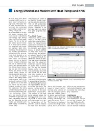
Light strip 1 Light strip 2 Light strip 3<br />
~ 26 % ~ 48 % ~ 70 %<br />
Receiver Receiver Receiver<br />
500 lux required light intensity<br />
Necessary<br />
artificial light<br />
Existing daylight<br />
Goal: Brightness control optimised for all areas of the room<br />
3 Principle<br />
Closed-loop and open-loop lighting control systems are based on the modulation of the<br />
lighting level inside the room by the measurement of either the level of external light<br />
(independent variable) or the measurement and feedback of the level of internal light<br />
(dependent variable) which contains a variable proportion of external light. In both<br />
variants, the primary goal is to maintain a required level of internal light as constant as<br />
possible. In general, it is a feature of a distributed system such as <strong>KNX</strong> that the individual<br />
tasks in the closed-loop or open-loop control systems are distributed among different<br />
devices: sensors, actuators and controller modules. This has both benefits and<br />
disadvantages as outlined below in detail.<br />
4 Constant <strong>Lighting</strong> <strong>Control</strong><br />
A closed-loop control circuit is used for constant lighting control. The required level of<br />
brightness in the room or the level of lighting at the desk is measured as a controlled<br />
variable together with the interference from the external light and then fed back to the<br />
actuators in the appropriate manner.<br />
<strong>Control</strong>ling system<br />
<strong>Control</strong>led system<br />
Z<br />
W <strong>Control</strong>ler Y Actuator Contr. variable X<br />
X+Z<br />
- +<br />
Measuring device<br />
Brightness<br />
sensor<br />
W ... Reference variable (e.g. brightness, setpoint)<br />
Y ... <strong>Control</strong> value (dimming value 1-100%)<br />
Z ... Interference (level of external light)<br />
X ... Actual value (lux value at workstation)<br />
Figure 1: Constant lighting control<br />
Home and Building Management Systems<br />
<strong>KNX</strong> Association<br />
<strong>Lighting</strong> <strong>Control</strong> <strong>Lighting</strong> <strong>Control</strong>_E0310a 5/34
<strong>KNX</strong> ADVANCED COURSE<br />
4.1 Constant <strong>Lighting</strong> <strong>Control</strong>: Areas of Application, Objective<br />
This type of control system is mainly used in commercial installations where it is important<br />
to adhere to certain regulations such as those governing the workplace but not to make<br />
more light available than necessary. The aim is to create optimum working conditions<br />
while at the same time saving costs. The user should also be offered an optimum level of<br />
convenience and the internal room controller should operate independently of other<br />
parameters which cannot be detected here.<br />
4.2 Types of Closed-loop <strong>Control</strong><br />
A distinction is made between Closed-loop <strong>Control</strong> and the so-called Integral Reset. In the<br />
first control system, the control value is directly influenced by the setpoint/actual value<br />
differential. For example, an absolute dimming value is sent to the actuators via a<br />
feedback function (dependent on the measured lighting level but with a variable proportion<br />
of external light). The negative feedback of the control value on the comparison point of<br />
the closed-loop control circuit as well as the system deviation with forward gain are<br />
governed by one function. The greater the influence on the control value, the higher the<br />
failure rate of the system deviation.<br />
Integral Reset on the other hand operates according to the two-step principle. The control<br />
value for the brightness level of the actuators is modified indirectly or gradually, namely<br />
via relative dimming telegrams. After this type of dimming process, the lighting sensor<br />
measures the surface again that is to be constantly illuminated, compares it with the<br />
setpoint and then decides again in which direction further dimming should take place. The<br />
respective level of change carried out to the control value remains constant at each new<br />
activation. It is not dependent on the degree of system deviation<br />
Two-step control is actually not a proper closed-loop control system as it rarely achieves<br />
the required setpoint. This type of control only has an opening/closing point instead of<br />
continuous dimming processes which must be provided with a sufficiently large hysteresis<br />
to prevent the triggering of continuous opening/closing operations. This type of lighting<br />
control is described in more detail under the section “Brightness control”.<br />
Home and Building Management Systems<br />
<strong>KNX</strong> Association<br />
<strong>Lighting</strong> <strong>Control</strong> <strong>Lighting</strong> <strong>Control</strong>_E0310a 6/34
<strong>KNX</strong> ADVANCED COURSE<br />
4.3 Usable Bus Devices<br />
Since we are specifically discussing the maintenance of a constant level of illuminance,<br />
only actuators that allow variable illumination are permitted. They must therefore be<br />
dimming actuators. A required characteristic of <strong>KNX</strong> dimming actuators is that it must be<br />
possible to control them in three different ways: switching, relative dimming via 4 bit<br />
information and absolute dimming via 8 bit information. Sensors for this control system<br />
must first only be able to measure the actual brightness value with sufficient accuracy and<br />
frequency without supplying upper limit values in the required band width. As regards<br />
accuracy, the sensor that offers a logarithmic resolution is the most beneficial. This means<br />
that is must be able to carry out more precise measurements in the lower range than in<br />
the upper range as the human eye reacts less to absolutely identical changes with an<br />
increasing level of brightness. When judging whether a closed-loop control system is<br />
better or worse than another type of system, only a relative estimation of accuracy is<br />
necessary. If an adjustment to 1500 lux is required for example and the maximum system<br />
deviation is +/- 150 lux i.e. 10 %, this is equivalent to an adjustment to 500 lux at an<br />
absolute value of +/- 50 lux.<br />
The third component of this control system is a controller which takes over the actual<br />
control task. It receives the measured brightness value as an input and compares it with<br />
the setpoint which is available e.g. as a parameter (fixed value) or as an object value (can<br />
be modified at any time via the bus). From these two values, it can determine the output<br />
(control value) according to the implemented algorithm (control function) and send it to the<br />
actuator.<br />
In practice, particularly due to cost and space restrictions, the manufacturers of these<br />
types of components decide to integrate the controllers into the sensors or even to build<br />
the entire controller and sensor component into the actuator.<br />
4.4 Characteristics of Sensors and Actuators<br />
4.4.1 Sensors<br />
As stated above, brightness sensors that are used for lighting control should have a<br />
measured-value resolution available that is adapted to the setpoint. A system deviation<br />
below approx. +/- 15% is still not noticed by the user. The accuracy or tolerance of the<br />
measuring sensor as well as the losses caused by A/D conversion in the <strong>KNX</strong> sensor<br />
must be added together i.e. lie below this figure. Example: The setpoint is 600 lux; the<br />
tolerance is therefore +/- 90 lux. The individual possible measured values must thus be<br />
separated by less than 90 lux. The fact that indirect measurements are always carried out<br />
causes a problem. It is not the luminous flux of the lamp that is measured, but the<br />
reflected light output from the reflected surface. It is easy to imagine that a dark surface is<br />
less reflective than e.g. a white desk. The structure of the surface can also influence the<br />
recording of the measured value. In principle, it can be said that the light is scattered to a<br />
greater or lesser degree and the measured value of the sensor is lower than for direct<br />
measurement. Due to the varying reflectance factors, sensor heads must have a variable<br />
gain available which can be adapted to the respective requirements. This gain must be<br />
carried out in front of the A/D converter as otherwise the resolution is reduced by the gain<br />
factor and the control precision decreases. The measured value can thus be adapted via<br />
this gain factor under the named requirements in the course of a calibration procedure so<br />
Home and Building Management Systems<br />
<strong>KNX</strong> Association<br />
<strong>Lighting</strong> <strong>Control</strong> <strong>Lighting</strong> <strong>Control</strong>_E0310a 7/34
<strong>KNX</strong> ADVANCED COURSE<br />
that it can be used simultaneously as a lux value that can be displayed. The correct<br />
measured brightness value is generally sent cyclically by the sensor. The value differential<br />
and time interval that are used for sending can be set in a wide range in most cases for<br />
the available devices. In addition to the cyclical sending variant, it is also possible to react<br />
quicker with event control if the measured brightness value changes significantly.<br />
4.4.2 Closed-loop <strong>Control</strong>ler types<br />
The example outlined above now requires a closed-loop controller, which uses the<br />
setpoint/actual value comparison to determine how the control value must be modified in<br />
order to return to the desired equilibrium of setpoint = actual value. The details of this<br />
control technology will not be discussed here, only the feasible alternatives.<br />
This so-called closed-loop procedure can contain proportional, integral and differential<br />
feedback components. This means:<br />
proportional: a direct control output ‘y’ is calculated for the dimming actuator from the<br />
setpoint/actual value differential ‘x’ via simple, linear conversion function according to<br />
the function y = a . x<br />
integral: the control output is integrated with a specific rate i.e. it is zero at the<br />
beginning and reaches the calculated value y = a . x . t only after a certain period<br />
differential: the control output is determined from the rate of change of the system<br />
deviation y = x/t<br />
Only the P controller can be used directly by these basic functions of control technology.<br />
The use of a P controller however leads to a systematic deviation which cannot be<br />
reduced due to the requirement to avoid oscillations. Only an integrating controller would<br />
function better in our case as it finds a stable state after a certain period in which it<br />
remains while there are no changes to the external light intensity. The D controller reacts<br />
very quickly if there is a substantial change in the parameters. The response to this<br />
change dies down again after a certain period.<br />
Apart from the continuous control of the setpoint, it is now important for an optimum<br />
lighting control system that the change in the brightness level runs almost imperceptibly<br />
for the user. Extreme external variations in the lighting should also not influence the<br />
control output at such a rate that it causes an imbalance. P and D controllers are therefore<br />
rarely used for lighting control systems. Only integral action control is in practice sufficient<br />
to fulfil the requirements of the user.<br />
In most cases, the integral action control has an indirect rather than direct influence on the<br />
control output. We are then using the “integral reset” procedure.<br />
In practice, this means that the closed-loop controller modifies the control output stepwise<br />
and indeed always by the same amount per temporal unit, which is a modification of a true<br />
integral controller, since the steps are always of the same size. In the <strong>KNX</strong> system, 4 bit<br />
dimming telegrams (DPT 3.007) are predestined for this as they transfer these constant<br />
changes in value that do not contain any different values (apart from the sign) as is the<br />
case with an absolute 8 bit control output. Any considerable variations in the parameters<br />
always cause the same rate of change. Since the change in brightness should take place<br />
gradually, only the step widths 1/64 (1.6%) or 1/32 (3.2%) are recommended for DPT<br />
3.007. 4 bit dimming telegrams are sent continually at a certain rate, provided that the<br />
actual value does not meet the setpoint within the hysteresis. If the hysteresis range is<br />
reached, the controller stops.<br />
Home and Building Management Systems<br />
<strong>KNX</strong> Association<br />
<strong>Lighting</strong> <strong>Control</strong> <strong>Lighting</strong> <strong>Control</strong>_E0310a 8/34
<strong>KNX</strong> ADVANCED COURSE<br />
Figure 2: Example of a closed-loop controller with an integrated sensor<br />
In the objects of figure 1, it is possible to detect that further possibilities can be<br />
implemented apart from the actual dimming function (= control value). These options<br />
enable a very convenient use of the control system:<br />
Setpoint adjustment via absolute (direct) value control<br />
Master /slave function for additional lighting circuits<br />
Toggling between manual and automatic mode via all operator functions which the<br />
dimming actuator is aware of (i.e. switching, dimming and value setting)<br />
The previous statements about the procedure used by DPT 3.007 2 do not however mean<br />
that an integral reset can only be carried out with DPT 3.007 only. This procedure can<br />
also be implemented with DPT 5.001 telegrams. The controller thus starts with an initial<br />
value, mainly 0 or 255, and sends further telegrams as with DPT 3..07, which now contain<br />
8 bit values that are reduced or increased by a constant value compared to the previous<br />
value. Some devices also manage to retrieve the present dimming value of the actuator to<br />
be controlled and start from this one instead 0 or 100%. The benefit of this procedure<br />
compared to DPT 3.007 appears to be that the resolution increases until it reaches steps<br />
of 0.4%. This means it is possible to make even finer adjustments in the dimming process.<br />
The bus load should however be taken into account since it rises when smaller changes in<br />
the value are carried out.<br />
The device shown in figure 2 is an example for 8-bit closed loop control.<br />
4.4.3 Actuators<br />
No particular requirements are placed on the dimming actuators initially as only the 4 bit<br />
or 8 bit object is required for integral reset. It is however important to be able to select<br />
whether this type of actuator should switch off or not when dimming down continually. It is<br />
likewise the case with the opposite process. If the closed-loop control is switched on, it<br />
should be possible to switch on using 4 bit dimming commands. The timing/dimming curve<br />
must be active for both 8 bit value dimming and the 4 bit dimming process as the actuator<br />
otherwise dims brighter or darker step by step. The <strong>KNX</strong> dimmers and dimming actuators<br />
that are currently available on the market fulfil almost all these conditions which is not<br />
always the case with older devices. To optimise the dimming process, the dimming speed<br />
Home and Building Management Systems<br />
<strong>KNX</strong> Association<br />
<strong>Lighting</strong> <strong>Control</strong> <strong>Lighting</strong> <strong>Control</strong>_E0310a 9/34
<strong>KNX</strong> ADVANCED COURSE<br />
of the actuator and dimming step width and send interval of the controller should match<br />
precisely:<br />
If e.g. 1/64 dimming telegrams are sent every 2 seconds, the dimmer must be set so that<br />
it makes a full cycle of 0 – 100% in 128 sec and no faster.<br />
If it should also be possible to operate the dimmer manually, a shorter dimming period is<br />
of course required. Differences can therefore be found in this regard between the<br />
available devices as not all of them offer this possibility (see the note in the next section).<br />
4.5 Parameterisation Notes, Flags, Possible Errors, Bus Load etc.<br />
The previously named condition (dimming period of 128 sec) is optimised for the control<br />
system but not for manual operation. A compromise must often be made: the actuator<br />
dims at a slightly slower rate e.g. in 8 sec and the controller transmits at a slightly faster<br />
rate to avoid stepwise brightness processes. This increases the bus load however.<br />
Alternatively 1/32 is used as a step width instead of 1/64 to reduce the bus load again.<br />
This produces a further problem in the case of very bright luminaires (over-dimensioned or<br />
still new). The changes in brightness can already be greater than the set hysteresis after a<br />
single step of 1/32. This results in continuous fluctuations as the luminaire continually<br />
exceeds or falls below the target value.<br />
500 lx<br />
Hysteresis<br />
Interior<br />
lighting<br />
External brightness<br />
Figure 3: Mismatch of dimming step width and hysteresis<br />
The extension of the hysteresis or reduction of the dimming step width can provide some<br />
help:<br />
500 lx<br />
Hysteresis<br />
Interior<br />
lighting<br />
External brightness<br />
Figure 4: Correct ratio of dimming step width and hysteresis<br />
Home and Building Management Systems<br />
<strong>KNX</strong> Association<br />
<strong>Lighting</strong> <strong>Control</strong> <strong>Lighting</strong> <strong>Control</strong>_E0310a 10/34
<strong>KNX</strong> ADVANCED COURSE<br />
A better option is the use of dimming actuators with two time bases. This option has<br />
become more common since dimming actuators based on BCU2 have come on to the<br />
market. It is then really possible to implement a manual and automatic function: manual<br />
operation = short dimming time base, automatic = long dimming time base.<br />
Figure 5: Objects of a switch/dim actuator with a dual time base<br />
Home and Building Management Systems<br />
<strong>KNX</strong> Association<br />
<strong>Lighting</strong> <strong>Control</strong> <strong>Lighting</strong> <strong>Control</strong>_E0310a 11/34
<strong>KNX</strong> ADVANCED COURSE<br />
4.6 Parameterisation Example<br />
4.6.1 Functions<br />
We use 3 <strong>KNX</strong> components in this layout for a complete control system: a sensor with an<br />
integrated controller (type = integral reset by 8 bit), a dimming actuator with a dual<br />
dimming time base and a 3-fold push button with text display that enables the following<br />
functions.<br />
Function<br />
Effect<br />
Switch light manually (basic)<br />
Switches actuator on/off, interrupts the CLL*)<br />
control<br />
Dim light manually (basic)<br />
Dims the actuator, interrupts the CLL control<br />
Switch automatic CLL control on/off (basic)<br />
Starts the CLL control with the parameterised set<br />
point or stops it<br />
Set value manually for lighting<br />
(continuously) (optional)<br />
Sets the brightness value at the actuator between<br />
0 and 100%, interrupts the CLL control<br />
Presence (optional)<br />
CLL control triggered by a movement / presence<br />
detector; or simpler, just by switch<br />
Setpoint shift (optional)<br />
Variable LUX value setpoint control<br />
Calibration<br />
Only for commissioning (or for advanced users to<br />
recalibrate later)<br />
*) CLL: closed loop lighting<br />
The usual range in which setpoint values can fluctuate is between 250 lux (lighting level<br />
for less demanding activities) and 1500 lux (level for light-intensive laboratory<br />
workstations where optical equipment is used such as lenses, microscopes etc.). The<br />
sensor must maintain a system deviation of max. +/-15% throughout the range.<br />
Two further functions/group addresses are required to calibrate the arrangement after the<br />
installation:<br />
measured lux value (to compare with the external lux meter)<br />
calibration trigger<br />
The brightness sensor/controller already mentioned above also enables calibration to be<br />
carried out. The address ‘measured lux value’ is not really always necessary but strongly<br />
recommended to be used in order to have an indication about how far the real measured<br />
value and that one of the <strong>KNX</strong> sensor differ before the calibration is started. The<br />
calibration process will calculate just a (for the user not accessible) gain factor between<br />
Home and Building Management Systems<br />
<strong>KNX</strong> Association<br />
<strong>Lighting</strong> <strong>Control</strong> <strong>Lighting</strong> <strong>Control</strong>_E0310a 12/34
<strong>KNX</strong> ADVANCED COURSE<br />
the physically measured light level and the either parameterized or via object adjusted<br />
setpoint.<br />
4.6.2 Example<br />
The sensor would – after the initial full application download – send a value of 200. But a<br />
Luxmeter would see 500 Lux. The setpoint of the sensor is also 500 Lux. (It has to be –<br />
otherwise the calibration would be faulty). So after the calibration trigger telegram has<br />
been sent, the new measured value would be returned with “500”.<br />
Only a connection between the controller and the actuator is now missing:<br />
Automatic value control (Master value)<br />
4.6.3 Parameters<br />
Figure 6: <strong>Control</strong> parameters of the closed loop controller<br />
Explanations:<br />
Operating mode: “Constant light level control” is used for continuous dimming<br />
Number of slaves: Only 1 master channel required, so no slaves = 0<br />
Send meas. brightn.: (optional) the sensor value can be displayed and monitored<br />
Min. variation…: “15 Lux” means, with deviations of equal or more than 15 Lux a new<br />
value will be sent.<br />
Setpoint value: “Parameter” or “Comm. Object”; the latter one allows flexible setting<br />
of the setpoint<br />
Max. var. from setp.: Half of the double sided hysteresis (varies from 15 to 60 Lux)<br />
Max. step size …: varies from 0.5 up to 3%; = difference between 2 master value<br />
telegrams;<br />
Transmit next…: 2 sec; i.e., together with “max. step” 0-100% = 120 sec.<br />
Home and Building Management Systems<br />
<strong>KNX</strong> Association<br />
<strong>Lighting</strong> <strong>Control</strong> <strong>Lighting</strong> <strong>Control</strong>_E0310a 13/34
<strong>KNX</strong> ADVANCED COURSE<br />
Start and finish…:<br />
The controller will firstly read the value status, then calculate the<br />
next telegram to be sent, and also stop with a 0% value telegram<br />
Figure 7: Parameter (extract) of the switch/dim actuator<br />
This setting enables a manually operated dimming speed of 5 sec per 100%.<br />
The factor for the “dimming time 2” (plus its base timer “seconds”) rules an automatic<br />
dimming time of 120 sec.<br />
This time equals exactly the setting of the master channel of the brightness controller.<br />
Home and Building Management Systems<br />
<strong>KNX</strong> Association<br />
<strong>Lighting</strong> <strong>Control</strong> <strong>Lighting</strong> <strong>Control</strong>_E0310a 14/34
<strong>KNX</strong> ADVANCED COURSE<br />
4.6.4 Group Addresses<br />
To summarise, all the group addresses are listed here again:<br />
Figure 8: Group address configuration in a convenient constant lighting control system<br />
4.6.5 Linking of Sensor and Actuator Objects, Operation<br />
In our example a push button with text display (LCD) is used to provide proper labelling of<br />
the control functions and the (optional) display of values.<br />
Very often, however, customers don’t want to spend so much money, so they only use a<br />
local pushbutton for simple switching and dimming control as manual override, and the<br />
automatic activation will be done e.g. by a central scheduler, or by the twilight sensor on a<br />
weather central.<br />
Figure 9: Group address links between the 3 <strong>KNX</strong> devices<br />
Home and Building Management Systems<br />
<strong>KNX</strong> Association<br />
<strong>Lighting</strong> <strong>Control</strong> <strong>Lighting</strong> <strong>Control</strong>_E0310a 15/34
<strong>KNX</strong> ADVANCED COURSE<br />
4.6.6 Additional Notes<br />
In general, the actuator is also addressed via central functions (see above) which switch<br />
the lights on/off directly or also activate/deactivate the control for example via a time<br />
switch. This must also be taken into account in the controller. A direct central switching<br />
operation must also switch off the controller with positive drive. These addresses must<br />
therefore also be linked to the disable objects of the controller; otherwise the controller will<br />
always act against this external input and try to dim up the lights again.<br />
4.7 Installation Notes<br />
Many factors are decisive for the optimum installation of a brightness control system.<br />
Some are listed here:<br />
4.7.1 Alignment of the Measuring Sensor<br />
The surface that is to be measured should be as undisturbed as possible i.e. should never<br />
indicate different surface characteristics. External light should not directly penetrate the<br />
receiving lens if possible, likewise artificial light.<br />
Building ceiling<br />
Correct Incorrect<br />
Lamp<br />
Suspended<br />
ceiling<br />
Receiver<br />
Mounting height 2.5 - 6 m<br />
Light cone<br />
Correct<br />
Incorrect<br />
0<br />
4<br />
w<br />
A<br />
n<br />
A<br />
_<br />
5<br />
9<br />
1<br />
Calibration required<br />
Measuring sensor +/-15%<br />
Daylight<br />
Figure 10: Optimum position of the measuring sensor (graphics do not resemble the sensor<br />
exactly)<br />
4.7.2 Several Light Strips with a Varying Proportion of External Light:<br />
In this case, which rarely occurs, a single brightness sensor is only sufficient if it is<br />
possible to generate different control values for the individual actuator channels. If you do<br />
not have a controller that can do this, a separate sensor must be installed for each light<br />
strip. As mutual influences (mostly unwanted) can arise, a partitioning of the sensors must<br />
take place and the overlapping of the lighting surfaces underneath the individual strips<br />
must be minimised. It can, however, invariably lead to oscillation processes or at least an<br />
unexpected distribution of brightness (although the measured values of the sensors are<br />
correct). The technically better solution nowadays is to only control one strip (whereby it is<br />
not possible to simply select any strip but the strip which is installed at the window side,<br />
which reacts the most sensitively to daylight changes). The other lighting strips are simply<br />
Home and Building Management Systems<br />
<strong>KNX</strong> Association<br />
<strong>Lighting</strong> <strong>Control</strong> <strong>Lighting</strong> <strong>Control</strong>_E0310a 16/34
<strong>KNX</strong> ADVANCED COURSE<br />
interfaced via a control function e.g. offset adjustment is a so-called master/slave circuit<br />
(see the explanations in section 5).<br />
Light strip 1 Light strip 2 Light strip 3<br />
~ 26 % ~ 48 % ~ 70 %<br />
Receiver<br />
Slave 2 Slave 1<br />
Master<br />
500 lx required illuminance<br />
Necessary<br />
artificial light<br />
Existing<br />
daylight<br />
Figure 11: Brightness control of a light strip, combined with offset control for the other light<br />
strips<br />
4.7.3 Fundamental Mismatch<br />
A mismatch always occurs in this system. This is based on the one hand on the different<br />
lighting spectrum of natural light and artificial light and on the other hand, on the different<br />
angle of illumination. The more external light comes in, the greater the measuring error,<br />
because the natural light also is picked up by the sensor rod directly instead of only from<br />
the controlled surface by reflection. A curve of the controlled variable is produced<br />
dependent on the external brightness which reaches its minimum in a ratio of 50:50<br />
between the proportion of external and internal light. The system must always be<br />
balanced under these lighting conditions.<br />
Ф internal<br />
[lx]<br />
Optimum adjustment value<br />
Actual<br />
value<br />
500<br />
Setpoint<br />
250<br />
Actual<br />
internal value<br />
Proportion of<br />
artificial light<br />
Proportion of<br />
external light<br />
Ф external<br />
[lx]<br />
Figure 12: Behaviour of the actual value dependent on the level of external light<br />
Home and Building Management Systems<br />
<strong>KNX</strong> Association<br />
<strong>Lighting</strong> <strong>Control</strong> <strong>Lighting</strong> <strong>Control</strong>_E0310a 17/34
<strong>KNX</strong> ADVANCED COURSE<br />
5 Brightness <strong>Control</strong><br />
5.1 Areas of Application, Objective<br />
In contrast to lighting control in which you wish to achieve individual and optimum levels of<br />
light intensity as mentioned above, brightness control is mostly considered with regard to<br />
minimising installation costs without fully losing sight of the goal of reducing energy costs.<br />
It is however agreed between the planner and user that significant deviations from the<br />
setpoint/actual value can occur in the control system. This is particularly the case when<br />
only switchable lamps are integrated in the control system.<br />
Figure 13: Principle of brightness control<br />
5.2 Types of Open-loop <strong>Lighting</strong> <strong>Control</strong><br />
For brightness control, a distinction is made between continuous control and two-step<br />
control. A sensor measures an external brightness value which is independent of the<br />
internal illuminance that is to be set. Starting from this measured value, the internal control<br />
value is determined at first via any calculation function which the room illuminance uses to<br />
reach the required setpoint. Technically this is an open control loop. The feedback loop is<br />
missing. This has both advantages and disadvantages. It is beneficial that this type of<br />
lighting control can never oscillate since the feedback loop has been omitted as<br />
mentioned. Starting with the measured value of a single sensor, many different control<br />
curves can be differentiated. The disadvantage is that a very extensive adjustment must<br />
be carried out for continuous control which takes at least one day.<br />
5.2.1 Continuous <strong>Control</strong><br />
Continuous control – like the closed-loop control above – requires dimmers or dimming<br />
actuators which can be infinitely adjusted. As an automatic adjustment of the control value<br />
cannot take place (due to the missing feedback loop), this must be carried out by selecting<br />
a control function. In the simplest case, this can be a straight line determined by two pairs<br />
of values: a) maximum external brightness above which there should be 100% interior<br />
Home and Building Management Systems<br />
<strong>KNX</strong> Association<br />
<strong>Lighting</strong> <strong>Control</strong> <strong>Lighting</strong> <strong>Control</strong>_E0310a 18/34
<strong>KNX</strong> ADVANCED COURSE<br />
lighting and b) minimum brightness level above which the light should be switched off.<br />
Moreover, the control module must be in a position to carry out a hysteresis in order to<br />
ease control in the extreme range between switched on and switched off.<br />
Figure 14: Characteristic curve for brightness control – a hysteresis is advisable<br />
5.2.2 Two-step <strong>Control</strong><br />
The characteristic curve described in the previous section is further simplified if only two<br />
states are possible for the controlled lamps: ON or OFF.<br />
Switching value<br />
1<br />
Switch Off point<br />
Hysteresis<br />
0<br />
0<br />
Switch On point<br />
2000 4000 6000 [ lux ]<br />
Measured value of brightness sensor<br />
Figure 15: Principle of two step control<br />
Home and Building Management Systems<br />
<strong>KNX</strong> Association<br />
<strong>Lighting</strong> <strong>Control</strong> <strong>Lighting</strong> <strong>Control</strong>_E0310a 19/34
<strong>KNX</strong> ADVANCED COURSE<br />
5.3 Usable Bus Devices<br />
5.3.1 General<br />
A separation between the sensor and actuator technology is advisable. The control<br />
system takes over the evaluation of the sensors (including push buttons) and triggers the<br />
actuators.<br />
5.3.2 Sensors<br />
Almost all the devices that can evaluate external inputs can be considered as sensors for<br />
brightness control. This includes the simple two-step control via a binary input that is<br />
coupled with a floating contact of a light sensor. The disadvantage in this case is that the<br />
switching points and hysteresis cannot be influenced via the <strong>KNX</strong> by telegram or at least<br />
by downloadable device parameters.<br />
Analogue inputs with <strong>KNX</strong> capability which supply a measured value in DPT 9.004 format<br />
in lux units are better in this case. The sensors that offer an almost logarithmic resolution<br />
of the measured signal are beneficial and of course completely cover the required area. If<br />
this is not the case, the measured-value resolution – as mentioned above – should be<br />
sufficiently precise for light control values approx. >50% so that visible fluctuations in the<br />
brightness level do not occur in the area in which the artificial light is predominant. As we<br />
saw above with closed-loop control, the maximum step width may not be higher than a<br />
3.2% dimming value differential. This characteristic must of course also apply here. This<br />
means that we should have at least 50/3.2 = 16 steps in the range 50%-100% for the<br />
dimming setpoint. You can now easily specify whether a sensor is sufficient in practice or<br />
is not precise enough.<br />
Example: A sensor records 1000 lux of external brightness, the dimming level lies at 50%.<br />
The resolution of the sensor dimming level lies at 50%. The resolution of the sensor must<br />
be at least 1000 / 16 = 6.25 lux. A small query regarding the theory – if this sensor with a<br />
resolution of 62.5 lux already had a dimming level of 50% at an external brightness of 500<br />
lux – is it suitable or not?<br />
5.3.3 Actuators<br />
As stated above under 3.4.3, there is no limit applicable here. All the actuators designed<br />
for normal dimming can be used. All the binary outputs can be used again for two-step<br />
control.<br />
5.3.4 <strong>Control</strong>lers<br />
The brightness control system covers several different control curves. It is therefore a<br />
good idea to implement the functions ‘measure external light level’ and ‘trigger actuators’<br />
in a special module which doesn’t have to be directly linked with the light sensor via cable.<br />
In this case, it is possible to concentrate on the optimum position for placing the<br />
measuring sensor, as the measuring signal is already formatted as a DPT 9.004 telegram<br />
in the <strong>KNX</strong>-coupled sensor and then routed through the <strong>KNX</strong> network as appropriate. A<br />
controller module is then located in a distribution board which derives a range of different<br />
control curves from the incoming measured value. It is of course always possible to<br />
interface another system via a gateway in which DDC functions are also available. This is<br />
Home and Building Management Systems<br />
<strong>KNX</strong> Association<br />
<strong>Lighting</strong> <strong>Control</strong> <strong>Lighting</strong> <strong>Control</strong>_E0310a 20/34
<strong>KNX</strong> ADVANCED COURSE<br />
not a <strong>KNX</strong> lighting controller but the conversion is carried out externally in the DDC which<br />
then sends new dimming control values in response via the gateway to a new measured<br />
value of the lighting sensor. (E.g. gateways to Profibus).<br />
Figure 16: Conversion of the measured value of the light sensor in different control curves<br />
5.4 Parameterisation Notes, Flags, Bus Load etc.<br />
Having already discussed all the important characteristics of the actuators and sensors<br />
involved in the ‘<strong>Lighting</strong> control’ section, we can now briefly summarise here: statements<br />
regarding flags (readability of status objects) and inclusion of manual operation in the<br />
automatic system (time-limited interruption of control) also apply here of course. If the<br />
lighting should also be switched/dimmed manually via local push buttons or set directly to<br />
values, the control system must also be aware of the addresses, otherwise manual<br />
operation leads inevitably to an immediate correction by the automatic system.<br />
As we no longer have a control loop, it is also possible under certain conditions to<br />
implement minimum and maximum limit values for the dimming control value within which<br />
the control system operates. Otherwise it is switched off (manual operation). To prevent<br />
frequent switching in the two limit ranges, minimum ON and/or maximum OFF times can<br />
be requested as well as an ON/OFF hysteresis. The module that can fulfil these additional<br />
requirements is of course preferable to those with pure control curve functions.<br />
The bus load also plays a role here: it is not merely a question of value dimming but also<br />
whether and how the cyclical and/or event–controlled sending of the lighting measured<br />
value should be set best. It should first be considered that each new brightness value from<br />
the sensor results in the same number of value dimming telegrams as active control<br />
curves.<br />
Home and Building Management Systems<br />
<strong>KNX</strong> Association<br />
<strong>Lighting</strong> <strong>Control</strong> <strong>Lighting</strong> <strong>Control</strong>_E0310a 21/34
<strong>KNX</strong> ADVANCED COURSE<br />
5.5 Parameterisation Example<br />
Figure 17: Links between switch sensors, actuators and the control unit, consisting of the<br />
brightness sensor and control module<br />
In the above diagram, it can be seen that it is not only the external brightness and<br />
dimming control values (‘set value’) from the controller to the dimming actuators that are<br />
important, but also the ON/OFF lighting command, the optional 4 bit dimming and the 8 bit<br />
value setting of the manual push button. The application shown is – as in the closed-loop<br />
control described in paragraph 3 – able to convert increases and decreases in the<br />
dimming value into an adjustment of the control curves. The logic operation of the status<br />
value is required however as this determines the parallel displacement of the curve. What<br />
is still missing in this diagram would be a true automatic ON/OFF function which is<br />
controlled via a time switch. This <strong>KNX</strong> clock would also use the group addresses<br />
‘Enable/disable control’ and ‘<strong>Control</strong> ON/OFF’.<br />
Figure 18: Parameter of 2 different brightness sensors: linear vs. logarithmic value<br />
calculation<br />
The setting for “Sending on change” should not be too precise. The 1 st sensor allows 5%<br />
changes, always related to the last sent value. Such a value calculation goes along with<br />
Home and Building Management Systems<br />
<strong>KNX</strong> Association<br />
<strong>Lighting</strong> <strong>Control</strong> <strong>Lighting</strong> <strong>Control</strong>_E0310a 22/34
<strong>KNX</strong> ADVANCED COURSE<br />
the logarithmic impression of brightness by the human eye and is much better than a<br />
linear output (equidistant values) of sensor 2. Still an option of limiting the amount of bus<br />
telegrams per time unit should be available (not visible in this example here).<br />
Regarding sensor 2 (Figure 18 lower image): If a measured value interval of 64 lux is still<br />
sufficient in the lower range (see 2 nd example above), then the factor should be 8 instead<br />
of 4 as shown. During cyclical repetition of the measured value – if parameterised –values<br />
like those shown above are completely unsuitable: assuming that 10 control curves are<br />
implemented, up to 11 telegrams in total can occur every 650 msec. The bus load would<br />
then already be over 30%. The aim should however be to remain below 2%. Assuming<br />
that a maximum of 45 telegrams can be sent on the line on average, then 2% would<br />
correspond to 0.9 telegrams / sec. In the case of the aforementioned 11 telegrams per<br />
measured value, this means that a measured value may be sent approx. every 12<br />
seconds. This timing resolution is probably quick enough, primarily, because the controller<br />
calculates the new control values in proportion and does not always send constant<br />
dimming steps as in integral-action closed-loop control. The correct parameter<br />
combination for sending the cyclical measured values is then:<br />
Base = 130 ms; Factor = 12 sec / 130 ms = 92<br />
Dimming<br />
value<br />
250 0<br />
Measured<br />
value<br />
250<br />
250 500<br />
200 1000<br />
150 2000<br />
125 3000<br />
75 4500<br />
25 8000<br />
25<br />
1000<br />
8000<br />
Figure 19: Value table for lighting control: a monotone falling curve is important<br />
The table shown in the diagram figure 19 can be specified arbitrarily at first. An<br />
approximation of a comparable constant lighting control system can mainly be achieved<br />
over 3 points. The two values of complete darkness or the level of daylight that is<br />
sufficient to light up a room or part of it without artificial light can be quickly determined<br />
using a lux meter. The value pair that starts the proportional range should be verified next:<br />
in our example this is 500 lux / control value 250 (98%). If there are still considerable<br />
deviations in the intermediate lux values, it is possible to ‘recalibrate’ the particularly poor<br />
values a few days later.<br />
Home and Building Management Systems<br />
<strong>KNX</strong> Association<br />
<strong>Lighting</strong> <strong>Control</strong> <strong>Lighting</strong> <strong>Control</strong>_E0310a 23/34
<strong>KNX</strong> ADVANCED COURSE<br />
Figure 20: Parameter of a controller module<br />
It is then possible to check whether the curve-specific parameters of the controller (if<br />
available) fulfil the requirements of the customer. In our example, that would be<br />
the behaviour after bus voltage recovery; the open-loop control would be switched on<br />
here<br />
the minimum On time: if the external brightness should vary within the limit range so<br />
that the control value for the dimmer can fluctuate around the switching point, then the<br />
light remains switched on for at least 5 minutes<br />
the hysteresis limit values shown mean in our example that the light is only switched<br />
off at approx. 9000 lux (since there is then an underrange in the control value of 20)<br />
and switched on again at approx. 600 lux because the control value of 30 has been<br />
achieved again.<br />
Home and Building Management Systems<br />
<strong>KNX</strong> Association<br />
<strong>Lighting</strong> <strong>Control</strong> <strong>Lighting</strong> <strong>Control</strong>_E0310a 24/34
<strong>KNX</strong> ADVANCED COURSE<br />
5.6 Installation Notes<br />
The installation instructions for the open-loop lighting control system are reduced to notes<br />
about the installation of the sensor head:<br />
It must be directed outside or be installed outside the building.<br />
Its recording of the lighting level may not be influenced by seasonal variations such as<br />
leaves on the trees which stand between it and the sky or snow on the receiving lens.<br />
Its measurement may (for interior installation) also not be invalidated by the shutter.<br />
An installation behind the shutter or roller blind should be avoided where possible.<br />
The presence of shutters require a particular type of control: if proportionally-controlled<br />
shutters are present, the louvres of the shutters can be adjusted in parallel to the<br />
external brightness instead of the light.<br />
For an optimum adaptation of rooms that face different directions, it is advisable to use<br />
at least 2 differently positioned sensors: one in a south-east direction and another in a<br />
north-west direction. Large buildings may require even more sensors which should<br />
then be placed as perpendicular as possible to the respective façade and point<br />
upwards.<br />
6 Brightness <strong>Control</strong>, combined with Master/Slave <strong>Control</strong><br />
6.1 Objective<br />
With combined open-loop/closed-loop lighting control, you are in general pursuing the aim<br />
of saving costs without having to relinquish the benefits of a partially true closed-loop<br />
control system. These can be:<br />
a simple setting procedure<br />
optimum lighting conditions in at least one position in the room<br />
always the correct lighting level in the rooms even when combined with light direction<br />
and sun protection systems.<br />
6.2 Principle<br />
An internal sensor measures the lighting level of a surface that should be regulated – as in<br />
closed-loop control which was described in detail above. The measured values of the<br />
sensor are further processed in a control program resulting in a control value which is<br />
used to trigger the actuator that is responsible for the direct light strip. To eliminate the<br />
requirement for further sensors (and also their deviation), it transfers a full control curve<br />
via offset adjustment to all other curves. The required offset adjustment can be<br />
determined by 2-3 simple measurements: at an artificial lighting level of 25%, 50% and<br />
75%, the necessary offset of the controlled light strips is determined in comparison to the<br />
regulated strip to arrive at the required setpoint in lux. The largest recorded differential<br />
(upwards) per strip is then taken as this guarantees that the minimum lighting level never<br />
falls below the setpoint.<br />
Home and Building Management Systems<br />
<strong>KNX</strong> Association<br />
<strong>Lighting</strong> <strong>Control</strong> <strong>Lighting</strong> <strong>Control</strong>_E0310a 25/34
<strong>KNX</strong> ADVANCED COURSE<br />
6.3 Available Devices<br />
Since the offset adjustment is derived from the dimming value of a regulated dimming<br />
actuator, it would be possible for example to use the active status response (8 bit) of this<br />
type of dimming actuator and simply add it to the established offset in a function module<br />
or visualisation program. The newly specified control value would then be sent to the next<br />
controlled light strip via another group address.<br />
This procedure is however only advisable if the function module or visualisation program<br />
mentioned are also available or if there is a cost benefit in using them compared to a<br />
multi-layered lighting control system.<br />
In terms of device implementation, it is much simpler in any case to use multi-channel<br />
dimming actuators with an integrated sensor connection and controller application. It is<br />
also possible here to configure internal offset connections between the actuator channels<br />
so that fewer bus telegrams can be sent. This solution not only saves device addresses<br />
but also costs in general.<br />
6.4 Parameterisation Example<br />
In the following example, 3 light strips in one room should be regulated or controller with a<br />
single dimming actuator and only one light sensor. A time-limited manual operation<br />
(switching/dimming) of all 3 channels should be possible using a 4-fold push button. The<br />
fourth rocker should switch all 3 dimming channels back to automatic mode. A special<br />
‘cleaning light’ function should also be implemented: when a further<br />
1-fold push button is pressed, the light should be set to full brightness for 1 hour, the<br />
closed-loop/open-loop control should be deactivated and then everything should be<br />
switched off.<br />
Figure 21: Example of a complete 3-channel room control system with an automatic<br />
‘cleaning-light’ function: only 3 bus devices are required<br />
The following can also be detected in figure 21: emergency operating mode via local push<br />
buttons if the <strong>KNX</strong> should fail. In the case of the device shown, these push buttons have<br />
the additional function of triggering an automatic calibration of the respective sensor<br />
channel, if it acts as a master sensor in the closed-loop control.<br />
Home and Building Management Systems<br />
<strong>KNX</strong> Association<br />
<strong>Lighting</strong> <strong>Control</strong> <strong>Lighting</strong> <strong>Control</strong>_E0310a 26/34
<strong>KNX</strong> ADVANCED COURSE<br />
6.5 Installation and Solution Notes<br />
The most important factor in this option of open-loop/closed-loop lighting control is again<br />
the optimum selection of the installation place and the alignment of the sensors. The<br />
essential points have already been mentioned above but there is one additional factor: in<br />
combined closed-loop/open-loop control systems, it must be at least ensured, that in the<br />
situation of complete outdoor darkness all lights must be equally turned on to the same<br />
value (which should be ruled by the specification of the lighting system).<br />
A pure additive / subtractive offset control however means on the other hand, that the<br />
difference between the master and the slave will always be equal or less than the given<br />
value. The master dimming value can range between 0 and 100%, but the slave is limited<br />
to less than this due to the offset. That means: If e.g. slave 1 = master + 20% (master at<br />
the window side), and slave 2 = master + 40%, then both dependant rows can only be<br />
controlled in the range 20 – 100 resp. 40 – 100 %. If the master has reached 0%, again<br />
we have 2 options: the slaves shut off together with the master, then it is too dark there, or<br />
they stay on, then it is too bright. But at least at full darkness all rows are at or above the<br />
required lux value setpoint.<br />
If you look at the same situation, but now with the master in row 3 (darkest area), with a<br />
negative offset to the slaves, this means, at high outdoor light levels the dimming works<br />
fine, but the closer you come to full darkness, the more unequal the distribution of light<br />
would be. In the end row 1 reaches only 60%, row 2 goes to 80%. That this is not the<br />
optimum, is self explanatory.<br />
So the only conclusion can be: The sensor must be mounted in the window side row<br />
which then also must be controlled via closed loop control!<br />
Underneath a couple of illustrations to this problem:<br />
Figure 22: optimized situation, but only at one point !<br />
Home and Building Management Systems<br />
<strong>KNX</strong> Association<br />
<strong>Lighting</strong> <strong>Control</strong> <strong>Lighting</strong> <strong>Control</strong>_E0310a 27/34
<strong>KNX</strong> ADVANCED COURSE<br />
Figure 23: same as above, but at more external light – worst case situation !<br />
Figure 24: again same configuration, but at complete darkness – rows 2 and 3 “waste”<br />
energy!<br />
What is the conclusion of the notes mentioned above?<br />
If the offset of the slave is positive, then it will always be able to reach 100%, but cannot<br />
dim down to 0%, it will turn off with the master. If it is negative, it can switch off, but not<br />
reach 100% of dimming level.<br />
So there is never a 100% positive solution as with individual light sensors per each row of<br />
luminaries. However, using the configuration with the master at the window, and the<br />
slaves with positive offsets in the inner parts of the room, will provide a good compromise.<br />
The only slight disadvantage is, that the master will either have to turn off late (at more<br />
than 500 lx, which avoids the “gap”, but causes a much higher level at darkness, or there<br />
will be a situation, when the master turns off at 500 lx, where rows 2 and 3 still would need<br />
some light, but will switch of with the master.<br />
Home and Building Management Systems<br />
<strong>KNX</strong> Association<br />
<strong>Lighting</strong> <strong>Control</strong> <strong>Lighting</strong> <strong>Control</strong>_E0310a 28/34
<strong>KNX</strong> ADVANCED COURSE<br />
This is an issue, which can be cured when a light controller with a dynamic offset control<br />
is used (a multiplicative offset instead of a constant one). In this case the slave follows the<br />
master via a linear function like this: S = M x ( 1 + O ). O : = Offset [%]; S = Dimvalue [%]<br />
Slave; M = Dimvalue Master [%]. It can easily be seen that at M = 100% and O > 0 the<br />
value of S reaches 100%. At very small values of M, however, the absolute difference<br />
between S and M will come close to 0!<br />
Figure 25: Light controller with multiplicative offset<br />
7 Appendix Tasks<br />
7.1 Task 1: <strong>Lighting</strong> – <strong>Control</strong> dependent on External Light<br />
A room that is fitted with two light strips should receive a brightness control system. Up<br />
until now, the light strips have been switched and dimmed individually.<br />
The following are used:<br />
1 x 2-fold switch sensor, switching and dimming objects (4 bit)<br />
2 x switch/dim actuators, objects for switching, dimming, value setting and value status<br />
must be present.<br />
Group addresses for manual control:<br />
L1 Switch<br />
L2 Switch<br />
L1 Dim<br />
L2 Dim<br />
First put this simple series circuit into operation.<br />
The dimmable lighting in the room should now also be controlled by a brightness control<br />
module dependent on the external light.<br />
Home and Building Management Systems<br />
<strong>KNX</strong> Association<br />
<strong>Lighting</strong> <strong>Control</strong> <strong>Lighting</strong> <strong>Control</strong>_E0310a 29/34
<strong>KNX</strong> ADVANCED COURSE<br />
Figure 26: <strong>Lighting</strong> – <strong>Control</strong> dependent on external light<br />
Required devices:<br />
Brightness sensor e.g. Siemens 5WG1 254 3 AB 02 to record the brightness level<br />
(external light)<br />
Brightness control module e.g. Siemens 5WG1 342 1 AB 01<br />
2-fold push button<br />
Project design<br />
Define the following new group addresses<br />
• Brightness value of sensor (control module, sensor)<br />
• Calibration request (control module)<br />
• Dimming value for calibration (control module)<br />
• Brightness value for calibration (control module)<br />
• L1 Value set (--> switch/dim actuator + control module)<br />
• L2 Value set (--> switch/dim actuator + control module)<br />
• L1 Value status (--> switch/dim actuator + control module)<br />
• L2 Value status (--> switch/dim actuator + control module)<br />
• <strong>Control</strong> L1 enable / block (2-fold push button, automatic)<br />
• <strong>Control</strong> L2 enable / block (2-fold push button, automatic)<br />
Link the bus devices (<strong>Control</strong> 1 and 2 for L1 and L2).<br />
Check the read flag in the brightness sensor GE 253.<br />
Use the default parameter setting of the bus devices.<br />
Commissioning<br />
Put the brightness control module and brightness sensor into operation.<br />
You can now determine the control characteristics using the calibration objects.<br />
Home and Building Management Systems<br />
<strong>KNX</strong> Association<br />
<strong>Lighting</strong> <strong>Control</strong> <strong>Lighting</strong> <strong>Control</strong>_E0310a 30/34
<strong>KNX</strong> ADVANCED COURSE<br />
Establishing the control characteristics for L1 and L2<br />
Switch off the ambient lighting (artificial sun)<br />
Dim the lighting to the required brightness value. Note that the window luminaire (L1)<br />
requires a lower modulation (see also the sketch of the characteristic curve below).<br />
Mark the group address ‘Calibration request’ and select the item “read/write…”. In the<br />
telegram monitor then check if it is already online, otherwise connect to the bus first<br />
before the next step !<br />
Now be sure the selected group address still is selected; click on the “write” – button<br />
and enter the value ‘1’ for control characteristic 1 (L1), then click on “OK”.<br />
Change to the ‘Read value’ page and read out the status of the group address<br />
‘Dimming value for calibration’. Note the value.<br />
Now read out the status of the group address ‘Brightness value for calibration’. Also<br />
note this value.<br />
Repeat the process for control characteristic 2 (L2).<br />
An interpolation point of the two control characteristics is now known. Determine further<br />
points (at least 3) with different ambient light values (simulated external brightness<br />
values), whereby the last one should be carried out at the maximum brightness level of<br />
the ‘artificial sun’. Your determined values (hex code) could look as follows:<br />
Measured value of<br />
sensor<br />
Characteristic 1 Characteristic 2<br />
Dimming value L1<br />
Measured value<br />
of sensor<br />
Dimming value<br />
L2<br />
02A3 FF 02A3 B8<br />
0651 7A 0651 4F<br />
0F0A 37 0F0A 07<br />
2714 01 2714 00<br />
Converting the determined interpolation points of the characteristic curves<br />
As only decimal values can be entered in the parameters for the interpolation points of<br />
the characteristic curves, the determined hex values must be converted into decimal<br />
values. To do so, use the calculator (scientific) in the ‘Programs’ folder under<br />
‘Accessories’.<br />
Example:<br />
<strong>Control</strong> curve 1 <strong>Control</strong> curve 2<br />
Dimming value<br />
Dimming value<br />
255<br />
L1<br />
255<br />
184<br />
L2<br />
122<br />
55<br />
Measured<br />
value<br />
79<br />
7<br />
Measured<br />
value<br />
675<br />
1617<br />
3850<br />
10004<br />
675<br />
1617<br />
3850<br />
10004<br />
Home and Building Management Systems<br />
<strong>KNX</strong> Association<br />
<strong>Lighting</strong> <strong>Control</strong> <strong>Lighting</strong> <strong>Control</strong>_E0310a 31/34
<strong>KNX</strong> ADVANCED COURSE<br />
Load control characteristics<br />
Enter the established values in the parameters of the brightness control module and<br />
download the application.<br />
Functional test<br />
Test the function.<br />
• Enable/disable automatic control.<br />
• Switch lighting on/off manually.<br />
• Adjust characteristic curve by manual dimming.<br />
Optimisation<br />
Modify the parameters of the switch/dim actuators to dim brighter gradually.<br />
Home and Building Management Systems<br />
<strong>KNX</strong> Association<br />
<strong>Lighting</strong> <strong>Control</strong> <strong>Lighting</strong> <strong>Control</strong>_E0310a 32/34
<strong>KNX</strong> ADVANCED COURSE<br />
7.2 Task 2: <strong>Lighting</strong> – Closed Loop <strong>Control</strong> Master-Slave with<br />
separate Actuator<br />
Illumination level at a workplace shall be kept constant at 500 lux. Additionally it should be<br />
possible to change the parametrised luxvalue setpoint (300 – 800 lux), and the light shall<br />
be also manually operable (i.e., automatic / manual changeover shall be possible).<br />
As a device for this task the brightnesscontroller type Siemens UP255 shall be used.<br />
During the commissioning procedure it has to be calibrated, to adopt it to the prevailing<br />
light- and reflexion conditions.<br />
Process description see further below!<br />
A device to control shall be a 4-gang push button which also can set 16 bit values, or a<br />
suitable binary input or a push button interface.<br />
Functions of this 4-gang push button:<br />
Rocker A: lighting manually on/off + dimming<br />
Rocker B: Automatic on/off<br />
Rocker C: Presence on/off<br />
Rocker D: Upper button setpoint 600 lx; lower button setpoint 400 lx<br />
Alternatively (and much better) a display and operation unit would be recommendable,<br />
where beside the normal operating functions you can also see the current brightness level<br />
indication, and which permits a nearly continuous adjustment of the setpoint.<br />
Example: Siemens 5WG1585-2AB11 (UP 585) Display- and operation unit.<br />
Project design<br />
Create the following group addresses<br />
• Licht E on/off<br />
• Light F on/off<br />
• Light E dimming<br />
• Light F dimming<br />
• Sensor setpoint adjust<br />
• Calibration trigger<br />
• Automatic control on/off<br />
• Presence on/off<br />
• Dimmvalue set auto Licht E<br />
• Dimmvalue set auto Licht f<br />
Parametrise and link the bus devices<br />
Check the necessary read flags in the sensor UP255 and the S/D actuator<br />
Use default settings of the device if not otherwise defined<br />
Home and Building Management Systems<br />
<strong>KNX</strong> Association<br />
<strong>Lighting</strong> <strong>Control</strong> <strong>Lighting</strong> <strong>Control</strong>_E0310a 33/34
<strong>KNX</strong> ADVANCED COURSE<br />
Used devices<br />
Brightness controller UP255 25 S1 Brightness control 909601<br />
Push button 4-gang delta profile 12 S4 On/Off/Dim/Blnd/Displ241301<br />
Dimming actuator like in the basic project<br />
Commissioning<br />
Save your work<br />
Download the devices and test<br />
7.3 General hints for the calibration of lighting closed loop control<br />
1) Start ETS<br />
2) Open the required dim actuators, configure their parameters, create the groups<br />
and link them, finally download to the actuator<br />
3) Configure the brightness controller as well: depending on your preference with a<br />
fixed setpoint (parameter) or a variable one by object.<br />
4) Don’t forget to link the object “calibration” to a group address!<br />
5) Now adjustment at 50% operating point follows: Prerequisite: External light level in<br />
the room >= 50% of setpoint.<br />
6) To achieve that, switch on the lights and close the shutters<br />
7) Now place a precision luxmeter underneath the sensor<br />
8) Then adjust the measured luxvalue at the sensor that it shows approx. 50% of the<br />
setpoint. Example: >= 250 lx at setpoint of 500 lx. Best results are made when<br />
direct value control (8 bit) is used to set the required dimming value instead of 4-bit<br />
dimming.<br />
9) It must be ensured that daylight level is constant enough<br />
10) When the luxmeter now shows the correct setpoint, simply send a telegram to let it<br />
calibrate. (this can be achieved either by ETS, or a test push button)<br />
11) The controller should respond with the parameterised setpoint. Now the control is<br />
calibrated and can be used.<br />
12) If there is no controller feedback, then the reason can be: value out of range,<br />
caused by too bright or too dark surface, too much side light<br />
Home and Building Management Systems<br />
<strong>KNX</strong> Association<br />
<strong>Lighting</strong> <strong>Control</strong> <strong>Lighting</strong> <strong>Control</strong>_E0310a 34/34