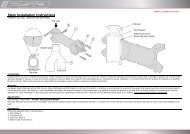
General Information Gates/Rohloff - Koga Signature
General Information Gates/Rohloff - Koga Signature
General Information Gates/Rohloff - Koga Signature

You also want an ePaper? Increase the reach of your titles
YUMPU automatically turns print PDFs into web optimized ePapers that Google loves.
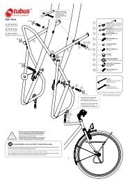
Manual for the <strong>Gates</strong> Carbon Drive<br />
System used with the <strong>Rohloff</strong><br />
SPEEDHUB 500/14
Content<br />
Congratulations! 4<br />
For your safety 4<br />
Examples of improper handling 6<br />
Uncoiling the belt 7<br />
Examples of improper handling when mounting the drive belt 8<br />
Dismounting the rear wheel / Mounting the rear wheel 9<br />
Mounting the <strong>Gates</strong> Carbon Drive Belt 11<br />
Checking the belt tension / Checking the belt tension using the Tension Tester 15<br />
Checking the belt tension without the Tension Tester / Using the Snubber to keep the <strong>Gates</strong> Carbon Drive Belt from ratcheting 17<br />
Snubber assembly / Mounting the Snubber 18<br />
Removing the Snubbers / Mounting the <strong>Gates</strong> Carbon Drive Front Sprocket 20<br />
Mounting the Front Sprocket at the crank adapter 21<br />
Mounting the <strong>Gates</strong> Carbon Drive Hybrid Rear Sprocket M46x6 23<br />
Mounting the Rear Sprocket M46x6 to the <strong>Gates</strong>-<strong>Rohloff</strong> Carrier M46x6 24<br />
Retrofitting the rear sprocket to a <strong>Rohloff</strong> SPEEDHUB 26<br />
Retrofitting the rear sprocket to a <strong>Rohloff</strong> SPEEDHUB 500/14 with chain pinion 26<br />
Removing the Rear Sprocket M46x6 with <strong>Gates</strong>-<strong>Rohloff</strong> Carrier M46x6 from <strong>Rohloff</strong> SPEEDHUB 500/14 27<br />
Removing the <strong>Gates</strong>-<strong>Rohloff</strong> Carrier from the <strong>Rohloff</strong> SPEEDHUB 500/14 28<br />
Removing the <strong>Gates</strong>-<strong>Rohloff</strong> Carrier from the rear sprocket 29<br />
When does the <strong>Gates</strong> Carbon Drive Belt need to be replaced, when do the sprockets need to be replaced? 31<br />
Replacing the belt after it has been damaged 31<br />
Replacing the Sprockets when they have been damaged / Replacing belt and sprockets because of abrasion 32<br />
Anforderungen an den Fahrradrahmen zur Montage des <strong>Gates</strong> Carbon Drives / Possibilities for tensioning and adjustment 35<br />
Straightness and stiffness of the frame 36<br />
Comparing the gear ratio of a <strong>Rohloff</strong> SPEEDHUB 500/14 with a <strong>Gates</strong> Carbon Drive System to a derailleur 38<br />
Comparing the gear ratio of <strong>Rohloff</strong> SPEEDHUB 500/14 chain pinion to <strong>Gates</strong> Carbon Drive Sprocket 38<br />
Tables of distance traveled per crank revolution for <strong>Rohloff</strong> SPEEDHUB 500/14 with <strong>Gates</strong> Carbon Drive Sprockets 39<br />
Comparing the gear ratio of a derailleur system to the <strong>Rohloff</strong> SPEEDHUB 500/14 with <strong>Gates</strong> Carbon Drive Sprocket 40<br />
GATES CARBON DRIVE SYSTEM Product Warranty 42<br />
2
1<br />
first steps<br />
• Congratulations!<br />
• For your safety<br />
• Examples of improper handling<br />
• Uncoiling the belt<br />
• Examples of improper handling when mounting the drive belt<br />
• Dismounting the rear wheel<br />
• Mounting the rear wheel<br />
www.carbondrivesystems.com<br />
3
first steps<br />
Congratulations!<br />
Thank you very much for choosing the <strong>Gates</strong> Carbon Drive System for your <strong>Rohloff</strong><br />
SPEEDHUB 500/14 drive hub. This manual will provide you with all the information necessary<br />
for a carefree use of this innovative drive system. If you still have questions about the <strong>Gates</strong><br />
Carbon Drive System after reading this manual, please contact your retailer or check<br />
www.carbondrivesystems.com for further information.<br />
Please note:<br />
We ask you to read this manual thoroughly and completely before you remove the <strong>Gates</strong><br />
Carbon Drive components from the packaging, start the installation of the components, or<br />
use a bike equipped with this drive system. Please follow all the instructions and steps in this<br />
manual carefully and keep the manual in a safe place for future reference.<br />
For your safety<br />
Before you ride your bike, always check if the drive belt is properly adjusted and tightened,<br />
and if the sprockets are bolted down tightly. Also, check if the Snubber is mounted correctly.<br />
Improperly adjusted drive belts might come off the sprockets when you ride the bike. The<br />
sprockets and/or the Snubber can also loosen during the ride if they are not tightened<br />
sufficiently. Incorrect mounting of the drive system can cause accidents and severe injuries.<br />
Please always follow all of the handling instructions for the drive belt, especially when you<br />
mount or dismount your rear wheel. This is where extra care is needed to avoid damaging<br />
the belt.<br />
Make sure that body parts do not get between belt and sprockets. Also watch out for any<br />
clothing, like turnups on pants, that might become caught in the drive system. When you<br />
ride the bike, make sure that you wear appropriate functional clothing.<br />
Please use only original parts and tools to ensure their compatibility.<br />
Follow all of the specific manufacturers’ instructions for installing and maintaining the<br />
components of your bike. Improper mounting and maintenance of components may cause<br />
severe injuries. Therefore, it is recommended to always have the components installed and<br />
maintained by a qualified mechanic.<br />
4
first steps<br />
1<br />
Have your bike checked regularly for safety at a service center that is certified for the<br />
mounting and maintenance of the <strong>Gates</strong> Carbon Drive System and the <strong>Rohloff</strong> Speedhub<br />
500/14.<br />
After an accident, check your bike for damaged parts and damage to the drive system.<br />
If you cannot be sure that the parts are all damage free, replace the components in<br />
question.<br />
Make sure that no other bicycle components or objects can come into contact with the<br />
Carbon Drive Belt or driveline of the bicycle when transporting the bike, e.g. in the trunk of<br />
a car, or whilst being transported with other bicycles on a ski-lift/gondola etc. Be especially<br />
careful when your bike is being transported with the rear wheel dismounted.<br />
The <strong>Gates</strong> Carbon Drive System is only approved as a drive system for bicycles which<br />
meet the requirements mentioned in the chapter “Requirements for the frame”. The <strong>Gates</strong><br />
Carbon Drive System is not approved for use on tandem or multi-rider bicycles.<br />
Universal Transmissions GmbH, CD Enterprises and <strong>Gates</strong> Corporation assume no liability<br />
for malfunctions or injuries caused by improper mounting or improper maintenance<br />
Please note:<br />
The Carbon Drive System is not suitable for retrofitting bikes that have not been<br />
engineered, designed and built especially for the Carbon Drive system. Only the perfect<br />
interaction of Carbon Drive System, crank, bottom bracket unit, hub, dropouts, and frame<br />
gate, as well as suited clamping and guidance elements allow for a safe and correct<br />
operation. The manufacturer of the frame or bicycle is responsible for choosing the correct<br />
components and verifying their proper function/operation.<br />
Please note:<br />
Please be aware that use of the <strong>Gates</strong> Carbon Drive system in ice and snow, can lead to<br />
the teeth of the pulleys becoming clogged. This can lead to the belt being pushed off of<br />
the pulley, or lifted up and ratcheting over it. Both of these possibilities could reduce the<br />
safe operation of the system. For this reason, the use of the bike in snow and ice should<br />
be avoided. The use of the system in clay based mud should also be avoided for the same<br />
reasons.<br />
www.carbondrivesystems.com<br />
5
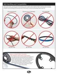
first steps<br />
Examples of<br />
improper handling<br />
The following illustrations<br />
show examples for improper<br />
handling of the drive belt.<br />
The manipulation illustrated<br />
damages the belt. A belt<br />
which has been damaged<br />
due to improper handling<br />
may fail during operation<br />
and cause an accident,<br />
injury or inconvenience.<br />
It should be clear that a<br />
damaged or mishandled<br />
belt can no longer be used.<br />
Crimping<br />
Twisting<br />
Back bending<br />
Inverting<br />
Zip tying<br />
Using as a wrench<br />
6
first steps<br />
1<br />
Mounting the tensioned belt with a lever, and/or by rotating the cranks.<br />
Please note:<br />
Drive belt and sprockets do not need lubrication of any sort. For cleaning, use only water<br />
and a soft brush. Please do not use any type of detergent.<br />
Uncoiling the belt<br />
To uncoil the belt, follow the instructions below. Improper uncoiling may cause permanent<br />
damage to the belt. It will never be necessary to violently pull the belt. Make sure that the<br />
belt is never bent to smaller diameters, as this might damage the carbon fibers inside the<br />
belt.<br />
Hold the belt chest high in<br />
front of your body.<br />
Hold the outer coils with<br />
both hands.<br />
Move your hands away<br />
from each other slowly,<br />
until the belt uncoils on its<br />
own.<br />
Now the belt is properly<br />
uncoiled.<br />
www.carbondrivesystems.com<br />
7
first steps<br />
Examples of improper handling when mounting the drive belt<br />
1. 2.<br />
3. 4.<br />
5. 6.<br />
8
first steps<br />
1<br />
7. 8.<br />
1. Drive belt next to sprocket<br />
2. Consistency, lets stick to one word-<br />
Securing the belt with Zip ties.<br />
3. Clamping belt in the dropout<br />
4. Clamping belt behind the crank<br />
5. Drive belt above Snubber wheel<br />
6. Stepping on the belt<br />
7. Clamping belt to the frame<br />
8. Using pliers<br />
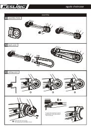
Dismounting the rear wheel<br />
Illustration 1:<br />
Before mounting / dismounting<br />
the rear wheel<br />
To dismount the rear wheel, you need to follow the steps below one at-a-time.<br />
Separate the <strong>Rohloff</strong> SPEEDHUB500/14 shifter. Look up the procedure for your version of<br />
the hub in your <strong>Rohloff</strong> SPEEDHUB500/14 manual.<br />
Loosen the long torque arm (if used in your model) according to the <strong>Rohloff</strong> SPEEDHUB<br />
500/14 manual.<br />
Push the Snubber wheel to the right latching position on the axle. (Illustration 1)<br />
Illustration 1: before mounting/ dismounting the rear wheel<br />
If applicable, unhinge the bowden cable of the rim brake.<br />
Loosen the quick release skewers or axle nut, and take the wheel from the dropouts.<br />
Remove the belt from the rear sprocket. Make sure you handle the belt carefully according<br />
to the instructions for proper handling of the belt.<br />
Mounting the rear wheel<br />
Check the fit of the Snubber in the right latching position of the axle according to<br />
illustration 1 of the instructions for Dismounting the rear wheel. Hang the drive belt over<br />
the bottom bracket of the frame and follow the instructions for Mounting the <strong>Gates</strong><br />
Carbon Drive Belt (start at step 4).<br />
www.carbondrivesystems.com<br />
9
2<br />
mounting<br />
• Mounting the <strong>Gates</strong> Carbon Drive Belt<br />
• Checking the belt tension<br />
• Checking the belt tension using the Tension Tester<br />
• Checking the belt tension without the Tension Tester<br />
• Using the Snubber to keep the <strong>Gates</strong> Carbon Drive Belt from ratcheting<br />
• Snubber assembly<br />
• Mounting the Snubber<br />
• Removing the Snubbers<br />
• Mounting the <strong>Gates</strong> Carbon Drive Front Sprocket<br />
• Mounting the Front Sprocket at the crank adapter<br />
• Mounting the <strong>Gates</strong> Carbon Drive Hybrid Rear Sprocket M46x6<br />
• Mounting the Rear Sprocket M46x6 to the <strong>Gates</strong>-<strong>Rohloff</strong> Carrier<br />
M46x6<br />
• Retrofitting the rear sprocket to a <strong>Rohloff</strong> SPEEDHUB<br />
• Retrofitting the rear sprocket to a <strong>Rohloff</strong> SPEEDHUB 500/14 with chain<br />
sprocket<br />
• Removing the Rear Sprocket M46x6 with <strong>Gates</strong>-<strong>Rohloff</strong> Carrier M46x6<br />
from <strong>Rohloff</strong> SPEEDHUB 500/14<br />
• Removing the <strong>Gates</strong>-<strong>Rohloff</strong> Carrier from the <strong>Rohloff</strong> SPEEDHUB 500/14<br />
• Removing the <strong>Gates</strong>-<strong>Rohloff</strong> Carrier from the rear sprocket<br />
10
mounting<br />
Mounting the <strong>Gates</strong> Carbon Drive Belt<br />
2<br />
The following steps describe how to mount the belt in a bike with already mounted sprockets.<br />
If your sprockets have not been mounted yet, please follow the instructions for Mounting front<br />
and rear sprockets first. If you have any difficulties with mounting the belt, the video at<br />
www.carbondrivesystems.com will help you.<br />
1. Open the frame break or ‘gate’ on the<br />
frame’s rear triangle. Since this break<br />
may vary from one manufacturer to<br />
another, you’ll need to follow the<br />
instructions of the manufacturer<br />
of your frame. In the following<br />
illustrations the frame is opened at<br />
the dropout.<br />
Insert the belt through the opening<br />
of the frame.<br />
2. Hang the belt over the bottom<br />
bracket and lock the frame gate.<br />
3. Place the belt on the rear sprocket<br />
and mount the rear wheel into the<br />
rear dropouts.<br />
www.carbondrivesystems.com<br />
11
mounting<br />
Minimize the distance between<br />
the axle of the bottom bracket and<br />
the rear axle so that the belt can be<br />
fitted to the front sprocket without<br />
tension. The tools requird to reduce<br />
the distance may vary depending<br />
upon manufacturer. Always follow<br />
the instructions of the particular<br />
manufacturer. In this example, the rear wheel is moved towards the bottom bracket<br />
by horizontally slidable dropouts. It might be necessary to loosen the screws of the<br />
disc brake caliper. When you reach the smallest distance between the axle of the<br />
bottom bracket and the rear axle, fit the belt to the front sprocket as well.<br />
4. Devices used to tension the belt may vary by manufacturer. Always follow the<br />
instructions of the particular manufacturer. In this example, you now tension the<br />
belt on the drive side, using the slidable dropouts and the tensioning bolts inside<br />
the dropouts. After tensioning the right side (drive side), until the wheel sits evenly<br />
between both chainstays.<br />
Please Note:<br />
Never try to pry the belt on, or “roll” it on by rotating the cranks. This may cause inner<br />
structual damage which will result in the belt no longer being useful.<br />
The handling illustrated above can damage the system!<br />
12
mounting<br />
2<br />
Illustration 3:<br />
Correct alignment of the belt<br />
Illustration 4:<br />
Incorrect alignment of the<br />
belt<br />
5. Rotate the cranks 10-15 times and<br />
check the alignment of the belt. The<br />
belt should slightly touch, or come<br />
just short of touching the inside<br />
flange of the rear sprocket (within<br />
1mm). A constant distance of 0.5mm<br />
between belt and flange is<br />
recommended.<br />
6. Tension the dropouts on the drive side or loosening them on the non-drive side steers<br />
the belt towards the flange of the rear sprocket. Adjust the rear wheel to achieve the<br />
right alignment of the belt. Turn the crank again, re-check the belt alignment and readjust,<br />
if necessary. Make sure to maintain the proper belt tension. Repeat this step until<br />
you reach the perfect belt alignment.<br />
7. Reconnect the torque arm (if used with your version) and the gear mech of the hub.<br />
Please follow the instructions of the <strong>Rohloff</strong> SPEEDHUB500/14 manual for your<br />
version of the hub. Tighten all bolts of the rear wheel and quick release elements,<br />
according to the manufacturer’s torque specifications.<br />
8. If you have loosened the bolts of the brake caliper for the mounting, make sure to retighten<br />
them now. If you have unhinged the bowden cable of your brake, be sure to put<br />
it back.<br />
www.carbondrivesystems.com<br />
13
mounting<br />
9. If the belt does not align with the front and rear flanges of the sprockets after<br />
tightening all the bolts, one of the following actions will help you:<br />
a. Adjustment of the belt alignment by fine adjustment of the rear wheel<br />
b. Adjustment of the belt alignment at the crank (see Mounting the front sprocket)<br />
10. Now follow the instructions for checking the belt tension.<br />
11. Finally, check to make sure that the Snubber is correctly mounted.<br />
Please note:<br />
The following instructions are for frames with horizontally slidable dropouts. These are<br />
used differently by various different manufacturers. Fora different frame version than<br />
described in the following example, please follow the instructions of the particular<br />
manufacturer, or ask your certified retailer how to align and tension the belt.<br />
Aligning the belt by adjusting the slidable dropouts<br />
14
mounting<br />
Checking the belt tension<br />
2<br />
Proper belt tension is essential for optimum operation of the <strong>Gates</strong> Carbon Drive System.<br />
Lack of belt tension can lead to so-called “ratcheting“. The teeth of the belt will slide over<br />
the teeth of the rear sprocket. This causes not only an unpleasant sound, the ratcheting<br />
can also cause damage to the carbon tensile cords. This would render a belt useless. If<br />
ratcheting has occurred you should replace the belt before the next time it is to be used.<br />
Too much tension can also cause damage to the bearings within the rear hub. It also<br />
increases the wear of your drive system and the system can drag.<br />
Checking the belt tension using the Tension Tester<br />
1. Construction: The Tension Tester (Art. No 10400009, illustration 1) has a black plastic<br />
measurement arm, located in a slot. Along this slot there is a measuring scale. The<br />
point of intersection of the measurement arm and the measuring scale shows the<br />
tension of the belt. There is a button (clicking pad) on the upper side of the Tension<br />
Tester, where you can secure your finger with a rubberband holder. A spring is located<br />
underneath this clicking pad. If a certain pressure is applied to the spring, it makes a<br />
clicking sound.<br />
2. The underside of the Tension Tester incorporates a guide rail to help position the<br />
Tester correctly along the length of the belt.<br />
Scale in kg<br />
Securing the Tension<br />
Tester (Art. No 10400009)<br />
Location of the<br />
measurement arm before<br />
each measurement<br />
process<br />
www.carbondrivesystems.com<br />
15
mounting<br />
Measuring the belt<br />
tension using the Tension<br />
Tester<br />
Location of the<br />
measurement arm,<br />
when correct tension is<br />
achieved<br />
Tension Tester with a<br />
numeric scale<br />
3. The Tension Tester allows you to check the tension easily and quickly. Secure one<br />
finger between clicking pad and rubber band holder. Before each measuring process<br />
the measurement arm has to be pressed into the slot completely.<br />
4. Press the Tension Tester steadily to the middle of the upper side of the belt. The “lip”<br />
will lead the tester to the belt. Now slowly increase the pressure on the tester, until you<br />
hear a clicking sound. Do not increase the pressure after the tester has clicked. Now<br />
remove the tester carefully from the belt. Avoid jerky movements and canting the<br />
tester, as this would distort the result of the measurement.<br />
16
mounting<br />
Checking the belt tension without the Tension Tester<br />
2<br />
Should you need to check or adjust the tension of the belt and a Tension Tester is unavailable,<br />
you can apply the force deflection method. This method is not as accurate as using a<br />
Tension Tester, but it is still better than not checking the tension at all.<br />
1. Press down on the upper side of the belt between front and rear sprocket with your<br />
finger, and exert a force of 20 to 45N (2-4.5 kg). The correct tension is achieved if this<br />
force can move the belt down by approximately 10mm.<br />
2. Since the tension may vary a little along the belt, you should repeat this procedure<br />
several times. Rotate the cranks a quarter turn after each measurement and measure<br />
again.<br />
3. If the tension of the belt is too high or too low, adjust the tension until the<br />
measurement result is good.<br />
Please note:<br />
This re-adjustment of the belt tension is done with the tensioning mechanism of the frame.<br />
In this example it is done with the adjustment bolts of the dropouts. Proceed as you did<br />
when Mounting the <strong>Gates</strong> Carbon Drive Belt, this means the correct alignment of the belt<br />
has to be guaranteed at all times while you adjust the tension. You have to adjust both, the<br />
alignment and the tension.<br />
Using the Snubber to keep the <strong>Gates</strong> Carbon Drive Belt from<br />
ratcheting<br />
If the <strong>Gates</strong> Carbon Drive is used with the <strong>Rohloff</strong> SPEEDHUB 500/14, a so-called “Snubber”<br />
has to be installed. The Snubber guides the belt at the rear sprocket and prevents the belt<br />
from ratcheting over the teeth. Ratcheting teeth can damage the inner carbon structure of<br />
the belt. This can cause the belt to break when the bike is being used. If you think that the<br />
inner structure of your belt might be damaged, you should replace the belt<br />
www.carbondrivesystems.com<br />
17
mounting<br />
Snubber assembly<br />
Title<br />
Part Number<br />
CD-RDM-Snubber 10001400<br />
M10x1x12 Snubber-bolt 11002001<br />
Snubber-plate 11002002<br />
Snubber-axle 11002003<br />
Snubber-spring pin 11002004<br />
Snubber-spring 11002005<br />
Snubber-wheel 11002006<br />
Snubber-snap fit 11002007<br />
Snubber-Clip-DIN6799-RA8 11202008<br />
Snubber-long slot bolt 11202009<br />
Snubber-long slot washer 11202010<br />
Mounting the Snubber<br />
Illustration 1:<br />
<strong>Rohloff</strong> SPEEDHUB 500/14<br />
with Snubber<br />
Distance: 1-1,5 mm<br />
Illustration 2:<br />
The Snubber wheel does<br />
not touch the belt!<br />
1. The following illustration shows the Snubber<br />
mounted to the derailleur hanger. To mount the<br />
Snubber, you have to affix the Snubber plate in the<br />
thread of the derailleur hanger with a M10x1 screw.<br />
Then you have to affix the slidable Snubber axle to<br />
the Snubber plate with a M4 screw. The Snubber<br />
wheel is located on the Snubber axle. The Snubber<br />
wheel is slidable on the Snubber axle. The Snubber<br />
wheel latches into an inner and an outer catch<br />
position on the axle, to ease the dismounting of the<br />
wheel. The Snubber does not influence the degree<br />
of efficiency or the smooth operation of the belt, as<br />
it does not touch the belt. The Snubber is only for<br />
safety purposes.<br />
2. The Snubber plate is screwed to the derailleur hanger<br />
with an M10x1 screw. The correct position is shown<br />
in illustration 2. The center pin support has to be<br />
pushed against the locating surface of the derailleur<br />
hanger. The Snubber axle can be adjusted in an<br />
elongated slot and it can be affixed with a M6 screw.<br />
The Snubber wheel can be slid along the Snubber<br />
18
mounting<br />
axle. If the Snubber is located in the left position, it is<br />
active and can keep the belt from ratcheting, since the<br />
belt cannot slide across the teeth of the rear sprocket.<br />
When you adjust the position of the Snubber wheel,<br />
make sure that the wheel does not touch the belt.<br />
2<br />
Illustration 3:<br />
Side view of the installed<br />
Snubber<br />
3. By moving the Snubber axle in the elongated slot<br />
of the Snubber plate, you can adjust the distance<br />
between the Snubber wheel and the belt. This<br />
distance should be between 1mm and 1.5mm.<br />
Circlip<br />
Locating Surface<br />
Snubber<br />
Snubberaxle<br />
Derailleur Hanger<br />
Left Detent<br />
Right Detent<br />
M6 Bolt<br />
Pin (4mm)<br />
Illustration 4:<br />
Parts of the Snubbers<br />
Please note:<br />
The Snubber, which is used as an example here, is one possibility to keep the drive belt<br />
from ratcheting. Different constructions are possible and used for bikes from other<br />
manufacturers. However, any other system has to be checked for its functionality and safety<br />
and has to be approved by both <strong>Rohloff</strong> and <strong>Gates</strong>.<br />
www.carbondrivesystems.com<br />
19
mounting<br />
Snubber version for quick<br />
release, vertical dropout use<br />
without a derailleur hanger<br />
Removing the Snubbers<br />
Follow the instructions for Mounting the Snubber in the reversed order.<br />
Mounting the <strong>Gates</strong> Carbon Drive Front Sprocket<br />
Front sprockets are available for the <strong>Gates</strong> carbon Drive System to fit both<br />
4 and 5 arm crank-sets.<br />
Front Sprocket versions<br />
Teeth Description Part Number<br />
46 4-Arm 104mm BC 11464AF10<br />
50 4-Arm 104mm BC 11504AF10<br />
55 5-Arm 130mm BC 11555AF10<br />
60 5-Arm 130mm BC 11605AF10<br />
Teeth<br />
Front Sprocket (shown<br />
here: 55 tooth/5-Arm)<br />
Flange<br />
Locating Holes<br />
20
mounting<br />
2<br />
Shim ring for bottom<br />
bracket<br />
Art.Nr. 11201023<br />
Shim ring 0.5mm<br />
Art.Nr. 11201020<br />
Shim ring 1mm<br />
Art.Nr. 11201022<br />
Mounting the Front Sprocket at the crank adapter<br />
The sprocket is put over the crank arm and affixed with the sprocket bolts (which were<br />
included with your crankset). As shown in illustration 1, the flange of the sprocket is turned<br />
outward. To guarantee proper operation of the <strong>Gates</strong> Carbon Drive System, both sprockets<br />
need to be exactly aligned with each other (illustrations 2 and 3). The belt alignment cannot<br />
be adjusted on the rear sprocket of the <strong>Rohloff</strong> SPEEDHUB 500/14. Therefore, you can<br />
only adjust it with the position of the front sprocket. The included shim rings have been<br />
designed to facilitate this adjustment. For some bottom brackets it is possible to adjust the<br />
alignment with shim rings (illustration 4). Please note the mounting instructions from the<br />
particular bottom bracket manufacturer.<br />
Chain-ring Nut<br />
Crank Arm<br />
Illustration 1:<br />
Mounting the front<br />
sprocket<br />
Chain-ring Bolt<br />
Mounting Shims<br />
(if required)<br />
Front Sprocket<br />
www.carbondrivesystems.com<br />
21
mounting<br />
Illustration 2:<br />
Sprocket alignment<br />
Illustration 3:<br />
Aligning the front<br />
sprocket<br />
Illustration 4:<br />
Adjusting the belt<br />
alignment with shim rings<br />
at the bottom bracket<br />
Crank with Belt Polley<br />
Mounting Shim for Bottom<br />
Bracket (if required)<br />
Bearing Cup<br />
Bottom Bracket Axle<br />
Removing the front sprocket<br />
Follow the instructions for the Mounting the front sprocket in the<br />
reversed order.<br />
22
mounting<br />
Mounting the <strong>Gates</strong> Carbon Drive Hybrid Rear Sprocket M46x6<br />
2<br />
The <strong>Gates</strong> Carbon Drive Hybrid Rear Sprocket M46x6 allows you to mount the <strong>Gates</strong><br />
Carbon Drive System to a carrier which will make it compatible to a variety of rear hubs. In<br />
this case to the <strong>Rohloff</strong> SPEEDHUB 500/14.<br />
Teeth<br />
Part Number<br />
19 10001319<br />
20 10001320<br />
22 10001322<br />
24 10001324<br />
Flange<br />
Rear Sprocket M46x6<br />
Teeth<br />
M 46x6 Thread<br />
<strong>Gates</strong>-<strong>Rohloff</strong> Carrier<br />
M46x6 Art. Nr. 8224<br />
Company - <strong>Rohloff</strong><br />
Cone Wrench SW46<br />
Art. Nr. 10400007<br />
<strong>Rohloff</strong> Sprocket Remover<br />
Art.Nr.8501<br />
Company - <strong>Rohloff</strong><br />
www.carbondrivesystems.com<br />
23
mounting<br />
Flat Wrench SW46<br />
Art. Nr. 10400006<br />
POM-Sprocket-Key<br />
Art. Nr. siehe Tabelle<br />
Title<br />
Part Number<br />
Basiswerkzeug 10400001<br />
Aufsatz 19 Zähne 10400002<br />
Aufsatz 20 Zähne 10400003<br />
Aufsatz 22 Zähne 10400004<br />
Aufsatz 24 Zähne 10400005<br />
Mounting the Rear Sprocket M46x6 to the <strong>Gates</strong>-<strong>Rohloff</strong> Carrier<br />
M46x6<br />
The <strong>Gates</strong>-<strong>Rohloff</strong> Carrier M46x6 by <strong>Rohloff</strong> (Art. No. 10300101) is where the <strong>Gates</strong> Carbon<br />
Drive System and the <strong>Rohloff</strong> SPEEDHUB 500/14 (Illustration 1) come together. At the time<br />
of delivery the <strong>Gates</strong> Carrier may already be fitted to the hub. If this is not the case, please<br />
follow the instructions for retrofitting the carrier to your hub.<br />
Illustration 1:<br />
<strong>Rohloff</strong> SPEEDHUB 500/14<br />
with <strong>Gates</strong>-<strong>Rohloff</strong> Carrier<br />
M46x6 and Rear Sprocket<br />
M46x6<br />
24
mounting<br />
Lubricate the inner thread of the Rear Sprocket M46x6 and carefully screw it on to the<br />
Carrier as far as possible by hand (illustration 3). As shown in illustration 3, the flange of<br />
the rear sprocket needs to be on the hub side. Make sure to bring the parts together in<br />
the right angle and do not cant them. Tighten the Rear Sprocket M46x6 with the POM-<br />
Sprocket-Key (Art. No. 10400001, 1040000X), to keep the sprocket and the Carrier from<br />
loosening from the hub in future mounting processes. To keep the hub from rotating<br />
while you thread on the carrier, you may hold the driver (sprocket thread) in place with the<br />
<strong>Rohloff</strong> Sprocket Tool and an Open-end Wrench SW24 (illustration5). Always make sure that<br />
the <strong>Rohloff</strong> Sprocket tool is seated correctly and secured in place.<br />
2<br />
Please note:<br />
Always secure the Sprocket tool, as described in the <strong>Rohloff</strong> Owners Manual (chapter<br />
Service, paragraph 3 „Sprocket reversing/replacing“), using a quick release skewer (CC<br />
versions), or an axle nut (TS versions), to avoid damage to the driver (sprocket thread).<br />
(Illustration 2).<br />
Illustration 2:<br />
Securing the <strong>Rohloff</strong><br />
Sprocket tool with quick<br />
release skewer or axle nut<br />
Illustration 3:<br />
<strong>Rohloff</strong> SPEEDHUB 500/14<br />
with <strong>Gates</strong> <strong>Rohloff</strong> Carrier<br />
M46x6 and Rear Sprocket<br />
M46x6<br />
www.carbondrivesystems.com<br />
25
mounting<br />
Retrofitting the rear sprocket to a <strong>Rohloff</strong> SPEEDHUB<br />
Illustration 4:<br />
Putting the POM-<br />
Sprocket-Key on the Rear<br />
Sprocket M46x6<br />
Illustration 5:<br />
Tightening the rear sprocket<br />
with the POM-Sprocket-Key<br />
and using the Open-end<br />
wrench SW24 to hold the<br />
<strong>Rohloff</strong> Sprocket tool in<br />
place.<br />
Please note:<br />
Only the POM-Sprocket-Key (Art. No. 10400001, 1040000X) is to be used for tightening/<br />
loosening the rear sprocket. Never use pliers, a channel lock or similar, as they could<br />
damage the protective coating of the sprockets. Using the belt as a tool can damage it<br />
and it will not function properly afterwards. An alternative method of tightening the rear<br />
sprocket, is to exert pressure on the pedals in the 3 o’clock position when the rear wheel is<br />
mounted and the belt is installed. Please have the rear-wheel brake on for this procedure.<br />
(Illustration 6).<br />
Illustration 6:<br />
Alternative tightening<br />
of the Rear Sprocket by<br />
exerting pressure on the<br />
pedal when rear-wheel<br />
brake is on.<br />
26<br />
Retrofitting the rear sprocket to a <strong>Rohloff</strong> SPEEDHUB 500/14 with chain<br />
pinion<br />
First remove the rear sprocket from the <strong>Rohloff</strong> SEEDHUB 500/14 and replace it with the<br />
<strong>Gates</strong>-<strong>Rohloff</strong> Carrier M34x6.<br />
After you have successfully removed the chain sprocket (see <strong>Rohloff</strong> Owners Manual<br />
chapter Service, paragraph 3 Sprocket reversing/replacing“), clean the driver (sprocket<br />
thread), and lubricate the inner thread of the <strong>Gates</strong> Carrier M34x6.
mounting<br />
Ensure that the surfaces of the Carrier touching the <strong>Rohloff</strong> hub are clean and free<br />
of scratches. These two components together form the seal that hinders the oil from<br />
leaking out. Now carefully screw the Carrier on clockwise as far as possible by hand<br />
(illustration 7). The M46x6 outer thread has to be turned away from the hub. Please<br />
consult the instructions for using the Sprocket tool in the <strong>Rohloff</strong> Owners Manual.<br />
Afterwards follow the instructions above.<br />
2<br />
Removing the Rear Sprocket M46x6 with <strong>Gates</strong>-<strong>Rohloff</strong> Carrier<br />
M46x6 from <strong>Rohloff</strong> SPEEDHUB 500/14<br />
Please note:<br />
As oil may leak from the hub when you remove the chain sprocket from the <strong>Rohloff</strong><br />
SPEEDHUB 500/14, the driver side of the hub should be turned upward, if possible.<br />
M 34x6 Thread<br />
Illustration 7:<br />
Installing the <strong>Gates</strong>-<br />
<strong>Rohloff</strong> Carrier M46x6 to<br />
the M34x6 thread of the<br />
driver<br />
Driver<br />
Please note:<br />
When you remove the rear sprocket from the <strong>Rohloff</strong> SPEEDHUB 500/14, it is impossible<br />
to know if the rear sprocket will detach from the Carrier first, or if both components<br />
detach from the hub at the same time. Depending on which is the case, follow the<br />
particular instructions for separating the components.<br />
As described in paragraph 3 “Sprocket reversing/replacing” in the chapter Service, of<br />
the <strong>Rohloff</strong> Owners Manual, place the Sprocket tool onto the driver (sprocket thread)<br />
and secure it in position with the quick release skewer (CC Versions), or the axle nut (TS<br />
Versions). Hold the Sprocket tool with the Open-end Wrench SW24 and loosen the rear<br />
sprocket with the POM-Sprocket-Key (Art. No. 10400001, 1040000X) by turning it in the<br />
opposing direction. (Illustration 8).<br />
www.carbondrivesystems.com<br />
27
mounting<br />
Illustration 8:<br />
Mounting the <strong>Gates</strong> –<br />
<strong>Rohloff</strong> Carrier M46x6<br />
onto the M34x6 thread<br />
of the SPEEDHUB 500/14<br />
driver.<br />
Removing the <strong>Gates</strong>-<strong>Rohloff</strong> Carrier from the <strong>Rohloff</strong><br />
SPEEDHUB 500/14<br />
The <strong>Rohloff</strong> Sprocket tool, secured with a quick release skewer or an axle nut, is locked in<br />
place by the open-end wrench SW24. You can now loosen the <strong>Gates</strong>-<strong>Rohloff</strong> Carrier with<br />
a Flat Wrench (Art. No. 10400006) by turning it in the opposing direction to the driver, as<br />
shown in illustration 9. To loosen the carrier, exert a sudden pressure on the Flat Wrench<br />
SW24 in the opposite direction as the driver.<br />
Illustration 9:<br />
Removal of the <strong>Gates</strong> -<br />
<strong>Rohloff</strong> Carrier from the<br />
SPEEDHUB 500/14<br />
Please note:<br />
Always secure the Sprocket tool as described in the <strong>Rohloff</strong> Owners Manual (chapter<br />
Service, paragraph 3 „Sprocket reversing/replacing“), using a quick release skewer (CC<br />
versions), or an axle nut (TS versions), to avoid damage to the driver (sprocket thread).<br />
28
mounting<br />
Removing the <strong>Gates</strong>-<strong>Rohloff</strong> Carrier from the rear sprocket<br />
2<br />
To remove the Carrier from the rear sprocket, you must secure the POM-Sprocket-Key (Art.<br />
No. 10400001, 1040000X) in a bench vice, the opening turned upward (illustration 10),<br />
and place the rear sprocket into the spanner socket. Turn the Cone Wrench SW46 (Art. No.<br />
10400007, illustration 11) counter clockwise to loosen the Carrier (illustration 12).<br />
Illustration 10:<br />
POM-Sprocket-Key<br />
Illustration 11:<br />
Cone Wrench SW46<br />
Illustration 12:<br />
Removing the <strong>Gates</strong>-<br />
<strong>Rohloff</strong> Carrier from the<br />
Rear Sprocket<br />
www.carbondrivesystems.com<br />
29
3<br />
exchange<br />
• When does the <strong>Gates</strong> Carbon Drive Belt need to be replaced, when do<br />
the sprockets need to be replaced?<br />
• Replacing the belt after it has been damaged<br />
• Replacing the Sprockets when they have been damaged<br />
• Replacing belt and sprockets because of abrasion<br />
30
exchange<br />
When does the <strong>Gates</strong> Carbon Drive Belt need to be replaced,<br />
when do the sprockets need to be replaced?<br />
The durability of Carbon Drive System components depends on a number of exterior<br />
influences and conditions. The life expectancy of belt drive systems or common bike<br />
chains is always shorter in rough and muddy conditions, than when they are used in a dry<br />
environment. While the bike chain gets clogged with mud, the <strong>Gates</strong> Carbon Drive System<br />
generally stays clean. If a traditional chain is not lubricated correctly it will have a shorter<br />
lifespan. This is not the case with a belt, since it does not need any additional lubrication.<br />
3<br />
Illustration 1:<br />
The <strong>Gates</strong> Carbon Drive<br />
System used in a muddy<br />
environment<br />
Please note:<br />
When you first use your new <strong>Gates</strong> Carbon Drive System, the blue layer on the inside<br />
of the belt will wear off quickly. This is no abrasion of the belt. The blue layer is only for<br />
production-related purposes. It is a form release agent, used to make it easier to take the<br />
belt out of its form during the manufacturing process. It does not influence the function of<br />
the belt in any way.<br />
Replacing the belt after it has been damaged<br />
The <strong>Gates</strong> Carbon Drive Belt should always be replaced if it has been damaged through<br />
improper handling (see examples for improper handling), or if it has been damaged<br />
through severe exterior conditions. For example, if a stone, a root, or a piece of clothing<br />
has been caught in the belt and has been pulled between belt and sprocket. This can cause<br />
damage to the sensitive carbon fibers inside the belt, even if there is no damage visible<br />
from the outside. If a belt is damaged in this way or if you assume that there might be<br />
damage to the belt, you should always replace it, as it might suddenly rip when the bike is<br />
being used, and this can cause an accident or severe injury.<br />
www.carbondrivesystems.com<br />
31
exchange<br />
Illustration 2:<br />
Wearing off of the blue<br />
layer<br />
Replacing the Sprockets when they have been damaged<br />
The sprockets always need to be replaced if they have been damaged through severe use<br />
or exterior influences. If you ride over a rock, or a tree trunk, for example, and you bottom<br />
out hard with the front sprocket, it might deform and would have to be replaced. Stones<br />
caught between belt and sprocket can cause damage to the teeth of the belt. Teeth might<br />
break off partially or completely. When this happens, the particular sprocket has to be<br />
replaced. Whether or not the belt has to be replaced would have to be determined with<br />
the criteria mentioned above (Replacing the belt after it has been damaged).<br />
Replacing belt and sprockets because of abrasion<br />
Both the belt and sprockets are parts that abrade or wear. Contrary to what you might<br />
expect, tests have shown that the belt tends to have a slightly longer life expectancy<br />
than the sprockets. You can check the abrasion of belt and sprockets with the Profile<br />
Wear Gauge as shown in illustrations 3 and 4. If the gauge result is equal to, or larger than<br />
0.5mm, the particular belt or sprocket will need to be replaced. For a drive system in which<br />
all components have been used for the same amount of time it is recommended to replace<br />
all components, as soon as one of them needs to be replaced because of wear or abrasion.<br />
You can find further information about the use of your Profile Wear Gauge in the separate<br />
manual.<br />
32
exchange<br />
Profile Wear Gauge<br />
Illustration 3:<br />
Checking the abrasion of<br />
the belt<br />
3<br />
Belt<br />
Profile Wear Gauge<br />
Illustration 4:<br />
One-sided abrasion upon<br />
the teeth of the rear<br />
sprocket<br />
rear sprocket<br />
Please note:<br />
Small cracks on the back of the belt may occur after some amount of use. These are normal.<br />
If there are cracks at the dedendum (the radial distance between the pitch circle and the<br />
bottom of the tooth), however, the belt will need to be replaced.<br />
www.carbondrivesystems.com<br />
33
4<br />
for<br />
Frame builders<br />
• Frame requirements when mounting the <strong>Gates</strong> Carbon Drive<br />
• Possibilities for tensioning and adjustment<br />
• Straightness and stiffness of the frame<br />
34
for Frame builders<br />
Frame requirements when mounting the <strong>Gates</strong> Carbon Drive<br />
Opening the frame<br />
A specific rear triangle is required for mounting the <strong>Gates</strong> Carbon Drive System. Since<br />
the belt cannot be separated and rejoined like a bike chain, it has to be possible to open<br />
the frame at the rear triangle. This opening should allow a gap of at least 8mm. There are<br />
several possible solutions, depending upon desired style. Illustrations1 and 2 show a frame<br />
with the opening at the dropout. A separation of the right chainstay or at the seatstay of<br />
the frame is also possible. (Illustration 3).<br />
4<br />
Illustration 1:<br />
Opening the frame to<br />
mount the belt<br />
Possibilities for tensioning and adjustment<br />
It has to be possible to tension and adjust the belt after it is mounted in the frame. This<br />
ispossible through the use of either adjustable dropouts (illustration 2) or with an eccentric<br />
adjuster around the bottom bracket.<br />
However, the safety of the belt can only be guaranteed if the correctly adjusted tension is<br />
not altered when the rear wheel is dismounted (in the case of a puncture, for example). The<br />
frame construction must allow for this.<br />
www.carbondrivesystems.com<br />
35
for Frame builders<br />
Illustration 2:<br />
Example for frame<br />
construction<br />
Opening of the<br />
Frame<br />
Horizontally<br />
Adjustable Dropouts<br />
Axle Seat.<br />
Illustration 3:<br />
Example for frame<br />
construction: separation<br />
of the seat stay<br />
Straightness and stiffness of the frame<br />
For the smooth operation of the <strong>Gates</strong> Carbon Drive System, the frame needs to be<br />
straight and stiff. These requirements are specified in the <strong>Gates</strong> Technical Manual for Frame<br />
Builders. Furthermore, the adjustable range of lengths between bottom bracket housing<br />
and rear axle should be between 16 and 30mm, to guarantee a sufficient tensioning<br />
function and the possibility of changing the gear ratio.<br />
Please note:<br />
You can find all information and the frame construction requirements for using the <strong>Gates</strong><br />
Carbon Drive System in the <strong>Gates</strong> Technical Manual for Frame Builders Manual at<br />
www.carbondrivesystems.com.<br />
36
5<br />
Gear Ratio<br />
Comparisum<br />
• Comparing the gear ratio of a <strong>Rohloff</strong> SPEEDHUB 500/14 with a <strong>Gates</strong><br />
Carbon Drive System to a derailleur gear system<br />
• Comparing the gear ratio of a <strong>Rohloff</strong> SPEEDHUB 500/14 chain sprocket<br />
to a <strong>Gates</strong> Carbon Drive Sprocket<br />
• Tables of distance traveled per crank revolution for <strong>Rohloff</strong> SPEEDHUB<br />
500/14 with <strong>Gates</strong> Carbon Drive Sprockets<br />
• Comparing the gear ratio of a derailleur system to that of the <strong>Rohloff</strong><br />
SPEEDHUB 500/14 with <strong>Gates</strong> Carbon Drive Sprocket<br />
www.carbondrivesystems.com<br />
37
atio overview<br />
Comparing the gear ratio of a <strong>Rohloff</strong> SPEEDHUB 500/14 with a<br />
<strong>Gates</strong> Carbon Drive System to a derailleur gear system<br />
The overall gear ratio is 526%, meaning the highest gear is 5.26 times higher than the lowest<br />
gear. The 14 gears are evenly graded. The gear ratio of the <strong>Rohloff</strong> SPEEDHUB 500/14 can<br />
be adapted to certain conditions by varying the choice of front and rear sprockets. You can<br />
choose from the versions listed in the table below. As the number of new versions increases,<br />
an up-to-date selection of available sprockets can be found under<br />
www.carbondrivesystems.com for the complete selection.<br />
Teeth<br />
Part Number<br />
19 1119RAF10<br />
20 1120RAF10<br />
22 1122RAF10<br />
24 1124RAF10<br />
Versions of Rear<br />
Sprockets M46x6<br />
Teeth<br />
Part Number<br />
46 4 bolt 104mm BC 11464AF10<br />
50 4 bolt 104mm BC 11504AF10<br />
55 5 bolt 130mm BC 11555AF10<br />
60 5 bolt 130mm BC 11605AF10<br />
Versions of Front<br />
Sprockets<br />
Comparing the gear ratio of a <strong>Rohloff</strong> SPEEDHUB 500/14 chain<br />
sprocket to a <strong>Gates</strong><br />
The following table shows, which sprocket-size combination of chain sprockets for the<br />
<strong>Rohloff</strong> SPEEDHUB 500/14 equates to the possible combinations of the <strong>Gates</strong> Carbon Drive<br />
Sprocket. You can find the actual sprocket gear ratio in brackets.<br />
38
atio overview<br />
19 Teeth rear 20 Teeth rear 22 Teeth rear 24 Teeth rear<br />
46 teeth front (2,42) ≈ 42/17 not permitted not permitted not permitted<br />
50 teeth front (2,63) ≈ 42/16 (2,50) ≈ 40/16 not permitted not permitted<br />
55 teeth front (2,89) ≈ 46/16 (2,75) ≈ 44/16 (2,50) ≈ 40/16 not permitted<br />
60 teeth front (3,16) ≈ 50/16 (3,00) ≈ 48/16 (2,73) ≈ 46/17 (2,50) ≈ 40/16<br />
Please note:<br />
Smallest permitted belt gear ratio:<br />
The belt gear ratio of the <strong>Rohloff</strong> SPEEDHUB 500/14 converts the low number of<br />
revolutions of the crank to a high number of revolutions at the rear sprocket and reduces<br />
the incoming torque for the transmission in the same ratio. To exclude an overload of the<br />
transmission, the sprocket gear ratio must not be lower than 2.35. This equates to the<br />
sprocket-size combinations of 46/19, 50/20, 55/22, and 60/24. Bigger sprockets can be<br />
used without any restrictions.<br />
5<br />
Tables of distance traveled per crank revolution for <strong>Rohloff</strong><br />
SPEEDHUB 500/14 with <strong>Gates</strong> Carbon Drive Sprockets<br />
In the following tables the distance traveled per crank revolution is measured in meters<br />
for the 1st and the 14th gear of the <strong>Rohloff</strong> SPEEDHUB 500/14 respectively. Depending on<br />
the given gear ratio of the belt, the possible distances traveled per crank revolution for the<br />
common wheel circumferences (20”, 26”, and 28”) can be read out. The tables are based on<br />
the following context:<br />
Distance traveled per crank<br />
revolution<br />
= U x F x Ü Getr.<br />
R<br />
The formula consists of:<br />
U = wheel circumference<br />
F = amount of teeth of the front sprocket<br />
R = amount of teeth of the rear sprocket<br />
Gear ratio = inner gear ratio according to table below<br />
Gear 1 2 3 4 5 6 7 8<br />
Gear ratio 0,279 0,316 0,360 0,409 0,464 0,528 0,600 0,682<br />
Gear 9 10 11 12 13 14<br />
Gear ratio 0,774 0,881 1,000 1,135 1,292 1,467<br />
www.carbondrivesystems.com<br />
39
atio overview<br />
Table of distance traveled per crank revolution <strong>Rohloff</strong> SPEEDHUB 500/14 for 20“<br />
wheels (wheel circumference 1.51m)<br />
19 Teeth rear<br />
From To<br />
20 Teeth rear<br />
From To<br />
22 Teeth rear<br />
From To<br />
24 Teeth rear<br />
From To<br />
46 teeth front 1,02m - 5,36m nicht zugelassen nicht zugelassen nicht zugelassen<br />
50 teeth front 1,11m - 5,83m 1,05m - 5,54m nicht zugelassen nicht zugelassen<br />
55 teeth front 1,22m - 6,41m 1,16m - 6,09m 1,05m - 5,54m nicht zugelassen<br />
60 teeth front 1,33m - 7,00m 1,26m - 6,65m 1,15m - 6,04m 1,05m - 5,54m<br />
Table of distance traveled per crank revolution <strong>Rohloff</strong> SPEEDHUB 500/14 for 26“<br />
wheels (wheel circumference 2.06m)<br />
19 Teeth rear<br />
From To<br />
20 Teeth rear<br />
From To<br />
22 Teeth rear<br />
From To<br />
24 Teeth rear<br />
From To<br />
46 teeth front 1,39m - 7,32m nicht zugelassen nicht zugelassen nicht zugelassen<br />
50 teeth front 1,51m - 7,95m 1,44m - 7,56m nicht zugelassen nicht zugelassen<br />
55 teeth front 1,66m - 8,75m 1,58m - 8,31m 1,44m - 7,56m nicht zugelassen<br />
60 teeth front 1,81m - 9,54m 1,72m - 9,07m 1,57m - 8,24m 1,44m - 7,56m<br />
Table of distance traveled per crank revolution <strong>Rohloff</strong> SPEEDHUB 500/14 for 28“<br />
wheels (wheel circumference 2.18m)<br />
19 Teeth rear<br />
From To<br />
20 Teeth rear<br />
From To<br />
22 Teeth rear<br />
From To<br />
24 Teeth rear<br />
From To<br />
46 teeth front 1,39m - 7,32m nicht zugelassen nicht zugelassen nicht zugelassen<br />
50 teeth front 1,51m - 7,95m 1,52m - 8,00m nicht zugelassen nicht zugelassen<br />
55 teeth front 1,66m - 8,75m 1,67m - 8,79m 1,52m - 8,00m nicht zugelassen<br />
60 teeth front 1,81m - 9,54m 1,82m - 9,59m 1,66m - 8,72m 1,52m - 8,00m<br />
Comparing the gear ratio of a derailleur system to that of the<br />
<strong>Rohloff</strong> SPEEDHUB 500/14 with <strong>Gates</strong> Carbon Drive Sprocket<br />
The following chart shows, which gear ratio of the belt is needed with the <strong>Rohloff</strong><br />
SPEEDHUB 500/14 to equate to the lowest gear and the highest gear of a derailleur system.<br />
For comparison purposes we have also stated the possible chain gear ratios.<br />
40
atio overview<br />
Sprocket-size combination lowest gear derailleur<br />
1st gear of <strong>Rohloff</strong> SPEEDHUB<br />
500/14 with a chain sprocket<br />
1st gear of <strong>Rohloff</strong> SPEEDHUB<br />
500/14 with a belt sprocket<br />
22/34 32/13 36/15 38/16 40/17 46/19<br />
24/34 34/13 38/15 42/16 44/17 50/19<br />
26/34 36/13 42/15 44/16 48/17 55/20<br />
20/32 32/13 42/15 38/16 40/17 46/19<br />
22/32 34/13 38/15 40/16 42/17 50/20 55/22 60/24<br />
24/32 36/13 42/15 44/16 46/17 55/20 60/22<br />
26/32 38/13 44/15 48/16 50/17 55/19 60/20<br />
20/30 32/13 36/15 40/16 42/17 46/19 50/20 55/22 60/24<br />
22/30 36/13 40/15 44/16 46/17 50/19 60/22<br />
24/30 38/13 44/15 46/16 50/17 55/19 60/20<br />
26/30 42/13 48/15 50/16 54/17 60/19<br />
5<br />
Sprocket-size combination highest gear derailleur<br />
14th gear of <strong>Rohloff</strong> SPEEDHUB<br />
500/14 with a chain sprocket<br />
14th gear of <strong>Rohloff</strong> SPEEDHUB<br />
500/14 with a belt sprocket<br />
42/11 34/13 40/15 42/16 46/17 50/19<br />
44/11 36/13 42/15 44/16 48/17 55/20 60/22<br />
46/11 38/13 44/15 46/16 50/17 55/19<br />
48/11 40/13 46/15 48/16 52/17 60/20<br />
50/11 42/13 48/15 50/16 54/17 60/19<br />
52/11 42/13 50/15 52/16 56/17 60/19<br />
54/11 44/13 52/15 54/16 58/17 60/19<br />
42/12 32/13 36/15 40/16 42/17 46/19 50/20 55/22 60/24<br />
44/12 34/13 38/15 40/16 44/17 50/20 55/22 60/24<br />
46/12 34/13 40/15 42/16 46/17 50/19<br />
48/12 36/13 42/15 44/16 48/17 55/20<br />
50/12 38/13 44/15 46/16 50/17 55/19<br />
52/12 40/13 46/15 48/16 52/17 60/20<br />
54/12 40/13 48/15 50/16 54/17 60/19<br />
www.carbondrivesystems.com<br />
41
warranty<br />
GATES CARBON DRIVE SYSTEM Product Warranty<br />
We obligate ourselves to make sure that the products we deliver are absolutely free of<br />
defects in materials and workmanship at the time of purchase. Therefore, we warrant our<br />
products for a period of two years from the time of purchase. This warranty only applies to<br />
the original purchase from a dealer. If we notice defects in a product, we reserve the right<br />
to repair or exchange the purchased product. These are the only exclusive rights.<br />
The normal abrasion of wear parts is excluded from our warranty. Wear parts include all<br />
parts that wear and tear when they are used. In the <strong>Gates</strong> Carbon Drive System there is<br />
abrasion of the contact surface of drive belt and sprockets. The extent of this abrasion<br />
depends on the correct adjustment of the system, and on the using conditions. Taking<br />
rides in muddy, dusty, rainy, or snowy surroundings will cause faster abrasion than riding in<br />
clean and dry surroundings.<br />
The warranty does not apply to defects due to abuse, misuse, insufficient maintenance,<br />
or the negligence of the Carbon Drive System mounting instructions. Please read the<br />
instructions carefully before you use one of our products. You can find the instructions at<br />
http://www.carbondrivesystems.com. For warranty claims please contact the dealer you<br />
bought the product from.<br />
The warranties stated above are the only warranties given to you. No other warranties<br />
express or implied, are given. We also reject to guarantee the applicability for a particular<br />
purpose and marketability. We assume no liability for consequential damage, and collateral<br />
damage.<br />
Some states and countries do not allow exclusions or limitations of damages. There are also<br />
states and countries that do not allow limitations to the time period of a warranty. It may,<br />
therefore, be possible that the limitations above do not apply to you. Warranty rights may<br />
vary from state to state and this allows you to claim your particular right.<br />
42
Find more information for Europe:<br />
Universal Transmissions GMBH<br />
Külftalstr. 18<br />
31093 Lübbrechtsen<br />
Germany<br />
Tel: +49 5185 60266-50<br />
Fax: +49 5185 957192<br />
info@carbondrive.net<br />
www.carbondrive.net<br />
www.carbondrivesystems.com<br />
Find more information for North America and<br />
South America:<br />
CD Enterprises<br />
801 Brickyard Circle<br />
Golden, CO 80403<br />
Phone: 303.278.3955<br />
frank@carbondrivesystems.com<br />
www.carbondrivesystems.com