Commercialization of Diesel Particulate Filter (DPF) - Komatsu
Commercialization of Diesel Particulate Filter (DPF) - Komatsu
Commercialization of Diesel Particulate Filter (DPF) - Komatsu

You also want an ePaper? Increase the reach of your titles
YUMPU automatically turns print PDFs into web optimized ePapers that Google loves.
<strong>Commercialization</strong> <strong>of</strong> <strong>Diesel</strong> <strong>Particulate</strong> <strong>Filter</strong> (<strong>DPF</strong>)<br />
Toshihiko Nishiyama<br />
Nobuhiko Emori<br />
<strong>Diesel</strong> engines are expected to be main power sources for industrial machines in the future as well as<br />
the present day because <strong>of</strong> their superior economical efficiency, reliability and durability. At the same time,<br />
they are regarded to be one <strong>of</strong> the serious contributors <strong>of</strong> air pollution. For that reason, the regulations are<br />
rapidly becoming more and more stringent. So far, a lot <strong>of</strong> research has mainly been made on combustion.<br />
However, it is close to the limit and an after-treatment system seems essential to clear Tier 4 regulations,<br />
which is expected to go into effect around 2010. <strong>Komatsu</strong> has developed a new compact <strong>DPF</strong> ahead <strong>of</strong> the<br />
competitors to meet future regulations, utilizing the past experiences with a black smoke removing device<br />
prescribed in the tunnel specifications.<br />
Key Words: <strong>Diesel</strong> <strong>Particulate</strong> <strong>Filter</strong> (<strong>DPF</strong>), <strong>Diesel</strong> Engine, Emission Regulations<br />
1. Background<br />
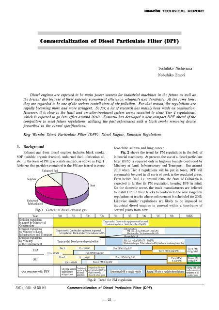
Exhaust gas from diesel engines includes black smoke,<br />
SOF (soluble organic fraction), unburned fuel, lubrication oil,<br />
etc. in the form <strong>of</strong> PM (particulate matter), as shown in Fig. 1.<br />
Airborne fine particles contained in the PM are feared to cause<br />
Sulphate<br />
Unburned<br />
lubrication oil<br />
Unburned fuel<br />
Fig. 1 Content <strong>of</strong> diesel exhaust gas<br />
Soot<br />
Year ’00 ’01 ’02 ’03 ’04 ’05 ’06 ’07 ’08 ’20XX<br />
Emission regulations<br />
in tunnel by Ministry <strong>of</strong><br />
Construction<br />
Emission regulations<br />
by Ministry <strong>of</strong> Land,<br />
Infrastructure and Transport<br />
Emission regulations<br />
by Ministry<br />
<strong>of</strong> the Environment<br />
EPA<br />
EU<br />
225 – 450kW<br />
Target model: Construction equipment in general<br />
1st regulation: Black smoke: To be reduced to 50%<br />
Target model: <strong>Diesel</strong>-powered special vehicle<br />
Tier 1<br />
Euro 1<br />
130 – 560kW<br />
75 – 130kW<br />
75 – 130kW<br />
Tier 2 PM: 0.2g/kW<br />
Euro 2 PM: 0.2g/kW<br />
bronchitic asthma and lung cancer.<br />
Fig. 2 shows the trend for PM regulations in the field <strong>of</strong><br />
industrial machinery. At present, the use <strong>of</strong> a diesel particulate<br />
filter (<strong>DPF</strong>) is required only in highway tunnels controlled by<br />
Ministry <strong>of</strong> Land, Infrastructure and Transport. But around<br />
2010 when Tier 4 regulations will be put in force, <strong>DPF</strong> will<br />
presumably be used in all sorts <strong>of</strong> work in the regulated areas.<br />
Even before 2010, i.e. around 2006, the State <strong>of</strong> California is<br />
expected to further its PM regulation, keeping <strong>DPF</strong> in mind.<br />
On the domestic scene, the truck manufacturers are believed<br />
to install <strong>DPF</strong> in their trucks to conform to the new long-term<br />
regulations <strong>of</strong> trucks whose enforcement is scheduled for 2005.<br />
Likewise similar regulations are likely to be imposed on<br />
industrial diesel engines in general within a timeframe <strong>of</strong><br />
several years from now.<br />
Target model: Construction equipment used in tunnel<br />
Content <strong>of</strong> regulation: Soot to be reduced by 80%<br />
2nd regulation:<br />
PM: 0.2 – 0.3 g/kWh (75 – 560 kW)<br />
Black smoke: To be reduced to 40%<br />
50 ppm light oil<br />
PM: 0.2 – 0.3 g/kWh (75 – 560 kW)<br />
Black emission gas: To be reduced to 40% (checked at mandatory inspection)<br />
Tier 2 PM: 0.3g/kW<br />
Euro 2 PM: 0.3g/kW<br />
Tier 3 PM: 0.13g/kW?<br />
Euro 3 PM:<br />
0.15g/kW?<br />
Tier 4 PM:<br />
0.01g/kW?<br />
Euro 4 PM:<br />
0.02g/kW?<br />
Our response with <strong>DPF</strong><br />
Checking required<br />
quality in most<br />
stringent cases<br />
Translation <strong>of</strong><br />
required quality<br />
into various<br />
applications<br />
Preparations for order<br />
receipt, sales <strong>of</strong> <strong>DPF</strong> as<br />
single commodity<br />
(tunnel & urban specs)<br />
Retr<strong>of</strong>itting <strong>DPF</strong> to special vehicle<br />
Fig. 2 Trend for PM regulation<br />
Starting <strong>DPF</strong> sales to regulation-intensified areas<br />
Starting <strong>DPF</strong> sales<br />
to all construction<br />
equipment in all<br />
regulated areas<br />
2002 q VOL. 48 NO.149<br />
<strong>Commercialization</strong> <strong>of</strong> <strong>Diesel</strong> <strong>Particulate</strong> <strong>Filter</strong> (<strong>DPF</strong>)<br />
— 23 —
2. PM reducing mechanism<br />
It is a generally practiced method for reducing soot, one<br />
<strong>of</strong> the PM constituents, that soot is arrested by filter walls that<br />
have alternately clogged pores on either side, and burnt under<br />
certain conditions. However, the temperature at which soot<br />
spontaneously ignites is 550 to 600˚C, namely pretty high<br />
temperature that is not available under the normal conditions<br />
<strong>of</strong> engine running. For this reason, a heater or a burner is<br />
used for burning soot. Another method employed is lowering<br />
the ignition temperature aided by the work <strong>of</strong> catalyst. Rather,<br />
this is the mainstream method currently, in part because<br />
heaters have not solved the reliability problem yet, and in part<br />
because handling a heater is rather complex. Catalyst coating<br />
has an effect <strong>of</strong> removing other hazardous substances such as<br />
HC and CO in addition to PM. In the case <strong>of</strong> buses and trucks<br />
in urban use, however, burning temperature cannot be reached<br />
even with catalyst, requiring a means to raise the exhaust gas<br />
temperature like a post-injection. Fortunately, burning at<br />
normal temperature is possible with the construction equipment<br />
excluding exceptional applications, since they are used under<br />
relatively heavy load.<br />
There are two ways <strong>of</strong> installing catalyst. A method that<br />
calls wide attention recently is what is termed “indirect<br />
oxidation type” developed by Johnson-Matthew. In this method,<br />
oxidation catalyst is provided at the front portion <strong>of</strong> a filter,<br />
which converts NO into NO 2. The created NO 2 burns the soot<br />
stuck to the filter through oxidation process. Merits <strong>of</strong> this<br />
method are:<br />
q Reaction from NO to NO 2 occurs at a comparatively low<br />
temperature <strong>of</strong> 250˚C, so that the reaction at a low<br />
temperature is easy.<br />
w The catalyst and the filter are separated from each other,<br />
so that no ashes pile up on the catalyst.<br />
e The catalyst is immune to the temperature <strong>of</strong> burning soot,<br />
so that its quality hardly deteriorates.<br />
On the other hand, the following demerits are enumerated.<br />
q The required parts double in number, occupying larger<br />
space.<br />
w Reaction from NO to NO 2 hardly occurs when fuel <strong>of</strong> high<br />
sulfur content is used, or when the exhaust gas<br />
temperature is high.<br />
These demerits have made it difficult to apply this method<br />
to construction equipment whose engine room is usually<br />
narrow and the exhaust gas <strong>of</strong> which shows high temperature.<br />
In this project, we opted for a method <strong>of</strong> coating catalyst direct<br />
on the filter surface, as has been the case with a ceramic<br />
exhaust muffler. Fig. 3 and Fig. 4 show the structures <strong>of</strong> both<br />
<strong>DPF</strong> systems, and Table 1 compares their performance.<br />
Exhaust<br />
Exhaust gas<br />
Plug<br />
Fig. 3 Direct oxidation type <strong>DPF</strong><br />
Pt catalyst<br />
2NO + O2 ➞ 2NO2<br />
Internal Reaction<br />
CO, HC / H2O, CO2<br />
PM / H2O, CO2<br />
Oxidation Catalyst<br />
Soot filter<br />
C + 2NO2 ➞ CO2 + 2NO<br />
C + O2 ➞ CO2<br />
Fig. 4 Indirect oxidation type <strong>DPF</strong><br />
Table 1 Comparison <strong>of</strong> <strong>DPF</strong> systems<br />
Stocked PM<br />
Porous wall<br />
Regeneration by Catalyst Regeneration by<br />
Regenerative Method Direct oxidation Indirect Heater<br />
type oxidation type (switching type)<br />
PM arresting<br />
<br />
efficiency<br />
(When fiber is in use)<br />
○ ○<br />
Burning condition<br />
Low temperature ○ ○ <br />
High temperature <br />
Impact by NOx △ <br />
Durability<br />
Broken honeycomb ○ ○ <br />
Deteriorated catalyst ○ —<br />
Impact by △<br />
sulphur content (PM increases)<br />
<br />
Complexity in control <br />
Occupied space ○ <br />
Cost<br />
Initial cost ○ <br />
Maintenance cost ○ <br />
System evolution<br />
△<br />
(Bonding with (Possible but ○<br />
DeNOx catalyst) (Possible) location restricted)<br />
Overall judgement ○ <br />
3. <strong>Komatsu</strong>’s <strong>DPF</strong> development concept<br />
<strong>Komatsu</strong> started with the manufacture <strong>of</strong> <strong>DPF</strong> (ceramic<br />
exhaust muffler) for application to tunnels managed by the then<br />
Ministry <strong>of</strong> Transport (currently Ministry <strong>of</strong> Land, Infrastructure<br />
and Transport) in 1989, and has maintained the manufacture<br />
up to the present. Now our <strong>DPF</strong> has to overcome the<br />
following problems to clear future regulations.<br />
2002 q VOL. 48 NO.149<br />
<strong>Commercialization</strong> <strong>of</strong> <strong>Diesel</strong> <strong>Particulate</strong> <strong>Filter</strong> (<strong>DPF</strong>)<br />
— 24 —
(1) PM arresting rate is rather low.<br />
The Ministry’s rule stipulates that the soot arresting rate<br />
be more than 80%, which our <strong>DPF</strong> certainly satisfies. But<br />
when PM is taken up as a whole, the arresting rate is<br />
lower than 80%, not sufficient to undisputedly conform to<br />
Tier 4.<br />
(2) Life and cleaning interval is short.<br />
So long as the application is limited to tunnel specifications,<br />
no complaint has been filed against the current life <strong>of</strong> the<br />
initial 1000 hours plus another 500 hours after reversal,<br />
1500 hours in total. But when it is installed in construction<br />
equipment in general, the maintenance interval must be<br />
drastically prolonged.<br />
(3) <strong>DPF</strong> occupies large space and is not easy to install.<br />
When the current ceramic exhaust muffler was developed<br />
for the first time, people showed little interest in the<br />
product inside the company. Moreover, there was not a<br />
sufficient variety <strong>of</strong> filter size available in those days. As<br />
a result, several pieces <strong>of</strong> <strong>DPF</strong> <strong>of</strong> the same size had to be<br />
put together and used in a set, which led to larger weight<br />
and installing space. In some instance, they were mounted<br />
on top <strong>of</strong> the engine hood.<br />
Taking those drawbacks into consideration, the following<br />
targets are set in the development <strong>of</strong> a new <strong>DPF</strong>.<br />
(1) High PM arresting rate<br />
(2) Longer cleaning interval and longer life<br />
(3) Compact and interchangeable with the current<br />
exhaust muffler<br />
4. Avenue and features<br />
If the <strong>DPF</strong> performance was limited only to the PM arresting<br />
rate, there was already a <strong>DPF</strong> developed that had attained<br />
approx. 90%. But this is a world <strong>of</strong> ambivalence. A higher<br />
arresting rate is liable to easier clogging, which in turn means<br />
a shorter life. To achieve a longer life, all that should be done<br />
is to simply increase the filter capacity, but at the expense <strong>of</strong><br />
compactness. An assignment the design engineers were faced<br />
with then was how to compromise the contradicting factors,<br />
optimizing each component. What made a great contribution<br />
to the solution <strong>of</strong> this problem was a high- density cell. Fig. 5<br />
shows a 300 cpsi cell which we adopted this time and a 100<br />
cpsi cell, as contrasted with each other. The former has an<br />
area 1.7 times as large as the latter in the same volume. That<br />
is translated into a catalyst surface area enlarged that much<br />
and lower pressure loss.<br />
The second improvement was about catalyst. A coating<br />
method different from the preceding one was applied to <strong>DPF</strong><br />
for the first time. The new method contributed to improving<br />
the reaction and enhancing durability <strong>of</strong> <strong>DPF</strong>. While<br />
considering a unique characteristic in the application <strong>of</strong><br />
construction equipment that they are commonly used under<br />
the heavy load condition, we succeeded in drastically reducing<br />
the consumption <strong>of</strong> precious metal used for catalyst. Precious<br />
metal accounts for the most part <strong>of</strong> the catalyst production cost,<br />
therefore, its reduced consumption largely contributed to the<br />
overall cost reduction efforts.<br />
The third improvement was to assure even gas flow at<br />
the inlet. Unlike buses and trucks, an exhaust muffler is<br />
housed in the engine room in the case <strong>of</strong> construction<br />
equipment. In this regard, gas flow-in and flow-out in the axial<br />
direction is desirable from the standpoint <strong>of</strong> even gas flow.<br />
Construction equipment cannot adopt this gas flow pattern due<br />
to the above reason. Instead, a pattern <strong>of</strong> gas flow-in and flowout<br />
in the radial direction is adopted in most cases <strong>of</strong> models.<br />
It is understood from Fig. 6 showing a rough sketch <strong>of</strong> an<br />
exhaust muffler that gas at the inlet is deflected in the opposite<br />
direction to flow-in and naturally causes soot to pile up. In<br />
that case, a large heat distribution occurs at the time <strong>of</strong> burning<br />
and the muffler is highly likely to fail.<br />
Fig. 6 Distribution <strong>of</strong> gas flow at inlet (conventional type)<br />
We carried out a CFD analysis to correct the drawback as<br />
discussed above, and Fig. 7 shows an improved exhaust<br />
muffler that is resulted from the analysis. It is provided with<br />
a perforated cylindrical metal sheet and a resistance plate at<br />
the inlet, which are supposed to optimize magnitude and<br />
location <strong>of</strong> resistance in the gas flow to assure even gas flow.<br />
100 cpsi 300 cpsi<br />
Fig. 5 Comparison <strong>of</strong> new and old filters<br />
Fig. 7 Distribution <strong>of</strong> gas flow at inlet (improved type)<br />
2002 q VOL. 48 NO.149<br />
<strong>Commercialization</strong> <strong>of</strong> <strong>Diesel</strong> <strong>Particulate</strong> <strong>Filter</strong> (<strong>DPF</strong>)<br />
— 25 —
5. Determining filter size<br />
A factor determining the filter size is its cleaning interval<br />
and the life up until the next replacement. In addition, it is<br />
necessary to pay attention to noise abatement, as the filter <strong>of</strong>ten<br />
doubles as an exhaust muffler.<br />
The filter life is commonly determined as a period until<br />
the specified exhaust gas pressure is reached. This exhaust<br />
gas pressure is defined as a limit up to which no negative<br />
impact is imposed on the engine performance and durability,<br />
or as a limit up to which <strong>DPF</strong> does not fail at the time <strong>of</strong> soot<br />
burning. The biggest factor <strong>of</strong> pushing up the exhaust gas<br />
pressure is a balance between the amount <strong>of</strong> generated soot<br />
and the amount <strong>of</strong> combustible soot. Even so, it is also<br />
necessary to make allowances for the accumulated ash, catalyst<br />
deterioration with age, the increase <strong>of</strong> soot and exhaust gas<br />
temperature due to the rising exhaust gas pressure, etc.<br />
5.1 Forecast <strong>of</strong> generated soot amount<br />
Working modes <strong>of</strong> construction equipment may be more<br />
or less safely sorted out into some patterns. Hence the first<br />
assignment is to strike a balance between the generated amount<br />
<strong>of</strong> soot and the regenerated amount after combustion in each<br />
pattern. Let’s take V shape work by a front-end loader for<br />
example. The operation pattern is shown in Fig. 8.<br />
Engine revolution<br />
each other. Hence we trust that there is no problem with the<br />
use <strong>of</strong> this simple calculation method. Now Bosch smoke<br />
number <strong>of</strong> the exhaust gas is a function <strong>of</strong> the exhaust gas<br />
pressure. An experiment discloses that it changes linearly. In<br />
other words, there is a tendency that the soot concentration<br />
rises and the amount <strong>of</strong> soot piled on the <strong>DPF</strong> increases, as<br />
<strong>DPF</strong> clogging continues.<br />
5.2 Estimate <strong>of</strong> burned soot amount<br />
The soot burning amount can be obtained using the<br />
Arrhenius equation with a soot combustible amount per unit<br />
area <strong>of</strong> the <strong>DPF</strong> surface as a function <strong>of</strong> temperature.<br />
Fig. 9 shows the results <strong>of</strong> this calculation. Since an<br />
operation cycle time <strong>of</strong> construction equipment is usually<br />
comparatively short, the above calculation is made based on a<br />
premise that the catalyst temperature remains constant during<br />
one operation cycle time. Meanwhile, the exhaust gas<br />
temperature is a function <strong>of</strong> the exhaust gas pressure, and rises<br />
as <strong>DPF</strong> clogging goes on. That phenomenon works to increase<br />
the amount <strong>of</strong> burned soot.<br />
LN (Soot processing amount)<br />
Time<br />
Fig. 8 Front-end loader work cycle time pattern<br />
For the purpose <strong>of</strong> checking the generated amount <strong>of</strong> soot,<br />
it suffices to bench-test an engine, simulating this pattern and<br />
take measurement by means <strong>of</strong> a full dilution tunnel. But there<br />
is a possibility that <strong>DPF</strong> is retr<strong>of</strong>itted to various kinds <strong>of</strong><br />
construction equipment, therefore, we worked out a simpler<br />
calculation formula.<br />
For calculating a soot amount generated under the normal<br />
and constant operation <strong>of</strong> an engine, there is a MIRA formula<br />
that makes a calculation based on Bosch smoke number.<br />
S 0.982 BSU 10^ (0.1276 BSU 1.66)<br />
A point at issue here is an estimate at a transitional period.<br />
An acceleration time has been classified into the initial<br />
acceleration time when an engine generates a large amount <strong>of</strong><br />
soot, and the subsequent acceleration time when the soot<br />
amount is limited. For the initial acceleration time, a measured<br />
Bosch smoke number value was converted using the above<br />
formula. For the subsequent acceleration time, a Bosch smoke<br />
number value at the peak under the normal, constant operation<br />
<strong>of</strong> the engine was converted again using the above formula.<br />
The initial acceleration time was worked out by an opacity<br />
measurement. When the calculated value was compared with<br />
the value obtained from an experiment by means <strong>of</strong> a full<br />
dilution tunnel, there was comparatively high compatibility with<br />
1/(<strong>DPF</strong> inlet temperature) (1/K)<br />
Fig. 9 Catalyst processing capability<br />
5.3 Estimate <strong>of</strong> pressure loss<br />
The following are included in the category <strong>of</strong> <strong>DPF</strong><br />
pressure loss.<br />
(1) Loss due to abrupt expansion or bending <strong>of</strong> piping at<br />
the <strong>DPF</strong> inlet and outlet<br />
(2) Airflow resistance in a new filter<br />
(3) Airflow resistance due to accumulated soot and ashes<br />
(1) and (2) factors remain invariable in value, while factor<br />
(3) changes with age. We first obtained a pressure loss<br />
coefficient <strong>of</strong> the soot unit amount per unit area from<br />
increments <strong>of</strong> the piled-up soot and pressure loss. Then we<br />
assumed that the pressure loss coefficient was in proportion<br />
to the soot amount and pressure loss was in proportion to the<br />
velocity head.<br />
5.4 Deterioration <strong>of</strong> catalyst<br />
Causes for the catalyst activation to deteriorate are:<br />
(1) Deterioration in activation <strong>of</strong> the catalyst itself<br />
(2) Reduction <strong>of</strong> reaction surface due to ashes piled up<br />
on the catalyst surface<br />
The type <strong>of</strong> catalyst that is coated on a filter as in the new<br />
<strong>DPF</strong> is termed “direct soot oxidizing catalyst”, and was feared<br />
2002 q VOL. 48 NO.149<br />
<strong>Commercialization</strong> <strong>of</strong> <strong>Diesel</strong> <strong>Particulate</strong> <strong>Filter</strong> (<strong>DPF</strong>)<br />
— 26 —
to dissipate through evaporation. But the fact was that a<br />
reaction from NO to NO 2 was going on at the same time, and<br />
no marked deterioration was noticed. On the other hand,<br />
phenomenon (2) above was believed to be steadily taking place,<br />
considering the fact that the balance temperature was rising.<br />
Hence metallic contents in the lubrication oil as well as<br />
sulphuric content in the fuel should be deemed an important<br />
factor. We implemented the calculation on the assumption that<br />
the extent <strong>of</strong> deterioration was in proportion to the accumulated<br />
ash amount per surface unit area, and the accumulated ash<br />
amount was in proportion to the sulphur content in the fuel<br />
and fuel consumption amount.<br />
A single filter is enough for the <strong>Komatsu</strong>’s line <strong>of</strong> engines<br />
up to 6D140, and a lineup <strong>of</strong> the filters with almost complete<br />
interchangeability with the current exhaust mufflers has been<br />
prepared. Fig. 12 shows the structure and Fig. 13 shows how<br />
the new filter is installed on an actual engine.<br />
5.5 Results <strong>of</strong> calculation for simulation<br />
Shown in Fig. 10 are a comparison between the<br />
calculation value and the experimental value regarding the<br />
conventional <strong>DPF</strong> <strong>of</strong> 2 7.5 7" with 100 cpsi and the<br />
calculation value <strong>of</strong> the newly developed <strong>DPF</strong> <strong>of</strong> 12" 9"<br />
with 300 cpsi.<br />
Exhaust gas pressure (mmHg)<br />
Experimental value – Current <strong>DPF</strong><br />
Calculated value – Current <strong>DPF</strong><br />
Calculated value – New <strong>DPF</strong><br />
Fig. 12 Cross-sectional view <strong>of</strong> <strong>DPF</strong> for PC200 excavator engine<br />
Operation cycle time (Hr.)<br />
Fig. 10 Result <strong>of</strong> life estimate<br />
Both the calculated and experimental values <strong>of</strong> the current<br />
<strong>DPF</strong> show high concurrence except for the last portion. The<br />
current 100 cpsi <strong>DPF</strong> shows gradual accumulation <strong>of</strong> soot from<br />
the initial stage and eventually reaches the pressure limit. With<br />
the newly developed <strong>DPF</strong>, its soot disposal capability exceeds<br />
the soot pileup amount for a considerable long time and<br />
thereafter the curve rises rather sharply.<br />
We carried out this calculation for each major application<br />
<strong>of</strong> the engines and determined the optimum <strong>DPF</strong> size. The<br />
calculation results are shown in Table 2.<br />
Table 2 <strong>DPF</strong> lineup<br />
Notation Engine Volume Muffler Size New <strong>DPF</strong> (300cpsi)<br />
(r) (mm) <strong>Filter</strong> Size Body Size<br />
KCM-1 3D84 1.5 150 380 5.66” 5” 156 375<br />
KCM-1 4D84 2.0 170 465 5.66” 5” 156 450<br />
KCM-3 4D95 3.3 220 450 7.5” 7” 203 450<br />
KCM-4 4D102 3.9 220 600 9” 7” 241 450<br />
KCM-5 6D102 5.9 280 525 12” 7” 318 525<br />
KCM-6 6D114 7.2 280 675 12” 9” 318 700<br />
KCM-7 6D125 11.0 280 800 12” 12” 318 700<br />
KCM-8 6D140 15.2 340 800 12” 14” 318 775<br />
KCM-10 6D170 23.2 460 700 2 12” 12” 318 697 800<br />
Fig. 13 <strong>DPF</strong> mounted on PC200 excavator engine<br />
2002 q VOL. 48 NO.149<br />
<strong>Commercialization</strong> <strong>of</strong> <strong>Diesel</strong> <strong>Particulate</strong> <strong>Filter</strong> (<strong>DPF</strong>)<br />
— 27 —
6. Test results<br />
Fig. 14 shows the effect <strong>of</strong> emission reduction. The newly<br />
developed <strong>DPF</strong> demonstrates excellence over the conventional<br />
<strong>DPF</strong> across all the items <strong>of</strong> comparison.<br />
Fig. 15 deals with noise characteristics. A damping<br />
characteristic nearly equal to that <strong>of</strong> the conventional exhaust<br />
muffler can be obtained from the new <strong>DPF</strong>. Hence it can well<br />
substitute the conventional exhaust muffler.<br />
Conventional <strong>DPF</strong><br />
Newly developed <strong>DPF</strong><br />
7. Conclusion<br />
We are now confident that utilizing the past experiences<br />
with tunnel specifications, we could successfully develop a<br />
compact <strong>DPF</strong> with higher efficiency and longer life plus nearly<br />
full interchangeability with the current exhaust mufflers. The<br />
new <strong>DPF</strong> will be able to conform to emission regulations in<br />
the near future. As the next step, we will press ahead with<br />
further cost reduction so that the cost will not be a stumbling<br />
block for the sales promotion efforts. It is our hope to see it<br />
will be widely accepted in the world markets now that it has<br />
been proven very effective to protecting the environment.<br />
Emission reduction ratio<br />
CO THC PM<br />
Fig. 14 Emission reduction characteristic<br />
FULL LOAD<br />
EXHAUST NOISE<br />
<strong>DPF</strong><br />
Exhaust muffler<br />
800 1200 1600 2000 2400 2800<br />
ENGINE SPEED (rpm)<br />
Introduction <strong>of</strong> the writers<br />
Toshihiko Nishiyama<br />
Entered <strong>Komatsu</strong> in 1969.<br />
Currently working in Component Research<br />
& Development Group, IPA, Ltd.<br />
NO LOAD<br />
EXHAUST NOISE<br />
Exhaust muffler<br />
<strong>DPF</strong><br />
Nobuhiko Emori<br />
Entered <strong>Komatsu</strong> in 1983.<br />
Currently working in Component Research<br />
& Development Group, IPA, Ltd.<br />
800 1200 1600 2000 2400 2800<br />
ENGINE SPEED (rpm)<br />
Fig. 15 Noise characteristic<br />
[A few words from the writers]<br />
Our <strong>DPF</strong> is a product closely connected with the protection <strong>of</strong><br />
the global environment. Keeping the fact in mind, we have strived<br />
to always go even a step ahead <strong>of</strong> the competitors. Hopefully the<br />
product will also boost a good image <strong>of</strong> our company in the society.<br />
The vital parts <strong>of</strong> <strong>DPF</strong>, i.e. filters and catalyst, are manufactured<br />
based on our suppliers’ technology. For this reason, it was rather<br />
difficult to characterize the new <strong>DPF</strong>. It happened, however, that<br />
the two suppliers started with the development <strong>of</strong> new products<br />
around the same time and <strong>Komatsu</strong> was the first to utilize them.<br />
We could fully enjoy the good luck.<br />
2002 q VOL. 48 NO.149<br />
<strong>Commercialization</strong> <strong>of</strong> <strong>Diesel</strong> <strong>Particulate</strong> <strong>Filter</strong> (<strong>DPF</strong>)<br />
— 28 —