Development of Assembly Work Control System - Komatsu
Development of Assembly Work Control System - Komatsu
Development of Assembly Work Control System - Komatsu

Create successful ePaper yourself
Turn your PDF publications into a flip-book with our unique Google optimized e-Paper software.
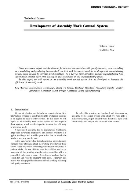
Technical Papers<br />
<strong>Development</strong> <strong>of</strong> <strong>Assembly</strong> <strong>Work</strong> <strong>Control</strong> <strong>System</strong><br />
Takashi Ueno<br />
Yoshihiro Yao<br />
Since we cannot expect that the demand for construction machines will greatly increase, we are working<br />
on a developing and producing process which can feed back the market needs to the design and manufacturing<br />
sections more quickly to increase the throughput. As a part <strong>of</strong> these activities, various manufacturing field<br />
information systems have been developed and introduced in the manufacturing fields.<br />
In this paper, we will report on an assembly work control system that we developed to increase the<br />
efficiency <strong>of</strong> assembly work.<br />
Key Words: Information Technology, Build To Order, <strong>Work</strong>ing Standard Procedure Sheets, Quality<br />
Assurance, Computer Aided Design, Computer Aided Manufacturing<br />
1. Introduction<br />
We are developing and introducing manufacturing field<br />
information systems to construct flexible production systems<br />
to be applied to build-to-order service. In this paper, we will<br />
report on an assembly work control system as an example <strong>of</strong><br />
those systems which we developed to increase the efficiency<br />
<strong>of</strong> assembly work.<br />
A large-sized assembly line to manufacture bulldozers,<br />
large-sized hydraulic excavators, and mobile crushers is a<br />
typical multi-type and small-lot production line on which the<br />
products are sent one by one.<br />
In the past, workers had to find applicable sheets in many<br />
standard work tables and check the working procedure in those<br />
sheets while they were assembling construction machines <strong>of</strong><br />
various kinds. It was difficult even for a skilled worker to<br />
memorize all the working procedures for a machine which is<br />
assembled only once a year. Accordingly, workers had to<br />
search for and read the standard work table. Naturally, this<br />
matter was a large problem in terms <strong>of</strong> both working efficiency<br />
and quality assurance.<br />
To solve this problem, we developed and introduced an<br />
assembly work control system with which we were able to<br />
make work plans, output detailed work directions, input work<br />
result easily, and analyze the collected work results.<br />
2001 w VOL. 47 NO.148<br />
<strong>Development</strong> <strong>of</strong> <strong>Assembly</strong> <strong>Work</strong> <strong>Control</strong> <strong>System</strong><br />
— 3 —
2. Features <strong>of</strong> system<br />
For high throughput by the build-to-order service, the<br />
system must have function <strong>of</strong> efficiently making personnel<br />
arrangement plans on a good line balance and eliminating<br />
useless work to increase productivity, and assure the quality<br />
traceability.<br />
In response to these demands, we developed the system<br />
having the following features.<br />
(1) Reading production plan and making work plan<br />
This system reads the production plan from the factory<br />
production control system every day and makes a personnel<br />
arrangement plan, counting in the line balance. With this<br />
function, we can make a work plan containing no process loss<br />
and can form the process easily.<br />
(2) Display <strong>of</strong> work direction easy to understand and<br />
information necessary to the field<br />
Products <strong>of</strong> various types flow on the line. It is difficult<br />
even for a skilled worker to memorize all the working<br />
procedures for a product which has special specifications and<br />
which is assembled only once a year.<br />
Then, this system gives easily-understood work directions<br />
using images and voice. Since the correct directions on the<br />
assembly procedure and inspection are given, we can assure<br />
quality perfectly.<br />
Furthermore, this system can be used with other manufacturing<br />
field information systems to reduce useless work<br />
processes by displaying information on inspection and missing<br />
<strong>of</strong> parts.<br />
(3) Easy input <strong>of</strong> work results<br />
Understanding the work results in real time is essential<br />
naturally for giving detailed work directions according to the<br />
current condition <strong>of</strong> the manufacturing field where unexpected<br />
problems can occur.<br />
To meet this requirement, we designed and built a system<br />
with which workers can input the start and completion <strong>of</strong> each<br />
job.<br />
(4) Reflection <strong>of</strong> measures to solve problems quickly in<br />
work directions<br />
If problem such as delay <strong>of</strong> the work occurs, we can<br />
change the arrangement <strong>of</strong> the workers, work order, etc.<br />
quickly in the work directions.<br />
(5) Analysis <strong>of</strong> collected work results<br />
We can constantly make improvements by analyzing the<br />
collected data <strong>of</strong> past work, extracting points to be improved<br />
such as useless work, and correcting standard work.<br />
(6) Wide choice <strong>of</strong> means to input and output<br />
We can choose proper means to input and output by<br />
making program modules for each function and applying those<br />
modules to various workplaces where different functions are<br />
required. (Fig. 1)<br />
In addition, we can minimize the cost <strong>of</strong> development <strong>of</strong><br />
additional functions and modification <strong>of</strong> the existing functions.<br />
Means to<br />
output work directions<br />
Voice<br />
Display<br />
PDA<br />
.<br />
Physical distribution<br />
control system<br />
Data <strong>of</strong><br />
missing parts<br />
<strong>Assembly</strong> work<br />
control system<br />
Means to<br />
input work results<br />
Voice<br />
Fig. 1 Modules <strong>of</strong> application s<strong>of</strong>tware<br />
Production<br />
order<br />
Scheduling system<br />
<strong>Work</strong> results<br />
Process<br />
design data<br />
<strong>Work</strong> plan<br />
<strong>Assembly</strong> work<br />
control system<br />
PHS (Push buttons)<br />
Keyboard/Mouse<br />
PDA<br />
Impact wrench<br />
controller<br />
Wireless digital<br />
slide calipers<br />
Wireless torque<br />
set wrench<br />
.<br />
3. <strong>System</strong> configuration<br />
The following is the configuration <strong>of</strong> the system we<br />
constructed. (Fig. 2)<br />
Fig. 2 Rough system configuration<br />
Inspection<br />
standard<br />
Quality<br />
control system<br />
Inspection<br />
result<br />
(1) Scheduling system<br />
If production order (date <strong>of</strong> production, production order,<br />
models, serial number, and specification information) and<br />
process design data (models, specification information,<br />
processes, man-hours, and worker information) are input, this<br />
system outputs the model, workers, working time, etc. for each<br />
process, considering the conditions <strong>of</strong> the workers.<br />
(2) <strong>Assembly</strong> work control system<br />
This system gives detailed work directions and collects<br />
work results according to the work plan and process design<br />
data (models, specification information, processes, work order,<br />
contents <strong>of</strong> work, standard working hours, images, etc.)<br />
Each worker works according to the given directions and<br />
inputs the start and completion <strong>of</strong> each job. The work results<br />
are reflected in the scheduling system.<br />
(3) Quality control system I/F<br />
By cooperating with the quality control system which<br />
controls the inspection information on the parts and machine<br />
bodies, the assembly work control system can control the<br />
quality data at one place to realize perfect quality assurance.<br />
The inspection standard received from the quality control<br />
system controlled by the inspection section is registered as<br />
the contents <strong>of</strong> the work directions in the process design data.<br />
The inspection results collected by the workers are transferred<br />
through this system.<br />
2001 w VOL. 47 NO.148<br />
<strong>Development</strong> <strong>of</strong> <strong>Assembly</strong> <strong>Work</strong> <strong>Control</strong> <strong>System</strong><br />
— 4 —
(4) Physical distribution control system I/F<br />
By cooperating with the physical distribution system which<br />
controls the information on delivery and transportation <strong>of</strong> the<br />
parts, the assembly work control system can display missing<br />
parts for each process. (Since the physical distribution control<br />
system is under modification, it is not yet connected.)<br />
Fig. 3 shows a typical flow <strong>of</strong> data in the system and Fig. 4<br />
shows a typical system hardware configuration.<br />
Physical distribution control<br />
system server<br />
Missing parts file<br />
Factory production<br />
control system<br />
Production<br />
order file<br />
Transmission <strong>of</strong><br />
missing parts data<br />
<strong>Assembly</strong> work control<br />
system server<br />
Make plan and<br />
contents <strong>of</strong> work<br />
Scheduler/Contents editing manager<br />
terminal<br />
<strong>Work</strong> control table<br />
(<strong>Work</strong> directions DB)<br />
Transmission <strong>of</strong><br />
work direction data<br />
<strong>Work</strong> directions and<br />
results collecting terminal<br />
<strong>Work</strong> directions file<br />
Quality control system<br />
server<br />
Inspection<br />
standard DB<br />
Transmission <strong>of</strong><br />
inspection standard<br />
Process design table<br />
Transmission <strong>of</strong><br />
work results data<br />
<strong>Work</strong> results file<br />
<strong>Work</strong> results DB<br />
Transmission <strong>of</strong><br />
inspection results<br />
<strong>Work</strong> control table<br />
(<strong>Work</strong> results DB)<br />
Impact wrench<br />
controller<br />
Tightening results file<br />
Fig. 3 Flow <strong>of</strong> system data<br />
Voice recognition and<br />
response system terminal<br />
Factory production control system<br />
(BaaN/Host)<br />
Quality control<br />
system server<br />
Physical distribution<br />
system server<br />
Router<br />
Network in factory<br />
Manufacturing fields<br />
network<br />
Scheduler/Contents editing<br />
manager terminal<br />
<strong>Work</strong> directions<br />
and results<br />
collecting terminal<br />
<strong>Work</strong> directions<br />
and results<br />
collecting terminal<br />
<strong>Work</strong> directions<br />
and results<br />
collecting terminal<br />
. . .<br />
<strong>Assembly</strong> work<br />
control system server<br />
Voice recognition<br />
and response<br />
system terminal<br />
Private<br />
branch exchange<br />
. . .<br />
PHS<br />
PHS<br />
PHS<br />
Fig. 4 Hardware configuration <strong>of</strong> system<br />
2001 w VOL. 47 NO.148<br />
<strong>Development</strong> <strong>of</strong> <strong>Assembly</strong> <strong>Work</strong> <strong>Control</strong> <strong>System</strong><br />
— 5 —
4. Functions <strong>of</strong> assembly work control system<br />
We will describe the main functions and features <strong>of</strong> the<br />
assembly work control system below.<br />
(1) <strong>Work</strong> directions and results collecting terminal<br />
(a) Main functions <strong>of</strong> giving work directions<br />
<strong>Work</strong> directions are made on the basis <strong>of</strong> the production<br />
order and process design data, then detailed work directions<br />
are given by voice and images.<br />
The contents <strong>of</strong> the work directions (models, specification<br />
information, processes, work order, contents <strong>of</strong> work, standard<br />
working hours, images, wording, etc.) are registered as process<br />
design data by model and specification <strong>of</strong> the products.<br />
Information on past trouble is fed back to the work directions<br />
quickly to improve quality.<br />
The image data, which are a part <strong>of</strong> the contents <strong>of</strong> the<br />
work directions, must contain the information on each part<br />
number and important points <strong>of</strong> the quality and must be made<br />
so easy to understand that even an unskilled worker can work<br />
by himself (herself) if he (she) sees them. Accordingly, those<br />
data are used as tools to increase the number <strong>of</strong> workers who<br />
have multiple skills.<br />
Much <strong>of</strong> the image data used currently are based on the<br />
photos taken with digital cameras. If a model is developed by<br />
means <strong>of</strong> 3-dimensional CAD, however, we will use the 3-<br />
dimensional data effectively instead <strong>of</strong> the photos.<br />
Fig. 5 shows an example <strong>of</strong> the main screen <strong>of</strong> the work<br />
directions.<br />
This example is the work directions screen displayed 4<br />
seconds after the worker “Hamamura” started the job<br />
*2 “Permanent tightening <strong>of</strong> both mounting bolts <strong>of</strong> P/L” in<br />
the major work division <strong>of</strong> *1 “Assistance in mounting P/L” in<br />
the “5th process” <strong>of</strong> the products <strong>of</strong> “D155A-3”, the standard<br />
working time <strong>of</strong> which is “2 minutes 10 seconds”. At the same<br />
time when the worker starts the above job, the voice work<br />
direction for “Permanent tightening <strong>of</strong> both mounting bolts <strong>of</strong><br />
P/L” is given, too.<br />
Voice output from the work directions and results<br />
collecting terminal and the display connected to that terminal<br />
are prepared as means to give work directions.<br />
If a wireless voice transmitter-receiver or a PHS is used,<br />
the voice directions can be received by wireless at a place<br />
remote from the work directions and results collecting terminal.<br />
In addition to a desktop personal computer used as the<br />
normal terminal, a PDA, notebook personal computer, wireless<br />
display personal computer, large-sized display, etc. can be<br />
combined and used according to the requirements in each<br />
workplace.<br />
Photo 1 shows examples <strong>of</strong> the work directions and<br />
results collecting terminal and the voice work directions and<br />
result collecting device.<br />
Photo 1 Large-sized display (left), headset and PHS (right)<br />
*1<br />
Hamamura<br />
Tools to be used<br />
KW38<br />
Impact wrench<br />
36mm BOX<br />
*2<br />
After tightening both mounting bolts<br />
<strong>of</strong> P/L permanently<br />
Place impact wrench<br />
temporarily<br />
Fig. 5 Main screen <strong>of</strong> work directions<br />
2001 w VOL. 47 NO.148<br />
<strong>Development</strong> <strong>of</strong> <strong>Assembly</strong> <strong>Work</strong> <strong>Control</strong> <strong>System</strong><br />
— 6 —
(b) Sub-functions <strong>of</strong> giving work directions<br />
When a worker uses an impact wrench controller to<br />
tighten a bolt, the sub-screen shown in Fig. 6 is displayed.<br />
At the time for this work, the standard values for each<br />
model and part registered in the process design data (lower<br />
limit and upper limit <strong>of</strong> the tightening torque, number <strong>of</strong> impact,<br />
etc.) are set to the impact wrench controller connected to the<br />
work directions and results collecting terminal, and the<br />
Fig. 6 <strong>Work</strong> direction sub-screen<br />
controller judges the result <strong>of</strong> each tightening impact. If the<br />
result is judged bad, the worker must loosen the bolt and<br />
tighten it again similarly or must tighten it by hand (without<br />
using the impact wrench controller) to leave only the normal<br />
tightening result.<br />
Since the bolt to be tightened next is shown on the screen,<br />
the worker can tighten all bolts in the same order every time.<br />
Accordingly, the quality is kept consistent.<br />
(c) Main functions <strong>of</strong> collecting work results<br />
The worker can input the start and completion <strong>of</strong> each<br />
job with a remote controller, a voice device based on a voice<br />
recognition and response system, or the keyboard and mouse<br />
<strong>of</strong> the work directions and result collecting terminal.<br />
If the worker uses a headset (Photo 1) to collect the<br />
results by voice with a PHS, he (she) can collect the results<br />
with his (her) hands free. The worker can select work plans<br />
and collect the basic work results by using several words such<br />
as “Finish”, “Interrupt”, etc. which are set in the voice<br />
recognition and response system and pressing the push buttons<br />
<strong>of</strong> the PHS.<br />
Fig. 7 shows a rough flow <strong>of</strong> jobs <strong>of</strong> giving voice work<br />
directions and collecting work results through the PHS.<br />
Start<br />
“Input job number”<br />
Connection <strong>of</strong> line<br />
200<br />
“ ”<br />
: Words given by voice recognition and<br />
response system<br />
“ ” : Words given by worker<br />
Example) 12345<br />
Input <strong>of</strong> job<br />
number push buttons<br />
: Push button pressed by worker<br />
Example) “Mr. Tanaka, you are at the 2nd process for<br />
model D155AX-5, aren’t you? Is this plan OK?”<br />
Is input<br />
checked?<br />
Yes<br />
1<br />
Input by voice/<br />
push button<br />
No<br />
“Finished/OK”<br />
Example)<br />
“Mount engine, 5 minutes 30 seconds”<br />
<strong>Work</strong> directions<br />
No<br />
Input by voice<br />
/push button<br />
1 “Finished/OK” 3 “Interrupt” “Screen” “Try once more”<br />
Input by voice<br />
/push button<br />
Input by voice Input by voice<br />
“Interrupted”<br />
“Change screen”<br />
Is there no next<br />
work?<br />
“Press restart button or<br />
input failure code by PHS”<br />
“Thank you.<br />
<strong>Work</strong> is finished.”<br />
Yes<br />
Breaking <strong>of</strong> line<br />
Input by<br />
push button<br />
1 2 3 0<br />
End<br />
Registration <strong>of</strong> reason<br />
for abnormality<br />
Cancellation <strong>of</strong> registration <strong>of</strong><br />
reason for abnormality<br />
Fig. 7 Rough flow <strong>of</strong> jobs to give work directions and collect work results by voice<br />
2001 w VOL. 47 NO.148<br />
<strong>Development</strong> <strong>of</strong> <strong>Assembly</strong> <strong>Work</strong> <strong>Control</strong> <strong>System</strong><br />
— 7 —
(d) Sub-functions <strong>of</strong> collecting work results<br />
For jobs concerned with inspection in the work directions<br />
(input <strong>of</strong> visual inspection result, input <strong>of</strong> stamp number, and<br />
input and judgment <strong>of</strong> measured values), the sub-screen shown<br />
in Fig. 8 is displayed to input the work results.<br />
(b) Function <strong>of</strong> displaying work results<br />
The Gantt chart <strong>of</strong> the work results by worker is displayed.<br />
The manager analyzes the data, extracts and solves<br />
problems, and corrects the process design data repeatedly with<br />
this function to continue improvement.<br />
Fig. 10 shows a sample <strong>of</strong> the work results screen.<br />
Fig. 8 Sub-screen for collecting work results<br />
(2) Server<br />
(a) Function <strong>of</strong> displaying operating condition table <strong>of</strong> line<br />
The server displays the real-time operating condition table<br />
<strong>of</strong> the client connected to this system (processes, models, serial<br />
numbers, workers’ names, and progress). The progress <strong>of</strong> each<br />
worker can be determined by coloring the delay and lead from<br />
the standard working time set for each work item.<br />
The manager can grasp the progress in the field at a<br />
glance from the <strong>of</strong>fice.<br />
Fig. 9 shows a sample screen <strong>of</strong> the line monitor.<br />
Fig. 10 <strong>Work</strong> results screen.<br />
5. Examples <strong>of</strong> application<br />
The following are examples <strong>of</strong> application <strong>of</strong> the above<br />
system.<br />
(1) <strong>Assembly</strong> line for bodies <strong>of</strong> large-sized construction<br />
machines<br />
On this line where the above system was introduced for<br />
the first time, work directions are given by a large-sized display.<br />
In addition, the work directions are also given and the work<br />
results are collected through a voice recognition and response<br />
system and PHS. <strong>Work</strong>ers can perform these operations with<br />
their hands free.<br />
(2) <strong>Assembly</strong> line for parts <strong>of</strong> large-sized construction<br />
machines<br />
On this line where the main work is to tighten bolts with<br />
impact wrench controllers, ordinary personal computers are<br />
used to give work directions and collect the results.<br />
We are now introducing the above system to the subassembly<br />
line for the bodies <strong>of</strong> large-sized construction<br />
machines, assembly line for medium-sized engines, and<br />
assembly line for custom machines.<br />
Fig. 9 Screen <strong>of</strong> the line monitor<br />
2001 w VOL. 47 NO.148<br />
<strong>Development</strong> <strong>of</strong> <strong>Assembly</strong> <strong>Work</strong> <strong>Control</strong> <strong>System</strong><br />
— 8 —
6. Conclusion<br />
In this paper, we introduced the system used mainly for<br />
supporting the assembly work by giving detailed work<br />
directions by voice and images and collecting the work results<br />
by voice and remote control to improve the quality and<br />
productivity.<br />
In the future, we will examine and develop tools to reflect<br />
frequent design changes in the work directions quickly and<br />
systems to efficiently use the 3-dimensional design data for<br />
the work directions in cooperation with the CAD/CAM systems.<br />
Introduction <strong>of</strong> the writers<br />
Takashi Ueno<br />
Entered <strong>Komatsu</strong> in 1996.<br />
Currently working in Plant Coordination<br />
Dept., Osaka Plant, Production Div.<br />
Yoshihiro Yao<br />
Entered <strong>Komatsu</strong> in 1985.<br />
Currently working in Plant Coordination<br />
Dept., Osaka Plant, Production Div.<br />
[A few words from the writers]<br />
If the functions <strong>of</strong> this system are improved and utilized fully,<br />
cooperating even more with other systems, the culture in the<br />
conventional manufacturing fields can be changed. We intend to<br />
develop production systems mainly for the manufacturing fields to<br />
make up flexible factories directly coupled with the market for<br />
build-to-order service.<br />
2001 w VOL. 47 NO.148<br />
<strong>Development</strong> <strong>of</strong> <strong>Assembly</strong> <strong>Work</strong> <strong>Control</strong> <strong>System</strong><br />
— 9 —