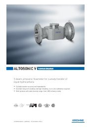
ALTOSONIC V12
ALTOSONIC V12
ALTOSONIC V12
You also want an ePaper? Increase the reach of your titles
YUMPU automatically turns print PDFs into web optimized ePapers that Google loves.
Now with KROHNE Care<br />
TM<br />
<strong>ALTOSONIC</strong> <strong>V12</strong><br />
12 chord ultrasonic gas flowmeter for custody transfer<br />
Setting a new standard with its OIML R137 class 0.5 approval<br />
Minimal straight inlet requirements due to excellent swirl immunity<br />
The first meter with a dedicated ultrasonic path for diagnostics<br />
Web-based diagnostics expert system to interrogate the meter’s health
Uncertainty<br />
from calibration<br />
Uncertainty due to<br />
installation effects<br />
Total uncertainty<br />
after installation<br />
Uncertainty due<br />
to contamination<br />
More than just the tip of the iceberg<br />
Like an iceberg, the main dangers to good metering<br />
lie below the surface. Calibrations are done under<br />
ideal conditions which are different from the actual<br />
conditions in the field. After installation in the field the<br />
measurement accuracy will be affected by installation<br />
effects and contamination inside the meter; both<br />
aspects that are not seen during a calibration.<br />
<strong>ALTOSONIC</strong> <strong>V12</strong> is designed to be virtually<br />
TM<br />
immune to installation effects. KROHNE<br />
Care’s web-based diagnostics continuously<br />
monitor over a 1200 values to inspect the performance<br />
of the meter, alerting the operator long before<br />
contamination inside can cause a significant<br />
measurement error.
The only relevant accuracy<br />
is accuracy in the field<br />
The benefits of OIML R137 Class 0.5<br />
Comparison of overall meter uncertainty<br />
0.40%<br />
Calibration<br />
Installation<br />
During a high-pressure calibration ultrasonic gas flowmeters will typically<br />
achieve ±0.2% accuracy, or even ±0.1% after linearization of the measurement<br />
result. This does however not mean that your accuracy in the field will stay at<br />
±0.1%.<br />
0.30%<br />
0.20%<br />
0.10%<br />
Lowest overall<br />
uncertainty<br />
Additional uncertainty due to installation effect<br />
0.00%<br />
OIML R 137<br />
Class 1<br />
AGA 9<br />
ISO 17089<br />
OIML R 137<br />
Class 0.5<br />
Once a flowmeter is installed in the field, installation effects will cause an<br />
additional measurement uncertainty. The maximum allowed additional<br />
uncertainty depends on the measurement standard that you are following.<br />
A Typical uncertainty<br />
after linearization<br />
B Allowed additional uncertainty<br />
due to installation effects<br />
C Flowmeter uncertainty<br />
after installation √(A 2 +B 2 )<br />
Potential savings<br />
OIML<br />
R 137<br />
Class 1<br />
AGA 9<br />
ISO 17089<br />
OIML<br />
R 137<br />
Class 0.5<br />
± 0.1% ± 0.1% ± 0.1%<br />
± 0.33% ± 0.30% ± 0.17%<br />
± 0.34% ± 0.32% ± 0.20%<br />
Example calculation<br />
Diameter:<br />
12”, Sch 40 (303 mm)<br />
Flow:<br />
100 MCFH (2830 m 3 /h)<br />
Pressure:<br />
725 PSIG (50 barg)<br />
Compressibility: 0.89<br />
Costs of natural gas: $8.00 / MSCF<br />
Calculation<br />
Flow in MSCFD: 24*100*50/0.89<br />
≈ 135 MMSCFD<br />
≈ $1,080,000/day<br />
Measured / year: $1,080,000 * 365<br />
≈ $ 395 Million/year<br />
0.12% uncertainty: $ 395 Million * 0.0012<br />
≈ $ 475,000 per year!!!<br />
Despite a ±0.1% calibration, an AGA 9 compliant meter is allowed to deviate<br />
up to ±0.32% once it has been installed in the field. A meter that in addition is<br />
approved per OIML R 137 class 0.5 will deviate less than ±0.2%.<br />
Although the difference of 0.12% may not sound like much it means a decrease<br />
in measurement uncertainty of $ 475,000 per year in a single 12” flowmeter.<br />
See example calculation on the right for details.
<strong>V12</strong> designed for lowest uncertainty<br />
and easiest installation<br />
Traditional flowmeters are typically approved to<br />
AGA 9, ISO 17089 or OIML R137 class 1*.<br />
<strong>ALTOSONIC</strong> <strong>V12</strong>, however, is the first flowmeter<br />
that has been approved to class 0.5. The main<br />
difference with class 0.5 meters is their improved<br />
immunity to installation effects such as swirls and<br />
distorted flow profiles.<br />
With OIML Certificates being issued by independent<br />
notified body such as NMi, the OIML class is a<br />
truly internationally accepted approval to prove<br />
immunity to installation effects.<br />
As stated, typically ultrasonic flowmeters will meet<br />
a ± 0.2 % accuracy (or ± 0.1 % after multi-point<br />
linearization) in a calibration facility where the<br />
installation conditions are ideal.<br />
As part of the OIML Type Testing, <strong>ALTOSONIC</strong> <strong>V12</strong> has<br />
been extensively tested with single and double bends<br />
installed upstream of the meter to simulate non-ideal<br />
real-life installation conditions.<br />
<strong>ALTOSONIC</strong> <strong>V12</strong> - better by design.<br />
* OIML is the International Organization for Legal<br />
Metrology.<br />
<strong>ALTOSONIC</strong> <strong>V12</strong> being tested with 2 bends out of plane<br />
upstream of the meter.
Superior Accuracy<br />
<strong>ALTOSONIC</strong> <strong>V12</strong> – The Power of Refelection<br />
12 chords with a single V-reflection<br />
<strong>ALTOSONIC</strong> <strong>V12</strong> measures<br />
the flow in the meter using 10<br />
horizontal ultrasonic measuring<br />
chords. In addition the meter<br />
has 2 vertical chords to detect<br />
bottom fouling. The chords are<br />
arranged in pairs joined by a<br />
single V-reflection, creating a<br />
reflecting path.<br />
The single V-reflection makes the <strong>ALTOSONIC</strong> <strong>V12</strong> extremely unaffected<br />
by swirl. The reflection paths also permit the detection of pipe wall<br />
contamination, while AGC ensures that the flow measurement continues<br />
without interuption.<br />
The positioning of the measuring paths close to the wall, as pipe well as<br />
exactly across the centre of the tube make the meter practically unaffected<br />
by changes or disturbances in the flow profile. The <strong>ALTOSONIC</strong> <strong>V12</strong> is<br />
not only able to recognise minimal flow profile changes, but will also<br />
compensate strong flow disturbances.<br />
The insensity to swirl permits a much shorter inlet length. Whereas<br />
conventional meters need 10D and a flow straightener, a <strong>V12</strong> only needs<br />
half this length<br />
<strong>ALTOSONIC</strong> <strong>V12</strong> measures<br />
the flow in five horizontal<br />
planes. Compared to<br />
a traditional four-path<br />
configuration, a fifth measurement<br />
plane through<br />
the centre was added to<br />
improve the sensitivity to<br />
distorted flow profiles.<br />
The single bounce in each<br />
plane makes <strong>ALTOSONIC</strong><br />
<strong>V12</strong> virtually immune to<br />
swirl and cross-flows, thus<br />
permitting the shortest<br />
upstream requirements.<br />
<strong>ALTOSONIC</strong> <strong>V12</strong> stays accurate<br />
In the rare case of a transducer failure, <strong>ALTOSONIC</strong> <strong>V12</strong> uses dynamic<br />
chord substitution. If a chord ever fails, the previously stored velocity ratios<br />
between the different chords will be used to calculate the exact velocity at<br />
the position of the failed path.
What the standards say<br />
AGA 9 Upstream piping requirements<br />
An often heard misunderstanding<br />
is that AGA 9 prescribes meters have to be<br />
installed with 20D upstream piping with a<br />
flow conditioner. This is not the case; AGA 9 (paragraph<br />
7.2.2) states ‘The manufacturer shall recommend<br />
installation criteria that will not create an additional flow<br />
rate measurement error of more than ± 0.3 %”. If this<br />
option is not available, one conservative design is to use<br />
20D upstream piping with a flow conditioner. Where more<br />
traditional flow meters might need 20D straight upstream<br />
piping with a flow conditioner to remain within the 0.3 %<br />
installation uncertainty, <strong>ALTOSONIC</strong> <strong>V12</strong> only requires<br />
5D and flow conditioner or 10D without flow conditioner<br />
to guarantee a deviation of less than 0.17 % installation<br />
uncertainty.<br />
ISO 17089 Upstream piping requirements<br />
Like AGA9 the ISO 17089 standard advises that<br />
an additional error due to installation effects<br />
should stay below +/- 0.3%. The perturbation<br />
testing in ISO 17089 is, however, far more comprehensive<br />
and testing is mandatory, recognizing that perturbations<br />
such as swirl can have a huge impact on measurement<br />
accuracy.<br />
If a supplier cannot provide certified test results to all<br />
mandatory tests described in ISO, the meter must be<br />
installed with 50D straight inlet length. .<br />
Simple planning<br />
minimal inlet length, smallest footprint<br />
Due to its integrated swirl compensation,<br />
<strong>ALTOSONIC</strong> <strong>V12</strong> only requires 5D with flow<br />
conditioner or 10D without flow conditioner.<br />
This not only minimizes the weight<br />
and footprint of your installation, but also<br />
saves on installation- and shipping costs,<br />
both during new installation as well as<br />
during re-calibration. This much shorter<br />
installation length permits planning more<br />
compact new metering runs and slot-in<br />
replacement of conventional meters such<br />
as turbines during revamps.<br />
OIML R137 Upstream piping requirements<br />
OIML R137 (paragraph 7.4.8) prescribes that<br />
a meter shall be type-tested with vendor<br />
recommended upstream piping against the<br />
upstream disturbances as per annex B. During these tests<br />
the shift of the error curve shall not exceed 1/3rd of the<br />
accuracy class.<br />
This means that meters that have an OIML R137 class 1<br />
approval are allowed to deviate up to 0.33 % during typetesting.<br />
With its class 0.5 approval <strong>ALTOSONIC</strong> <strong>V12</strong> is only<br />
allowed to deviate 0.17 %.
Innovative Construction<br />
Without flow conditioner<br />
min. 2D<br />
max 5D<br />
min. 10D<br />
min. 3D<br />
With flow conditioner<br />
KROHNE<br />
flow conditioner<br />
min. 2D<br />
max 5D<br />
min. 2D straight inlet<br />
needed before the flow<br />
conditioner<br />
min. 3D<br />
min. 3D<br />
Depending on your measurement uncertainty budget, <strong>ALTOSONIC</strong> <strong>V12</strong> can even be installed with just 5D<br />
straight inlet piping without flow conditioner. Please consult KROHNE for further details.<br />
Transducer extraction –<br />
Hot swapping with zero downtime<br />
With the optional transducer extraction tool,<br />
transducers can be replaced even when the pipeline is<br />
under pressure. The extraction tool can be used for all<br />
standard meters ≥6” and ≤900# up to a pressure of 150<br />
barg.<br />
Retracting transducers from a depressurized pipeline<br />
can be done on all meters and only requires basic tools.
Innovative Construction<br />
<strong>V12</strong>-Diagnostics - Reflection sees it all<br />
New flowmeters provide excellent accuracies during their initial calibration. This is<br />
logical as the installation conditions during a calibration are ideal and the inside of a<br />
new meter is free from any contamination.<br />
Installed in the field, the contamination inside the meter body will affect the meter’s<br />
accuracy. The reflection technology sees even small amounts of contamination on the<br />
pipe wall that remain completely hidden in a direct path design.<br />
KROHNE now taps into the unused parameters intrinsic to an ultrasonic flowmeters.<br />
The bouncing path design offers even more information. In all, we use over 1200<br />
values to monitor and check that the health of your flowmeter is not drifting. And if it<br />
is, KROHNE Care gives an alarm long before you would even suspect it.<br />
<strong>ALTOSONIC</strong> <strong>V12</strong> is the first<br />
meter to offer an ultrasonic<br />
chord that is fully dedicated to<br />
detection of bottom fouling.<br />
While more traditional meters<br />
can find major blockages,<br />
such as a blocked hole in the<br />
flow conditioner, the vertical<br />
diagnostics chord allows<br />
<strong>ALTOSONIC</strong> <strong>V12</strong> to detect very<br />
thin layers of contamination<br />
at the bottom of the meter.<br />
Such parameters include the velocity of sound in the gas, signal-to-noise ratio,<br />
automatic gain compensation and flow profile ratios. Not to forget is the complete<br />
history and trending over a period of up to 10 years in the meter itself, and data<br />
downloaded throughout its life. No other meter tells you more.<br />
<strong>ALTOSONIC</strong> <strong>V12</strong> reliably sees local fouling. Due to a single bounce in plane,<br />
contamination will be detected long before the measurement is impaired.
KROHNE Care Diagnostics<br />
24/7 monitoring for 365 reliability<br />
KROHNE Care is a diagnostics expert system that runs<br />
on fully dedicated hardware inside the <strong>ALTOSONIC</strong><br />
<strong>V12</strong> electronics unit. It evaluates over 1200 values to<br />
assess the flowmeter’s health 24 hours a day and 365<br />
days a year without the need for an external PC being<br />
permanently connected to the meter. <strong>ALTOSONIC</strong> <strong>V12</strong><br />
will simply raise a warning or alarm if any issue is<br />
detected.<br />
A PC is only required for visualization of the KROHNE<br />
Care screens. Since KROHNE Care is represented as<br />
a web page that can be accessed from anywhere in<br />
the world with a standard web browser no additional<br />
software has to be installed on the viewing PC. The<br />
visualization has different levels of expertise, from a<br />
simple traffic light structure indicating the meter’s<br />
overall health to a detailed overview of all critical<br />
parameters with their long-term trending.<br />
Diagnostic data<br />
INTERNET<br />
Ethernet<br />
Fiscal and<br />
Diagnostic data<br />
Modbus<br />
HART (multidrop)<br />
Modbus<br />
HART (multidrop)<br />
GC<br />
P<br />
T<br />
KROHNE Care has the following benefits:<br />
»»<br />
Runs 24/7 inside the <strong>ALTOSONIC</strong> <strong>V12</strong>’s electronics<br />
unit, even when no external PC is connected<br />
»»<br />
KROHNE Care will indicate why a warning<br />
or alarms is given, no expert knowledge<br />
required for data interpretation<br />
»»<br />
KROHNE Care will store historic data<br />
up to 10 years which allows for long<br />
term trending<br />
» » Fully web-based; visualization can be<br />
opened with a standard web browser
superior Performance<br />
The model makes the difference between<br />
KROHNE Care and traditional CBM<br />
Most ultrasonic flowmeters offer a Condition<br />
Based Monitoring (CBM) package for diagnostics.<br />
Usually this is software that is installed on a<br />
PC and gives an overview of all the parameters<br />
inside the meter when the PC is connected to the<br />
flowmeter. CBM systems are an easy method for<br />
basic diagnostics; but, these packages do have<br />
limitations. E.g. diagnostics are only done when<br />
the meter is connected to a PC. More importantly,<br />
an expert is required to interpret the readings and<br />
to draw conclusions on the cause of a warning or<br />
error.<br />
KROHNE Care overcomes these limitations<br />
by running 24/7 inside the electronics unit of<br />
<strong>ALTOSONIC</strong> <strong>V12</strong>. Based on extensive research<br />
a complete model was developed that allows<br />
to distinguish between the different forms of<br />
contamination that can occur inside a meter.<br />
The user no longer needs to wonder why<br />
parameters such as velocity of sound, signal<br />
to noise ratio and automatic gain control have<br />
changed; KROHNE Care simply tells you that there<br />
is contamination at the bottom of your meter<br />
- in plain language.<br />
With time, this information could be<br />
justification to extend your re-calibration<br />
intervals.<br />
<strong>ALTOSONIC</strong> <strong>V12</strong><br />
with incorporated diagnostics board
Condition-based monitoring<br />
Parameter In basic <strong>V12</strong> With KROHNE Care<br />
Velocity of sound comparison per path V V<br />
Signal acceptance check per path V V<br />
AGC (Automatic Gain Control) check per path V V<br />
SNR (signal to noise ratio) per path V V<br />
In plane swirl compensation by reflection V V<br />
Dedicated path for bottom-fouling detection V V<br />
Visualization of flow profile V V<br />
Remote access, web-based user interface<br />
Simple traffic-light structure to indicate meter’s health<br />
Easy to print report with overall health indication<br />
Indication of cause of alarm<br />
Storage for 10 years of daily data including gas chromatograph<br />
Automatic trending and tuning of diagnostics parameters<br />
V<br />
V<br />
V<br />
V<br />
V<br />
V<br />
In addition to running the KROHNE Care condition-based monitoring system the diagnostics board<br />
also has flow computer functionality. This can perform pressure and temperature corrections in<br />
accordance with AGA 8. When a gas chromatograph is connected It can do energy calculations<br />
according to different algorithms and standards such as AGA 10.<br />
With one click of a button KROHNE Care can generate a report that indicates the overall and<br />
historical health of the meter. Printing this report on a monthly basis can avoid long discussions<br />
afterwards. An extensive audit trail is fully integrated in KROHNE Care and can be used to generate<br />
long term trending of critical parameters. Moreover KROHNE Care is the only CBM package that<br />
uses data from two dedicated diagnostics chords for bottom fouling detection inside the flowmeter.<br />
KROHNE Care can be ordered with new meters or retrofitted to existing installations
The <strong>ALTOSONIC</strong> <strong>V12</strong> range –<br />
The right meter for every metering situation<br />
<strong>ALTOSONIC</strong> <strong>V12</strong><br />
<strong>ALTOSONIC</strong> <strong>V12</strong> offers an excellent solution<br />
for high accuracy measurement of natural gas. To<br />
fulfil particularly demanding applications, specialpurpose<br />
versions are available, as shown on the right.<br />
Detailed informational material and complete<br />
specifications are available upon request.<br />
Please consult KROHNE.<br />
<strong>ALTOSONIC</strong> <strong>V12</strong> Twin<br />
The <strong>ALTOSONIC</strong> <strong>V12</strong> Twin combines two independent<br />
flowmeters in a single body. The design permits two<br />
completely independent measurements with the<br />
installation of just a single flowmeter.<br />
<strong>ALTOSONIC</strong> <strong>V12</strong><br />
With reflective chords<br />
<strong>ALTOSONIC</strong> <strong>V12</strong> Twin<br />
Two meters in a single body with<br />
essentially identical upstream conditions
<strong>ALTOSONIC</strong> <strong>V12</strong> Direct<br />
To measure natural gas with extremely high<br />
concentrations of CO 2<br />
the <strong>ALTOSONIC</strong> <strong>V12</strong> Direct is the<br />
answer. This meter uses direct paths instead of single<br />
bounces. The main advantage is a shorter path length,<br />
meaning the ultrasonic sound signal travels a shorter<br />
distance through the highly attenuating CO 2<br />
gas.<br />
The trade-off is that a direct path design has<br />
limitations in detecting small amounts of<br />
contamination inside the meter. With its OIML<br />
Class 1.0 approval it is more sensitive to upstream<br />
disturbances than a design that compensates for swirl<br />
by a single bounce. As a result, <strong>ALTOSONIC</strong> <strong>V12</strong> Direct<br />
should always be used in combination with a flow<br />
conditioner.<br />
<strong>ALTOSONIC</strong> <strong>V12</strong> Reference<br />
<strong>ALTOSONIC</strong> <strong>V12</strong> Reference is designed to guarantee<br />
the absolutely highest level of immunity against<br />
upstream disturbances and contamination.<br />
The instrument has an integrated flow conditioner<br />
and is produced standard in Stainless Steel.<br />
The standard calibration of <strong>ALTOSONIC</strong> <strong>V12</strong> Reference<br />
is done at 10 different flow rates.<br />
<strong>ALTOSONIC</strong> <strong>V12</strong> Reference is specifically designed for<br />
use in calibration facilities and very high-end master<br />
meter applications.<br />
<strong>ALTOSONIC</strong> <strong>V12</strong> Direct<br />
Transducer arrangement for high CO 2<br />
and very low pressures<br />
<strong>ALTOSONIC</strong> <strong>V12</strong> Reference<br />
For use in calibration facilities
Technical Data<br />
Functions<br />
Device<br />
Description<br />
Measurement functionality<br />
Applications<br />
Ultrasonic gas flowmeter<br />
<strong>ALTOSONIC</strong> <strong>V12</strong> consists of a meter body with ultrasonic transducers and a converter box for signal<br />
processing and counter display mounted on top of the meter body<br />
Actual volume flow rate and totalized volume; uni and bi-directional<br />
Natural gas with a minimum of 75% methane; other applications on request<br />
Nominal diameter<br />
[mm] 100,150,200,250,300,350,400,450,500,600,750,900,1000,1200,1400,1600<br />
[inches] 4", 6", 8", 10", 12", 14", 16", 18", 20", 24", 30", 36", 40", 42", 48", 56", 64"<br />
Other diameters on request<br />
Measurement accuracy<br />
Accuracy<br />
(relative to calibration facility)<br />
Repeatability ≤ ± 0.1 %<br />
Operating conditions<br />
Flow range<br />
Pressure range<br />
Ambient temperature<br />
Process temperature<br />
Wet gas content<br />
CO2 content<br />
Minimum pressure requirement<br />
≤ ± 0.2 % of measured value, high-pressure flow calibrated<br />
≤ ± 0.1 % of measured value, high-pressure flow calibrated and linearized<br />
See flow table<br />
1...450 bar / 0.1...45 MPa / 15...6525 psi (ASME 150 …2500)<br />
-40...+60°C / -40…+140°F<br />
-20...+70°C / -4…+158°F (-40…+100°C / -40…+212°F optional)<br />
Typically ≤1% LVF, contact KROHNE for detailed sizing<br />
Depends on diameter and pressure, contact KROHNE for detailed sizing<br />
Depends on diameter and CO2 concentration; contact KROHNE for detailed sizing<br />
Materials<br />
Flanges<br />
Low temperature carbon steel A350 LF2, (stainless steel and duplex optional)<br />
Measuring tube<br />
Low temperature carbon steel A350 LF2 (≤ 14") or A333 GR6 (≥ 16"), (stainless steel and duplex optional)<br />
Electronics housing Stainless steel 316<br />
Finish<br />
Outside: 3-layer epoxy coating RAL 9006 (silver)<br />
Inside: corrosion preservative oil film<br />
Other finishes available on request<br />
14
Electrical connection without integrated diagnostics board with integrated diagnostics board<br />
Power supply 24 VDC / ≤10 W 24 VDC / ≤17 W<br />
Inputs / Outputs without integrated diagnostics board with integrated diagnostics board<br />
Digital output 4x output 5x output<br />
Serial 2x modbus over RS 485 (individually configurable) 3x modbus over RS 485 (individually configurable)<br />
Ethernet<br />
Analog Output<br />
Input<br />
Approvals<br />
Custody transfer<br />
Hazardous Area<br />
2x Ethernet<br />
1x 4-20 mA<br />
OIML R137 class 0.5 by NMi<br />
MID (Measurement Instrument Directive 2004/22/EC) by NMi<br />
Fully compliant with AGA 9 and ISO 17089<br />
1x multidrop (dual) HART<br />
ATEX: II 2G Ex de ma IIB T5<br />
IECEx: Ex de ma IIB T5 Gb<br />
CSA: Class I, Div 1 and 2, Groups B,C,D T6 …T4 and Class II, Div 1 and 2, Groups E,F,G<br />
FM: Class 1, Div 2, Groups C, D T5 and Class II, Div 1, Groups E, F, G (Type 4x)<br />
FM: Class 1, Zone 1, Aex de ma IIB T5, IP66<br />
Protection<br />
Verifications<br />
Standard<br />
Standard<br />
Standard<br />
Optional<br />
Optional<br />
IP66<br />
NEMA 4x<br />
High pressure hydrostatic pressure test on meter body<br />
Factory Acceptance Test (FAT)<br />
Low pressure leakage test on nitrogen on complete meter<br />
High pressure leakage test on nitrogen on complete meter<br />
High-pressure flow calibration<br />
15
Dimensions and weights<br />
Diameter<br />
inch (nom)<br />
Height<br />
inch<br />
Length<br />
inch<br />
Weight<br />
lbs<br />
Diameter<br />
mm (nom)<br />
Height<br />
mm<br />
Length<br />
mm<br />
Weight<br />
kg<br />
Diameter<br />
inch (nom)<br />
Height<br />
inch<br />
Length<br />
inch<br />
Weight<br />
lbs<br />
Diameter<br />
mm (nom)<br />
Height<br />
mm<br />
Length<br />
mm<br />
Weight<br />
kg<br />
4 20.47 15,75* 333 100 520 400* 151<br />
4 20.47 15,75* 348 100 520 400* 158<br />
6 22.44 17.72 525 150 570 450 238<br />
6 22.44 17.72 547 150 570 450 248<br />
8 24.41 23.62 774 200 620 600 351<br />
8 24.41 23.62 818 200 620 600 371<br />
ASME 150<br />
10 25.98 29.53 1098 250 660 750 498<br />
12 29.13 35.43 1585 300 740 900 719<br />
14 30.71 41.34 2009 350 780 1050 911<br />
16 33.07 47.24 926 400 840 1200 420<br />
ASME 300<br />
10 26.77 29.53 1175 250 680 750 533<br />
12 29.92 35.43 1665 300 760 900 755<br />
14 31.89 41.34 2223 350 810 1050 1008<br />
16 34.25 47.24 1147 400 870 1200 520<br />
18 35.04 53.15 1166 450 890 1350 529<br />
18 36.22 53.15 1453 450 920 1350 659<br />
20 37.01 59.06 1563 500 940 1500 709<br />
20 38.58 59.06 1901 500 980 1500 862<br />
24 41.34 70.87 2454 600 1050 1800 1113<br />
24 43.31 70.87 2986 600 1100 1800 1354<br />
ASME 600<br />
4 20.47 15.75 370 100 520 400 168<br />
6 22.64 15.75 598 150 575 400 271<br />
8 24.80 23.62 906 200 630 600 411<br />
10 27.95 29.53 1363 250 710 750 618<br />
12 30.71 35.43 1874 300 780 900 850<br />
14 32.09 41.34 2359 350 815 1050 1070<br />
16 34.65 47.24 1411 400 880 1200 640<br />
18 36.61 53.15 1775 450 930 1350 805<br />
20 39.37 59.06 2326 500 1000 1500 1055<br />
24 43.31 70.87 3574 600 1100 1800 1621<br />
*300 mm (11,81 inch) available on request<br />
** Minimal ID is 96 mm (≤ sch 80)<br />
ASME 900<br />
4** 20.47 15.75 388 100** 520 400 176<br />
6 23.23 23.62 714 150 590 600 324<br />
8 25.98 23.62 1023 200 660 600 464<br />
10 28.74 29.53 1508 250 730 750 684<br />
12 31.89 35.43 2110 300 810 900 957<br />
14 33.07 41.34 2624 350 840 1050 1190<br />
16 35.04 47.24 1588 400 890 1200 720<br />
18 37.8 53.15 2126 450 960 1350 964<br />
20 40.16 59.06 2765 500 1020 1500 1254<br />
24 45.67 70.87 4851 600 1160 1800 2200<br />
16
Flow table<br />
Diameter<br />
inch (nom)<br />
Height<br />
inch<br />
Length<br />
inch<br />
Weight<br />
lbs<br />
Diameter<br />
mm (nom)<br />
Height<br />
mm<br />
ASME 2500<br />
ASME 1500<br />
Length<br />
mm<br />
Weight<br />
kg<br />
Diameter<br />
Qmin<br />
(m 3 /h)<br />
Qmax<br />
(m 3 /h)<br />
4** 20.87 19.69 487 100** 530 500 221<br />
6 23.62 23.62 957 150 600 600 434<br />
8 25.98 31.5 1438 200 660 800 652<br />
10 29.92 29.53 2271 250 760 750 1030<br />
12 33.86 35.43 3323 300 860 900 1507<br />
4** 22.60 19.69 657 100** 574 500 298<br />
6 26.81 29.53 1451 150 681 750 658<br />
8 28.70 31.50 2086 200 729 800 946<br />
10 33.23 39.37 3669 250 844 1000 1664<br />
12 37.28 47.24 5202 300 947 1200 2359<br />
Values for larger diameters upon request.<br />
4 25 1,000<br />
6 45 2,300<br />
8 75 4,100<br />
10 110 6,200<br />
12 140 8,200<br />
14 170 9,700<br />
16 210 11,700<br />
18 240 13,900<br />
20 260 15,700<br />
24 285 21,400<br />
30 450 30,900<br />
36 650 44,500<br />
40 800 54,900<br />
42 880 58,000<br />
48 1,200 75,800<br />
56 1,600 94,200<br />
64 2,100 117,000<br />
48 1,200 75,000<br />
56 1,600 94,000<br />
64 2,100 117,000<br />
Qt as per ISO 17089<br />
(Vt=3 m/s < 12” and Vt=1.5 m/s ≥ 12”)<br />
For piping > Sch 80 values might vary<br />
slightly.<br />
Technical data is provided as indication;<br />
please ask KROHNE for detailed sizing.<br />
17
KROHNE Overview<br />
Products<br />
KROHNE Overview<br />
Systems<br />
© KROHNE 11/2012 - All rights reserved HL<strong>ALTOSONIC</strong> <strong>V12</strong> R02 en kog<br />
Subject to change without notice - Errors and omissions excepted<br />
• Ultrasonic flowmeters for gas and liquids, for<br />
process and custody-transfer<br />
• Mass flowmeters<br />
• Electromagnetic flowmeters<br />
• Variable area flowmeters<br />
• Vortex flowmeters<br />
• Flow controllers<br />
• Level meters<br />
• Temperature meters<br />
• Pressure meters<br />
• Water analysis products<br />
• Measuring systems for the marine industry<br />
KROHNE Oil & Gas B.V.<br />
Minervum 7441<br />
4817 ZG Breda, The Netherlands<br />
Tel.:+31 (0)76 711 2000<br />
info@krohne-oilandgas.com<br />
• Liquid and gas flowmetering systems<br />
• Wet gas metering systems<br />
• Provers & master meters, sphere detectors<br />
• Flow computers, supervisory software, meter<br />
validation & analyzer management<br />
• Calibration systems<br />
• Analyzer houses and shelters<br />
• Loading & off-loading systems<br />
• Leak detection and localisation systems<br />
• Revamps & upgrades<br />
• Testing, installation, commissioning, service<br />
training


