indoor unit
indoor unit
indoor unit

Create successful ePaper yourself
Turn your PDF publications into a flip-book with our unique Google optimized e-Paper software.
FILE NO. A05-018<br />
Revised: Jul/25/2005<br />
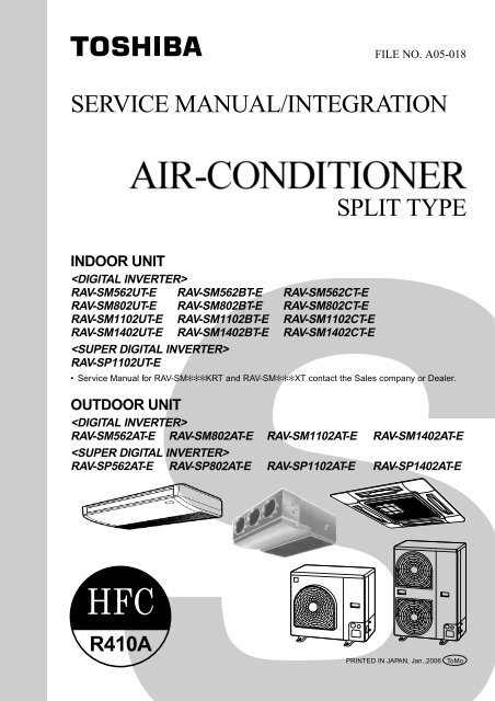
SERVICE MANUAL/INTEGRATION<br />
SPLIT TYPE<br />
INDOOR UNIT<br />
<br />
RAV-SM562UT-E RAV-SM562BT-E RAV-SM562CT-E<br />
RAV-SM802UT-E RAV-SM802BT-E RAV-SM802CT-E<br />
RAV-SM1102UT-E RAV-SM1102BT-E RAV-SM1102CT-E<br />
RAV-SM1402UT-E RAV-SM1402BT-E RAV-SM1402CT-E<br />
<br />
RAV-SP1102UT-E<br />
• Service Manual for RAV-SM✻✻✻KRT and RAV-SM✻✻✻XT contact the Sales company or Dealer.<br />
OUTDOOR UNIT<br />
<br />
RAV-SM562AT-E RAV-SM802AT-E RAV-SM1102AT-E RAV-SM1402AT-E<br />
<br />
RAV-SP562AT-E RAV-SP802AT-E RAV-SP1102AT-E RAV-SP1402AT-E<br />
R410A<br />
PRINTED IN JAPAN, Jan.,2006 ToMo
ADOPTION OF NEW REFRIGERANT<br />
This Air Conditioner is a new type which adopts a new refrigerant HFC (R410A) instead of the conventional<br />
refrigerant R22 in order to prevent destruction of the ozone layer.<br />
WARNING<br />
Cleaning of the air filter and other parts of the air filter involves dangerous work in high places, so be sure to have<br />
a service person do it. Do not attempt it yourself. The cleaning diagram for the air filter is there for the service<br />
person, and not for the customer.<br />
NOTE<br />
A direct current motor is adopted for <strong>indoor</strong> fan motor in the Concealed Duct Standard Type air conditioner.<br />
Caused from its characteristics, a current limit works on the direct current motor. When replacing the highperformance<br />
filter or when opening the service board, be sure to stop the fan. If an above action is executed<br />
during the fan operation, the protective control works to stop the <strong>unit</strong> operation, and the check code “P12”<br />
may be issued. However it is not a trouble. When the desired operation has finished, be sure to reset the<br />
system to clear “P12” error code using the leak breaker of the <strong>indoor</strong> <strong>unit</strong>. Then push the operation stop<br />
button of the remote controller to return to the usual operation.<br />
CONTENTS<br />
SAFETY CAUTION ............................................................................................ 4<br />
1. SPECIFICATIONS ...................................................................................... 9<br />
1-1. Indoor Unit........................................................................................................... 9<br />
1-2. Outdoor Unit...................................................................................................... 17<br />
1-3. Operation Characteristic Curve....................................................................... 19<br />
2. AIR DUCTING WORK .............................................................................. 22<br />
2-1. Static Pressure Characteristics of Each Model ............................................. 22<br />
3. CONSTRUCTION VIEWS (EXTERNAL VIEWS) ...................................... 24<br />
3-1. Indoor Unit......................................................................................................... 24<br />
3-2. Outdoor Unit...................................................................................................... 28<br />
4. SYSTEMATIC REFRIGERATING CYCLE DIAGRAM .............................. 31<br />
4-1. Indoor Unit/Outdoor Unit ................................................................................. 31<br />
5. WIRING DIAGRAM................................................................................... 39<br />
5-1. Indoor Unit......................................................................................................... 39<br />
5-2. Outdoor Unit (Wiring Diagram) ........................................................................ 42<br />
6. SPECIFICATIONS OF ELECTRICAL PARTS .......................................... 46<br />
6-1. Indoor Unit......................................................................................................... 46<br />
6-2. Outdoor Unit...................................................................................................... 48<br />
6-3. Accessory Separate Soldparts........................................................................ 50<br />
– 2 –
7. REFRIGERANT R410A ............................................................................ 51<br />
7-1. Safety During Installation/Servicing ............................................................... 51<br />
7-2. Refrigerant Piping Installation....................................................................... 51<br />
7-3. Tools .................................................................................................................. 55<br />
7-4. Recharging of Refrigerant ............................................................................... 55<br />
7-5. Brazing of Pipes................................................................................................ 56<br />
8. CONTROL BLOCK DIAGRAM................................................................. 58<br />
8-1. Indoor Control Circuit....................................................................................... 58<br />
8-2. Control Specifications ...................................................................................... 59<br />
8-3. Indoor Print Circuit Board ................................................................................ 68<br />
9. CIRCUIT CONFIGURATION AND CONTROL SPECIFICATIONS .......... 69<br />
9-1. Indoor Control Circuit....................................................................................... 69<br />
9-2. Outdoor Controls .............................................................................................. 70<br />
10. TROUBLESHOOTING .............................................................................. 79<br />
10-1. Summary of Troubleshooting........................................................................... 79<br />
10-2. Check Code List................................................................................................ 81<br />
10-3. Error Mode Detected by LED on Outdoor P.C. Board .................................... 84<br />
10-4. Troubleshooting Procedure for Each Check Code ........................................ 85<br />
11. REPLACEMENT OF SERVICE INDOOR P.C. BOARD.......................... 101<br />
12. SETUP AT LOCAL SITE AND OTHERS ................................................ 105<br />
12-1. Indoor Unit....................................................................................................... 105<br />
12-2. Setup at Local Site / Others ........................................................................... 112<br />
12-3. How to set up central control address Number ........................................... 114<br />
13. ADDRESS SETUP ................................................................................. 115<br />
13-1. Address Setup ................................................................................................ 115<br />
13-2. Address Setup & Group Control.................................................................... 116<br />
13-3. Address Setup ................................................................................................ 117<br />
14. DETACHMENTS ..................................................................................... 119<br />
14-1. Indoor Unit...................................................................................................... 119<br />
14-2. Outdoor Unit.................................................................................................... 135<br />
15. EXPLODED VIEWS AND PARTS LIST .................................................. 160<br />
15-1. Indoor Unit....................................................................................................... 160<br />
15-2. Outdoor Unit.................................................................................................... 174<br />
15-3. Replacement of Main Parts (Sold Separately).............................................. 182<br />
16. CORD HEATER INSTALLATION WORK ............................................... 184<br />
– 3 –
SAFETY CAUTION<br />
The important contents concerned to the safety are described on the product itself and on this Service Manual.<br />
Please read this Service Manual after understanding the described items thoroughly in the following contents<br />
(Indications/Illustrated marks), and keep them.<br />
[Explanation of indications]<br />
Indication<br />
DANGER<br />
WARNING<br />
CAUTION<br />
Explanation<br />
Indicates contents assumed that an imminent danger causing a death or serious injury of<br />
the repair engineers and the third parties when an incorrect work has been executed.<br />
Indicates possibilities assumed that a danger causing a death or serious injury of the<br />
repair engineers, the third parties, and the users due to troubles of the product after work<br />
when an incorrect work has been executed.<br />
Indicates contents assumed that an injury or property damage (∗) may be caused on the<br />
repair engineers, the third parties, and the users due to troubles of the product after work<br />
when an incorrect work has been executed.<br />
∗ Property damage : Enlarged damage concerned to property, furniture, and domestic animal/pet<br />
[Explanation of illustrated marks]<br />
Mark<br />
Explanation<br />
Indicates prohibited items (Forbidden items to do)<br />
The sentences near an illustrated mark describe the concrete prohibited contents.<br />
Indicates mandatory items (Compulsory items to do)<br />
The sentences near an illustrated mark describe the concrete mandatory contents.<br />
Indicates cautions (including danger/warning)<br />
The sentences or illustration near or in an illustrated mark describe the concrete cautious contents.<br />
[Confirmation of warning label on the main <strong>unit</strong>]<br />
Confirm that labels are indicated on the specified positions<br />
(Refer to the Parts disassembly diagram (Outdoor <strong>unit</strong>).)<br />
If removing the label during parts replace, stick it as the original.<br />
DANGER<br />
Turn off breaker.<br />
Execute discharge<br />
between terminals.<br />
Turn “OFF” the breaker before removing the front panel and cabinet, otherwise an electric<br />
shock is caused by high voltage resulted in a death or injury.<br />
During operation, a high voltage with 400V or higher of circuit (∗) at secondary circuit of the highvoltage<br />
transformer is applied.<br />
If touching a high voltage with the naked hands or body, an electric shock is caused even if using an<br />
electric insulator.<br />
∗ : For details, refer to the electric wiring diagram.<br />
When removing the front panel or cabinet, execute short-circuit and discharge between highvoltage<br />
capacitor terminals.<br />
If discharge is not executed, an electric shock is caused by high voltage resulted in a death or injury.<br />
After turning off the breaker, high voltage also keeps to apply to the high-voltage capacitor.<br />
Do not turn on the breaker under condition that the front panel and cabinet are removed.<br />
An electric shock is caused by high voltage resulted in a death or injury.<br />
Prohibition<br />
– 4 –
WARNING<br />
Check earth wires.<br />
Prohibition of modification.<br />
Use specified parts.<br />
Do not bring a child<br />
close to the equipment.<br />
Insulating measures<br />
No fire<br />
Refrigerant<br />
Assembly/Cabling<br />
Before troubleshooting or repair work, check the earth wire is connected to the earth<br />
terminals of the main <strong>unit</strong>, otherwise an electric shock is caused when a leak occurs.<br />
If the earth wire is not correctly connected, contact an electric engineer for rework.<br />
Do not modify the products.<br />
Do not also disassemble or modify the parts. It may cause a fire, electric shock or injury.<br />
For spare parts, use those specified (∗).<br />
If unspecified parts are used, a fire or electric shock may be caused.<br />
∗: For details, refer to the parts list.<br />
Before troubleshooting or repair work, do not bring a third party (a child, etc.) except<br />
the repair engineers close to the equipment.<br />
It causes an injury with tools or disassembled parts.<br />
Please inform the users so that the third party (a child, etc.) does not approach the equipment.<br />
Connect the cut-off lead cables with crimp contact, etc, put the closed end side<br />
upward and then apply a water-cut method, otherwise a leak or production of fire is<br />
caused at the users’ side.<br />
When repairing the refrigerating cycle, take the following measures.<br />
1) Be attentive to fire around the cycle. When using a gas stove, etc, be sure to put out fire<br />
before work; otherwise the oil mixed with refrigerant gas may catch fire.<br />
2) Do not use a welder in the closed room. When using it without ventilation, carbon<br />
monoxide poisoning may be caused.<br />
3) Do not bring inflammables close to the refrigerant cycle, otherwise fire of the welder may<br />
catch the inflammables.<br />
Check the used refrigerant name and use tools and materials of the parts which<br />
match with it.<br />
For the products which use R410A refrigerant, the refrigerant name is indicated at a<br />
position on the outdoor <strong>unit</strong> where is easy to see. To prevent miss-charging, the route of the<br />
service port is changed from one of the former R22.<br />
For an air conditioner which uses R410A, never use other refrigerant than R410A.<br />
For an air conditioner which uses other refrigerant (R22, etc.), never use R410A.<br />
If different types of refrigerant are mixed, abnormal high pressure generates in the refrigerating<br />
cycle and an injury due to breakage may be caused.<br />
Do not charge refrigerant additionally.<br />
If charging refrigerant additionally when refrigerant gas leaks, the refrigerant composition in<br />
the refrigerating cycle changes resulted in change of air conditioner characteristics or<br />
refrigerant over the specified standard amount is charged and an abnormal high pressure is<br />
applied to the inside of the refrigerating cycle resulted in cause of breakage or injury.<br />
Therefore if the refrigerant gas leaks, recover the refrigerant in the air conditioner, execute<br />
vacuuming, and then newly recharge the specified amount of liquid refrigerant. In this time,<br />
never charge the refrigerant over the specified amount.<br />
When recharging the refrigerant in the refrigerating cycle, do not mix the refrigerant<br />
or air other than R410A into the specified refrigerant.<br />
If air or others is mixed with the refrigerant, abnormal high pressure generates in the<br />
refrigerating cycle resulted in cause of injury due to breakage.<br />
After installation work, check the refrigerant gas does not leak.<br />
If the refrigerant gas leaks in the room, poisonous gas generates when gas touches to fire<br />
such as fan heater, stove or cocking stove though the refrigerant gas itself is innocuous.<br />
Never recover the refrigerant into the outdoor <strong>unit</strong>.<br />
When the equipment is moved or repaired, be sure to recover the refrigerant with recovering<br />
device. The refrigerant cannot be recovered in the outdoor <strong>unit</strong>; otherwise a serious<br />
accident such as breakage or injury is caused.<br />
After repair work, surely assemble the disassembled parts, and connect and lead the<br />
removed cables as before. Perform the work so that the cabinet or panel does not<br />
catch the inner cables.<br />
If incorrect assembly or incorrect cable connection was done, a disaster such as a leak or<br />
fire is caused at user’s side.<br />
– 5 –
WARNING<br />
Insulator check<br />
Ventilation<br />
Be attentive to<br />
electric shock<br />
Compulsion<br />
After the work has finished, be sure to use an insulation tester set (500V mugger) to<br />
check the resistance is 2MΩ or more between the charge section and the non-charge<br />
metal section (Earth position).<br />
If the resistance value is low, a disaster such as a leak or electric shock is caused at user’s<br />
side.<br />
When the refrigerant gas leaks during work, execute ventilation.<br />
If the refrigerant gas touches to a fire, poisonous gas generates. A case of leakage of the<br />
refrigerant and the closed room full with gas is dangerous because a shortage of oxygen<br />
occurs. Be sure to execute ventilation.<br />
When checking the circuit inevitably under condition of the power-ON, use rubber<br />
gloves and others not to touch to the charging section.<br />
If touching to the charging section, an electric shock may be caused.<br />
When the refrigerant gas leaks, find up the leaked position and repair it surely.<br />
If the leaked position cannot be found up and the repair work is interrupted, pump-down<br />
and tighten the service valve, otherwise the refrigerant gas may leak into the room.<br />
The poisonous gas generates when gas touches to fire such as fan heater, stove or cocking<br />
stove though the refrigerant gas itself is innocuous.<br />
When installing equipment which includes a large amount of charged refrigerant such<br />
as a multi air conditioner in a sub-room, it is necessary that the density does not the<br />
limit even if the refrigerant leaks.<br />
If the refrigerant leaks and exceeds the limit density, an accident of shortage of oxygen is<br />
caused.<br />
For the installation/moving/reinstallation work, follow to the Installation Manual.<br />
If an incorrect installation is done, a trouble of the refrigerating cycle, water leak, electric<br />
shock or fire is caused.<br />
After repair work has finished, check there is no trouble.<br />
If check is not executed, a fire, electric shock or injury may be caused. For a check, turn off<br />
the power breaker.<br />
Check after rerair<br />
Check after reinstallation<br />
After repair work (installation of front panel and cabinet) has finished, execute a test<br />
run to check there is no generation of smoke or abnormal sound.<br />
If check is not executed, a fire or an electric shock is caused. Before test run, install the<br />
front panel and cabinet.<br />
Check the following items after reinstallation.<br />
1) The earth wire is correctly connected.<br />
2) The power cord is not caught in the product.<br />
3) There is no inclination or unsteadiness and the installation is stable.<br />
If check is not executed, a fire, an electric shock or an injury is caused.<br />
CAUTION<br />
Put on gloves<br />
Cooling check<br />
Be sure to put on gloves (∗) during repair work.<br />
If not putting on gloves, an injury may be caused with the parts, etc.<br />
(∗) Heavy gloves such as work gloves<br />
When the power was turned on, start to work after the equipment has been<br />
sufficiently cooled.<br />
As temperature of the compressor pipes and others became high due to cooling/heating<br />
operation, a burn may be caused.<br />
– 6 –
• New Refrigerant (R410A)<br />
This air conditioner adopts a new HFC type refrigerant (R410A) which does not deplete the ozone layer.<br />
1. Safety Caution Concerned to New Refrigerant<br />
The pressure of R410A is high 1.6 times of that of the former refrigerant (R22). Accompanied with change of<br />
refrigerant, the refrigerating oil has been also changed. Therefore, be sure that water, dust, the former<br />
refrigerant or the former refrigerating oil is not mixed into the refrigerating cycle of the air conditioner with<br />
new refrigerant during installation work or service work. If an incorrect work or incorrect service is performed,<br />
there is a possibility to cause a serious accident. Use the tools and materials exclusive to R410A to<br />
purpose a safe work.<br />
2. Cautions on Installation/Service<br />
1) Do not mix the other refrigerant or refrigerating oil.<br />
For the tools exclusive to R410A, shapes of all the joints including the service port differ from those of the<br />
former refrigerant in order to prevent mixture of them.<br />
2) As the use pressure of the new refrigerant is high, use material thickness of the pipe and tools which are<br />
specified for R410A.<br />
3) In the installation time, use clean pipe materials and work with great attention so that water and others do<br />
not mix in because pipes are affected by impurities such as water, oxide scales, oil, etc. Use the clean<br />
pipes.<br />
Be sure to brazing with flowing nitrogen gas. (Never use gas other than nitrogen gas.)<br />
4) For the earth protection, use a vacuum pump for air purge.<br />
5) R410A refrigerant is azeotropic mixture type refrigerant. Therefore use liquid type to charge the refrigerant.<br />
(If using gas for charging, composition of the refrigerant changes and then characteristics of the air<br />
conditioner change.)<br />
3. Pipe Materials<br />
For the refrigerant pipes, copper pipe and joints are mainly used. It is necessary to select the most appropriate<br />
pipes to conform to the standard. Use clean material in which impurities adhere inside of pipe or joint to a<br />
minimum.<br />
1) Copper pipe<br />
<br />
The pipe thickness, flare finishing size, flare nut and others differ according to a refrigerant type.<br />
When using a long copper pipe for R410A, it is recommended to select “Copper or copper-base pipe without<br />
seam” and one with bonded oil amount 40mg/10m or less. Also do not use crushed, deformed, discolored<br />
(especially inside) pipes. (Impurities cause clogging of expansion valves and capillary tubes.)<br />
<br />
Use the flare nuts which are attached to the air conditioner <strong>unit</strong>.<br />
2) Joint<br />
The flare joint and socket joint are used for joints of the copper pipe. The joints are rarely used for installation<br />
of the air conditioner. However clear impurities when using them.<br />
– 7 –
4. Tools<br />
1. Required Tools for R410A<br />
Mixing of different types of oil may cause a trouble such as generation of sludge, clogging of capillary, etc.<br />
Accordingly, the tools to be used are classified into the following three types.<br />
1) Tools exclusive for R410A (Those which cannot be used for conventional refrigerant (R22))<br />
2) Tools exclusive for R410A, but can be also used for conventional refrigerant (R22)<br />
3) Tools commonly used for R410A and for conventional refrigerant (R22)<br />
The table below shows the tools exclusive for R410A and their interchangeability.<br />
Tools exclusive for R410A (The following tools for R410A are required.)<br />
Tools whose specifications are changed for R410A and their interchangeability<br />
No. Used tool Usage<br />
R410A<br />
air conditioner installation<br />
Existence of<br />
new equipment<br />
for R410A<br />
Whether<br />
conventional<br />
equipment can be<br />
used<br />
Conventional air<br />
conditioner installation<br />
Whether new equipment<br />
can be used with<br />
conventional refrigerant<br />
Flare tool Pipe flaring Yes *(Note 1) Yes<br />
‚<br />
Copper pipe gauge for<br />
adjusting projection<br />
margin<br />
Flaring by<br />
conventional flare tool<br />
Yes *(Note 1) *(Note 1)<br />
ƒ Torque wrench Connection of flare nut Yes No No<br />
„ Gauge manifold<br />
…<br />
Charge hose<br />
Evacuating, refrigerant<br />
charge, run check, etc.<br />
Yes No No<br />
† Vacuum pump adapter Vacuum evacuating Yes No Yes<br />
‡<br />
Electronic balance for<br />
refrigerant charging<br />
Refrigerant charge Yes Yes Yes<br />
ˆ Refrigerant cylinder Refrigerant charge Yes No No<br />
‰ Leakage detector Gas leakage check Yes No Yes<br />
Š Charging cylinder Refrigerant charge (Note 2) No No<br />
(Note 1) When flaring is carried out for R410A using the conventional flare tools, adjustment of projection<br />
margin is necessary. For this adjustment, a copper pipe gauge, etc. are necessary.<br />
(Note 2) Charging cylinder for R410A is being currently developed.<br />
1) Vacuum pump<br />
Use vacuum pump by<br />
attaching vacuum pump adapter.<br />
2) Torque wrench<br />
3) Pipe cutter<br />
4) Reamer<br />
5) Pipe bender<br />
6) Level vial<br />
General tools (Conventional tools can be used.)<br />
In addition to the above exclusive tools, the following equipments which serve also for R22 are necessary<br />
as the general tools.<br />
7) Screwdriver (+, –)<br />
8) Spanner or Monkey wrench<br />
9) Hole core drill<br />
10) Hexagon wrench (Opposite side 4mm)<br />
11) Tape measure<br />
12) Metal saw<br />
Also prepare the following equipments for other installation method and run check.<br />
1) Clamp meter<br />
3) IInsulation resistance tester<br />
2) Thermometer<br />
4) Electroscope<br />
– 8 –
1-1. Indoor Unit<br />
1-1-1. 4-Way Air Discharge Cassette Type<br />
<br />
Model<br />
1. SPECIFICATIONS<br />
Indoor <strong>unit</strong> RAV- SM562UT-E SM802UT-E SM1102UT-E SM1402UT-E<br />
Outdoor <strong>unit</strong> RAV- SM562AT-E SM802AT-E SM1102AT-E SM1402AT-E<br />
Cooling capacity (kW) 5.3 7.1 10.0 12.3<br />
Heating capacity (kW) 5.6 8.0 11.2 14.0<br />
Power supply<br />
Electrical<br />
characteristics<br />
Appearance<br />
Outer<br />
dimension<br />
Total weight<br />
Heat exchanger<br />
Cooling<br />
Heating<br />
Main <strong>unit</strong><br />
Ceiling panel<br />
(Sold separately)<br />
Main <strong>unit</strong><br />
Ceiling panel<br />
(Sold separately)<br />
1 phase 230V (220 – 240V) 50Hz<br />
Running current (A) 8.42 – 7.72 11.32 – 10.37 16.30 – 16.00 19.20 – 17.60<br />
Power consumption (kW) 1.76 2.34 3.52 4.09<br />
Power factor (%) 95 94 98 97<br />
EER (W/W) 3.01 3.03 2.84 3.01<br />
Energy efficiency class * B B C B<br />
Energy rating ** 3.5 3.5 3.0 3.5<br />
Running current (A) 6.89 – 6.32 11.22 – 10.28 16.10 – 14.80 18.70 – 17.20<br />
Power consumption (kW) 1.44 2.32 3.48 4.00<br />
Power factor (%) 95 94 98 97<br />
COP (W/W) 3.89 3.45 3.22 3.50<br />
Energy efficiency class * A B C B<br />
Energy rating ** 5.0 3.5 3.5 4.0<br />
Model<br />
Zinc hot dipping steel plate<br />
RBC-U21PG (W)-E2<br />
Panel color Moon-white (Muncel 2.5GY 9.0/0.5)<br />
Height (mm) 256 256 256 320<br />
Width (mm) 840 840 840 840<br />
Depth (mm) 840 840 840 840<br />
Height (mm) 35 35 35 35<br />
Width (mm) 950 950 950 950<br />
Depth (mm) 950 950 950 950<br />
Main <strong>unit</strong> (kg) 21 22 22 26<br />
Ceiling panel (Sold separately) (kg) 4.5 4.5 4.5 4.5<br />
Finned tube<br />
Fan Turbo fan Turbo fan Turbo fan Turbo fan<br />
Fan <strong>unit</strong> Standard air flow H/M/L (m³/min) 17.5/13.9/12.1 20.0/15.7/13.6 24.0/19.0/16.0 33.0/25.0/20.0<br />
Motor (W) 60 60 60 90<br />
Air filter<br />
TCB-LF1601UE, UFM1601UE, UFH1601UE<br />
Controller (Sold separately)<br />
RBC-AMT31E2, AS21E2, TCB-SC642TLE2, AX21U(W)-E2<br />
Gas side (mm) 12.7 15.9 15.9 15.9<br />
Connecting pipe<br />
Liquid side (mm) 6.4 9.5 9.5 9.5<br />
Drain port (mm) VP25<br />
Sound pressure level H/M/L (dB•A) 32/29/27 34/31/28 39/36/33 42/38/34<br />
Sound power level H/M/L (dB•A) 47/44/42 49/46/43 54/51/48 57/53/49<br />
* : IEC standard, ** : AS standard<br />
– 9 –
Model<br />
Indoor <strong>unit</strong> RAV- SM562UT-E SM802UT-E SM1102UT-E SM1402UT-E<br />
Outdoor <strong>unit</strong> RAV- SP562AT-E SP802AT-E SP1102AT-E SP1402AT-E<br />
Cooling capacity (kW) 5.3 7.1 10.0 12.5<br />
Heating capacity (kW) 5.6 8.0 11.2 14.0<br />
Power supply<br />
1 phase 230V (220 – 240V) 50Hz<br />
Running current (A) 7.17 – 6.57 8.95 – 8.21 11.24 – 10.31 16.51 – 15.14<br />
Power consumption (kW) 1.53 1.93 2.40 3.56<br />
Cooling<br />
Power factor (%) 97 98 97 98<br />
EER (W/W) 3.46 3.68 4.17 3.51<br />
Energy efficiency class * A A A A<br />
Electrical<br />
characteristics<br />
Energy rating ** — — — —<br />
Running current (A) 5.62 – 5.15 9.42 – 8.63 12.28 – 11.25 16.60 – 15.22<br />
Power consumption (kW) 1.20 2.03 2.62 3.58<br />
Heating<br />
Power factor (%) 97 98 97 98<br />
COP (W/W) 4.67 3.94 4.27 3.91<br />
Energy efficiency class * A A A A<br />
Energy rating ** — — — —<br />
Main <strong>unit</strong><br />
Zinc hot dipping steel plate<br />
Appearance<br />
Ceiling panel<br />
(Sold separately)<br />
Model<br />
RBC-U21PG (W)-E2<br />
Panel color Moon-white (Muncel 2.5GY 9.0/0.5)<br />
Height (mm) 256 256 320 320<br />
Main <strong>unit</strong><br />
Width (mm) 840 840 840 840<br />
Outer<br />
dimension<br />
Total weight<br />
Depth (mm) 840 840 840 840<br />
Height (mm) 35 35 35 35<br />
Ceiling panel<br />
(Sold separately)<br />
Width (mm) 950 950 950 950<br />
Depth (mm) 950 950 950 950<br />
Main <strong>unit</strong> (kg) 21 22 26 26<br />
Ceiling panel (Sold separately) (kg) 4.5 4.5 4.5 4.5<br />
Heat exchanger<br />
Finned tube<br />
Fan Turbo fan Turbo fan Turbo fan Turbo fan<br />
Fan <strong>unit</strong><br />
Standard air flow H/M/L (m³/min) 17.5/13.9/12.1 20.0/15.7/13.6 28.0/22.0/18.0 33.0/25.0/20.0<br />
Motor (W) 60 60 90 90<br />
Air filter<br />
Controller (Sold separately)<br />
TCB-LF1601UE, UFM1601UE, UFH1601UE<br />
RBC-AMT31E2, AS21E2, TCB-SC642TLE2, AX21U (W)-E2<br />
Gas side (mm) 12.7 15.9 15.9 15.9<br />
Connecting pipe<br />
Liquid side (mm) 6.4 9.5 9.5 9.5<br />
Drain port (mm) VP25<br />
Sound pressure level H/M/L (dB•A) 32/29/27 34/31/28 39/36/33 42/38/34<br />
Sound power level H/M/L (dB•A) 47/44/42 49/46/43 54/51/48 57/53/49<br />
* : IEC standard, ** : AS standard<br />
– 10 –
1-1-2. Concealed Duct Type<br />
<br />
Indoor <strong>unit</strong> RAV- SM562BT-E SM802BT-E SM1102BT-E SM1402BT-E<br />
Model<br />
Outdoor <strong>unit</strong> RAV- SM562AT-E SM802AT-E SM1102AT-E SM1402AT-E<br />
Cooling capacity (kW) 5.0 7.1 10.0 12.5<br />
Heating capacity (kW) 5.6 8.0 11.2 14.0<br />
Power supply<br />
1 phase 230V (220 – 240V) 50Hz<br />
Running current (A) 8.99 – 8.24 12.23 – 11.21 16.50 – 15.10 20.70 – 19.00<br />
Power consumption (kW) 1.78 2.53 3.56 4.42<br />
Electrical<br />
characteristics<br />
Cooling<br />
Power factor (%) 90 94 98 97<br />
EER (W/W) 2.81 2.81 2.81 2.83<br />
Energy efficiency class * C C C C<br />
Energy rating ** 3.0 3.0 3.5 3.0<br />
Running current (A) 8.18 – 7.50 11.65 – 10.68 14.56 – 13.35 18.88 – 17.31<br />
Appearance<br />
Outer<br />
dimension<br />
Total weight<br />
Heat exchanger<br />
Fan <strong>unit</strong><br />
Air filter<br />
Heating<br />
Main <strong>unit</strong><br />
Ceiling panel<br />
(Sold separately)<br />
Main <strong>unit</strong><br />
Controller (Sold separately)<br />
Connecting pipe<br />
Power consumption (kW) 1.71 2.41 3.14 4.03<br />
Power factor (%) 95 94 98 97<br />
COP (W/W) 3.27 3.32 3.57 3.47<br />
Energy efficiency class * C C B B<br />
Energy rating ** 3.0 3.5 5.0 4.0<br />
Zinc hot dipping steel plate<br />
Model —<br />
Panel color —<br />
Height (mm) 320 320 320 320<br />
Width (mm) 700 1000 1350 1350<br />
Depth (mm) 800 800 800 800<br />
Height (mm) — — — —<br />
Ceiling panel<br />
(Sold separately)<br />
Width (mm) — — — —<br />
Depth (mm) — — — —<br />
Main <strong>unit</strong> (kg) 30 39 54 54<br />
Ceiling panel (Sold separately) (kg) — — — —<br />
Finned tube<br />
Fan Centrifugal Centrifugal Centrifugal Centrifugal<br />
Standard air flow H/M/L (m³/min) 13.0/11.9/9.8 19.0/16.2/13.3 27.0/23.0/18.9 33.0/28.0/23.1<br />
Motor (W) 120 120 120 120<br />
TCB-<br />
UFM21BE<br />
UFM61BE<br />
UFM11BFCE<br />
UFM31BE<br />
UFH51BFCE<br />
UFM71BE<br />
UFM21BFCE<br />
UFM 41BE<br />
UFH61BFCE<br />
UFH 81BE<br />
RBC-AMT31E2, AS21E2, TCB-SC642TLE2, AX21E2<br />
Gas side (mm) 12.7 15.9 15.9 15.9<br />
Liquid side (mm) 6.4 9.5 9.5 9.5<br />
Drain port (mm) VP25<br />
Sound pressure level H/M/L (dB•A) 40/37/33 40/37/34 42/39/36 44/41/38<br />
Sound power level H/M/L (dB•A) 55/52/48 55/52/49 57/54/51 59/56/53<br />
* : IEC standard, ** : AS standard<br />
– 11 –
Indoor <strong>unit</strong> RAV- SM562BT-E SM802BT-E SM1102BT-E SM1402BT-E<br />
Model<br />
Outdoor <strong>unit</strong> RAV- SP562AT-E SP802AT-E SP1102AT-E SP1402AT-E<br />
Cooling capacity (kW) 5.0 7.1 10.0 12.5<br />
Heating capacity (kW) 5.6 8.0 11.2 14.0<br />
Power supply<br />
1 phase 230V (220 – 240V) 50Hz<br />
Running current (A) 6.51 – 5.97 9.74 – 8.93 11.72 – 10.74 18.09 – 16.58<br />
Power consumption (kW) 1.39 2.10 2.50 3.90<br />
Electrical<br />
characteristics<br />
Cooling<br />
Power factor (%) 97 98 97 98<br />
EER (W/W) 3.60 3.38 4.00 3.21<br />
Energy efficiency class * A A A A<br />
Energy rating ** — — — —<br />
Running current (A) 7.26 – 6.66 9.74 – 8.93 11.72 – 10.74 16.70 – 15.31<br />
Appearance<br />
Outer<br />
dimension<br />
Total weight<br />
Heat exchanger<br />
Fan <strong>unit</strong><br />
Air filter<br />
Heating<br />
Main <strong>unit</strong><br />
Ceiling panel<br />
(Sold separately)<br />
Main <strong>unit</strong><br />
Controller (Sold separately)<br />
Connecting pipe<br />
Power consumption (kW) 1.55 2.10 2.50 3.60<br />
Power factor (%) 97 98 97 98<br />
COP (W/W) 3.61 3.81 4.48 3.89<br />
Energy efficiency class * A A A A<br />
Energy rating ** — — — —<br />
Zinc hot dipping steel plate<br />
Model —<br />
Panel color —<br />
Height (mm) 320 320 320 320<br />
Width (mm) 700 1000 1350 1350<br />
Depth (mm) 800 800 800 800<br />
Height (mm) — — — —<br />
Ceiling panel<br />
(Sold separately)<br />
Width (mm) — — — —<br />
Depth (mm) — — — —<br />
Main <strong>unit</strong> (kg) 30 39 54 54<br />
Ceiling panel (Sold separately) (kg) — — — —<br />
Finned tube<br />
Fan Centrifugal Centrifugal Centrifugal Centrifugal<br />
Standard air flow H/M/L (m³/min) 13.0/11.9/9.8 19.0/16.2/13.3 27.0/23.0/18.9 33.0/28.0/23.1<br />
Motor (W) 120 120 120 120<br />
TCB-<br />
UFM21BE<br />
UFM61BE<br />
UFM11BFCE<br />
UFM31BE<br />
UFH51BFCE<br />
UFM71BE<br />
UFM21BFCE<br />
UFM 41BE<br />
UFH61BFCE<br />
UFH 81BE<br />
RBC-AMT31E2, AS21E2, TCB-SC642TLE2, AX21E2<br />
Gas side (mm) 12.7 15.9 15.9 15.9<br />
Liquid side (mm) 6.4 9.5 9.5 9.5<br />
Drain port (mm) VP25<br />
Sound pressure level H/M/L (dB•A) 40/37/33 40/37/34 42/39/36 44/41/38<br />
Sound power level H/M/L (dB•A) 55/52/48 55/52/49 57/54/51 59/56/53<br />
* : IEC standard, ** : AS standard<br />
– 12 –
1-1-3. Under Ceiling Type<br />
<br />
Model<br />
Indoor <strong>unit</strong> RAV- SM562CT-E SM802CT-E SM1102CT-E SM1402CT-E<br />
Outdoor <strong>unit</strong> RAV- SM562AT-E SM802AT-E SM1102AT-E SM1402AT-E<br />
Cooling capacity (kW) 5.0 7.0 10.0 12.3<br />
Heating capacity (kW) 5.6 8.0 11.2 14.0<br />
Power supply<br />
1 phase 230V (220 – 240V) 50Hz<br />
Running current (A) 8.71 – 7.98 12.23 – 11.21 16.20 – 14.90 21.18 – 19.40<br />
Power consumption (kW) 1.82 2.53 3.51 4.52<br />
Cooling<br />
Power factor (%) 95 94 98 97<br />
EER (W/W) 2.75 2.77 2.85 2.72<br />
Energy efficiency class * D D C D<br />
Electrical<br />
characteristics<br />
Energy rating ** 2.5 2.5 3.0 2.5<br />
Running current (A) 7.85 – 7.19 11.94 – 10.95 14.84 – 13.61 19.40 – 17.78<br />
Power consumption (kW) 1.64 2.47 3.20 4.14<br />
Heating<br />
Power factor (%) 95 94 98 97<br />
COP (W/W) 3.41 3.24 3.50 3.38<br />
Energy efficiency class * B C B C<br />
Energy rating ** 4.0 4.0 5.0 3.5<br />
Main <strong>unit</strong><br />
Shine white<br />
Appearance<br />
Ceiling panel<br />
(Sold separately)<br />
Model —<br />
Panel color —<br />
Height (mm) 210 210 210 210<br />
Main <strong>unit</strong><br />
Width (mm) 910 1180 1595 1595<br />
Outer<br />
dimension<br />
Total weight<br />
Depth (mm) 680 680 680 680<br />
Height (mm) — — — —<br />
Ceiling panel<br />
(Sold separately)<br />
Width (mm) — — — —<br />
Depth (mm) — — — —<br />
Main <strong>unit</strong> (kg) 21 25 33 33<br />
Ceiling panel (Sold separately) (kg) — — — —<br />
Heat exchanger<br />
Finned tube<br />
Fan Centrifugal Centrifugal Centrifugal Centrifugal<br />
Fan <strong>unit</strong><br />
Standard air flow H/M/L (m³/min) 13.0/11.2/10.0 18.5/16.7/14.6 27.5/24.0/21.2 30.0/26.0/23.1<br />
Motor (W) 30 40 80 80<br />
Air filter<br />
Controller (Sold separately)<br />
Attached main <strong>unit</strong><br />
RBC-AMT31E2, AS21E2, TCB-SC642TLE2, AX21E2<br />
Gas side (mm) 12.7 15.9 15.9 15.9<br />
Connecting pipe<br />
Liquid side (mm) 6.4 9.5 9.5 9.5<br />
Drain port (mm) VP25<br />
Sound pressure level H/M/L (dB•A) 36/33/30 38/36/33 41/38/35 43/40/37<br />
Sound power level H/M/L (dB•A) 51/48/45 53/51/48 56/53/50 58/55/52<br />
* : IEC standard, ** : AS standard<br />
– 13 –
Model<br />
Indoor <strong>unit</strong> RAV- SM562CT-E SM802CT-E SM1102CT-E SM1402CT-E<br />
Outdoor <strong>unit</strong> RAV- SP562AT-E SP802AT-E SP1102AT-E SP1402AT-E<br />
Cooling capacity (kW) 5.0 7.1 10.0 12.5<br />
Heating capacity (kW) 5.6 8.0 11.2 14.0<br />
Power supply<br />
1 phase 230V (220 – 240V) 50Hz<br />
Running current (A) 6.61 – 6.06 9.47 – 8.93 11.24 – 10.31 18.09 – 16.58<br />
Power consumption (kW) 1.41 2.10 2.40 3.90<br />
Cooling<br />
Power factor (%) 97 98 97 98<br />
EER (W/W) 3.55 3.38 4.17 3.21<br />
Energy efficiency class * A A A A<br />
Electrical<br />
characteristics<br />
Energy rating ** — — — —<br />
Running current (A) 7.03 – 6.44 10.20 – 9.35 11.72 – 10.74 17.39 – 15.94<br />
Power consumption (kW) 1.50 2.20 2.50 3.75<br />
Heating<br />
Power factor (%) 97 98 97 98<br />
COP (W/W) 3.73 3.64 4.48 3.73<br />
Energy efficiency class * A A A A<br />
Energy rating ** — — — —<br />
Main <strong>unit</strong><br />
Shine white<br />
Appearance<br />
Ceiling panel<br />
(Sold separately)<br />
Model —<br />
Panel color —<br />
Height (mm) 210 210 210 210<br />
Main <strong>unit</strong><br />
Width (mm) 910 1180 1595 1595<br />
Outer<br />
dimension<br />
Total weight<br />
Depth (mm) 680 680 680 680<br />
Height (mm) — — — —<br />
Ceiling panel<br />
(Sold separately)<br />
Width (mm) — — — —<br />
Depth (mm) — — — —<br />
Main <strong>unit</strong> (kg) 21 25 33 33<br />
Ceiling panel (Sold separately) (kg) — — — —<br />
Heat exchanger<br />
Finned tube<br />
Fan Centrifugal Centrifugal Centrifugal Centrifugal<br />
Fan <strong>unit</strong><br />
Standard air flow H/M/L (m³/min) 13.0/11.2/10.0 18.5/16.7/14.6 27.5/24.0/21.2 30.0/26.0/23.1<br />
Motor (W) 30 40 80 80<br />
Air filter<br />
Controller (Sold separately)<br />
Attached main <strong>unit</strong><br />
RBC-AMT31E2, AS21E2, TCB-SC642TLE2, AX21E2<br />
Gas side (mm) 12.7 15.9 15.9 15.9<br />
Connecting pipe<br />
Liquid side (mm) 6.4 9.5 9.5 9.5<br />
Drain port (mm) VP25<br />
Sound pressure level H/M/L (dB•A) 36/33/30 38/36/33 41/38/35 43/40/37<br />
Sound power level H/M/L (dB•A) 51/48/45 53/51/48 56/53/50 58/55/52<br />
* : IEC standard, ** : AS standard<br />
– 14 –
1-1-4. Twin Type<br />
<br />
Type 4-Way Air Cassette Concealed Duct Under Ceiling<br />
Model<br />
Indoor <strong>unit</strong> 1 RAV- SM562UT-E SM802UT-E SM562BT-E SM802BT-E SM562CT-E SM802CT-E<br />
Indoor <strong>unit</strong> 2 RAV- SM562UT-E SM802UT-E SM562BT-E SM802BT-E SM562CT-E SM802CT-E<br />
Outdoor <strong>unit</strong> RAV- SM1102AT-E SM1402AT-E SM1102AT-E SM1402AT-E SM1102AT-E SM1402AT-E<br />
Cooling capacity (kW) 10.0 12.5 10.0 12.5 10.0 12.3<br />
Heating capacity (kW) 11.2 14.0 11.2 14.0 11.2 14.0<br />
Indoor <strong>unit</strong><br />
Power supply<br />
1 phase 230V (220 – 240V) 50Hz<br />
Running current (A) 16.33–14.97 19.17–17.57 16.51–15.14 20.71–18.99 16.28–14.92 21.18–19.42<br />
Power consumption (kW) 3.52 4.09 3.56 4.42 3.51 4.52<br />
Cooling<br />
Power factor (%) 98 97 98 97 98 97<br />
EER (W/W) 2.84 3.06 2.81 2.83 2.85 2.72<br />
Electrical<br />
characteristics<br />
Energy efficiency class * C B C C C D<br />
Running current (A) 14.56–13.35 18.74–17.18 14.56–13.35 18.88–17.31 14.84–13.61 19.40–17.78<br />
Power consumption (kW) 3.14 4.00 3.14 4.03 3.20 4.14<br />
Heating<br />
Power factor (%) 98 97 98 97 98 97<br />
COP (W/W) 3.57 3.50 3.57 3.47 3.50 3.38<br />
Energy efficiency class * B B B B B C<br />
Fan Turbo fan Turbo fan Centrifugal Centrifugal Centrifugal Centrifugal<br />
Fan <strong>unit</strong><br />
Standard air flow H/M/L (m³/min) 17.5/13.9/12.1 20.0/15.7/13.6 13.0/11.9/9.8 19.0/16.2/13.3 13.0/11.2/10.0 18.5/16.7/14.6<br />
Motor (W) 60 60 120 120 30 40<br />
Sound pressure level H/M/L (dB•A) 32/29/27 34/31/28 40/37/33 40/37/34 36/33/30 38/36/33<br />
Sound power level H/M/L (dB•A) 47/44/42 49/46/43 55/52/48 55/52/49 51/48/45 53/51/48<br />
Outdoor <strong>unit</strong><br />
Power supply<br />
1 phase 230V (220 – 240V) 50Hz (Power exclusive to outdoor is required.)<br />
Standard length (m) 7.5 7.5 7.5 7.5 7.5 7.5<br />
Min. length (m) 5.0 5.0 5.0 5.0 5.0 5.0<br />
Inter<br />
connecting<br />
pipes<br />
Max. total length (m) 50 50 50 50 50 50<br />
Over 30m 40g/m (31m to 50m)<br />
Height<br />
difference<br />
Fan<br />
Outdoor lower (m) 30 30 30 30 30 30<br />
Outdoor high (m) 30 30 30 30 30 30<br />
Propeller fan<br />
Fan <strong>unit</strong><br />
Standard air flow high (m³/min) 75 75 75 75 75 75<br />
Motor (W) 100 100 100 100 100 100<br />
Connecting<br />
pipe<br />
Gas side<br />
Liquid side<br />
Main (mm) 15.9 15.9 15.9 15.9 15.9 15.9<br />
Sub (mm) 12.7 15.9 12.7 15.9 12.7 15.9<br />
Main (mm) 9.5 9.5 9.5 9.5 9.5 9.5<br />
Sub (mm) 6.4 9.5 6.4 9.5 6.4 9.5<br />
Sound pressure level Cooling/Heating (dB•A) 53/54 53/54 53/54 53/54 53/54 53/54<br />
Sound power level Cooling/Heating (dB•A) 70/71 70/71 70/71 70/71 70/71 70/71<br />
* : IEC standard<br />
– 15 –
Type 4-Way Air Cassette Concealed Duct Under Ceiling<br />
Model<br />
Indoor <strong>unit</strong> 1 RAV- SM562UT-E SM802UT-E SM562BT-E SM802BT-E SM562CT-E SM802CT-E<br />
Indoor <strong>unit</strong> 2 RAV- SM562UT-E SM802UT-E SM562BT-E SM802BT-E SM562CT-E SM802CT-E<br />
Outdoor <strong>unit</strong> RAV- SP1102AT-E SP1402AT-E SP1102AT-E SP1402AT-E SP1102AT-E SP1402AT-E<br />
Cooling capacity (kW) 10.0 12.5 10.0 12.5 10.0 12.3<br />
Heating capacity (kW) 11.2 14.0 11.2 14.0 11.2 14.0<br />
Indoor <strong>unit</strong><br />
Power supply<br />
1 phase 230V (220 – 240V) 50Hz<br />
Running current (A) 11.24–10.31 16.51–15.14 11.72–10.74 18.09–16.58 11.24–10.31 18.09–16.58<br />
Power consumption (kW) 2.40 3.56 2.50 3.90 2.40 3.90<br />
Cooling<br />
Power factor (%) 97 98 97 98 97 98<br />
EER (W/W) 4.17 3.51 4.00 3.21 4.17 3.21<br />
Electrical<br />
characteristics<br />
Energy efficiency class * A A A A A A<br />
Running current (A) 11.95–10.95 16.60–15.22 11.95–10.95 16.70–15.31 11.95–10.95 17.39–15.94<br />
Power consumption (kW) 2.55 3.58 2.55 3.60 2.55 3.75<br />
Heating<br />
Power factor (%) 97 98 97 98 97 98<br />
COP (W/W) 4.39 3.91 4.39 3.89 4.39 3.79<br />
Energy efficiency class * A A A A A A<br />
Fan Turbo fan Turbo fan Centrifugal Centrifugal Centrifugal Centrifugal<br />
Fan <strong>unit</strong><br />
Standard air flow H/M/L (m³/min) 17.5/13.9/12.1 20.0/15.7/13.6 13.0/11.9/9.8 19.0/16.2/13.3 13.0/11.2/10.0 18.5/16.7/14.6<br />
Motor (W) 60 60 120 120 30 40<br />
Sound pressure level H/M/L (dB•A) 32/29/27 34/31/28 40/37/33 40/37/34 36/33/30 38/36/33<br />
Sound power level H/M/L (dB•A) 47/44/42 49/46/43 55/52/48 55/52/49 51/48/45 53/51/48<br />
Outdoor <strong>unit</strong><br />
Power supply<br />
1 phase 230V (220 – 240V) 50Hz (Power exclusive to outdoor is required.)<br />
Standard length (m) 7.5 7.5 7.5 7.5 7.5 7.5<br />
Min. length (m) 5.0 5.0 5.0 5.0 5.0 5.0<br />
Inter<br />
connecting<br />
pipes<br />
Max. total length (m) 50 50 50 50 50 50<br />
Over 30m 40g/m (31m to 50m)<br />
Height<br />
difference<br />
Fan<br />
Outdoor lower (m) 30 30 30 30 30 30<br />
Outdoor high (m) 30 30 30 30 30 30<br />
Propeller fan<br />
Fan <strong>unit</strong><br />
Standard air flow high (m³/min) 125 125 125 125 125 125<br />
Motor (W) 63 + 63 63 + 63 63 + 63 63 + 63 63 + 63 63 + 63<br />
Connecting<br />
pipe<br />
Gas side<br />
Liquid side<br />
Main (mm) 15.9 15.9 15.9 15.9 15.9 15.9<br />
Sub (mm) 12.7 15.9 12.7 15.9 12.7 15.9<br />
Main (mm) 9.5 9.5 9.5 9.5 9.5 9.5<br />
Sub (mm) 6.4 9.5 6.4 9.5 6.4 9.5<br />
Sound pressure level Cooling/Heating (dB•A) 49/51 53/54 49/51 53/54 49/51 53/54<br />
Sound power level Cooling/Heating (dB•A) 66/68 70/71 66/68 70/71 66/68 70/71<br />
* : IEC standard<br />
– 16 –
1-2. Outdoor Unit<br />
<br />
Model name RAV- SM562AT-E SM802AT-E SM1102AT-E SM1402AT-E<br />
Power supply<br />
1 phase 230V (220 – 240V) 50Hz (Power exclusive to outdoor is required.)<br />
Type<br />
Hermetic compressor<br />
Compressor<br />
Motor (kW) 1.1 1.6 2.5 3.0<br />
Pole 4 4 4 4<br />
Refrigerant charged (kg) 1.0 1.7 2.8 2.8<br />
Refrigerant control<br />
Pulse motor valve<br />
Inter connecting<br />
pipe<br />
Standard length (m) 7.5 7.5 7.5 7.5<br />
Min. length (m) 5.0 5.0 5.0 5.0<br />
Max. total length (m) 30 30 50 50<br />
Additional refrigerant charge under<br />
long piping connector<br />
20g/m<br />
(21m to 30m)<br />
40g/m<br />
(21m to 30m)<br />
40g/m<br />
(31m to 50m)<br />
40g/m<br />
(31m to 50m)<br />
Outdoor lower (m) 30 30 30 30<br />
Height<br />
difference Outdoor higher (m) 30 30 30 30<br />
Outer<br />
dimension<br />
Appearance<br />
Height (mm) 550 550 795 795<br />
Width (mm) 780 780 900 900<br />
Depth (mm) 290 290 320 320<br />
Silky shade (Muncel 1Y8.5/0.5)<br />
Total weight (kg) 38 42 77 77<br />
Heat exchanger<br />
Finned tube<br />
Fan<br />
Propeller fan<br />
Fan <strong>unit</strong><br />
Standard air flow (m³/h) 40 45 75 75<br />
Motor (W) 43 43 100 100<br />
Connecting pipe<br />
Gas side (mm) 12.7 15.9 15.9 15.9<br />
Liquid side (mm) 6.4 9.5 9.5 9.5<br />
Sound pressure level Cooling/Heating (dB•A) 46/48 48/50 53/54 53/54<br />
Sound power level Cooling/Heating (dB•A) 63/65 65/67 70/71 70/71<br />
Outside air temperature, Cooling (°C) 43 to –15<br />
Outside air temperature, Heating (°C) 15 to –15<br />
– 17 –
Model name RAV- SP562AT-E SP802AT-E SP1102AT-E SP1402AT-E<br />
Power supply<br />
1 phase 230V (220 – 240V) 50Hz (Power exclusive to outdoor is required.)<br />
Type<br />
Hermetic compressor<br />
Compressor<br />
Motor (kW) 2.0 2.0 3.75 3.75<br />
Pole 4 4 4 4<br />
Refrigerant charged (kg) 1.5 2.1 2.95 2.95<br />
Refrigerant control<br />
Pulse motor valve<br />
Inter connecting<br />
pipe<br />
Standard length (m) 7.5 7.5 7.5 7.5<br />
Min. length (m) 5.0 5.0 5.0 5.0<br />
Max. total length (m) 50 50 70 70<br />
Additional refrigerant charge under<br />
long piping connector<br />
20g/m<br />
(21m to 50m)<br />
40g/m<br />
(31m to 50m)<br />
40g/m<br />
(31m to 70m)<br />
40g/m<br />
(31m to 70m)<br />
Outdoor lower (m) 30 30 30 30<br />
Height<br />
difference Outdoor higher (m) 30 30 30 30<br />
Outer<br />
dimension<br />
Appearance<br />
Height (mm) 795 795 1340 1340<br />
Width (mm) 900 900 900 900<br />
Depth (mm) 320 320 320 320<br />
Silky shade (Muncel 1Y8.5/0.5)<br />
Total weight (kg) 55 62 95 95<br />
Heat exchanger<br />
Finned tube<br />
Fan<br />
Propeller fan<br />
Fan <strong>unit</strong><br />
Standard air flow (m³/h) 57 57 125 125<br />
Motor (W) 63 63 63 + 63 63 + 63<br />
Connecting pipe<br />
Gas side (mm) 12.7 15.9 15.9 15.9<br />
Liquid side (mm) 6.4 9.5 9.5 9.5<br />
Sound pressure level Cooling/Heating (dB•A) 46/47 47/49 49/51 53/54<br />
Sound power level Cooling/Heating (dB•A) 63/64 64/66 66/68 70/71<br />
Outside air temperature, Cooling (°C) 43 to –15<br />
Outside air temperature, Heating (°C) 15 to –15<br />
– 18 –
1-3. Operation Characteristic Curve<br />
• Operation characteristic curve <br />
RAV-SM562AT-E, RAV-SM802AT-E<br />
<br />
<br />
14<br />
16<br />
12<br />
10<br />
RAV-SM802AT-E<br />
14<br />
12<br />
RAV-SM802AT-E<br />
Current (A)<br />
8<br />
6<br />
4<br />
2<br />
RAV-SM562AT-E<br />
• Conditions<br />
Indoor : DB27˚C/WB19˚C<br />
Outdoor : DB35˚C<br />
Air flow : High<br />
Pipe length : 7.5m<br />
230V<br />
Current (A)<br />
10<br />
8<br />
6<br />
4<br />
2<br />
RAV-SM562AT-E<br />
• Conditions<br />
Indoor : DB20˚C<br />
Outdoor : DB7˚C/WB6˚C<br />
Air flow : High<br />
Pipe length : 7.5m<br />
230V<br />
0<br />
0 20 40 60 70 80 90 100<br />
Compressor speed (rps)<br />
0 0 20 40 60 80 100 120<br />
Compressor speed (rps)<br />
RAV-SM1102AT-E, RAV-SM1402AT-E<br />
<br />
<br />
22 22<br />
20<br />
20<br />
18<br />
RAV-SM1102AT-E<br />
18<br />
16<br />
RAV-SM1402AT-E<br />
16<br />
RAV-SM1402AT-E<br />
14<br />
14<br />
Current (A)<br />
12<br />
10<br />
8<br />
Current (A)<br />
12<br />
10<br />
8<br />
RAV-SM1102AT-E<br />
6<br />
4<br />
2<br />
0<br />
0 20 40 60<br />
• Conditions<br />
Indoor : DB27˚C/WB19˚C<br />
Outdoor : DB35˚C<br />
Air flow : High<br />
Pipe length : 7.5m<br />
230V<br />
Compressor speed (rps)<br />
80 100 120<br />
6<br />
4<br />
2<br />
0<br />
0 20 40 60<br />
• Conditions<br />
Indoor : DB20˚C<br />
Outdoor : DB7˚C/WB6˚C<br />
Air flow : High<br />
Pipe length : 7.5m<br />
230V<br />
Compressor speed (rps)<br />
80 100 120<br />
– 19 –
• Operation characteristic curve <br />
RAV-SP562AT-E, RAV-SP802AT-E<br />
<br />
<br />
14<br />
16<br />
12<br />
14<br />
10<br />
RAV-SP802AT-E<br />
12<br />
RAV-SP802AT-E<br />
Current (A)<br />
8<br />
6<br />
4<br />
2<br />
RAV-SP562AT-E<br />
• Conditions<br />
Indoor : DB27˚C/WB19˚C<br />
Outdoor : DB35˚C<br />
Air flow : High<br />
Pipe length : 7.5m<br />
230V<br />
Current (A)<br />
10<br />
8<br />
6<br />
4<br />
2<br />
RAV-SP562AT-E<br />
• Conditions<br />
Indoor : DB20˚C<br />
Outdoor : DB7˚C/WB6˚C<br />
Air flow : High<br />
Pipe length : 7.5m<br />
230V<br />
0 0 20 40 50 60 70 80 100<br />
Compressor speed (rps)<br />
0 0 20 40 60 70 80 90 100<br />
Compressor speed (rps)<br />
RAV-SP1102AT-E, RAV-SP1402AT-E<br />
<br />
22<br />
<br />
22<br />
20<br />
20<br />
18<br />
RAV-SP1402AT-E<br />
18<br />
RAV-SP1402AT-E<br />
16<br />
16<br />
14<br />
14<br />
Current (A)<br />
12<br />
10<br />
Current (A)<br />
12<br />
10<br />
8<br />
6<br />
RAV-SP1102AT-E<br />
8<br />
6<br />
RAV-SP1102AT-E<br />
4<br />
2<br />
• Conditions<br />
Indoor : DB27˚C/WB19˚C<br />
Outdoor : DB35˚C<br />
Air flow : High<br />
Pipe length : 7.5m<br />
230V<br />
4<br />
2<br />
• Conditions<br />
Indoor : DB20˚C<br />
Outdoor : DB7˚C/WB6˚C<br />
Air flow : High<br />
Pipe length : 7.5m<br />
230V<br />
0<br />
0 20 40 60 80<br />
0<br />
0 20 40 60 80<br />
Compressor speed (rps)<br />
Compressor speed (rps)<br />
– 20 –
• Capacity variation ratio according to temperature<br />
RAV-SM562AT-E, RAV-SM802AT-E, RAV-SM1102AT-E, RAV-SM1402AT-E<br />
RAV-SP562AT-E, RAV-SP802AT-E, RAV-SP1102AT-E, RAV-SP1402AT-E<br />
<br />
<br />
105<br />
120<br />
100<br />
110<br />
95<br />
100<br />
90<br />
90<br />
Capacity ratio (%)<br />
85<br />
80<br />
75<br />
70<br />
Capacity ratio (%)<br />
80<br />
70<br />
60<br />
50<br />
40<br />
65<br />
30<br />
60<br />
• Conditions<br />
55<br />
Indoor : DB27˚C/WB19˚C<br />
Indoor air flow : High<br />
Pipe length : 7.5m<br />
50<br />
32 33 34 35 36 37 38 39 40 41 42 43<br />
20<br />
10<br />
0<br />
• Conditions<br />
Indoor : DB20˚C<br />
Indoor air flow : High<br />
Pipe length : 7.5m<br />
-14 -12 -10 -8 -6 -4 -2 0 2 4 6 8 10<br />
Outsoor temp. (˚C)<br />
Outsoor temp. (˚C)<br />
– 21 –
2. AIR DUCTING WORK<br />
2-1. Static Pressure Characteristics of Each Model<br />
RAV-SM562BT-E, RAV-SM802BT-E, RAV-SM1102BT-E, RAV-SM1402BT-E<br />
Fig. 1 RAV-SM562BT-E (Round duct)<br />
Fig. 3 RAV-SM802BT-E (Round duct)<br />
140<br />
Standard air volume 780m³/h<br />
140<br />
Standard air volume 1140m³/h<br />
120<br />
120<br />
100<br />
Usable limit<br />
High static pressure 2H tap<br />
100<br />
Usable limit<br />
High static pressure 2H tap<br />
Static pressure (Pa)<br />
80<br />
60<br />
40<br />
20<br />
Air volume limit (Min.)<br />
High static pressure 1H tap<br />
Standard H tap<br />
Low static pressure H tap<br />
Standard L tap<br />
Air volume limit (Max.)<br />
Static pressure (Pa)<br />
80<br />
60<br />
40<br />
20<br />
Air volume limit (Min.)<br />
High static pressure 1H tap<br />
Standard H tap<br />
Low static pressure H tap<br />
Standard L tap<br />
Air volume limit (Max.)<br />
0<br />
500 700 780 900<br />
Air volume m³/h<br />
0<br />
800 1000 1140 1200 1300<br />
Air volume m³/h<br />
Fig. 2 RAV-SM562BT-E (Square duct)<br />
Fig. 4 RAV-SM802BT-E (Square duct)<br />
140<br />
Standard air volume 780m³/h<br />
140<br />
Standard air volume 1140m³/h<br />
High static pressure 2H tap<br />
120<br />
108<br />
100<br />
Usable limit<br />
120<br />
100<br />
Usable limit<br />
High static pressure 2H tap<br />
High static pressure 1H tap<br />
Static pressure (Pa)<br />
80<br />
60<br />
40<br />
Air volume limit (Min.)<br />
High static pressure 1H tap<br />
Standard H tap<br />
Low static pressure H tap<br />
Air volume limit (Max.)<br />
Static pressure (Pa)<br />
80<br />
60<br />
40<br />
Air volume limit (Min.)<br />
Standard H tap<br />
Low static pressure H tap<br />
Standard L tap<br />
Air volume limit (Max.)<br />
20<br />
Standard L tap<br />
20<br />
0<br />
500 700 780 900<br />
Air volume m³/h<br />
0<br />
800 1000 1140 1200 1300<br />
Air volume m³/h<br />
– 22 –
Fig. 5 RAV-SM1102BT-E (Round duct)<br />
Fig. 7 RAV-SM1402BT-E (Round duct)<br />
140<br />
Standard air volume 1620m³/h<br />
140<br />
Standard air volume 1980m³/h<br />
120<br />
120<br />
100<br />
Usable limit<br />
Static pressure (Pa)<br />
80<br />
60<br />
40<br />
20<br />
High static pressure 2H tap<br />
High static pressure 2H tap<br />
100<br />
Usable limit<br />
Air volume limit (Min.)<br />
High static pressure 1H tap<br />
Standard H tap<br />
Low static pressure H tap<br />
Air volume limit (Max.)<br />
Static pressure (Pa)<br />
80<br />
60<br />
40<br />
Air volume limit (Min.)<br />
High static pressure 1H tap<br />
Standard H tap<br />
Low static pressure H tap<br />
Air volume limit (Max.)<br />
Standard L tap<br />
20<br />
Standard L tap<br />
0<br />
1200 1620 2000<br />
Air volume m³/h<br />
0<br />
1200 1800 1980 2200 2400<br />
Air volume m³/h<br />
Fig. 6 RAV-SM1102BT-E (Square duct)<br />
Fig. 8 RAV-SM1402BT-E (Square duct)<br />
140<br />
Standard air volume 1620m³/h<br />
140<br />
Standard air volume 1980m³/h<br />
High static pressure 2H tap<br />
120<br />
100<br />
Usable limit<br />
120<br />
100<br />
Usable limit<br />
High static pressure 2H tap<br />
High static pressure 1H tap<br />
Static pressure (Pa)<br />
80<br />
60<br />
40<br />
Air volume limit (Min.)<br />
Standard H tap<br />
Low static pressure H tap<br />
Standard L tap<br />
Air volume limit (Max.)<br />
Static pressure (Pa)<br />
80<br />
60<br />
40<br />
Air volume limit (Min.)<br />
High static pressure 1H tap<br />
Standard H tap<br />
Low static pressure H tap<br />
Standard L tap<br />
Air volume limit (Max.)<br />
20<br />
20<br />
0<br />
1200 1620 2000<br />
Air volume m³/h<br />
0<br />
1200 1800 1980 2200 2400<br />
Air volume hm³/h<br />
– 23 –
3. CONSTRUCTION VIEWS (EXTERNAL VIEWS)<br />
3-1. Indoor Unit<br />
3-1-1. 4-Way Air Discharge Cassette Type<br />
RAV-SM562UT-E, RAV-SM802UT-E<br />
200 860 to 910 Recommended external size<br />
200<br />
Check port<br />
(¨450)<br />
Check port<br />
(¨450)<br />
860 to 910 Recommended external size<br />
Standing<br />
850 or less<br />
45<br />
Cable draw-in port<br />
30<br />
Surface<br />
under ceiling<br />
Standing<br />
640 or less<br />
173<br />
113<br />
Refrigerant pipe<br />
connecting port A<br />
Refrigerant pipe<br />
connecting port B<br />
70<br />
105<br />
270<br />
250<br />
130<br />
210<br />
360<br />
Indoor <strong>unit</strong><br />
Surface<br />
under ceiling<br />
Drain up standing size<br />
Surface<br />
under ceiling<br />
130<br />
Electric<br />
parts box<br />
950 Panel external dimension<br />
790 Hanging bolt pitch<br />
346.5<br />
Hanging bolt M10 or W3/8<br />
Procured locally<br />
256<br />
88<br />
840 Unit external dimension<br />
150<br />
80<br />
240<br />
105 105<br />
415.0<br />
381.6<br />
723 Hanging bolt pitch<br />
950 Panel external dimension<br />
480<br />
227<br />
35˚<br />
Knockout<br />
for<br />
humidifier<br />
Ceiling<br />
panel<br />
(Sold<br />
separately)<br />
105<br />
Ø162<br />
254.5<br />
840 Hanging bolt<br />
480<br />
227<br />
57.5<br />
25<br />
57<br />
64<br />
120<br />
97<br />
35<br />
Surface<br />
under ceiling<br />
SM562<br />
A<br />
Ø6.4<br />
B<br />
Ø12.7<br />
120<br />
97<br />
188<br />
Z view<br />
SM802 Ø9.5<br />
Ø15.9<br />
Surface under ceiling<br />
Surface under ceiling<br />
– 24 –
RAV-SM1102UT-E, RAV-SM1402UT-E, RAV-SP1102UT-E<br />
860 to 910 Recommended external size<br />
200<br />
200<br />
Check port<br />
(¨450)<br />
Check port<br />
(¨450)<br />
860 to 910 Recommended external size<br />
A B<br />
SM1102UT Ø12.7 Ø15.9<br />
SM1402UT Ø12.7 Ø15.9<br />
120<br />
183<br />
256<br />
319<br />
SP1102UT Ø9.5 Ø15.9 183 319<br />
C<br />
D<br />
Standing<br />
850 or less<br />
45<br />
Take-in port of pipes<br />
30<br />
Ceiling bottom surface<br />
Standing<br />
640 or less<br />
173<br />
113<br />
105<br />
130<br />
210<br />
360<br />
Surface<br />
under ceiling<br />
Ceiling<br />
bottom<br />
surface<br />
Refrigerant pipe connecting port<br />
A Refrigerant pipe connecting port<br />
B<br />
130<br />
Ø162<br />
Electric parts box<br />
105<br />
Drain pipe<br />
connecting port<br />
Indoor <strong>unit</strong><br />
270<br />
70 250<br />
Knockout square hole<br />
for divide duct<br />
For Ø150<br />
Drain up standing size<br />
860 to 910 Ceiling opening dimension<br />
Hanging bolt<br />
M10 or Ø3/8<br />
950 Panel external dimension<br />
(To be procured locally)<br />
790 Hanging bolt pitch<br />
D<br />
345.5<br />
88<br />
105<br />
80<br />
240<br />
105 105<br />
840 Unit external dimension<br />
434.5<br />
381.6<br />
723 Hanging bolt pitch<br />
950 Panel external dimension<br />
860 to 910 Ceiling opening dimension<br />
480<br />
227<br />
Ceiling panel<br />
(sold separately)<br />
35˚<br />
105<br />
Ø162<br />
Knockout square<br />
hole for divide duct<br />
for Ø150<br />
(2 positions)<br />
254.5<br />
840 Unit external dimension<br />
480<br />
227<br />
57.5<br />
57<br />
25<br />
64<br />
C 97<br />
35<br />
Ceiling bottom<br />
surface<br />
C<br />
188<br />
Z view<br />
Ceiling bottom surface<br />
97<br />
Surface under ceiling<br />
– 25 –
3-1-2. Concealed Duct Type<br />
RAV-SM562BT-E, RAV-SM802BT-E, RAV-SM1102BT-E, RAV-SM1402BT-E<br />
129<br />
110<br />
Knock-out hole Ø125<br />
(Air take-in port)<br />
Discharge port flange<br />
N-Ø200<br />
Refrigerant pipe connecting port<br />
(Gas side ØF)<br />
Hanging bolt pitch B<br />
Main <strong>unit</strong> dimension A<br />
J = M x K<br />
Hanging bolt<br />
4-M10 screw<br />
(Arranged locally)<br />
H<br />
Drain pipe connecting port<br />
for vinyl chloride pipe<br />
(Inner dia. 32, VP. 25)<br />
75<br />
41<br />
50<br />
Main <strong>unit</strong> dimension 800<br />
Hanging bolt pitch 700 59<br />
41<br />
638<br />
498<br />
393<br />
44<br />
49<br />
131<br />
50<br />
243<br />
196<br />
174<br />
320<br />
6-Ø4 Tapping screw<br />
undersized hole Ø160<br />
60 to 260<br />
Refrigerant pipe<br />
connecting port<br />
(Liquid side ØG)<br />
Suction port<br />
flange<br />
(Separate sold)<br />
9<br />
Suction port canvas<br />
(Separate sold)<br />
C<br />
Ceiling open size D<br />
Panel external dimension E<br />
Ø26 Power supply,<br />
remote controller<br />
cable take-out port<br />
Panel C.L<br />
410<br />
Ceiling open size<br />
470<br />
Panel external<br />
dimension 500<br />
Suction port<br />
panel<br />
(Separate sold)<br />
• Dimension<br />
A B C D E F G H J K M N O<br />
RAV-SM562BT<br />
RAV-SM802BT<br />
RAV-SM1102BT<br />
RAV-SM1402BT<br />
700 766 690 750 780 12.7 6.4 252 280 280 1 2 410<br />
1000 1066 990 1050 1080 15.9 9.5 252 580 290 2 3 410<br />
1350 1416 1340 1400 1430 15.9 9.5 252 930 310 3 4 410<br />
Plane view of main <strong>unit</strong><br />
300<br />
Check port A<br />
450<br />
NOTE 1 :<br />
For maintenance of the equipment, be sure to install<br />
a check port A at the position as shown below.<br />
NOTE 2 :<br />
Using the drain up kit sold separately, drain-up by 300 (mm)<br />
from drain pipe draw-out port of the main <strong>unit</strong> is necessary.<br />
The drain-up over 300mm or more is impossible.<br />
Discharge side<br />
(Pipe side)<br />
100<br />
– 26 –
3-1-3. Under Ceiling Type<br />
RAV-SM562CT-E, RAV-SM802CT-E, RAV-SM1102CT-E, RAV-SM1402CT-E<br />
Upper pipe draw-out port (Knockout hole)<br />
128<br />
84<br />
Power supply cable take-in port (Knockout)<br />
Remote controller cable take- in port<br />
(Knockout hole)<br />
216<br />
110 76<br />
210<br />
167<br />
105<br />
50<br />
Pipe draw-out port (Knockout hole)<br />
Drain port VP20<br />
(Inner dia. Ø26, hose attached)<br />
170<br />
320<br />
(Hanging position)<br />
Hanging bolt<br />
Within<br />
50<br />
53<br />
Left drain size<br />
B (Hanging position)<br />
Refrigerant pipe<br />
(Liquid side ØC)<br />
Refrigerant pipe (Gas side ØD)<br />
130<br />
680<br />
200 (Liquid pipe)<br />
216 (Gas pipe) 41<br />
114<br />
Drain pipe connecting port<br />
75 97<br />
146<br />
Remote controller cable take- in port<br />
347<br />
Power supply cable take-in port (Knockout hole)<br />
262<br />
Remote controller cable take- in port<br />
(Knockout hole)<br />
135 84<br />
145<br />
171<br />
Ceiling surface<br />
Unit<br />
70<br />
90<br />
32<br />
92<br />
32<br />
A<br />
Outside air take-in port<br />
(Duct sold separately)(Knockout hole Ø92)<br />
Pipe hole on wall (Ø100 hole) Drain left pipe draw-out port (Knockout hole)<br />
Wireless sensor<br />
mounting section<br />
Model name A B C D<br />
562CT<br />
910 855 Ø6.4 Ø12.7<br />
802CT<br />
1102CT, 1402CT<br />
1180<br />
1595<br />
1125<br />
1540<br />
Ø9.5 Ø15.9<br />
250 or more<br />
250 or more<br />
500 or more<br />
– 27 –
3-2. Outdoor Unit<br />
RAV-SM562AT-E, RAV-SM802AT-E<br />
Drain hole<br />
(2-Ø20 × 88 long hole)<br />
320<br />
(Long hole pitch<br />
For anchor bolt)<br />
306<br />
Ø6 hole pitch<br />
290<br />
A legs<br />
30<br />
Drain hole (Ø25)<br />
60<br />
600<br />
108 125<br />
30<br />
90<br />
54<br />
2-Ø11-14 U-shape hole<br />
(For Ø8-Ø10 anchor bolts)<br />
Connecting pipe port<br />
Gas flare side<br />
RAV-SM562AT-E: Ø12.7<br />
RAV-SM802AT-E: Ø15.9<br />
( )<br />
Connecting pipe port<br />
Liquid flare side<br />
RAV-SM562AT-E: Ø6.4<br />
RAV-SM802AT-E: Ø9.5<br />
( )<br />
B legs<br />
20<br />
8-Ø6 hole<br />
(For fixing outdoor <strong>unit</strong>)<br />
2-Ø11 × L14 long hole<br />
(For Ø8-Ø10 anchor bolts)<br />
69.5 147<br />
21<br />
483 257<br />
108<br />
157 79<br />
550<br />
483<br />
449<br />
25<br />
22<br />
31 143<br />
93<br />
137<br />
21<br />
6<br />
145<br />
54<br />
8<br />
35<br />
52<br />
32 500<br />
71<br />
780<br />
342<br />
Space required for service<br />
Discharge guard<br />
Discharge guide mounting hole<br />
(4-Ø4.5 embossing)<br />
Charge port<br />
Earth<br />
terminal<br />
2-Ø11 × 14 U-shape holes<br />
(For Ø8–Ø10 anchor bolt)<br />
150<br />
or more<br />
600<br />
Suction port<br />
300<br />
or more<br />
320<br />
150<br />
or more<br />
Discharge<br />
port<br />
(Minimum<br />
distance up to wall)<br />
500<br />
or more<br />
Discharge<br />
port<br />
2-Ø11 × 14 long hole<br />
(For Ø8–Ø10 anchor bolt)<br />
R15<br />
54<br />
38<br />
600<br />
2-Ø6 hole<br />
Ø11 × 14 U-shape holes<br />
2-Ø6 hole<br />
Product<br />
external<br />
line<br />
320<br />
3<br />
Product<br />
external line<br />
Ø11 × 14 U-shape hole<br />
320<br />
3<br />
38<br />
54<br />
R15<br />
600<br />
Details of A legs<br />
Details of B legs<br />
– 28 –
RAV-SM1102AT-E, RAV-SM1402AT-E / RAV-SP562AT-E, RAV-SP802AT-E<br />
365 17.5<br />
17.5<br />
(Long hole pitch<br />
for anchor bolt)<br />
21<br />
Knockout<br />
(For draining) Drain hole (Ø20 × 88 Burring hole)<br />
29 90 191<br />
Drain hole (Ø25 Burring hole)<br />
20<br />
Suction<br />
port<br />
Part B<br />
21 40 70<br />
Suction<br />
port<br />
26<br />
60<br />
150<br />
43<br />
Knockout<br />
(For draining)<br />
314<br />
Discharge<br />
port<br />
300<br />
900<br />
40<br />
Part A<br />
95<br />
43<br />
39<br />
47<br />
17.5<br />
17.5<br />
Installation bolt hole<br />
(Ø12 × 17 U-shape holes)<br />
40<br />
Details of B part<br />
Details of A part<br />
40<br />
Installation bolt hole<br />
(Ø12 × 17 U-shape holes)<br />
565 101<br />
Handles<br />
(Both sides)<br />
Refrigerant pipe connecting port<br />
Flare at liquid side<br />
( Ø6.4: RAV-SP562AT-E )<br />
Ø9.5: RAV-SP802AT-E<br />
Refrigerant pipe connecting port<br />
Flare at gas side<br />
(<br />
Ø12.7: RAV-SP562AT-E<br />
)<br />
Ø15.9: RAV-SP802AT-E<br />
2<br />
264<br />
60 67<br />
154<br />
264<br />
Discharge guide<br />
mounting hole<br />
(4-Ø4 Embossing)<br />
300<br />
Z 60 27 1<br />
96<br />
307<br />
28<br />
320<br />
Knockout for lower piping<br />
86 7<br />
Z views<br />
58 7<br />
Space required for service<br />
1<br />
60 90<br />
27<br />
58<br />
161<br />
400<br />
2<br />
795<br />
25<br />
85<br />
1<br />
2<br />
165<br />
60 80<br />
46<br />
30 45<br />
2-Ø12 × 17 U-shape holes<br />
(For Ø8–Ø10 Anchor bolt)<br />
365<br />
150<br />
or more<br />
150<br />
or more<br />
500<br />
or more<br />
600<br />
Suction port<br />
Discharge<br />
port<br />
Discharge<br />
port<br />
150<br />
or more<br />
(Minimum<br />
distance up to wall)<br />
2-Ø12 × 17 long hole<br />
(For Ø8–Ø10 Anchor bolt)<br />
– 29 –
RAV-SP1102AT-E, RAV-SP1402AT-E<br />
Knockout (Drain)<br />
29<br />
90<br />
Drain hole (Ø20 x 88)<br />
191 20<br />
17.5 365 17.5<br />
21 40 70 21<br />
Suction<br />
port<br />
26<br />
43<br />
Suction<br />
port<br />
Knockout (Drain)<br />
40<br />
Drain hole (Ø25)<br />
B legs<br />
A legs<br />
60 Discharge port 43<br />
150 600 108<br />
900<br />
40<br />
54<br />
Refrigerant pipe<br />
connecting port<br />
(Ø9.5 flare at liquid side)<br />
320<br />
350 625<br />
67 565 60 565<br />
Discharge guide<br />
mounting port<br />
(8-Ø3 embossing)<br />
164 300<br />
314<br />
z<br />
Refrigerant pipe<br />
connecting port<br />
(Ø15.9 flare at gas side)<br />
60 67<br />
154<br />
706<br />
715<br />
28<br />
60 90<br />
60 27 27 58<br />
95<br />
161<br />
307 400<br />
Mountig bolt hole<br />
(Ø12 x 17 long hole)<br />
89<br />
25<br />
1340<br />
Mountig bolt hole<br />
(Ø12 x 17 U-shape hole)<br />
12<br />
40<br />
40<br />
20<br />
Details of A legs<br />
Details of B legs<br />
86 7<br />
46<br />
Z view<br />
58 7<br />
80<br />
Space required for service<br />
165<br />
60<br />
32 45<br />
2-Ø12 x 17 U-shape holes<br />
(For Ø8–Ø10 anchor bolt)<br />
150<br />
or more<br />
600<br />
Suction port<br />
150<br />
or more<br />
365<br />
150<br />
or more<br />
Discharge<br />
port<br />
(Minimum<br />
distance up to wall)<br />
500<br />
or more<br />
Discharge<br />
port<br />
2-Ø12 x 17 long hole<br />
(For Ø8–Ø10 anchor bolt)<br />
– 30 –
4. SYSTEMATIC REFRIGERATING CYCLE DIAGRAM<br />
4-1. Indoor Unit/Outdoor Unit<br />
RAV-SM562UT-E, RAV-SM562BT-E, RAV-SM562CT-E / RAV-SM562AT-E<br />
Indoor <strong>unit</strong><br />
TCJ<br />
sensor<br />
TC sensor<br />
Air heat exchanger<br />
Outer diameter of refrigerant pipe<br />
Gas side ØA<br />
Liquid side ØB<br />
12.7mm<br />
6.4mm<br />
TS sensor<br />
TD sensor<br />
2-step muffler<br />
Ø19 .05 × 200L<br />
Refrigerant pipe<br />
at gas side<br />
Ø12.7<br />
Packet valve<br />
Packed valve<br />
Outer dia. ØA<br />
TO sensor<br />
Outdoor <strong>unit</strong><br />
Refrigerant pipe<br />
at liquid side<br />
Ø6.4<br />
Packet valve<br />
Min.<br />
5m<br />
Packed valve<br />
Outer dia. ØB<br />
PMV<br />
(Pulse Motor Valve)<br />
(CAM-B30YGTF-1)<br />
Strainer<br />
Max.<br />
30m<br />
4-way valve<br />
(STF-0108Z)<br />
TE<br />
sensor<br />
Rotary compressor<br />
(DA150A1F-20F)<br />
Muffler<br />
Ø19 × L160<br />
Heat exchanger<br />
Ø8 ripple, 2 rows,<br />
14 steps<br />
FP1.3 flat fin<br />
Distributor<br />
R410A 1.0 kg<br />
Cooling<br />
Heating<br />
*<br />
(MPa)<br />
Pressure<br />
(kg/cm²G)<br />
Pd Ps Pd Ps<br />
Discharge<br />
(TD)<br />
Pipe surface temperature (°C)<br />
Suction<br />
(TS)<br />
Indoor heat<br />
exchanger<br />
(TC)<br />
Outdoor heat<br />
exchanger<br />
Indoor/Outdoor<br />
temp. conditions<br />
(DB/WB) (°C)<br />
4 poles are provided to this compressor.<br />
The compressor frequency (Hz) measured with a clamp meter is 2 times of revolutions (rps) of the compressor.<br />
(TE)<br />
Compressor<br />
revolutions per<br />
second (rps)<br />
∗<br />
Indoor<br />
fan<br />
Indoor<br />
Standard 3.50 0.97 35.7 9.9 85 14 12 48 70 HIGH 27/19 35/–<br />
Cooling Overload 3.90 1.08 39.8 11.0 93 26 17 54 70 HIGH 32/24 43/–<br />
Low load 1.90 0.70 19.4 7.1 48 7 5 30 50 LOW 18/15.5 –5/–<br />
Standard 2.31 0.61 13.6 6.2 87 5 40 1 97 HIGH 20/– 7/6<br />
Outdoor<br />
Heating Overload 2.86 0.89 29.2 9.1 86 17 47 11 95 LOW 28/– 24/18<br />
Low load 1.86 0.25 19.0 2.6 69 –14 31 –15 98 HIGH 15/– –10/(70%)<br />
– 31 –
RAV-SM802UT-E, RAV-SM802BT-E, RAV-SM802CT-E / RAV-SM802AT-E<br />
Indoor <strong>unit</strong><br />
TCJ<br />
sensor<br />
TC sensor<br />
Air heat exchanger<br />
Outer diameter of refrigerant pipe<br />
Gas side ØA<br />
Liquid side ØB<br />
15.9mm<br />
9.5mm<br />
Refrigerant pipe<br />
at gas side<br />
Ø15.9<br />
Packet valve<br />
Refrigerant pipe<br />
at liquid side<br />
Ø9.5<br />
Packet valve<br />
Min.<br />
5m<br />
Max.<br />
30m<br />
TS<br />
sensor<br />
TD<br />
sensor<br />
Pd<br />
2-step<br />
muffler<br />
Ø25 × 200L<br />
Packed valve<br />
Outer dia. ØA<br />
TO sensor<br />
Outdoor <strong>unit</strong><br />
Packed valve<br />
Outer dia. ØB<br />
PMV<br />
(Pulse Motor Valve)<br />
(CAM-B30YGTF-1)<br />
Strainer<br />
Ps<br />
4-way valve<br />
(STF-0213Z)<br />
TE<br />
sensor<br />
Accumulator<br />
(1000cc)<br />
Rotary<br />
compressor<br />
(DA150A1F-20F)<br />
Heat exchanger<br />
Ø8 ripple, 2 rows,<br />
20 steps<br />
FP1.3 flat fin<br />
Distributor<br />
R410A 1.6 kg<br />
Cooling<br />
Heating<br />
*<br />
(MPa)<br />
Pressure<br />
(kg/cm²G)<br />
Pd Ps Pd Ps<br />
Discharge<br />
(TD)<br />
Pipe surface temperature (°C)<br />
Suction<br />
(TS)<br />
Indoor heat<br />
exchanger<br />
(TC)<br />
Outdoor heat<br />
exchanger<br />
Indoor/Outdoor<br />
temp. conditions<br />
(DB/WB) (°C)<br />
4 poles are provided to this compressor.<br />
The compressor frequency (Hz) measured with a clamp meter is 2 times of revolutions (rps) of the compressor.<br />
(TE)<br />
Compressor<br />
revolutions per<br />
second (rps)<br />
∗<br />
Indoor<br />
fan<br />
Indoor<br />
Standard 3.28 0.86 33.4 8.8 84 11 10 45 83 HIGH 27/19 35/–<br />
Cooling Overload 3.59 1.00 33.6 10.2 82 17 16 51 76 HIGH 32/24 43/–<br />
Low load 1.85 0.83 18.9 8.5 42 8 6 23 35 LOW 18/15.5 –5/–<br />
Standard 2.53 0.62 25.8 6.3 75 3 42 2 95 HIGH 20/– 7/6<br />
Outdoor<br />
Heating Overload 3.42 1.07 34.9 10.9 80 20 54 17 50 LOW 28/– 24/18<br />
Low load 1.99 0.23 20.3 2.3 89 –19 34 –18 120 HIGH 15/– –10/(70%)<br />
– 32 –
RAV-SM1102UT-E, RAV-SM1102BT-E, RAV-SM1102CT-E / RAV-SM1102AT-E<br />
Outer diameter of refrigerant pipe<br />
Gas side ØA Liquid side ØB<br />
15.9mm<br />
9.5mm<br />
Strainer<br />
Indoor <strong>unit</strong><br />
TCJ sensor<br />
Air heat exchanger<br />
Distributor<br />
(Strainer incorporated)<br />
TC sensor<br />
Refrigerant pipe<br />
at gas side<br />
Ø15.9<br />
Packet valve<br />
Refrigerant pipe<br />
at liquid side<br />
Ø9.5<br />
Packet valve<br />
Min.<br />
5m<br />
Max.<br />
50m<br />
TS sensor<br />
Ball valve<br />
Outer dia. ØA<br />
Strainer<br />
TO sensor<br />
Outdoor <strong>unit</strong><br />
Packed valve<br />
Outer dia. ØB<br />
PMV<br />
(Pulse Motor Valve)<br />
(UKV-25D22)<br />
TD sensor<br />
4-way valve<br />
(STF-0213Z)<br />
TE<br />
sensor<br />
Strainer<br />
Muffler<br />
Accumulator Rotary<br />
(2500cc) compressor<br />
(DA220A2F – 20L)<br />
Ø25 × L210<br />
Ø25 × L180<br />
Heat exchanger<br />
Outer side<br />
Ø8, 2 rows, 20 steps<br />
FP1.3 flat fin<br />
Inner side<br />
Ø9.52 row, 30 steps<br />
FP1.5 flat fin<br />
Distributor<br />
R410A 2.5kg<br />
Cooling<br />
Heating<br />
*<br />
(MPa)<br />
Pressure<br />
(kg/cm²G)<br />
Pd Ps Pd Ps<br />
Discharge<br />
(TD)<br />
Pipe surface temperature (°C)<br />
Suction<br />
(TS)<br />
Indoor heat<br />
exchanger<br />
(TC)<br />
Outdoor heat<br />
exchanger<br />
Indoor/Outdoor<br />
temp. conditions<br />
(DB/WB) (°C)<br />
4 poles are provided to this compressor.<br />
The compressor frequency (Hz) measured with a clamp meter is 2 times of revolutions (rps) of the compressor.<br />
(TE)<br />
Compressor<br />
revolutions per<br />
second (rps)<br />
∗<br />
Indoor<br />
fan<br />
Indoor<br />
Standard 3.44 0.92 35.1 9.4 82 8 10 39 47 HIGH 27/19 35/–<br />
Cooling Overload 3.73 1.18 38.1 12.0 82 15 17 48 42 HIGH 32/24 43/–<br />
Low load 1.49 0.70 15.2 7.1 39 8 3 22 30 LOW 18/15.5 –5/–<br />
Standard 2.80 0.61 28.6 6.2 80 0 46 1 48 HIGH 20/– 7/6<br />
Outdoor<br />
Heating Overload 3.43 1.08 35.0 11.0 82 14 55 13 24 LOW 30/– 24/18<br />
Low load 2.20 0.25 22.4 2.6 76 –19 36 –16 55 HIGH 15/– –10/(70%)<br />
– 33 –
RAV-SM1402UT-E, RAV-SM1402BT-E, RAV-SM1402CT-E / RAV-SM1402AT-E<br />
Outer diameter of refrigerant pipe<br />
Gas side A Liquid side B<br />
15.9mm<br />
9.5mm<br />
Strainer<br />
Indoor <strong>unit</strong><br />
TCJ sensor<br />
Air heat exchanger<br />
Distributor<br />
(Strainer incorporated)<br />
TC sensor<br />
Refrigerant pipe<br />
at gas side<br />
15.9<br />
Packet valve<br />
Refrigerant pipe<br />
at liquid side<br />
9.5<br />
Packet valve<br />
Min.<br />
5m<br />
Max.<br />
50m<br />
TS sensor<br />
Ball valve<br />
Outer dia. A<br />
Strainer<br />
TO sensor<br />
Outdoor <strong>unit</strong><br />
Packed valve<br />
Outer dia. B<br />
PMV<br />
(Pulse Motor Valve)<br />
(UKV-25D22)<br />
TD sensor<br />
4-way valve<br />
(STF-0213Z)<br />
TE<br />
sensor<br />
Strainer<br />
Muffler<br />
Accumulator Rotary<br />
(2500cc) compressor<br />
(DA420A3F 21M)<br />
25 L210<br />
25 L180<br />
Heat exchanger<br />
Outer side<br />
8, 2 rows, 20 steps<br />
FP1.3 flat fin<br />
Inner side<br />
9.52 row, 30 steps<br />
FP1.5 flat fin<br />
Distributor<br />
R410A 3.0kg<br />
Cooling<br />
Heating<br />
*<br />
(MPa)<br />
Pressure<br />
(kg/cm²G)<br />
Pd Ps Pd Ps<br />
Discharge<br />
(TD)<br />
Pipe surface temperature (°C)<br />
Suction<br />
(TS)<br />
Indoor heat<br />
exchanger<br />
(TC)<br />
Outdoor heat<br />
exchanger<br />
Indoor/Outdoor<br />
temp. conditions<br />
(DB/WB) (°C)<br />
4 poles are provided to this compressor.<br />
The compressor frequency (Hz) measured with a clamp meter is 2 times of revolutions (rps) of the compressor.<br />
(TE)<br />
Compressor<br />
revolutions per<br />
second (rps)<br />
∗<br />
Indoor<br />
fan<br />
Indoor<br />
Standard 3.52 0.85 35.9 8.7 87 8 9 39 54 HIGH 27/19 35/–<br />
Cooling Overload 3.78 1.12 38.6 11.4 84 15 17 47 45 HIGH 32/24 43/–<br />
Low load 1.51 0.71 15.4 7.2 40 7 3 23 30 LOW 18/15.5 –5/–<br />
Standard 2.88 0.60 29.4 6.1 85 1 47 1 61 HIGH 20/– 7/6<br />
Outdoor<br />
Heating Overload 3.41 1.08 34.8 11.0 81 14 54 13 24 LOW 30/– 24/18<br />
Low load 2.35 0.24 24.0 2.4 80 –19 40 –16 73 HIGH 15/– –10/(70%)<br />
– 34 –
RAV-SM562UT-E, RAV-SM562BT-E, RAV-SM562CT-E / RAV-SP562AT-E<br />
Indoor <strong>unit</strong><br />
TC sensor<br />
Air heat exchanger<br />
TCJ<br />
sensor<br />
Outer diameter of refrigerant pipe<br />
Gas side ØA Liquid side ØB<br />
12.7mm<br />
6.4mm<br />
* The refrigerating cycle of the <strong>indoor</strong> <strong>unit</strong>s differs according to<br />
the models to be combined. For the refrigerating cycles of the<br />
other <strong>indoor</strong> <strong>unit</strong>s, refer to the corresponding Service Manuals<br />
described in the list on the cover.<br />
Refrigerant pipe<br />
at gas side<br />
Outer dia. ØA<br />
Refrigerant pipe<br />
at liquid side<br />
Outer dia. ØB<br />
Min.<br />
5m<br />
Max.<br />
50m<br />
TS sensor<br />
Pd<br />
Packed valve<br />
Outer dia. ØA<br />
Strainer<br />
TO sensor<br />
Outdoor <strong>unit</strong><br />
Packed valve<br />
Outer dia. ØB<br />
Modulating<br />
(PMV)<br />
(SKV-18D26)<br />
Ps<br />
TD sensor<br />
Strainer<br />
Accumulator<br />
(1500cc)<br />
Muffler<br />
Rotary compressor<br />
(DA220A2F-20L)<br />
4-way valve<br />
(STF-0213Z)<br />
Ø25 × L210<br />
Ø25 × L160<br />
Heat exchangerØ8<br />
1 row 30 stages<br />
FP1.3 flat fin<br />
TE<br />
sensor<br />
Capillary<br />
Ø3×Ø2×<br />
L530<br />
R410A 1.5 kg<br />
Cooling<br />
Heating<br />
Cooling<br />
Heating<br />
Pressure<br />
(MPa)<br />
Pd<br />
Ps<br />
Discharge<br />
(TD)<br />
Pipe surface temperature (°C)<br />
Suction<br />
(TS)<br />
Indoor heat<br />
exchanger<br />
(TC)<br />
Outdoor heat<br />
exchanger<br />
(TE)<br />
Compressor<br />
revolutions per<br />
second (rps)<br />
∗<br />
Indoor<br />
fan<br />
Indoor/Outdoor temp.<br />
conditions<br />
(DB/WB) (°C)<br />
Indoor<br />
Standard 2.71 1.03 75 15 10 38 43 HIGH 27/19 35/–<br />
Outdoor<br />
Overload 3.48 1.16 81 20 16 51 44 HIGH 32/24 43/–<br />
Low load 1.92 0.74 34 5 2 11 24 LOW 18/15.5 –5/–<br />
Standard 2.22 0.72 62 6 38 2 41 HIGH 20/– 7/6<br />
Overload 3.47 1.16 81 20 55 15 41 LOW 30/– 24/18<br />
Low load 1.79 0.25 71 –16 30 –18 70 HIGH 15/– –15/(70%)<br />
*<br />
4 poles are provided to this compressor.<br />
The compressor frequency (Hz) measured with a clamp meter is 2 times of revolutions (rps) of the compressor.<br />
– 35 –
RAV-SM802UT-E, RAV-SM802BT-E, RAV-SM802CT-E / RAV-SP802AT-E<br />
Indoor <strong>unit</strong><br />
TC sensor<br />
Air heat exchanger<br />
TCJ<br />
sensor<br />
Outer diameter of refrigerant pipe<br />
Gas side ØA Liquid side ØB<br />
15.9mm<br />
9.5mm<br />
* The refrigerating cycle of the <strong>indoor</strong> <strong>unit</strong>s differs according to<br />
the models to be combined. For the refrigerating cycles of the<br />
other <strong>indoor</strong> <strong>unit</strong>s, refer to the corresponding Service Manuals<br />
described in the list on the cover.<br />
Refrigerant pipe<br />
at gas side<br />
Outer dia. ØA<br />
Refrigerant pipe<br />
at liquid side<br />
Outer dia. ØB<br />
Min.<br />
5m<br />
Max.<br />
50m<br />
TS sensor<br />
Pd<br />
Packed valve<br />
Outer dia. ØA<br />
Strainer<br />
TO sensor<br />
Outdoor <strong>unit</strong><br />
Packed valve<br />
Outer dia. ØB<br />
Modulating<br />
(PMV)<br />
(SKV-18D26)<br />
Ps<br />
TD sensor<br />
Strainer<br />
Accumulator<br />
(1500cc)<br />
Muffler<br />
Rotary compressor<br />
(DA220A2F-20L)<br />
4-way valve<br />
(STF-0213Z)<br />
Ø25 × L210<br />
Ø25 × L160<br />
Heat exchangerØ8<br />
1 row 30 stages<br />
FP1.3 flat fin<br />
TE<br />
sensor<br />
Capillary<br />
Ø3×Ø2×<br />
L530<br />
R410A 2.1 kg<br />
Cooling<br />
Heating<br />
Cooling<br />
Heating<br />
Pressure<br />
(MPa)<br />
Pd<br />
Ps<br />
Discharge<br />
(TD)<br />
Pipe surface temperature (°C)<br />
Suction<br />
(TS)<br />
Indoor heat<br />
exchanger<br />
(TC)<br />
Outdoor heat<br />
exchanger<br />
(TE)<br />
Compressor<br />
revolutions per<br />
second (rps)<br />
∗<br />
Indoor<br />
fan<br />
Indoor/Outdoor temp.<br />
conditions<br />
(DB/WB) (°C)<br />
Indoor<br />
Standard 2.72 0.93 74 12 11 40 55 HIGH 27/19 35/–<br />
Outdoor<br />
Overload 3.57 1.10 80 21 17 52 47 HIGH 32/24 43/–<br />
Low load 1.89 0.74 34 7 2 12 24 LOW 18/15.5 –5/–<br />
Standard 2.58 0.68 72 4 41 2 62 HIGH 20/– 7/6<br />
Overload 3.49 1.22 79 19 55 16 28 LOW 30/– 24/18<br />
Low load 2.30 0.25 91 –17 37 –19 90 HIGH 15/– –15/(70%)<br />
*<br />
4 poles are provided to this compressor.<br />
The compressor frequency (Hz) measured with a clamp meter is 2 times of revolutions (rps) of the compressor.<br />
– 36 –
RAV-SM1102UT-E, RAV-SM1102BT-E, RAV-SM1102CT-E / RAV-SP1102AT-E<br />
Indoor <strong>unit</strong><br />
Strainer<br />
TCJ sensor<br />
Air heat exchanger<br />
Distributor<br />
(Strainer incorporated)<br />
TC sensor<br />
Outer diameter of refrigerant pipe<br />
Gas side ØA Liquid side ØB<br />
15.9mm<br />
9.5mm<br />
* The refrigerating cycle of the <strong>indoor</strong> <strong>unit</strong>s differs according to<br />
the models to be combined. For the refrigerating cycles of the<br />
other <strong>indoor</strong> <strong>unit</strong>s, refer to the corresponding Service Manuals<br />
described in the list on the cover.<br />
TS sensor<br />
Refrigerant pipe<br />
at gas side<br />
Outer dia. ØA<br />
Ball valve<br />
Outer dia. ØA<br />
Strainer<br />
Check joint<br />
TO sensor<br />
Outdoor <strong>unit</strong><br />
Refrigerant pipe<br />
at liquid side<br />
Outer dia. ØB<br />
Min.<br />
5m<br />
Packed valve<br />
Outer dia. ØB<br />
PMV<br />
(UKV-25D22)<br />
Max.<br />
70m<br />
TD sensor<br />
TE sensor<br />
Strainer<br />
4-way valve<br />
(STF-0401G)<br />
Muffler<br />
Accumulator Rotary<br />
(2500cc) compressor<br />
(DA420A3F – 21M)<br />
Ø25 × L210<br />
Ø25 × L180<br />
Heat exchanger<br />
2 row 52 stages<br />
Outside :<br />
Ø8 FP1.3 flat fin<br />
Inside :<br />
Ø9.52 FP1.5 flat fin<br />
Distributor<br />
R410A 2.95kg<br />
Cooling<br />
Heating<br />
Cooling<br />
Heating<br />
Pressure<br />
(MPa)<br />
Pd<br />
Ps<br />
Discharge<br />
(TD)<br />
Pipe surface temperature (°C)<br />
Suction<br />
(TS)<br />
Indoor heat<br />
exchanger<br />
(TC)<br />
Outdoor heat<br />
exchanger<br />
(TE)<br />
Compressor<br />
revolutions per<br />
second (rps)<br />
∗<br />
Indoor<br />
fan<br />
Indoor/Outdoor temp.<br />
conditions<br />
(DB/WB) (°C)<br />
Indoor<br />
Standard 2.55 0.98 69 12 10 40 40 HIGH 27/19 35/–<br />
Outdoor<br />
Overload 3.28 1.08 82 17 16 48 50 HIGH 32/24 43/–<br />
Low load 1.76 0.76 47 8 5 27 24 LOW 18/15.5 –5/–<br />
Standard 2.58 0.73 68 3 40 3 44 HIGH 20/– 7/6<br />
Overload 3.43 1.18 75 20 56 16 24 LOW 30/– 24/18<br />
Low load 2.10 0.32 88 –14 34 –13 63 HIGH 15/– –15/(70%)<br />
*<br />
4 poles are provided to this compressor.<br />
The compressor frequency (Hz) measured with a clamp meter is 2 times of revolutions (rps) of the compressor.<br />
– 37 –
RAV-SM1402UT-E, RAV-SM1402BT-E, RAV-SM1402CT-E / RAV-SP1402AT-E<br />
Indoor <strong>unit</strong><br />
Strainer<br />
TCJ sensor<br />
Air heat exchanger<br />
Distributor<br />
(Strainer incorporated)<br />
TC sensor<br />
Outer diameter of refrigerant pipe<br />
Gas side ØA Liquid side ØB<br />
15.9mm<br />
9.5mm<br />
* The refrigerating cycle of the <strong>indoor</strong> <strong>unit</strong>s differs according to<br />
the models to be combined. For the refrigerating cycles of the<br />
other <strong>indoor</strong> <strong>unit</strong>s, refer to the corresponding Service Manuals<br />
described in the list on the cover.<br />
TS sensor<br />
Refrigerant pipe<br />
at gas side<br />
Outer dia. ØA<br />
Ball valve<br />
Outer dia. ØA<br />
Strainer<br />
Check joint<br />
TO sensor<br />
Outdoor <strong>unit</strong><br />
Refrigerant pipe<br />
at liquid side<br />
Outer dia. ØB<br />
Min.<br />
5m<br />
Packed valve<br />
Outer dia. ØB<br />
PMV<br />
(UKV-25D22)<br />
Max.<br />
70m<br />
TD sensor<br />
TE sensor<br />
Strainer<br />
4-way valve<br />
(STF-0401G)<br />
Muffler<br />
Accumulator Rotary<br />
(2500cc) compressor<br />
(DA420A3F – 21M)<br />
Ø25 × L210<br />
Ø25 × L180<br />
Heat exchanger<br />
2 row 52 stages<br />
Outside :<br />
Ø8 FP1.3 flat fin<br />
Inside :<br />
Ø9.52 FP1.5 flat fin<br />
Distributor<br />
R410A 2.95kg<br />
Cooling<br />
Heating<br />
Cooling<br />
Heating<br />
Pressure<br />
(MPa)<br />
Pd<br />
Ps<br />
Discharge<br />
(TD)<br />
Pipe surface temperature (°C)<br />
Suction<br />
(TS)<br />
Indoor heat<br />
exchanger<br />
(TC)<br />
Outdoor heat<br />
exchanger<br />
(TE)<br />
Compressor<br />
revolutions per<br />
second (rps)<br />
∗<br />
Indoor<br />
fan<br />
Indoor/Outdoor temp.<br />
conditions<br />
(DB/WB) (°C)<br />
Indoor<br />
Standard 2.76 0.91 74 11 9 39 53 HIGH 27/19 35/–<br />
Outdoor<br />
Overload 3.46 1.03 82 17 16 48 51 HIGH 32/24 43/–<br />
Low load 1.77 0.78 48 9 6 27 24 LOW 18/15.5 –5/–<br />
Standard 2.65 0.69 75 3 43 3 55 HIGH 20/– 7/6<br />
Overload 3.33 1.08 74 19 55 15 24 LOW 30/– 24/18<br />
Low load 2.50 0.22 98 –22 43 –18 73 HIGH 15/– –15/(70%)<br />
*<br />
4 poles are provided to this compressor.<br />
The compressor frequency (Hz) measured with a clamp meter is 2 times of revolutions (rps) of the compressor.<br />
– 38 –
5. WIRING DIAGRAM<br />
5-1. Indoor Unit<br />
5-1-1. 4-Way Air Discharge Cassette Type<br />
RAV-SM562UT-E, RAV-SM802UT-E, RAV-SM1102UT-E, RAV-SM1402UT-E, RAV-SP1102UT-E<br />
TA<br />
TCJ<br />
TC<br />
LM1<br />
LM2<br />
5 5<br />
4 4<br />
3 3<br />
2 2<br />
1 1<br />
5 5<br />
4 4<br />
3 3<br />
2 2<br />
1 1<br />
5 5<br />
4 4<br />
3 3<br />
2 2<br />
1 1<br />
FM<br />
FS<br />
CN34<br />
(RED)<br />
3 3<br />
2 2<br />
1 1<br />
CN33<br />
(WHI)<br />
5 5<br />
4 4<br />
3 3<br />
2 2<br />
1 1<br />
CN333<br />
(WHI)<br />
5 5<br />
4 4<br />
3 3<br />
2 2<br />
1 1<br />
CN334<br />
(WHI)<br />
1 1<br />
2 2<br />
3 3<br />
4 4<br />
5 5<br />
CN68<br />
(BLU)<br />
1 2<br />
1 2<br />
CN104<br />
(YEL)<br />
1 2<br />
1 2 3<br />
1 2<br />
1 2<br />
CN102<br />
(RED)<br />
Motor<br />
drive<br />
circuit<br />
3 1 2 3<br />
CN304<br />
(GRY)<br />
1 2<br />
1 2<br />
CN101<br />
(BLK)<br />
1 2 3<br />
CN80<br />
(GRN)<br />
MCC-1402<br />
Power<br />
supply<br />
circuit<br />
Fuse<br />
F302<br />
T3.15A<br />
250V~<br />
1 2 3<br />
1 2 3<br />
DC20V<br />
DC15V<br />
DC12V<br />
DC7V<br />
4 5<br />
4 5<br />
(EXCT)<br />
1 2<br />
CN73<br />
(RED)<br />
Control P.C. Board for<br />
Indoor Unit<br />
RY<br />
302<br />
RY<br />
303<br />
Fuse<br />
F301<br />
250V~<br />
T6.3A<br />
CN67<br />
(BLK)<br />
+ –<br />
~ ~<br />
RED WHI BLK<br />
P301<br />
BLK<br />
1 2<br />
CN70<br />
(WHI)<br />
1 2<br />
CN66<br />
(WHI)<br />
CN50<br />
(WHI)<br />
5<br />
4<br />
3<br />
2<br />
1<br />
6<br />
5<br />
4<br />
3<br />
2<br />
1<br />
CN60<br />
(WHI)<br />
2 CN32<br />
1 (WHI)<br />
(FAN DRIVE)<br />
6<br />
5<br />
4<br />
3<br />
2<br />
1<br />
3<br />
2<br />
1<br />
5<br />
4<br />
3<br />
2<br />
1<br />
Connection interface (option)<br />
CN61<br />
(YEL)<br />
CN309<br />
(YEL)<br />
CN51<br />
(RED)<br />
5<br />
4<br />
3<br />
2<br />
1<br />
5<br />
4<br />
3<br />
2<br />
1<br />
BLK<br />
3 3 B<br />
2 2<br />
BLK<br />
1 1 A<br />
CN41<br />
(BLU)<br />
P.C.<br />
Board<br />
1 2 CN40<br />
1 2 (BLU)<br />
U3 U4<br />
Terminal for<br />
central remote<br />
controller<br />
BLK<br />
WHI<br />
BLK<br />
WHI<br />
2 2 CN001<br />
1 1 (WHI)<br />
Adapter for<br />
Wireless Remote<br />
Controller<br />
B<br />
A<br />
Wired Renote<br />
Controller<br />
DP<br />
RED<br />
WHI<br />
Closed-end<br />
connector<br />
NOTE<br />
FM : Fan motor<br />
TA : Indoor temp. sensor<br />
TC : Temp. sensor<br />
TCJ : Temp. sensor<br />
LM1,LM2 : Louver motor<br />
DP : Drain pump motor<br />
FS : Float switch<br />
RY302 : Drain control relay<br />
1<br />
1<br />
2<br />
2<br />
3<br />
3<br />
Serial<br />
L N signal<br />
Single phase<br />
220 to 240V<br />
50Hz<br />
Indoor <strong>unit</strong><br />
earth screw<br />
Outdoor <strong>unit</strong><br />
earth screw<br />
Color<br />
Identification<br />
BLK : BLACK<br />
BLU : BLUE<br />
RED : RED<br />
GRY : GRAY<br />
PNK : PINK<br />
GRN : GREEN<br />
WHI : WHITE<br />
BRN : BROWN<br />
ORN : ORANGE<br />
YEL : YELLOW<br />
– 39 –
5-1-2. Concealed Duct Type<br />
RAV-SM562BT-E, RAV-SM802BT-E, RAV-SM1102BT-E, RAV-SM1402BT-E<br />
TA<br />
TCJ<br />
TC<br />
FM<br />
FS<br />
CN34<br />
(RED)<br />
3 3<br />
2 2<br />
1 1<br />
CN33<br />
(WHI)<br />
5<br />
4<br />
3<br />
2<br />
1<br />
CN333<br />
(WHI)<br />
5 5<br />
4 4<br />
3 3<br />
2 2<br />
1 1<br />
1 2<br />
1 2<br />
CN104<br />
(YEL)<br />
1 2<br />
1 2<br />
CN102<br />
(RED)<br />
Motor<br />
drive<br />
circuit<br />
1 2<br />
1 2<br />
CN101<br />
(BLK)<br />
+<br />
1 2 3<br />
CN80<br />
(GRN)<br />
Power<br />
supply<br />
circuit<br />
Fuse<br />
F302<br />
T3.15A<br />
250V~<br />
DC20V<br />
DC15V<br />
DC12V<br />
DC7V<br />
(EXCT)<br />
1 2<br />
CN73<br />
(RED)<br />
MCC-1402<br />
Control P.C. Board for<br />
Indoor Unit<br />
–<br />
1 2<br />
CN70<br />
(WHI)<br />
CN50<br />
(WHI)<br />
5<br />
4<br />
3<br />
2<br />
1<br />
6<br />
5<br />
4<br />
3<br />
2<br />
1<br />
CN60<br />
(WHI)<br />
2 CN32<br />
1 (WHI)<br />
(FAN DRIVE)<br />
6<br />
5<br />
4<br />
3<br />
2<br />
1<br />
5<br />
4<br />
3<br />
2<br />
1<br />
Connection interface (option)<br />
CN61<br />
(YEL)<br />
CN51<br />
(RED)<br />
5<br />
4<br />
3<br />
2<br />
1<br />
5<br />
4<br />
3<br />
2<br />
1<br />
P.C.<br />
Board<br />
1 2 CN40<br />
1 2 (BLU)<br />
U3 U4<br />
Terminal for<br />
central remote<br />
controller<br />
CN334<br />
(WHI)<br />
1 1<br />
2 2<br />
3 3<br />
4 4<br />
5 5<br />
CN68<br />
(BLU)<br />
RY<br />
302<br />
1 2<br />
1 2 3<br />
RY<br />
303<br />
3 1 2 3<br />
CN304<br />
(GRY)<br />
Capacitor<br />
Fuse<br />
F301<br />
250V~<br />
T6.3A<br />
CN67<br />
(BLK)<br />
~ ~<br />
1 2 3<br />
1 2 3<br />
4 5<br />
4 5<br />
RED WHI BLK<br />
P301<br />
BLK<br />
1 2<br />
CN66<br />
(WHI)<br />
3<br />
2<br />
1<br />
CN309<br />
(YEL)<br />
BLK<br />
3 3 B<br />
2 2<br />
BLK<br />
1 1 A<br />
CN41<br />
(BLU)<br />
BLK<br />
WHI<br />
B<br />
A<br />
Wired Renote<br />
Controller<br />
DP<br />
RED<br />
WHI<br />
Closed-end<br />
connector<br />
1 2 3<br />
1 2 3<br />
NOTE<br />
FM : Fan motor<br />
TA : Indoor temp. sensor<br />
TC : Temp. sensor<br />
TCJ : Temp. sensor<br />
DP : Drain pump motor<br />
FS : Float switch<br />
RY302 : Drain control relay<br />
1<br />
1<br />
2<br />
2<br />
3<br />
3<br />
Indoor <strong>unit</strong><br />
earth screw<br />
L N<br />
Outdoor <strong>unit</strong><br />
Serial<br />
earth screw<br />
signal<br />
Single phase 220V, 50Hz<br />
Reactor<br />
Color<br />
Identification<br />
BLK<br />
BLU<br />
RED<br />
GRY<br />
PNK<br />
GRN<br />
WHI<br />
BRN<br />
ORN<br />
YEL<br />
:<br />
:<br />
:<br />
:<br />
:<br />
:<br />
:<br />
:<br />
:<br />
:<br />
BLACK<br />
BLUE<br />
RED<br />
GRAY<br />
PINK<br />
GREEN<br />
WHITE<br />
BROWN<br />
ORANGE<br />
YELLOW<br />
– 40 –
5-1-3. Under Ceiling Type<br />
RAV-SM562CT-E, RAV-SM802CT-E, RAV-SM1102CT-E, RAV-SM1402CT-E<br />
TA<br />
TCJ<br />
TC<br />
LM<br />
FM<br />
FS<br />
5 5<br />
4 4<br />
3 3<br />
2 2<br />
1 1<br />
CN34<br />
(RED)<br />
3 3<br />
22<br />
1 1<br />
CN33<br />
(WHI)<br />
5 5<br />
4 4<br />
3 3<br />
2 2<br />
1 1<br />
CN333<br />
(WHI)<br />
5 5<br />
44<br />
3 3<br />
22<br />
1 1<br />
1 2<br />
1 2<br />
CN104<br />
(YEL)<br />
1 2<br />
1 2<br />
CN102<br />
(RED)<br />
Motor<br />
drive<br />
circuit<br />
1 2<br />
12<br />
CN101<br />
(BLK)<br />
1 2 3<br />
CN80<br />
(GRN)<br />
Power<br />
supply<br />
circuit<br />
Fuse<br />
F302<br />
T3.15A<br />
250V~<br />
+ –<br />
DC20V<br />
DC15V<br />
DC12V<br />
DC7V<br />
(EXCT)<br />
12<br />
CN73<br />
(RED)<br />
MCC-1402<br />
Control P.C. Board for<br />
Indoor Unit<br />
12<br />
CN70<br />
(WHI)<br />
CN50<br />
(WHI)<br />
5<br />
4<br />
3<br />
2<br />
1<br />
6<br />
5<br />
4<br />
3<br />
2<br />
1<br />
CN60<br />
(WHI)<br />
2 CN32<br />
1 (WHI)<br />
(FAN DRIVE)<br />
6<br />
5<br />
4<br />
3<br />
2<br />
1<br />
5<br />
4<br />
3<br />
2<br />
1<br />
Connection interface (option)<br />
CN61<br />
(YEL)<br />
CN51<br />
(RED)<br />
5<br />
4<br />
3<br />
2<br />
1<br />
5<br />
4<br />
3<br />
2<br />
1<br />
P.C.<br />
Board<br />
1 2 CN40<br />
1 2 (BLU)<br />
U3 U4<br />
Terminal for<br />
central remote<br />
controller<br />
BLK<br />
WHI<br />
2 2 CN001<br />
1 1 (WHI)<br />
CN334<br />
(WHI)<br />
1 1<br />
2 2<br />
33<br />
4 4<br />
5 5<br />
CN68<br />
(BLU)<br />
RY<br />
302<br />
1 2<br />
1 2 3<br />
RY<br />
303<br />
3 1 2 3<br />
CN304<br />
(GRY)<br />
Capacitor<br />
Fuse<br />
F301<br />
250V~<br />
T6.3A<br />
CN67<br />
(BLK)<br />
~ ~<br />
1 2 3<br />
1 2 3<br />
4 5<br />
4 5<br />
RED WHI BLK<br />
P301<br />
BLK<br />
12<br />
CN66<br />
(WHI)<br />
3<br />
2<br />
1<br />
CN309<br />
(YEL)<br />
BLK<br />
3 3 B<br />
22<br />
BLK<br />
1 1 A<br />
CN41<br />
(BLU)<br />
BLK<br />
WHI<br />
Adapter for<br />
Wireless Remote<br />
Controller<br />
B<br />
A<br />
Wired Renote<br />
Controller<br />
DP<br />
RED<br />
WHI<br />
Closed-end<br />
connector<br />
1 2 3<br />
1 2 3<br />
NOTE<br />
FM : Fan motor<br />
TA : Indoor temp. sensor<br />
TC : Temp. sensor<br />
TCJ : Temp. sensor<br />
LM : Louver motor<br />
DP : Drain pump motor<br />
FS : Float switch<br />
RY302 : Drain control relay<br />
1<br />
1<br />
2<br />
2<br />
3<br />
3<br />
Indoor <strong>unit</strong><br />
earth screw<br />
L N<br />
Outdoor <strong>unit</strong><br />
Serial<br />
earth screw<br />
signal<br />
Single phase 220V, 50Hz<br />
Reactor<br />
Color<br />
Identification<br />
BLK<br />
BLU<br />
RED<br />
GRY<br />
PNK<br />
GRN<br />
WHI<br />
BRN<br />
ORN<br />
YEL<br />
:<br />
:<br />
:<br />
:<br />
:<br />
:<br />
:<br />
:<br />
:<br />
:<br />
BLACK<br />
BLUE<br />
RED<br />
GRAY<br />
PINK<br />
GREEN<br />
WHITE<br />
BROWN<br />
ORANGE<br />
YELLOW<br />
– 41 –
– 42 –<br />
CAUTION : HIGH VOLTAGE<br />
The high voltage circuit is<br />
incorporated.<br />
Be careful to do the check service,<br />
as the electric shock may be<br />
caused in case of touching<br />
parts on the<br />
P.C. board by hand<br />
The 4-way valve coil is turned on<br />
while the cooling operation<br />
CM<br />
PMV<br />
FM<br />
TE<br />
TD<br />
TO<br />
TS<br />
IGBT<br />
DB01<br />
CT<br />
BLK<br />
BLU<br />
RED<br />
GRY<br />
PNK<br />
:<br />
:<br />
:<br />
:<br />
:<br />
:<br />
:<br />
:<br />
:<br />
:<br />
:<br />
:<br />
:<br />
:<br />
:<br />
NOTE<br />
Compressor<br />
Pulse motor valve<br />
Fan motor<br />
Heat exchanger Temp. Sensor<br />
Discharge Temp. Sensor<br />
Outdoor Temp. Sensor<br />
Suction Temp. Sensor<br />
Insulated Gate Bipolar Transistor<br />
Converter module<br />
Curreut Transformer<br />
Color Identification<br />
BLACK WHI :<br />
BLUE BRN :<br />
RED ORN :<br />
GRAY YEL :<br />
PINK PUR :<br />
Compressor<br />
CM<br />
Reactor<br />
WHITE<br />
BROWN<br />
ORANGE<br />
YELLOW<br />
PURPLE<br />
RED<br />
1 1<br />
WHI<br />
2 2<br />
BLK<br />
3 3<br />
YEL<br />
YEL<br />
BRW<br />
YEL<br />
ORN<br />
2 2<br />
1 1<br />
P25<br />
P24<br />
P23<br />
P22<br />
P21<br />
P20<br />
P35<br />
P34<br />
P19<br />
P18<br />
P11<br />
P08<br />
P04<br />
P05<br />
P06<br />
1 2 3<br />
1 2 3<br />
RED<br />
WHI<br />
BLK<br />
DB01<br />
1<br />
1<br />
2<br />
2<br />
3<br />
3<br />
SW802<br />
Q404<br />
MCC-1530<br />
Sub P.C. Board<br />
CN605<br />
BLK<br />
Q200~205<br />
IGBT<br />
DB02<br />
Power<br />
relay<br />
P33<br />
R221<br />
R220<br />
R219<br />
PUR<br />
L03<br />
CT<br />
Relay<br />
P32<br />
P.C. Board<br />
(MCC-5009)<br />
C13<br />
C12 C14<br />
P31<br />
2<br />
2<br />
1<br />
1<br />
Reactor<br />
F03<br />
Fuse<br />
T3.15A<br />
AC250V<br />
CN701<br />
P30<br />
1<br />
1<br />
3<br />
3<br />
R321<br />
R320<br />
R319<br />
Coil for<br />
4-WAY<br />
VALVE<br />
Q300~305<br />
MOS-FET<br />
Surge<br />
absorber<br />
P7<br />
BLK<br />
L01<br />
Reactor<br />
Fuse 250V~<br />
T6.3A<br />
RED<br />
1<br />
Varistor<br />
WHI<br />
To <strong>indoor</strong><br />
Varistor<br />
F01<br />
Fuse<br />
T25A<br />
AC250V<br />
P03<br />
ORN<br />
2<br />
ORN<br />
3<br />
P10<br />
BLK<br />
RED<br />
BLK<br />
L<br />
WHI<br />
WHI<br />
N<br />
CN300<br />
CN700<br />
Power supply<br />
220-240V~ 50Hz<br />
220V~ 60Hz<br />
3<br />
2<br />
1<br />
6<br />
5<br />
4<br />
3<br />
2<br />
1<br />
3<br />
2<br />
1<br />
6<br />
5<br />
4<br />
3<br />
2<br />
1<br />
CN603<br />
CN602<br />
CN601<br />
BLK<br />
WHI<br />
RED<br />
3 3<br />
2<br />
1 1<br />
2 2<br />
1 1<br />
3 3<br />
2<br />
1 1<br />
2 2<br />
CN600 1 1<br />
P02<br />
WHI CN806<br />
1 2 3 4 5<br />
For optional P.C. Board<br />
GRN/YEL<br />
FM<br />
Fan motor<br />
PMV<br />
Pulse motor valve<br />
TS<br />
(Suction pipe<br />
temp. sensor)<br />
TO<br />
(Outdoor<br />
temp. sensor)<br />
TD<br />
(Discharge pipe<br />
temp. sensor)<br />
TE<br />
(Condenser pipe<br />
temp. sensor)<br />
RAV-SM562AT-E, RAV-SM802AT-E<br />
5-2. Outdoor Unit (Wiring Diagram)
– 43 –<br />
Color Identification<br />
BLK : BLACK WHI : WHITE<br />
BLU : BLUE BRN : BROWN<br />
RED : RED ORN : ORANGE<br />
GRY : GRAY YEL : YELLOW<br />
PNK : PINK PUR : PURPLE<br />
Fuse<br />
T6.3A,<br />
250V~<br />
RED<br />
RED<br />
WHI<br />
BLK<br />
CN01<br />
CN02<br />
CN03<br />
Power supply<br />
220-240V~ 50Hz<br />
220V~ 60Hz<br />
RED<br />
WHI<br />
F01 Fuse<br />
T25A, 250V~<br />
RED<br />
Coil for<br />
4-WAY<br />
Valve<br />
WHI<br />
L N 1 2 3<br />
To <strong>indoor</strong> <strong>unit</strong><br />
1 2<br />
1 2<br />
WHI<br />
WHI<br />
P08<br />
CN700 YEL<br />
BLU<br />
1 1<br />
20SF<br />
BLU<br />
3 3<br />
BLK<br />
CN02 BLK<br />
1 1<br />
Reactor<br />
3 3<br />
5 5<br />
P09<br />
RED<br />
1<br />
1<br />
1<br />
1<br />
1 2<br />
1 2<br />
GRY<br />
GRY<br />
P12<br />
RY300<br />
Reactor<br />
3<br />
3<br />
P13<br />
5<br />
5<br />
BLK<br />
5<br />
5<br />
F02<br />
Fuse<br />
T25A, 250V~<br />
CN13<br />
RED<br />
CN01<br />
RED<br />
F01 Fuse<br />
T3.15A 250V~<br />
Serial<br />
communication<br />
circuit<br />
1 2 3<br />
1 2 3<br />
PMV<br />
4 5 6<br />
4 5 6<br />
Pulse motor valve<br />
CN702<br />
WHI<br />
ORN<br />
Power factor<br />
control<br />
1<br />
1<br />
1<br />
1<br />
2<br />
2<br />
CN301<br />
WHI<br />
P24 RED<br />
P21 BRW<br />
P29 ORN<br />
CN05<br />
WHI<br />
CN04<br />
WHI<br />
P.C. board<br />
(MCC-1438)<br />
1 2 3<br />
1 2 3<br />
1<br />
1<br />
~<br />
~<br />
~<br />
RY01<br />
2<br />
2<br />
3<br />
3<br />
4 5<br />
4 5<br />
PNK<br />
RED<br />
BLU<br />
WHI<br />
BLK<br />
4<br />
4<br />
5<br />
5<br />
SUB P.C. board<br />
(MCC-1531)<br />
1 2<br />
1 2<br />
RED<br />
WHI<br />
FM<br />
3<br />
3<br />
BLK<br />
Fan motor<br />
YEL<br />
PNK<br />
GRY<br />
P28 GRY<br />
CN06<br />
RED<br />
CN800<br />
RED<br />
Fan motor drive circuit<br />
1 2 3<br />
1 2 3<br />
4 5<br />
4 5<br />
CN300<br />
WHI<br />
1 1<br />
3 3<br />
CN04<br />
WHI<br />
YEL<br />
CN03<br />
WHI<br />
Fuse<br />
F300<br />
T5A,<br />
250V<br />
1<br />
1<br />
1 2 3<br />
1 2 3<br />
1 2 3<br />
1 2 3<br />
3<br />
3<br />
BLU<br />
YEL<br />
CN600 1 2<br />
BLK 1 2<br />
BLU<br />
1 3 TH 1<br />
1 3<br />
1 2<br />
4 5<br />
4 5<br />
4 5<br />
4 5<br />
Optional<br />
P.C. board<br />
MCC-1522<br />
CN804<br />
BLU<br />
P19<br />
P20<br />
CM<br />
PMV<br />
FM<br />
TE<br />
TH<br />
TD<br />
TO<br />
TS<br />
IGBT<br />
P17<br />
P18<br />
TS TE TO<br />
3<br />
3<br />
CN605<br />
WHI<br />
CN500<br />
BLU<br />
ORN<br />
2 2<br />
1 1<br />
:<br />
:<br />
:<br />
:<br />
:<br />
:<br />
:<br />
:<br />
:<br />
ORN<br />
IGBT MODULE<br />
1 2<br />
1 2<br />
CN604<br />
WHI<br />
49C<br />
1 2<br />
1 2<br />
CN601<br />
WHI<br />
CN09 RED<br />
CN10 WHI<br />
CN11 BLK<br />
1<br />
1<br />
TD<br />
2<br />
3<br />
3<br />
CN600<br />
WHI<br />
1 2 3 4 5 6 7 8<br />
CN801<br />
Thermostat for<br />
compressor<br />
W V<br />
CM<br />
U<br />
Compressor<br />
NOTE<br />
Compressor<br />
Pulse motor valve<br />
Fan motor<br />
Heat exchanger Temp. Sensor<br />
Temp. Sensor<br />
Discharge Temp. Sensor<br />
Outdoor Temp. Sensor<br />
Suction Temp. Sensor<br />
Insulated Gate Bipolar Transistor<br />
RAV-SM1102AT-E, RAV-SM1402AT-E
– 44 –<br />
Color Identification<br />
BLK : BLACK WHI : WHITE<br />
BLU : BLUE BRN : BROWN<br />
RED : RED ORN : ORANGE<br />
GRY : GRAY YEL : YELLOW<br />
PNK : PINK PUR : PURPLE<br />
RED RED<br />
Fuse<br />
T6.3A,<br />
250V~<br />
RED<br />
WHI<br />
RED<br />
WHI<br />
BLK<br />
CN01<br />
CN02<br />
CN03<br />
Reactor<br />
WHI<br />
To <strong>indoor</strong> <strong>unit</strong><br />
BLK<br />
1 2 3<br />
F01 Fuse<br />
T25A, 250V~<br />
RED<br />
L<br />
Coil for<br />
4-WAY<br />
Valve<br />
RED<br />
WHI<br />
BLU<br />
3<br />
3<br />
WHI<br />
N<br />
20SF<br />
BLU<br />
Power supply<br />
220-240V~ 50Hz<br />
220V~ 60Hz<br />
Reactor<br />
1 2<br />
1 2<br />
WHI<br />
WHI<br />
P08<br />
P09<br />
RED<br />
1<br />
1<br />
1<br />
1<br />
3<br />
1 2<br />
1 2<br />
GRY<br />
GRY<br />
P12<br />
1<br />
CN700 3<br />
1 YEL<br />
RED<br />
1 1<br />
RY300<br />
RED<br />
3 3<br />
CN02<br />
BLK<br />
1 1<br />
3 3<br />
5 5<br />
GRN/YEL<br />
Reactor<br />
P13<br />
5<br />
5<br />
BLK<br />
5<br />
5<br />
F01 Fuse<br />
T3.15A 250V~<br />
1 2 3<br />
1 2 3<br />
F02<br />
Fuse<br />
T25A, 250V~<br />
CN13<br />
RED<br />
CN01<br />
RED<br />
Serial<br />
communication<br />
circuit<br />
PMV<br />
4 5 6<br />
4 5 6<br />
Pulse motor valve<br />
CN702<br />
WHI<br />
ORN<br />
Power factor<br />
control<br />
1<br />
1<br />
1<br />
1<br />
2<br />
2<br />
CN301<br />
WHI<br />
P24 RED<br />
P21 BRW<br />
P29 ORN<br />
CN05<br />
WHI<br />
CN04<br />
WHI<br />
1 2<br />
1 2<br />
RED<br />
WHI<br />
P.C. board<br />
(MCC-1438)<br />
1 2 3<br />
1 2 3<br />
1<br />
1<br />
~<br />
~<br />
~<br />
RY01<br />
2<br />
2<br />
3<br />
3<br />
4 5<br />
4 5<br />
PNK<br />
RED<br />
BLU<br />
WHI<br />
BLK<br />
4<br />
4<br />
P28 GRY<br />
5<br />
5<br />
CN06<br />
RED<br />
SUB P.C. board<br />
(MCC-1531)<br />
FM<br />
3<br />
3<br />
BLK<br />
Fan motor<br />
YEL<br />
PNK<br />
GRY<br />
CN800<br />
RED<br />
Fan motor drive circuit<br />
1 2 3<br />
1 2 3<br />
4 5<br />
4 5<br />
CN300<br />
WHI<br />
CN04<br />
WHI<br />
YEL<br />
CN03<br />
WHI<br />
Fuse<br />
F300<br />
T5A,<br />
250V<br />
1<br />
1<br />
3<br />
3<br />
BLU<br />
P19<br />
YEL<br />
P20<br />
BLU<br />
1 3<br />
1<br />
1 3 1 2 1 2 1 2<br />
CN607 CN606<br />
YEL RED<br />
CM<br />
PMV<br />
FM<br />
TE<br />
TD<br />
TO<br />
TS<br />
IGBT<br />
P17<br />
P18<br />
TS TE TO<br />
3<br />
3<br />
CN605<br />
WHI<br />
CN500<br />
BLU<br />
ORN<br />
2 2<br />
1 1<br />
:<br />
:<br />
:<br />
:<br />
:<br />
:<br />
:<br />
:<br />
ORN<br />
IGBT MODULE<br />
1 2<br />
1 2<br />
CN604<br />
WHI<br />
49C<br />
1 2<br />
1 2<br />
CN601<br />
WHI<br />
CN20 RED<br />
CN21 WHI<br />
CN22 BLK<br />
1<br />
1<br />
TD<br />
2<br />
3<br />
3<br />
CN600<br />
WHI<br />
1 2 3 4 5 6 7 8<br />
CN801<br />
Thermostat for<br />
compressor<br />
W V<br />
CM<br />
U<br />
Compressor<br />
NOTE<br />
Compressor<br />
Pulse motor valve<br />
Fan motor<br />
Heat exchanger Temp. Sensor<br />
Discharge Temp. Sensor<br />
Outdoor Temp. Sensor<br />
Suction Temp. Sensor<br />
Insulated Gate Bipolar Transistor<br />
RAV-SP562AT-E, RAV-SP802AT-E
– 45 –<br />
Color Identification<br />
BLK : BLACK WHI : WHITE<br />
BLU : BLUE BRN : BROWN<br />
RED : RED ORN : ORANGE<br />
GRY : GRAY YEL : YELLOW<br />
PNK : PINK PUR : PURPLE<br />
RED RED<br />
Fuse<br />
T6.3A,<br />
250V~<br />
RED<br />
WHI<br />
RED<br />
WHI<br />
BLK<br />
CN01<br />
CN02<br />
CN03<br />
WHI<br />
To <strong>indoor</strong> <strong>unit</strong><br />
BLK<br />
1 2 3<br />
F01 Fuse<br />
T25A, 250V~<br />
RED<br />
RED<br />
WHI<br />
L<br />
N<br />
Power supply<br />
220-240V~ 50Hz<br />
220V~ 60Hz<br />
1 2<br />
1 2<br />
WHI<br />
WHI<br />
P08<br />
CN700 YEL<br />
BLU<br />
1 1<br />
20SF<br />
BLU<br />
3 3<br />
Coil for<br />
4-WAY CN02<br />
Valve BLK<br />
1 1<br />
WHI<br />
Reactor<br />
3 3<br />
5 5<br />
GRN/YEL<br />
P09<br />
RED<br />
1<br />
1<br />
1<br />
1<br />
3<br />
3<br />
1 2<br />
1 2<br />
GRY<br />
GRY<br />
P12<br />
RY300<br />
Reactor<br />
P13<br />
5<br />
5<br />
BLK<br />
5<br />
5<br />
F02<br />
Fuse<br />
T25A, 250V~<br />
CN13<br />
RED<br />
CN01<br />
RED<br />
F01 Fuse<br />
T3.15A 250V~<br />
Serial<br />
communication<br />
circuit<br />
1 2 3<br />
1 2 3<br />
PMV<br />
4 5 6<br />
4 5 6<br />
Pulse motor valve<br />
CN702<br />
WHI<br />
ORN<br />
Power factor<br />
control<br />
1<br />
1<br />
1<br />
1<br />
2<br />
2<br />
CN301<br />
WHI<br />
P24 RED<br />
P21 BRW<br />
P29 ORN<br />
CN05<br />
WHI<br />
CN04<br />
WHI<br />
1 2<br />
1 2<br />
RED<br />
WHI<br />
P.C. board<br />
(MCC-1438)<br />
1 2 3<br />
1 2 3<br />
1<br />
1<br />
~<br />
~<br />
~<br />
RY01<br />
2<br />
2<br />
3<br />
3<br />
4 5<br />
4 5<br />
PNK<br />
RED<br />
BLU<br />
WHI<br />
BLK<br />
4<br />
4<br />
5<br />
5<br />
CN06<br />
RED<br />
SUB P.C. board<br />
(MCC-1531)<br />
FM<br />
3<br />
3<br />
BLK<br />
Fan motor<br />
YEL<br />
CN300<br />
WHI<br />
1 2 3<br />
1 2 3<br />
4 5<br />
4 5<br />
PNK<br />
GRY<br />
P28 GRY<br />
CN800<br />
RED<br />
Fan motor drive circuit<br />
CN04<br />
WHI<br />
YEL<br />
CN03<br />
WHI<br />
Fuse<br />
F300<br />
T5A,<br />
250V<br />
CN303 1 2<br />
WHI 1 2<br />
RED<br />
WHI<br />
FM<br />
1<br />
1<br />
3<br />
3<br />
BLU<br />
P19<br />
YEL<br />
P20<br />
BLU<br />
TH<br />
1<br />
1<br />
3<br />
3 1 2 1 2<br />
1<br />
1 2<br />
3<br />
3<br />
BLK<br />
Fan motor<br />
YEL<br />
CN600 1 2<br />
BLK 1 2<br />
CN607 CN606<br />
YEL RED<br />
CN302<br />
WHI<br />
1 2 3<br />
1 2 3<br />
4 5<br />
4 5<br />
PNK<br />
GRY<br />
P17<br />
P18<br />
TS TE TO<br />
3<br />
3<br />
CN605<br />
WHI<br />
CN500<br />
BLU<br />
ORN<br />
2 2<br />
1 1<br />
CM<br />
PMV<br />
FM<br />
TE<br />
TH<br />
TD<br />
TO<br />
TS<br />
IGBT<br />
ORN<br />
:<br />
:<br />
:<br />
:<br />
:<br />
:<br />
:<br />
:<br />
:<br />
IGBT MODULE<br />
1 2<br />
1 2<br />
CN604<br />
WHI<br />
49C<br />
1 2<br />
1 2<br />
CN601<br />
WHI<br />
CN09 RED<br />
CN10 WHI<br />
CN11 BLK<br />
1<br />
1<br />
TD<br />
2<br />
3<br />
3<br />
CN600<br />
WHI<br />
1 2 3 4 5 6 7 8<br />
CN801<br />
Thermostat for<br />
compressor<br />
W V<br />
CM<br />
U<br />
Compressor<br />
NOTE<br />
Compressor<br />
Pulse motor valve<br />
Fan motor<br />
Heat exchanger Temp. Sensor<br />
Temp. Sensor<br />
Discharge Temp. Sensor<br />
Outdoor Temp. Sensor<br />
Suction Temp. Sensor<br />
Insulated Gate Bipolar Transistor<br />
RAV-SP1102AT-E, RAV-SP1402AT-E
6. SPECIFICATIONS OF ELECTRICAL PARTS<br />
6-1. Indoor Unit<br />
6-1-1. 4-Way Air Discharge Cassette Type<br />
RAV-SM562UT-E, RAV-SM802UT-E<br />
No.<br />
Parts name<br />
Type<br />
Specifications<br />
1<br />
Fan motor (for <strong>indoor</strong>)<br />
SWF-230-60-1<br />
Output (Rated) 60 W, 220–240 V<br />
2<br />
Thermo. sensor (TA-sensor)<br />
155 mm<br />
10 kΩ at 25°C<br />
3<br />
Heat exchanger sensor (TCJ-sensor)<br />
Ø6 mm, 1200 mm<br />
10 kΩ at 25°C<br />
4<br />
Heat exchanger sensor (TC-sensor)<br />
Ø6 mm, 1200 mm<br />
10 kΩ at 25°C<br />
5<br />
Float switch<br />
FS-0218-106<br />
6<br />
Drain pump motor<br />
ADP-1406<br />
RAV-SM1102UT-E, RAV-SM1402UT-E<br />
No.<br />
Parts name<br />
Type<br />
Specifications<br />
1<br />
Fan motor<br />
SWF-230-60-1<br />
(RAV-SM1102UT-E)<br />
SWF-230-90-1<br />
(RAV-SM1402UT-E)<br />
Output (Rated) 60 W<br />
Output (Rated) 90 W<br />
2<br />
Thermo. sensor (TA-sensor)<br />
155 mm<br />
10 kΩ at 25°C<br />
3<br />
Heat exchanger sensor (TCJ-sensor)<br />
Ø6 mm, 1200 mm<br />
10 kΩ at 25°C<br />
4<br />
Heat exchanger sensor (TC-sensor)<br />
Ø6 mm, 1200 mm<br />
10 kΩ at 25°C<br />
5<br />
Float switch<br />
FS-0218-102<br />
6<br />
Drain pump motor<br />
ADP-1409<br />
RAV-SP1102UT-E<br />
No.<br />
Parts name<br />
Type<br />
Specifications<br />
1<br />
Fan motor<br />
SWF-230-90-1<br />
Output (Rated) 90 W<br />
2<br />
Thermo. sensor (TA-sensor)<br />
155 mm<br />
10 kΩ at 25°C<br />
3<br />
Heat exchanger sensor (TCJ-sensor)<br />
Ø6 mm, 1200 mm<br />
10 kΩ at 25°C<br />
4<br />
Heat exchanger sensor (TC-sensor)<br />
Ø6 mm, 1200 mm<br />
10 kΩ at 25°C<br />
5<br />
Float switch<br />
FS-0218-102<br />
6<br />
Drain pump motor<br />
ADP-1409<br />
– 46 –
6-1-2. Concealed Duct Type<br />
RAV-SM562BT-E, RAV-SM802BT-E, RAV-SM1102BT-E, RAV-SM1402BT-E<br />
No.<br />
Parts name<br />
Type<br />
Specifications<br />
1<br />
Fan motor (SM802BT-E)<br />
ICF-280-120-1<br />
Output (Rated) 120 W, 220–240 V<br />
2<br />
Fan motor<br />
(SM562BT-E/SM1102BT-E/SM1402BT-E)<br />
ICF-280-120-2<br />
Output (Rated) 120 W, 220–240 V<br />
3<br />
Thermo. sensor (TA-sensor)<br />
618 mm<br />
10 kΩ at 25°C<br />
4<br />
Heat exchanger sensor (TCJ-sensor)<br />
Ø6 mm, 1200 mm<br />
10 kΩ at 25°C<br />
5<br />
Heat exchanger sensor (TC-sensor)<br />
Ø6 mm, 1200 mm<br />
10 kΩ at 25°C<br />
6<br />
Float switch<br />
FS-0218-106<br />
7<br />
Drain pump motor<br />
ADP-1406<br />
8<br />
Reactor<br />
CH-43<br />
10 mH, 1 A<br />
6-1-3. Under Ceiling Type<br />
RAV-SM5621CT-E, RAV-SM802CT-E, RAV-SM1102CT-E, RAV-SM1402CT-E<br />
No.<br />
Parts name<br />
Type<br />
Specifications<br />
1<br />
Fan motor (SM502CT-E)<br />
SWF-280-60-1<br />
Output (Rated) 60 W, 220–240 V<br />
2<br />
Fan motor (SM802CT-E)<br />
SWF-280-60-2<br />
Output (Rated) 120 W, 220–240 V<br />
3<br />
Fan motor (SM1102CT-E/SM1402CT-E)<br />
SWF-280-120-2<br />
Output (Rated) 120 W, 220–240 V<br />
4<br />
Thermo. sensor (TA-sensor)<br />
155 mm<br />
10 kΩ at 25°C<br />
5<br />
Heat exchanger sensor (TCJ-sensor)<br />
Ø6 mm, 1200 mm<br />
10 kΩ at 25°C<br />
6<br />
Heat exchanger sensor (TC-sensor)<br />
Ø6 mm, 1200 mm<br />
10 kΩ at 25°C<br />
7<br />
Louver motor<br />
MP24GA1<br />
DC 15 V<br />
8<br />
Reactor<br />
CH-43<br />
10 mH, 1 A<br />
– 47 –
6-2. Outdoor Unit<br />
RAV-SM562AT-E<br />
No.<br />
Parts name<br />
Type<br />
Specifications<br />
1<br />
Fan motor<br />
ICF-140-43<br />
Output (Rated) 43 W<br />
2<br />
Compressor<br />
DA150A1F-20F<br />
3 phase, 4P, 1100 W<br />
3<br />
Reactor<br />
CH-57<br />
10 mH, 16A<br />
4<br />
Outdoor temp. sensor (To-sensor)<br />
—<br />
10 kΩ at 25°C<br />
5<br />
Heat exchanger sensor (Te-sensor)<br />
—<br />
10 kΩ at 25°C<br />
6<br />
Suction temp. sensor (Ts-sensor)<br />
—<br />
10 kΩ at 25°C<br />
7<br />
Discharge temp. sensor (Td-sensor)<br />
—<br />
50 kΩ at 25°C<br />
8<br />
Fuse (Switching power (Protect))<br />
—<br />
T3.15 A, AC 250 V<br />
9<br />
Fuse (Inverter, input (Current protect)<br />
—<br />
25 A, AC 250 V<br />
10<br />
4-way valve solenoid coil<br />
VHV-01AJ503C1<br />
—<br />
11<br />
Compressor thermo. (Protection)<br />
US-622<br />
ON : 90 ± 5°C, OFF : 125 ± 4°C<br />
12<br />
Coil (Pulse Motor Valve)<br />
CAM-MD12TF-6<br />
—<br />
RAV-SM802AT-E<br />
No.<br />
Parts name<br />
Type<br />
Specifications<br />
1<br />
Fan motor<br />
ICF-140-43-4R<br />
Output (Rated) 43 W<br />
2<br />
Compressor<br />
DA150A1F-20F<br />
3 phase, 4P, 1600 W<br />
3<br />
Reactor<br />
CH-57<br />
10 mH, 16 A<br />
4<br />
Outdoor temp. sensor (To-sensor)<br />
—<br />
10 kΩ at 25°C<br />
5<br />
Heat exchanger sensor (Te-sensor)<br />
—<br />
10 kΩ at 25°C<br />
6<br />
Suction temp. sensor (Ts-sensor)<br />
—<br />
10 kΩ at 25°C<br />
7<br />
Discharge temp. sensor (Td-sensor)<br />
—<br />
50 kΩ at 25°C<br />
8<br />
Fuse (Switching power (Protect))<br />
—<br />
T3.15 A, AC 250 V<br />
9<br />
Fuse (Inverter, input (Current protect))<br />
—<br />
25 A, AC 250 V<br />
10<br />
4-way valve solenoid coil<br />
VHV-01AJ503C1<br />
—<br />
11<br />
Compressor thermo. (Protection)<br />
US-622<br />
ON : 90 ± 5°C, OFF : 125 ± 4°C<br />
12<br />
Coil (Pulse Motor Valve)<br />
CAM-MD12TF-6<br />
—<br />
RAV-SM1102AT-E<br />
No.<br />
Parts name<br />
Type<br />
Specifications<br />
1<br />
Fan motor<br />
ICF-280-100-R<br />
Output (Rated) 100 W<br />
2<br />
Compressor<br />
DA420A3F-21M<br />
3 phase, 4P, 2000 W<br />
3<br />
Reactor<br />
CH-62<br />
6 mH, 18.5 A<br />
4<br />
Outdoor temp. sensor (To-sensor)<br />
—<br />
10 kΩ at 25°C<br />
5<br />
Heat exchanger sensor (Te-sensor)<br />
—<br />
10 kΩ at 25°C<br />
6<br />
Suction temp. sensor (Ts-sensor)<br />
—<br />
10 kΩ at 25°C<br />
7<br />
Discharge temp. sensor (Td-sensor)<br />
—<br />
50 kΩ at 25°C<br />
8<br />
Fuse (Switching power (Protect))<br />
—<br />
T3.15 A, AC 250 V<br />
9<br />
Fuse (Inverter, input (Current protect)<br />
—<br />
25 A, AC 250 V<br />
10<br />
4-way valve solenoid coil<br />
VHV-01AJ503C1<br />
AC 220 – 240 V<br />
11<br />
Compressor thermo. (Protection)<br />
US-622<br />
ON : 90 ± 5°C, OFF : 125 ± 4°C<br />
12<br />
Coil (Pulse Motor Valve)<br />
UKV-048E<br />
—<br />
– 48 –
RAV-SM1402AT-E<br />
No.<br />
Parts name<br />
Type<br />
Specifications<br />
1<br />
Fan motor<br />
ICF-280-100-1R<br />
Output (Rated) 100 W<br />
2<br />
Compressor<br />
DA420A3F-21M<br />
3 phase, 4P, 3500 W<br />
3<br />
Reactor<br />
CH-62<br />
6 mH, 18.5 A<br />
4<br />
Outdoor temp. sensor (To-sensor)<br />
—<br />
10 kΩ at 25°C<br />
5<br />
Heat exchanger sensor (Te-sensor)<br />
—<br />
10 kΩ at 25°C<br />
6<br />
Suction temp. sensor (Ts-sensor)<br />
—<br />
10 kΩ at 25°C<br />
7<br />
Discharge temp. sensor (Td-sensor)<br />
—<br />
50 kΩ at 25°C<br />
8<br />
Fuse (Switching power (Protect))<br />
—<br />
T3.15 A, AC 250 V<br />
9<br />
Fuse (Inverter, input (Current protect))<br />
—<br />
25 A, AC 250 V<br />
10<br />
4-way valve solenoid coil<br />
VHV-01AJ503C1<br />
AC 220 – 240 V<br />
11<br />
Compressor thermo. (Protection)<br />
US-622<br />
ON : 90 ± 5°C, OFF : 125 ± 4°C<br />
12<br />
Coil (Pulse Motor Valve)<br />
UKV-048E<br />
—<br />
RAV-SP562AT-E, RAV-SP802AT-E<br />
No.<br />
Parts name<br />
Type<br />
Specifications<br />
1<br />
Fan motor<br />
ICF-140-63-2R<br />
Output (Rated) 63 W<br />
2<br />
Compressor<br />
DA220A2F-20LR<br />
3 phase, 4P, 2000 W<br />
3<br />
Reactor<br />
CH-47<br />
8 mH, 16 A<br />
4<br />
Outdoor temp. sensor (To-sensor)<br />
—<br />
10 kΩ at 25°C<br />
5<br />
Heat exchanger sensor (Te-sensor)<br />
—<br />
10 kΩ at 25°C<br />
6<br />
Suction temp. sensor (Ts-sensor)<br />
—<br />
10 kΩ at 25°C<br />
7<br />
Discharge temp. sensor (Td-sensor)<br />
—<br />
50 kΩ at 25°C<br />
8<br />
Fuse (Switching power (Protect))<br />
—<br />
T3.15 A, AC 250 V<br />
9<br />
Fuse (Inverter, input (Current protect))<br />
—<br />
25 A, AC 250 V<br />
10<br />
4-way valve solenoid coil<br />
VHV-01AJ503C1<br />
11<br />
Compressor thermo. (Protection)<br />
US-622<br />
ON : 90 ± 5°C, OFF : 125 ± 4°C<br />
12<br />
Coil (Pulse Motor Valve)<br />
DKV-025743B0<br />
13<br />
Reactor<br />
CH-43<br />
10 mH, 1 A<br />
RAV-SP1102AT-E, RAV-SP1402AT-E<br />
No.<br />
Parts name<br />
Type<br />
Specifications<br />
1<br />
Fan motor<br />
ICF-140-63-2R<br />
Output (Rated) 63 W<br />
2<br />
Compressor<br />
DA420A3F-21M<br />
3 phase, 4P, 3500 W<br />
3<br />
Reactor<br />
CH-62<br />
6 mH, 18.5 A<br />
4<br />
Outdoor temp. sensor (To-sensor)<br />
—<br />
10 kΩ at 25°C<br />
5<br />
Heat exchanger sensor (Te-sensor)<br />
—<br />
10 kΩ at 25°C<br />
6<br />
Suction temp. sensor (Ts-sensor)<br />
—<br />
10 kΩ at 25°C<br />
7<br />
Discharge temp. sensor (Td-sensor)<br />
—<br />
50 kΩ at 25°C<br />
8<br />
Fuse (Switching power (Protect))<br />
—<br />
T3.15 A, AC 250 V<br />
9<br />
Fuse (Inverter, input (Current protect))<br />
—<br />
25 A, AC 250 V<br />
10<br />
4-way valve solenoid coil<br />
VHV-01AJ502E1<br />
AC 220 V<br />
11<br />
Compressor thermo. (Protection)<br />
US-622<br />
ON : 90 ± 5°C, OFF : 125 ± 4°C<br />
12<br />
Coil (Pulse Motor Valve)<br />
UKV-U011E<br />
—<br />
– 49 –
6-3. Accessory Separate Soldparts<br />
TCB-DP22CE2 (Drain up kit)<br />
RAV-SM562CT-E, RAV-SM802CT-E, RAV-SM1102CT-E, RAV-SM1402CT-E<br />
No.<br />
Parts name<br />
Type<br />
Specifications<br />
1<br />
2<br />
Float switch<br />
Drain pump motor<br />
FS-0218-106<br />
ADP-1406 or ADP-1415<br />
RBC-U21PG (W) E2 (Ceiling panel)<br />
RAV-SM562UT-E, RAV-SM802UT-E, RAV-SM1102UT-E, RAV-SM1402UT-E,<br />
RAV-SP1102UT-E<br />
No.<br />
Parts name<br />
Type<br />
Specifications<br />
1<br />
Motor-louver<br />
MP24GA<br />
DC 12 V<br />
2<br />
TCB-DP11E2 (Drain up pump)<br />
RAV-SM560AT-E, RAV-SM560UT-E, RAV-SM560BT-E<br />
No.<br />
Parts name<br />
Type<br />
Specifications<br />
1<br />
Pump-drain<br />
PJD-05230TF-1<br />
AC 220–240 V<br />
2<br />
– 50 –
7. REFRIGERANT R410A<br />
This air conditioner adopts the new refrigerant HFC<br />
(R410A) which does not damage the ozone layer.<br />
The working pressure of the new refrigerant R410A<br />
is 1.6 times higher than conventional refrigerant<br />
(R22). The refrigerating oil is also changed in<br />
accordance with change of refrigerant, so be careful<br />
that water, dust, and existing refrigerant or refrigerating<br />
oil are not entered in the refrigerant cycle of the<br />
air conditioner using the new refrigerant during<br />
installation work or servicing time.<br />
The next section describes the precautions for air<br />
conditioner using the new refrigerant. Conforming to<br />
contents of the next section together with the<br />
general cautions included in this manual, perform<br />
the correct and safe work.<br />
7-1. Safety During Installation/Servicing<br />
As R410A’s pressure is about 1.6 times higher than<br />
that of R22, improper installation/servicing may<br />
cause a serious trouble. By using tools and materials<br />
exclusive for R410A, it is necessary to carry out<br />
installation/servicing safely while taking the following<br />
precautions into consideration.<br />
1. Never use refrigerant other than R410A in an air<br />
conditioner which is designed to operate with<br />
R410A.<br />
If other refrigerant than R410A is mixed, pressure<br />
in the refrigeration cycle becomes abnormally<br />
high, and it may cause personal injury, etc. by a<br />
rupture.<br />
2. Confirm the used refrigerant name, and use tools<br />
and materials exclusive for the refrigerant R410A.<br />
The refrigerant name R410A is indicated on the<br />
visible place of the outdoor <strong>unit</strong> of the air conditioner<br />
using R410A as refrigerant. To prevent<br />
mischarging, the diameter of the service port<br />
differs from that of R22.<br />
3. If a refrigeration gas leakage occurs during<br />
installation/servicing, be sure to ventilate fully.<br />
If the refrigerant gas comes into contact with fire,<br />
a poisonous gas may occur.<br />
4. When installing or removing an air conditioner, do<br />
not allow air or moisture to remain in the refrigeration<br />
cycle. Otherwise, pressure in the refrigeration<br />
cycle may become abnormally high so<br />
that a rupture or personal injury may be caused.<br />
5. After completion of installation work, check to<br />
make sure that there is no refrigeration gas<br />
leakage.<br />
If the refrigerant gas leaks into the room, coming<br />
into contact with fire in the fan-driven heater,<br />
space heater, etc., a poisonous gas may occur.<br />
6. When an air conditioning system charged with a<br />
large volume of refrigerant is installed in a small<br />
room, it is necessary to exercise care so that,<br />
even when refrigerant leaks, its concentration<br />
does not exceed the marginal level.<br />
If the refrigerant gas leakage occurs and its<br />
concentration exceeds the marginal level, an<br />
oxygen starvation accident may result.<br />
7. Be sure to carry out installation or removal<br />
according to the installation manual.<br />
Improper installation may cause refrigeration<br />
trouble, water leakage, electric shock, fire, etc.<br />
8. Unauthorized modifications to the air conditioner<br />
may be dangerous. If a breakdown occurs please<br />
call a qualified air conditioner technician or<br />
electrician.<br />
Improper repair’s may result in water leakage,<br />
electric shock and fire, etc.<br />
7-2. Refrigerant Piping Installation<br />
7-2-1. Piping Materials and Joints Used<br />
For the refrigerant piping installation, copper pipes<br />
and joints are mainly used. Copper pipes and joints<br />
suitable for the refrigerant must be chosen and<br />
installed. Furthermore, it is necessary to use clean<br />
copper pipes and joints whose interior surfaces are<br />
less affected by contaminants.<br />
1. Copper Pipes<br />
It is necessary to use seamless copper pipes<br />
which are made of either copper or copper alloy<br />
and it is desirable that the amount of residual oil<br />
is less than 40 mg/10 m. Do not use copper<br />
pipes having a collapsed, deformed or discolored<br />
portion (especially on the interior surface).<br />
Otherwise, the expansion valve or capillary tube<br />
may become blocked with contaminants.<br />
As an air conditioner using R410A incurs pressure<br />
higher than when using R22, it is necessary<br />
to choose adequate materials.<br />
Thicknesses of copper pipes used with R410A<br />
are as shown in Table 7-2-1. Never use copper<br />
pipes thinner than 0.8 mm even when it is<br />
available on the market.<br />
– 51 –
Table 7-2-1 Thicknesses of annealed copper pipes<br />
Thickness (mm)<br />
Nominal diameter<br />
Outer diameter (mm)<br />
R410A<br />
R22<br />
1/4<br />
3/8<br />
1/2<br />
5/8<br />
6.4<br />
9.5<br />
12.7<br />
15.9<br />
0.80 0.80<br />
0.80 0.80<br />
0.80 0.80<br />
1.00 1.00<br />
1. Joints<br />
For copper pipes, flare joints or socket joints are used. Prior to use, be sure to remove all contaminants.<br />
a) Flare Joints<br />
Flare joints used to connect the copper pipes cannot be used for pipings whose outer diameter exceeds<br />
20 mm. In such a case, socket joints can be used.<br />
Sizes of flare pipe ends, flare joint ends and flare nuts are as shown in Tables 7-2-3 to 7-2-6 below.<br />
b) Socket Joints<br />
Socket joints are such that they are brazed for connections, and used mainly for thick pipings whose<br />
diameter is larger than 20 mm. Thicknesses of socket joints are as shown in Table 7-2-2.<br />
Table 7-2-2 Minimum thicknesses of socket joints<br />
Nominal diameter<br />
1/4<br />
3/8<br />
1/2<br />
5/8<br />
Reference outer diameter of<br />
copper pipe jointed (mm)<br />
6.4<br />
9.5<br />
12.7<br />
15.9<br />
Minimum joint thickness<br />
(mm)<br />
0.50<br />
0.60<br />
0.70<br />
0.80<br />
7-2-2. Processing of Piping Materials<br />
When performing the refrigerant piping installation, care should be taken to ensure that water or dust does not<br />
enter the pipe interior, that no other oil other than lubricating oils used in the installed air conditioner is used,<br />
and that refrigerant does not leak. When using lubricating oils in the piping processing, use such lubricating oils<br />
whose water content has been removed. When stored, be sure to seal the container with an airtight cap or any<br />
other cover.<br />
1. Flare Processing Procedures and Precautions<br />
a) Cutting the Pipe<br />
By means of a pipe cutter, slowly cut the pipe so that it is not deformed.<br />
b) Removing Burrs and Chips<br />
If the flared section has chips or burrs, refrigerant leakage may occur.<br />
Carefully remove all burrs and clean the cut surface before installation.<br />
– 52 –
c) Insertion of Flare Nut<br />
d) Flare Processing<br />
Make certain that a clamp bar and copper pipe have been cleaned.<br />
By means of the clamp bar, perform the flare processing correctly.<br />
Use either a flare tool for R410A or conventional flare tool.<br />
Flare processing dimensions differ according<br />
to the type of flare tool.<br />
When using a conventional flare tool, be sure<br />
to secure “dimension A” by using a gauge for<br />
size adjustment.<br />
ØD<br />
A<br />
Fig. 7-2-1 Flare processing dimensions<br />
Table 7-2-3 Dimensions related to flare processing for R410A<br />
Nominal<br />
diameter<br />
Outer<br />
diameter<br />
(mm)<br />
Thickness<br />
(mm)<br />
Flare tool for<br />
R410A clutch type<br />
A (mm)<br />
Conventional flare tool<br />
Clutch type Wing nut type<br />
1/4<br />
6.4<br />
0.8<br />
0 to 0.5<br />
1.0 to 1.5 1.5 to 2.0<br />
3/8<br />
9.5<br />
0.8<br />
0 to 0.5<br />
1.0 to 1.5 1.5 to 2.0<br />
1/2<br />
12.7<br />
0.8<br />
0 to 0.5<br />
1.0 to 1.5 2.0 to 2.5<br />
5/8<br />
15.9<br />
1.0<br />
0 to 0.5<br />
1.0 to 1.5 2.0 to 2.5<br />
Table 7-2-4 Dimensions related to flare processing for R22<br />
Nominal<br />
diameter<br />
Outer<br />
diameter<br />
(mm)<br />
Thickness<br />
(mm)<br />
Flare tool for<br />
R22 clutch type<br />
A (mm)<br />
Conventional flare tool<br />
Clutch type Wing nut type<br />
1/4<br />
6.4<br />
0.8<br />
0 to 0.5<br />
0.5 to 1.0 1.0 to 1.5<br />
3/8<br />
9.5<br />
0.8<br />
0 to 0.5<br />
0.5 to 1.0 1.0 to 1.5<br />
1/2<br />
12.7<br />
0.8<br />
0 to 0.5<br />
0.5 to 1.0 1.5 to 2.0<br />
5/8<br />
15.9<br />
1.0<br />
0 to 0.5<br />
0.5 to 1.0 1.5 to 2.0<br />
Table 7-2-5 Flare and flare nut dimensions for R410A<br />
Nominal<br />
diameter<br />
Outer diameter<br />
(mm)<br />
Thickness<br />
(mm)<br />
Dimension (mm)<br />
A B C D<br />
Flare nut<br />
width (mm)<br />
1/4<br />
6.4<br />
0.8<br />
9.1 9.2 6.5 13<br />
17<br />
3/8<br />
9.5<br />
0.8<br />
13.2 13.5 9.7 20<br />
22<br />
1/2<br />
12.7<br />
0.8<br />
16.6 16.0 12.9 23<br />
26<br />
5/8<br />
15.9<br />
1.0<br />
19.7 19.0 16.0 25<br />
29<br />
– 53 –
43˚to 45˚<br />
Table 7-2-6 Flare and flare nut dimensions for R22<br />
Nominal<br />
diameter<br />
Outer diameter<br />
(mm)<br />
Thickness<br />
(mm)<br />
Dimension (mm)<br />
A B C D<br />
Flare nut width<br />
(mm)<br />
1/4<br />
6.4<br />
0.8<br />
9.0 9.2 6.5 13<br />
17<br />
3/8<br />
9.5<br />
0.8<br />
13.0 13.5 9.7 20<br />
22<br />
1/2<br />
12.7<br />
0.8<br />
16.2 16.0 12.9 20<br />
24<br />
5/8<br />
15.9<br />
1.0<br />
19.4 19.0 16.0 23<br />
27<br />
3/4<br />
19.0<br />
1.0<br />
23.3 24.0 19.2 34<br />
36<br />
45˚to 46˚<br />
B A C D<br />
Fig. 7-2-2 Relations between flare nut and flare seal surface<br />
2. Flare Connecting Procedures and Precautions<br />
a) Make sure that the flare and union portions do not have any scar or dust, etc.<br />
b) Correctly align the processed flare surface with the union axis.<br />
c) Tighten the flare with designated torque by means of a torque wrench. The tightening torque for R410A is<br />
the same as that for conventional R22. Incidentally, when the torque is weak, the gas leakage may occur.<br />
When it is strong, the flare nut may crack and may be made non-removable. When choosing the tightening<br />
torque, comply with values designated by manufacturers. Table 7-2-7 shows reference values.<br />
NOTE:<br />
When applying oil to the flare surface, be sure to use oil designated by the manufacturer. If any other oil is used,<br />
the lubricating oils may deteriorate and cause the compressor to burn out.<br />
Table 7-2-7 Tightening torque of flare for R410A [Reference values]<br />
Nominal<br />
diameter<br />
Outer diameter<br />
(mm)<br />
Tightening torque<br />
N•m (kgf•m)<br />
Tightening torque of torque<br />
wrenches available on the market<br />
N•m (kgf•m)<br />
1/4<br />
6.4<br />
14 to 18 (1.4 to 1.8)<br />
16 (1.6), 18 (1.8)<br />
3/8<br />
9.5<br />
33 to 42 (3.3 to 4.2)<br />
42 (4.2)<br />
1/2<br />
12.7<br />
50 to 62 (5.0 to 6.2)<br />
55 (5.5)<br />
5/8<br />
15.9<br />
63 to 77 (6.3 to 7.7)<br />
65 (6.5)<br />
– 54 –
7-3. Tools<br />
7-3-1. Required Tools<br />
Refer to the “4. Tools” (Page 8)<br />
7-4. Recharging of Refrigerant<br />
When it is necessary to recharge refrigerant, charge the specified amount of new refrigerant according to the<br />
following steps.<br />
Recover the refrigerant, and check no refrigerant<br />
remains in the equipment.<br />
Connect the charge hose to packed valve service<br />
port at the outdoor <strong>unit</strong>’s gas side.<br />
When the compound gauge’s pointer has indicated<br />
–0.1 Mpa (–76 cmHg), place the handle Low in the<br />
fully closed position, and turn off the vacuum pump’s<br />
power switch.<br />
Connect the charge hose of the vacuum pump<br />
adapter.<br />
Keep the status as it is for 1 to 2 minutes, and ensure<br />
that the compound gauge’s pointer does not return.<br />
Open fully both packed valves at liquid and gas<br />
sides.<br />
Place the handle of the gauge manifold Low in the<br />
fully opened position, and turn on the vacuum pump’s<br />
power switch. Then, evacuating the refrigerant in the<br />
cycle.<br />
Set the refrigerant cylinder to the electronic balance,<br />
connect the connecting hose to the cylinder and the<br />
connecting port of the electronic balance, and charge<br />
liquid refrigerant.<br />
(For refrigerant charging, see the figure below.)<br />
1) Never charge refrigerant exceeding the specified amount.<br />
2) If the specified amount of refrigerant cannot be charged, charge refrigerant bit by bit in COOL mode.<br />
3) Do not carry out additional charging.<br />
When additional charging is carried out if refrigerant leaks, the refrigerant composition changes in the<br />
refrigeration cycle, that is characteristics of the air conditioner changes, refrigerant exceeding the<br />
specified amount is charged, and working pressure in the refrigeration cycle becomes abnormally high<br />
pressure, and may cause a rupture or personal injury.<br />
(INDOOR <strong>unit</strong>)<br />
(Liquid side)<br />
(OUTDOOR <strong>unit</strong>)<br />
Opened<br />
(Gas side)<br />
Refrigerant cylinder<br />
(With siphon pipe)<br />
Check valve<br />
Closed<br />
Open/Close valve<br />
for charging<br />
Service port<br />
Electronic balance for refrigerant charging<br />
Fig. 7-4-1 Configuration of refrigerant charging<br />
– 55 –
1) Be sure to make setting so that liquid can be charged.<br />
2) When using a cylinder equipped with a siphon, liquid can be charged without turning it upside down.<br />
It is necessary for charging refrigerant under condition of liquid because R410A is mixed type of refrigerant.<br />
Accordingly, when charging refrigerant from the refrigerant cylinder to the equipment, charge it turning the<br />
cylinder upside down if cylinder is not equipped with siphon.<br />
[ Cylinder with siphon ] [ Cylinder without siphon ]<br />
Gauge manifold<br />
OUTDOOR <strong>unit</strong><br />
Gauge manifold<br />
OUTDOOR <strong>unit</strong><br />
Refrigerant<br />
cylinder<br />
Refrigerant<br />
cylinder<br />
Electronic<br />
balance<br />
Electronic<br />
balance<br />
Siphon<br />
R410A refrigerant is HFC mixed refrigerant.<br />
Therefore, if it is charged with gas, the composition<br />
of the charged refrigerant changes and the<br />
characteristics of the equipment varies.<br />
Fig. 7-4-2<br />
7-5. Brazing of Pipes<br />
7-5-1. Materials for Brazing<br />
1. Silver brazing filler<br />
Silver brazing filler is an alloy mainly composed<br />
of silver and copper. It is used to join iron, copper<br />
or copper alloy, and is relatively expensive though<br />
it excels in solderability.<br />
2. Phosphor bronze brazing filler<br />
Phosphor bronze brazing filler is generally used<br />
to join copper or copper alloy.<br />
3. Low temperature brazing filler<br />
Low temperature brazing filler is generally called<br />
solder, and is an alloy of tin and lead. Since it is<br />
weak in adhesive strength, do not use it for<br />
refrigerant pipes.<br />
1) Phosphor bronze brazing filler tends to react<br />
with sulfur and produce a fragile compound<br />
water solution, which may cause a gas<br />
leakage. Therefore, use any other type of<br />
brazing filler at a hot spring resort, etc., and<br />
coat the surface with a paint.<br />
2) When performing brazing again at time of<br />
servicing, use the same type of brazing filler.<br />
7-5-2. Flux<br />
1. Reason why flux is necessary<br />
• By removing the oxide film and any foreign<br />
matter on the metal surface, it assists the flow<br />
of brazing filler.<br />
• In the brazing process, it prevents the metal<br />
surface from being oxidized.<br />
• By reducing the brazing filler's surface tension,<br />
the brazing filler adheres better to the treated<br />
metal.<br />
– 56 –
2. Characteristics required for flux<br />
• Activated temperature of flux coincides with the<br />
brazing temperature.<br />
• Due to a wide effective temperature range, flux<br />
is hard to carbonize.<br />
• It is easy to remove slag after brazing.<br />
• The corrosive action to the treated metal and<br />
brazing filler is minimum.<br />
• It excels in coating performance and is harmless<br />
to the human body.<br />
As the flux works in a complicated manner as<br />
described above, it is necessary to select an<br />
adequate type of flux according to the type and<br />
shape of treated metal, type of brazing filler and<br />
brazing method, etc.<br />
3. Types of flux<br />
• Noncorrosive flux<br />
Generally, it is a compound of borax and boric<br />
acid.<br />
It is effective in case where the brazing temperature<br />
is higher than 800°C.<br />
• Activated flux<br />
Most of fluxes generally used for silver brazing<br />
are this type.<br />
It features an increased oxide film removing<br />
capability due to the addition of compounds<br />
such as potassium fluoride, potassium chloride<br />
and sodium fluoride to the borax-boric acid<br />
compound.<br />
7-5-3. Brazing<br />
As brazing work requires sophisticated techniques,<br />
experiences based upon a theoretical knowledge, it<br />
must be performed by a person qualified.<br />
In order to prevent the oxide film from occurring in<br />
the pipe interior during brazing, it is effective to<br />
proceed with brazing while letting dry Nitrogen gas<br />
flow.<br />
Never use gas other than Nitrogen gas.<br />
1. Brazing method to prevent oxidation<br />
1) Attach a reducing valve and a flow-meter to<br />
the Nitrogen gas cylinder.<br />
2) Use a copper pipe to direct the piping material,<br />
and attach a flow-meter to the cylinder.<br />
3) Apply a seal onto the clearance between the<br />
piping material and inserted copper pipe for<br />
Nitrogen in order to prevent backflow of the<br />
Nitrogen gas.<br />
4) When the Nitrogen gas is flowing, be sure to<br />
keep the piping end open.<br />
5) Adjust the flow rate of Nitrogen gas so that it<br />
is lower than 0.05 m³/Hr or 0.02 MPa<br />
(0.2kgf/cm²) by means of the reducing valve.<br />
6) After performing the steps above, keep the<br />
Nitrogen gas flowing until the pipe cools down<br />
to a certain extent (temperature at which<br />
pipes are touchable with hands).<br />
7) Remove the flux completely after brazing.<br />
4. Piping materials for brazing and used<br />
brazing filler/flux<br />
Piping<br />
material<br />
Used brazing<br />
filler<br />
Used<br />
flux<br />
Copper - Copper<br />
Phosphor copper<br />
Do not use<br />
M<br />
Flow meter<br />
Copper - Iron<br />
Silver<br />
Paste flux<br />
Iron - Iron<br />
Silver<br />
Vapor flux<br />
Stop valve<br />
1) Do not enter flux into the refrigeration cycle.<br />
2) When chlorine contained in the flux remains<br />
within the pipe, the lubricating oil deteriorates.<br />
Therefore, use a flux which does not contain<br />
chlorine.<br />
3) When adding water to the flux, use water<br />
which does not contain chlorine (e.g. distilled<br />
water or ion-exchange water).<br />
4) Remove the flux after brazing.<br />
Nitrogen gas<br />
cylinder<br />
Pipe<br />
From Nitrogen cylinder<br />
Rubber plug<br />
Nitrogen<br />
gas<br />
Fig. 7-5-1 Prevention of oxidation during brazing<br />
– 57 –
8-1. Indoor Control Circuit<br />
8. CONTROL BLOCK DIAGRAM<br />
*1 Connection Interface is attached to<br />
master <strong>unit</strong>.<br />
(In case of group control operation)<br />
*2 Weekly timer is not connectable to<br />
the sub remote controller.<br />
Main (Sub) master remote controller<br />
Display<br />
LCD<br />
Display<br />
LED<br />
CPU<br />
Function setup<br />
Key switch<br />
LCD<br />
driver<br />
Display<br />
LCD<br />
Weekly timer<br />
Function setup<br />
CPU<br />
Key switch<br />
Central control remote controller<br />
(Option)<br />
Remote controller<br />
communication<br />
circuit<br />
Option<br />
DC5V<br />
Power<br />
circuit<br />
CN2<br />
CN1<br />
* 2<br />
Power<br />
circuit<br />
DC5V<br />
Secondary<br />
battery<br />
Option<br />
Indoor <strong>unit</strong><br />
#1 #2 #3<br />
A B<br />
A B A B<br />
Connection Interfase<br />
(Option)<br />
Indoor control P.C. board<br />
(MCC-1402)<br />
U3<br />
U4<br />
P.C. board<br />
(MCC-1440)<br />
TCC-LINK<br />
communication<br />
circuit<br />
Duct type nothing<br />
Louver<br />
motor<br />
Drain<br />
pump<br />
Separately sold parts<br />
for Ceiling type<br />
DC20V<br />
Remote controller<br />
communication<br />
circuit<br />
DC5V<br />
DC12V<br />
Outside output<br />
Driver<br />
Run<br />
Warning Ready<br />
Thermo. ON<br />
Cool/Heat Fan<br />
CPU<br />
EEPROM<br />
TA sensor<br />
TC sensor<br />
TCJ sensor<br />
Float input<br />
Separately sold parts<br />
for Ceiling type<br />
Same as<br />
the left<br />
* 1<br />
Same as<br />
the left<br />
* 1<br />
CPU<br />
1 2 3<br />
1 2 3<br />
Indoor<br />
fan<br />
motor<br />
Fan motor<br />
control<br />
circuit<br />
AC<br />
synchronous<br />
signal input circuit<br />
Serial<br />
send/receive<br />
circuit<br />
DC280V<br />
Power circuit<br />
Outdoor<br />
<strong>unit</strong><br />
Outdoor<br />
<strong>unit</strong><br />
1 2 3<br />
1 2 3<br />
Wireless remote controller kit<br />
Remote controller<br />
communication circuit<br />
Receiver P.C. board<br />
Temporary<br />
operation SW<br />
Outdoor <strong>unit</strong><br />
Optional only for<br />
4-way Air Discharge Cassette<br />
and Under Ceiling type models<br />
Power<br />
circuit<br />
Buzzer<br />
DC5V<br />
Receive circuit<br />
CPU<br />
Display LED<br />
Function<br />
setup SW<br />
– 58 –
8-2. Control Specifications<br />
No.<br />
Item<br />
Outline of specifications<br />
Remarks<br />
1<br />
When power<br />
supply is reset<br />
1) Distinction of outdoor <strong>unit</strong>s<br />
When the power supply is reset, the outdoors are<br />
distinguished, and control is exchanged according to<br />
the distinguished result.<br />
2) Setting of speed of the <strong>indoor</strong> fan/setting whether to<br />
adjust air direction or not.<br />
(Only 4-way models)<br />
Based on EEPROM data, speed of the <strong>indoor</strong> fan or<br />
setting whether to adjust air direction or not is selected.<br />
Air speed/<br />
Air direction adjustment<br />
2<br />
Operation mode<br />
selection<br />
1) Based on the operation mode selecting command<br />
from the remote controller, the operation mode is<br />
selected.<br />
Remote controller<br />
command<br />
Outline of control<br />
STOP<br />
Air conditioner stops.<br />
FAN<br />
Fan operation<br />
COOL<br />
Cooling operation<br />
DRY<br />
Dry operation<br />
HEAT<br />
Heating operation<br />
AUTO<br />
Ta<br />
(˚C)<br />
+1.5<br />
Tsc<br />
or Tsh<br />
-1.5<br />
• COOL/HEAT operation mode<br />
is automatically selected by Ta<br />
and Ts for operation.<br />
COOL<br />
(COOL OFF)<br />
HEAT<br />
(COOL ON)<br />
Ta : Room temperature<br />
Ts : Setup temperature<br />
Tsc : Setup temperature in<br />
cooling operation<br />
Tsh : Setup temperature<br />
+ Room temperature<br />
control temperature<br />
compensation<br />
1) Judge the selection of COOL/HEAT mode as shown<br />
in the figure above.<br />
When 10 minutes passed after thermostat had<br />
been turned off, the heating operation (Thermo<br />
OFF) is exchanged to cooling operation if Tsh<br />
exceeds +1.5 or more.<br />
(COOL OFF) and (COOL ON) in the figure indicate<br />
an example.<br />
When 10 minutes passed after thermostat had<br />
been turned off, the cooling operation (Thermo<br />
OFF) is exchanged to heating operation if Tsc<br />
exceeds –1.5 or less.<br />
2) For the automatic capacity control after judgment of<br />
COOL/HEAT, refer to item 4.<br />
3) For the temperature correction of room temperature<br />
control in automatic heating operation, refer to item 3.<br />
– 59 –
No.<br />
Item<br />
Outline of specifications<br />
Remarks<br />
3<br />
Room<br />
temperature<br />
control<br />
1) Adjustment range Remote controller setup temperature<br />
(°C)<br />
COOL/<br />
DRY<br />
Heating<br />
operation<br />
Auto<br />
operation<br />
Wired type<br />
18 to 29<br />
18 to 29<br />
18 to 29<br />
Wireless type *<br />
18 to 30<br />
16 to 30<br />
17 to 27<br />
*<br />
: Only for 4-way air discharge cassette type and<br />
Under ceiling type<br />
2) Using the item code 06, the setup temperature in<br />
heating operation can be compensated.<br />
Shift of suction temperature<br />
in heating operation<br />
Setup data<br />
Setup temp.<br />
compensation<br />
0 2 4 6<br />
+0°C +2°C +4°C +6°C<br />
Setting at shipment<br />
Setup data 2<br />
4<br />
Automatic<br />
capacity control<br />
(GA control)<br />
1) Based on the difference between Ta and Ts, the<br />
operation frequency is instructed to the outdoor <strong>unit</strong>.<br />
5<br />
Air speed<br />
selection<br />
1) Operation with (HH), (H), (L), or [AUTO] mode is<br />
performed by the command from the remote controller.<br />
2) When the air speed mode [AUTO] is selected, the air<br />
speed varies by the difference between Ta and Ts.<br />
HH > H > L > LL<br />
<br />
Ta (˚C)<br />
+3.0<br />
+2.5<br />
+2.0<br />
+1.5<br />
+1.0<br />
+0.5<br />
Tsc<br />
-0.5<br />
HH<br />
(HH)<br />
H (HH)<br />
H (HH)<br />
L(H)<br />
L(H)<br />
L(H)<br />
L(L)<br />
A<br />
B<br />
C<br />
D<br />
E<br />
F<br />
G<br />
• Controlling operation in case when thermo of remote<br />
controller works is same as a case when thermo of<br />
the body works.<br />
• If the air speed has been changed once, it is not<br />
changed for 3 minutes. However when the air volume<br />
is exchanged, the air speed changes.<br />
• When cooling operation has started, the air speed<br />
selects a downward slope, that is, the high position.<br />
• If the temperature is just on the difference boundary,<br />
the air speed does not change.<br />
• Mode in the parentheses indicates one in automatic<br />
cooling operation.<br />
– 60 –
No.<br />
Item<br />
Outline of specifications<br />
Remarks<br />
5<br />
Air speed<br />
selection<br />
(Continued)<br />
<br />
Ta (˚C)<br />
(-0.5) –1.0<br />
(0) Tsh<br />
(+0.5) +1.0<br />
(+1.0) +2.0<br />
(+1.5) +3.0<br />
(+2.0) +4.0<br />
L(L)<br />
L(H)<br />
H(H)<br />
H<br />
(HH)<br />
HH<br />
(HH)<br />
E<br />
D<br />
C<br />
B<br />
A<br />
Value in the parentheses indicates one when thermostat of<br />
the remote controller works.<br />
Value without parentheses indicates one when thermostat<br />
of the body works.<br />
• If the air speed has been changed once, it is not changed<br />
for 1 minute. However when the air speed is exchanged,<br />
the air speed changes.<br />
• When heating operation has started, the air speed selects<br />
a upward slope, that is, the high position.<br />
• If the temperature is just on the difference boundary, the<br />
air speed does not change.<br />
• Mode in the parentheses indicates one in automatic<br />
heating operation.<br />
• In Tc ≥ 60°C, the air speed increases by 1 step.<br />
3) In heating operation, the mode changes to [UL] if<br />
thermostat is turned off.<br />
4) If Ta ≥ 25°C when heating operation has started and<br />
when defrost operation has been cleared, it operates<br />
with HIGH (H) mode or (HH) for 1 minute from when Tc<br />
has entered in E zone of cool air discharge preventive<br />
control (Item 6).<br />
5) In automatic cooling/heating operation, the revolution<br />
frequency of [HH] is set larger than that in the standard<br />
cooling/heating operation. However the revolution<br />
frequency is restricted in the automatic heating operation<br />
as shown in the following figure.<br />
[PRE-HEAT] display<br />
Tc<br />
F5 F4<br />
(˚C)<br />
47<br />
42<br />
F5<br />
– 61 –
No.<br />
Item<br />
Outline of specifications<br />
Remarks<br />
5<br />
Air speed<br />
selection<br />
(Continued)<br />
<br />
Ta (˚C)<br />
(-0.5) –1.0<br />
(0) Tsh<br />
(+0.5) +1.0<br />
(+1.0) +2.0<br />
(+1.5) +3.0<br />
(+2.0) +4.0<br />
L(L)<br />
L(H)<br />
H(H)<br />
H<br />
(HH)<br />
HH<br />
(HH)<br />
E<br />
D<br />
C<br />
B<br />
A<br />
Value in the parentheses indicates one when thermostat of<br />
the remote controller works.<br />
Value without parentheses indicates one when thermostat of<br />
the body works.<br />
• If the air speed has been changed once, it is not changed<br />
for 1 minute. However when the air speed is exchanged,<br />
the air speed changes.<br />
• When heating operation has started, the air speed selects<br />
a upward slope, that is, the high position.<br />
• If the temperature is just on the difference boundary, the<br />
air speed does not change.<br />
• Mode in the parentheses indicates one in automatic<br />
heating operation.<br />
• In Tc ≥ 60°C, the air speed increases by 1 step.<br />
• In heating operation, the mode changes to [LL] if thermostat<br />
is turned off.<br />
• If Ta ≥ 25°C when heating operation has started and when<br />
defrost operation has been cleared, it operates with HIGH<br />
(H) mode or (HH) for 1 minute from when Tc has entered<br />
in E zone of cool air discharge preventive control (Item 6).<br />
• In automatic cooling/heating operation, the revolution<br />
frequency of [HH] is set larger than that in the standard<br />
cooling/heating operation. However the revolution frequency<br />
is restricted in the automatic heating operation as<br />
shown in the following figure.<br />
Tc: Indoor heat exchanger<br />
sensor temperature<br />
[PRE-HEAT] display<br />
Tc<br />
(˚C)<br />
47<br />
42<br />
F5<br />
F5<br />
F4<br />
6<br />
Cool air<br />
discharge<br />
preventive<br />
control<br />
1) In heating operation, the <strong>indoor</strong> fan is controlled based on<br />
the detected temperature of Tc sensor or Tcj sensor.<br />
As shown below, the upper limit of the revolution frequency<br />
is determined.<br />
Tc<br />
Tcj<br />
(˚C)<br />
HH<br />
32<br />
H<br />
30<br />
L<br />
28 UL<br />
26<br />
OFF<br />
20<br />
16<br />
E zone<br />
D zone<br />
C zone<br />
B zone<br />
A zone<br />
– 62 –
No.<br />
Item<br />
Outline of specifications<br />
Remarks<br />
7<br />
Freeze<br />
preventive<br />
control<br />
(Low<br />
temperature<br />
release)<br />
1) The cooling operation (including Dry operation) is<br />
performed as follows based on the detected temperature<br />
of Tc sensor or Tcj sensor.<br />
When [J] zone is detected for 6 minutes (Following<br />
figure), the commanded frequency is decreased from<br />
the real operation frequency. After then the commanded<br />
frequency changes every 30 seconds while operation is<br />
performed in [J] zone.<br />
In [K] zone, time counting is interrupted and the operation<br />
is held.<br />
When [I] zone is detected, the timer is cleared and the<br />
operation returns to the normal operation.<br />
If the commanded frequency becomes S0 because the<br />
operation continues in [J] zone, the return temperature<br />
A is raised from 5°C to 12°C until [I] zone is detected<br />
and the <strong>indoor</strong> fan<br />
operates with [M] mode.<br />
Tcj : Indoor heat exchanger<br />
sensor<br />
temperature<br />
(˚C)<br />
5<br />
I<br />
K<br />
A<br />
2<br />
J<br />
In heating operation, the freeze-preventive control<br />
works if 4-way valve is not exchanged and the condition<br />
is satisfied. (However the temperature for J zone<br />
dashing control is changed from 2°C to –5°C.)<br />
8 High-temp<br />
release control<br />
1) The heating operation is performed as follows based on<br />
the detected temperature of Tc sensor or Tcj sensor.<br />
• When [M] zone is detected, the commanded frequency<br />
is decreased from the real operation frequency.<br />
After then the commanded frequency<br />
changes every 30 seconds while operation is performed<br />
in [M] zone.<br />
• In [N] zone, the commanded frequency is held.<br />
• When [L] zone is detected, the commanded frequency<br />
is returned to the original value by approx.<br />
6Hz every 60 seconds.<br />
Setup at shipment<br />
Control temp (°C)<br />
A B<br />
56 (54) 52 (52)<br />
Tc (˚C)<br />
Tcj A<br />
B<br />
L<br />
M<br />
N<br />
NOTE :<br />
When the operation has started or when Tc or Tcj became<br />
lower than 30°C after start of the operation, temperature is<br />
controlled between values in parentheses of A and B.<br />
Same when thermostat is<br />
turned off.<br />
– 63 –
No.<br />
Item<br />
Outline of specifications<br />
Remarks<br />
9<br />
Drain pump control<br />
1) In cooling operation (including Dry operation), the<br />
drain pump is usually operated.<br />
2) If the float switch operates while drain pump<br />
operates, the compressor stops, the drain pump<br />
continues the operation, and a check code is<br />
output.<br />
3) If the float switch operates while drain pump stops,<br />
the compressor stops and the drain pump operates.<br />
If the float switch keeps operating for approx.<br />
4 minutes, a check code is output.<br />
Check code [P10]<br />
10<br />
After-heat elimination<br />
When heating operation stops, the <strong>indoor</strong> fan operates<br />
with LOW mode for approx. 30 seconds.<br />
11<br />
Flap control<br />
(For 4-way air<br />
discharge cassette<br />
type only)<br />
1) Flap position setup<br />
• When the flap position is changed, the position<br />
moves necessarily to downward discharge<br />
position once to return to the set position.<br />
• The flap position can be set up in the following<br />
operation range.<br />
In cooling/dry operation<br />
In heating/fan operation<br />
• In group twin/triple operation, the flap positions<br />
can be set up collectively or individually.<br />
2) Swing setup<br />
• The swinging position can be moved in the<br />
following operation range.<br />
All modes<br />
• In group twin/triple operation, the swinging<br />
positions can be set up collectively or individually.<br />
3) When the <strong>unit</strong> stops or when a warning is output,<br />
the flap automatically moves downward.<br />
4) While the heating operation is ready, the flap<br />
automatically moves upward.<br />
Warning :<br />
A check code is displayed<br />
on the remote controller,<br />
and the <strong>indoor</strong> <strong>unit</strong> stops.<br />
(Excluding [F08] and<br />
[L31])<br />
– 64 –
No.<br />
Item<br />
Outline of specifications<br />
Remarks<br />
12<br />
Frequency fixed<br />
operation<br />
(Test run)<br />
<br />
1. When pushing [CHECK] button for 4 seconds or more,<br />
[TEST] is displayed on the display screen and the<br />
mode enters in Test run mode.<br />
2. Push [ON/OFF] button.<br />
3. Using [MODE] button, change the mode from [COOL]<br />
to [HEAT].<br />
• Do not use other mode than [COOL]/[HEAT] mode.<br />
• During test run operation, the temperature cannot be<br />
adjusted.<br />
• An error is detected as usual.<br />
• A frequency fixed operation is performed.<br />
4. After the test run, push [ON/OFF] button to stop the<br />
operation. (Display in the display part is same as the<br />
procedure in item 1).)<br />
5. Push [CHECK] button to clear the test run mode.<br />
([TEST] display in the display part disappears and the<br />
status returns to the normal stop status.)<br />
<br />
(Option for 4-way air discharge cassette type only)<br />
1. Turn off the power of the set.<br />
Remove the adjuster with sensors from the ceiling<br />
panel.<br />
2. Turn Bit [1: TEST] of sensor P.C. board switch [S003]<br />
from OFF to ON.<br />
Attach the sensor P.C. board cover and mount the<br />
adjuster with sensors to the ceiling panel.<br />
Turn on the power of the set.<br />
3. Push [ON/OFF] button of the wireless remote controller<br />
and set the operation mode to [COOL] or [HEAT] using<br />
[MODE] button.<br />
(During test run operation, all the display lamps of<br />
wireless remote controller sensors flash.)<br />
• Do not use other mode than [COOL]/[HEAT] mode.<br />
• An error is detected as usual.<br />
• A frequency fixed operation is performed.<br />
4. After the test run, push [ON/OFF] button to stop the<br />
operation.<br />
5. Turn off the power of the set.<br />
Turn Bit [1: TEST] of sensor P.C. board switch [S003]<br />
from ON to OFF.<br />
Mount the adjuster with sensors to the ceiling panel.<br />
13 Filter sign display<br />
(Except wireless<br />
type)<br />
1) The operation time of the <strong>indoor</strong> fan is calculated, the<br />
filter reset signal is sent to the remote controller when<br />
the specified time (2500H) has passed, and it is<br />
displayed on LCD.<br />
2) When the filter reset signal has been received from the<br />
remote controller, time of the calculation timer is<br />
cleared. In this case, the measurement time is reset if<br />
the specified time has passed, and display on LCD<br />
disappears.<br />
[FILTER] goes on.<br />
– 65 –
No.<br />
Item<br />
Outline of specifications<br />
Remarks<br />
14<br />
Central control<br />
mode selection<br />
1) Setting at the central controller side enables to select<br />
the contents which can be operated on the remote<br />
controller at <strong>indoor</strong> <strong>unit</strong> side.<br />
2) RBC-AMT31<br />
[Last push priority] :<br />
The operation contents can be selected from both<br />
remote controller and central controller of the <strong>indoor</strong><br />
<strong>unit</strong> side, and the operation is performed with the<br />
contents selected at the last.<br />
[Center] :<br />
Start/Stop operation only can be handled on the remote<br />
controller at <strong>indoor</strong> <strong>unit</strong> side.<br />
[Operation Prohibited] :<br />
It cannot be operated on the remote controller at <strong>indoor</strong><br />
<strong>unit</strong> side. (Stop status is held.)<br />
(No display)<br />
[CENTER] goes on.<br />
[CENTER] goes on.<br />
In a case of wireless type, the<br />
display lamp does not change.<br />
However, contents which can<br />
be operated are same.<br />
The status set in [CENTER]/<br />
[Operation Prohibited] mode is<br />
notified with the receiving sound<br />
“Pi, Pi, Pi, Pi, Pi” (5 times).<br />
15 Energy-save<br />
control<br />
(By connected<br />
outdoor <strong>unit</strong>)<br />
16 Louver control<br />
1) Louver<br />
position<br />
1) Selecting [AUTO] mode enables an energy-saving to be<br />
operated.<br />
2) The setup temperature is shifted (corrected) in the<br />
range not to lose the comfort ability according to input<br />
values of various sensors.<br />
3) Data (Input value room temp. Ta, Outside temp. To, Air<br />
volume, Indoor heat exchanger sensor temp. Tc) for 20<br />
minutes are taken the average to calculate correction<br />
value of the setup temperature.<br />
4) The setup temperature is shifted every 20 minutes, and<br />
the shifted range is as follows.<br />
In cooling time : +1.5 to –1.0K<br />
In heating time : –1.5 to +1.0K<br />
The louver angle is displayed setting 0° as “Full close”.<br />
Full close<br />
1) In the initial operation after power-ON, the position is<br />
automatically controlled according to the operating<br />
status (COOL/HEAT).<br />
Cooling<br />
0˚<br />
Heating<br />
2) After then a louver position is stored in the microcomputer every time when position<br />
is operated on the remote controller, and the louver operates at the position stored<br />
in memory in the next operation and after.<br />
* If the operation mode has been changed from COOL to HEAT, from HEAT to<br />
COOL, or the power has turned off, the stored louver position is cleared and the<br />
status returns to one in item 1).<br />
45˚<br />
103˚<br />
2) Air direction<br />
adjustment<br />
(Swing<br />
operation)<br />
1) When pushing [LOUVER] button during operation, the louver starts swinging.<br />
2) When the louver has arrived at the desired position, push [LOUVER] again.<br />
The louver stops at that position.<br />
– 66 –
No.<br />
Item<br />
Outline of specifications<br />
Remarks<br />
17<br />
Max. frequency<br />
cut control<br />
1) This control is operated by selecting [AUTO] operation<br />
mode.<br />
2) COOL operation mode: the frequency is controlled<br />
according to the following figure if To < 28°C.<br />
Ta(˚C) Normal control<br />
+4<br />
+3<br />
Tsc<br />
Max. frequency is restricted<br />
to approximately the rated<br />
cooling frequency<br />
3) HEAT operation mode: the frequency is controlled<br />
according to the right figure if To > 15°C.<br />
It cannot be operated on the remote controller at <strong>indoor</strong><br />
<strong>unit</strong> side. (Stop status is held.)<br />
Ta(˚C)<br />
Tsh<br />
–3<br />
–4<br />
Normal control<br />
Max. frequency is restricted<br />
to approximately the rated<br />
heating frequency<br />
18 DC motor<br />
1) When the fan operation has started, positioning of the<br />
stator and the rotor are performed.<br />
(Moves slightly with tap sound)<br />
2) The motor operates according to the command from the<br />
<strong>indoor</strong> controller.<br />
NOTES :<br />
• When the fan rotates while the air conditioner stops due to<br />
entering of outside air, etc, the air conditioner may operated<br />
while the fan motor stops.<br />
• When a fan locking is found, the air conditioner stops, and<br />
an error is displayed.<br />
Check code [P12]<br />
– 67 –
– 68 –<br />
DC fan output<br />
DC fan return<br />
Float SW<br />
Microcomputer operation LED<br />
Fan output<br />
Flap<br />
(Used only for 4-way Air<br />
Discharge Cassette Type,Under ceiling type)<br />
HA (T10)<br />
TA sensor<br />
Optional output<br />
Filter/Option error input EEPROM Connection interface<br />
DISP<br />
CHK<br />
TCJ sensor<br />
EXCT<br />
Used for<br />
servicing<br />
TC sensor<br />
Remote controller inter-<strong>unit</strong> cable<br />
Indoor/Outdoor<br />
inter-<strong>unit</strong> cable<br />
Optional<br />
power supply<br />
Remote controller<br />
power supply LED<br />
*1<br />
Drain pump output<br />
<br />
8-3-1. 4-Way Air Discharge Cassette Type / Concealed Duct Type / Under Ceiling Type<br />
8-3. Indoor Print Circuit Board
9. CIRCUIT CONFIGURATION AND CONTROL SPECIFICATIONS<br />
9-1. Indoor Control Circuit<br />
9-1-1. Outline of Main Controls<br />
RAV-SM562AT-E, RAV-SM802AT-E, RAV-SM1102AT-E, RAV-SM1402AT-E<br />
1. Pulse Motor Valve (P.M.V.) control<br />
1) PMV is controlled with 50 to 500 pulses during operation, respectively.<br />
2) In cooling operation, P.M.V. is controlled with the temperature difference between TS sensor and TC<br />
sensor.<br />
3) In heating operation, P.M.V. is controlled with the temperature difference between TS sensor and TE<br />
sensor.<br />
4) For the temperature difference in items 2) and 3), 1 to 5K is aimed as the target in both cooling and<br />
heating operations.<br />
5) When the cycle excessively rose in both cooling and heating operations, PMV is controlled by TD sensor.<br />
The aimed value is usually 105°C for SM562 and 100°C for SM802, SM1102, SM1402 in both cooling<br />
and heating operations.<br />
REQUIREMENT<br />
A sensor trouble may cause a liquid back-flow or abnormal overheat resulting in excessive shortening of the<br />
compressor life. In a case of trouble on the compressor, be sure to check there is no error in the resistance<br />
value an the refrigerating cycle of each sensor after repair and then start the operation.<br />
2. Discharge temperature release control<br />
1) This function controls the operation frequency, that<br />
is, lowers the operation frequency when the discharge<br />
temperature has not lower or the discharge<br />
temperature has rapidly risen during P.M.V. control.<br />
It subdivides the frequency control up to a <strong>unit</strong> of<br />
0.6Hz to stabilize the cycle.<br />
2) When the discharge temperature is detected in an<br />
abnormal stop zone, the <strong>unit</strong> stops the compressor<br />
and restarts after 2 minutes 30 seconds.<br />
The error counter is cleared when it has continued<br />
the operation for 10 minutes.<br />
If the abnormal stop zone has been detected by 4<br />
times without clearing of counter, an error “P03” is<br />
displayed.<br />
* The cause is considered as excessively little<br />
amount of refrigerant, defective PMV, or clogging<br />
of cycle.<br />
[°C]<br />
SM562<br />
SM802, 1102, 1402<br />
a b c d e<br />
117 112 108 105 98<br />
111 106 100 95 90<br />
a<br />
b<br />
c<br />
d<br />
e<br />
TD [˚C]<br />
Error stop ("P03" display with 4 times of error counts)<br />
I1<br />
1–0.5<br />
[A]<br />
As command is<br />
Hold<br />
Normal operation<br />
Frequency down<br />
Frequency holding<br />
Frequency slow-up<br />
(Up to command)<br />
Frequency down<br />
Hold<br />
3. Current release control<br />
The output frequency and the output voltage are controlled by AC current value detected by T02 on the<br />
outdoor P.C. board so that input current of the inverter does not exceed the specified value.<br />
Objective<br />
model<br />
I1 value [A]<br />
SM562<br />
COOL HEAT<br />
9.22 11.93<br />
SM802<br />
COOL HEAT<br />
12.00 13.43<br />
SM1102<br />
COOL HEAT<br />
18.90 19.65<br />
SM1402<br />
COOL HEAT<br />
19.65 19.65<br />
* For the cooling only models,<br />
only COOL is objective.<br />
– 69 –
9-1-2. Indoor P.C. Board Optional Connector Specifications<br />
Function<br />
Connector<br />
No.<br />
Pin<br />
No.<br />
Specifications<br />
Remarks<br />
Option output<br />
CN60<br />
1<br />
DC12V (COM)<br />
2<br />
Defrost output<br />
ON during defrost operation of outdoor <strong>unit</strong><br />
3<br />
Thermo. ON output<br />
ON during Real thermo-ON (Comp ON)<br />
4<br />
Cooling output<br />
ON when operation mode is in cooling system<br />
(COOL, DRY, COOL in AUTO cooling/heating)<br />
5<br />
Heating output<br />
ON when operation mode is in heating system<br />
(HEAT, HEAT in AUTO cooling/heating)<br />
6<br />
Fan output<br />
ON during <strong>indoor</strong> fan ON<br />
(Air purifier is used/Interlock cable)<br />
Outside error<br />
input<br />
CN80<br />
1<br />
2<br />
DC12V (COM)<br />
DC12V (COM)<br />
(When continued for 1 minute)<br />
Check code “L30” is output and forced operation stops.<br />
3<br />
Outside error input<br />
Filter option<br />
error<br />
CN70<br />
1<br />
Filter/Option/Humidifier<br />
setup input<br />
Option error input is controlled. (Protective operation<br />
for device attached to outside is displayed.)<br />
2<br />
0V<br />
* Setting of option error input is performed from<br />
remote controller. (DN=2A)<br />
CHK<br />
Operation check<br />
DISP display<br />
mode<br />
EXCT demand<br />
CN71<br />
CN72<br />
CN73<br />
1<br />
2<br />
1<br />
2<br />
1<br />
Check mode input<br />
0V<br />
Display mode input<br />
0V<br />
Demand input<br />
Used for operation check of <strong>indoor</strong> <strong>unit</strong>.<br />
(Communication with outdoor <strong>unit</strong> or remote controller<br />
is not performed, but the specified operation such as<br />
<strong>indoor</strong> fan “H” or drain pump ON is output.)<br />
Display mode enables <strong>indoor</strong> <strong>unit</strong> and remote controller<br />
to communicate. (When power is turned on)<br />
2<br />
0V<br />
Forced thermo-OFF operation in <strong>indoor</strong> <strong>unit</strong><br />
9-2. Outdoor Controls<br />
9-2-1. Print Circuit Board<br />
P.C. Board Comparison Table for Digital Inverter<br />
P.C. board<br />
Part No.<br />
562AT-E/802AT-E<br />
Model name RAV-SM<br />
1102AT-E/1402AT-E<br />
562AT-E/802AT-E<br />
Model name RAV-SP<br />
1102AT-E/1402AT-E<br />
Main<br />
MCC-5009<br />
4316V284<br />
1<br />
Sub<br />
MCC-1530<br />
4316V293<br />
1<br />
CDB<br />
MCC-1531<br />
4316V283<br />
4316V282<br />
1<br />
1 1<br />
IPDU<br />
MCC-1438<br />
4316V291<br />
4316V278<br />
1<br />
1<br />
1<br />
1: Applied Regarding diagram for MCC-1359 / MCC-1438, refer to Appendix-2.<br />
– 70 –
L-phase power supply lead<br />
(Black)<br />
N-phase power supply lead<br />
(White)<br />
Serial lead (Orange)<br />
F01, 02, 25A fuse P.C. board earth lead<br />
(Black)<br />
C12, 13, 14<br />
electrolytic capacitor<br />
DB02:<br />
High power factor diode<br />
Q404:<br />
High power factor circuit IGBT<br />
F03: 3.15A fuse<br />
DB01:<br />
Single-phase rectifier diode<br />
<br />
RAV-SM562AT-E, RAV-SM802AT-E<br />
<br />
Reactor lead connector<br />
(White)<br />
– 71 –<br />
CN701:<br />
4-way valve connector<br />
RY701:<br />
4-way valve relay<br />
CN300:<br />
Fan motor connector<br />
Comp. lead<br />
(Red) (White) (Black)<br />
CN602:<br />
Outdoor temperature<br />
(TO) sensor connector<br />
CN806:<br />
Optional connector<br />
12V<br />
GND<br />
5V<br />
CN600:<br />
Heat exchange temperature<br />
(TE) sensor connector<br />
CN603:<br />
Suction temperature<br />
(TS) sensor connector<br />
IC800: MCU<br />
CN601:<br />
Discharge temperature<br />
(TD) sensor connector<br />
CN700:<br />
PMV connector<br />
CN500:<br />
Case thermo<br />
connector<br />
Fan drive circuit<br />
Q300 to Q305:<br />
FET (QTY: 6P)<br />
CN605:<br />
Sub SW board connector<br />
J800 to 803, 806<br />
Model switch jumper line<br />
Comp. drive circuit<br />
Q200 to Q205: IGBT (QTY: 6P)<br />
IC200: Drive IG (QTY: 1P)
– 72 –<br />
Serial signal<br />
(To terminal block)<br />
CN02<br />
AC input<br />
(To MCC-1438)<br />
CN01<br />
4-way valve<br />
CN700<br />
EEPROM-IC<br />
IC801<br />
Refrigerant recovery Switch<br />
SW802<br />
Dip switch<br />
SW801<br />
Model selection jumpers<br />
(Available only service P.C. board)<br />
J800 to J803<br />
P.M.V. CN702<br />
Case thermo. switch<br />
CN500<br />
Communication signal<br />
(To MCC-1438)<br />
CN800<br />
TD sensor<br />
CN600<br />
TO sensor<br />
CN601<br />
TE sensor<br />
CN604<br />
TS sensor<br />
CN605<br />
Optional connector<br />
CN804<br />
Fan motor revolution<br />
CN300<br />
<br />
RAV-SM1102AT-E, RAV-SM1402AT-E / RAV-SP562AT-E, RAV-SP802AT-E<br />
Fan motor output<br />
CN301<br />
DC15V input<br />
(To MCC-1438)<br />
CN04<br />
DC320V input<br />
(To MCC-1438)<br />
CN03
Serial signal<br />
(To terminal block)<br />
CN02<br />
AC input<br />
(To MCC-1438)<br />
CN01<br />
EEPROM-IC<br />
IC801<br />
Refrigerant recovery Switch<br />
SW802<br />
Dip switch for service<br />
SW801<br />
Model selection jumpers<br />
(Available only service P.C. board)<br />
J800 to J803<br />
P.M.V. CN702<br />
Case thermo. switch<br />
CN500<br />
Communication signal<br />
(To MCC-1438)<br />
CN800<br />
TD sensor<br />
CN600<br />
TO sensor<br />
CN601<br />
TE sensor<br />
CN604<br />
TS sensor<br />
CN605<br />
<br />
RAV-SP1102AT-E, RAV-SP1402AT-E<br />
– 73 –<br />
4-way valve<br />
CN700<br />
Not use<br />
CN804<br />
Fan motor 2 (Lower)<br />
revolution<br />
CN302<br />
Fan motor 1 (Upper)<br />
revolution<br />
CN300<br />
Fan motor 2 (Lower)<br />
output<br />
CN303<br />
Fan motor 1 (Upper)<br />
output<br />
CN301<br />
DC15V input<br />
(To MCC-1438)<br />
CN04<br />
DC320V input<br />
(To MCC-1438)<br />
CN03
– 74 –<br />
IGBT<br />
(Compressor drive device)<br />
Compressor output<br />
CN09, CN10, CN11<br />
Rectifier<br />
Reactor connector<br />
DC15V output<br />
(To MCC-1531)<br />
CN05<br />
Communication signal<br />
(To MCC-1531)<br />
CN06<br />
AC output<br />
(To MCC-1531)<br />
CN13<br />
TH sensor<br />
CN600<br />
Earth ground<br />
CN03<br />
DC320V output<br />
(To MCC-1531)<br />
CN04<br />
Mains (Neutral) input<br />
CN02<br />
Mains (Live) input<br />
CN01<br />
<br />
RAV-SM1102AT-E, RAV-SM1402AT-E /<br />
RAV-SP562AT-E, RAV-SP802AT-E, RAV-SP1102AT-E, RAV-SP1402AT-E<br />
Rectifier connectors<br />
P29 (Red), P28 (Black),<br />
P21 (Orange), P24 (Brown)<br />
Reactor Connector<br />
Capacitor
9-2-2. Outline of Main Controls<br />
1. Pulse Modulating Valve (PMV) control<br />
1) For PMV with 50 to 500 pulses during operation, respectively.<br />
2) In cooling operation, PMV is controlled with the temperature difference between TS sensor and TC<br />
sensor.<br />
3) In heating operation, PMV is controlled with the temperature difference between TS sensor and TE<br />
sensor.<br />
4) For the temperature difference in items 2) and 3), 1 to 5K is aimed as the target in both cooling and<br />
heating operations.<br />
5) When the cycle excessively rose in both cooling and heating operations, PMV is controlled by TD sensor.<br />
The aimed value is usually 103°C for SM562, SM802 and 92°C for SM1102, SM1402 in both cooling and<br />
heating operations.<br />
REQUIREMENT<br />
A sensor trouble may cause a liquid back-flow or abnormal overheat resulting in excessive shortening of the<br />
compressor life. In a case of trouble on the compressor, be sure to check there is no error in the resistance<br />
value an the refrigerating cycle of each sensor after repair and then start the operation.<br />
2. Discharge temperature release control<br />
1) This function controls the operation frequency, that<br />
is, lowers the operation frequency when the<br />
discharge temperature has not lower or the<br />
discharge temperature has rapidly risen during<br />
PMV control. It subdivides the frequency control up<br />
to a <strong>unit</strong> of 0.6 Hz to stabilize the cycle.<br />
2) When the discharge temperature is detected in an<br />
abnormal stop zone, the <strong>unit</strong> stops the compressor<br />
and restarts after 2 minutes 30 seconds. The error<br />
counter is cleared when it has continued the<br />
operation for 10 minutes.<br />
If the abnormal stop zone has been detected by 4<br />
times without clearing of counter, an error “P03” is<br />
displayed.<br />
* The cause is considered as excessively little<br />
amount of refrigerant, defective PMV, or clogging<br />
of cycle.<br />
[°C]<br />
a<br />
b<br />
c<br />
d<br />
e<br />
TD [˚C]<br />
Error stop ("P03" display with 4 times of error counts)<br />
As command is<br />
Frequency down<br />
Frequency holding<br />
Frequency slow-up<br />
(Up to command)<br />
a b c d e<br />
Current [A]<br />
SM562, SM802<br />
117 107 103 100 93<br />
Frequency down<br />
SM1102, SM1402<br />
111 106 100 95 90<br />
I1<br />
Hold<br />
3. Current release control<br />
The output frequency and the output voltage are<br />
controlled by AC current value detected by T02 on the<br />
outdoor P.C. board so that input current of the inverter<br />
does not exceed the specified value.<br />
I1–0.5<br />
Hold<br />
Normal operation<br />
Objective model<br />
I1 value [A]<br />
SM562 SM802 SM1102 SM1402<br />
COOL HEAT COOL HEAT COOL HEAT COOL HEAT<br />
10.1 12.0 12.2 14.0 18.9 19.7 19.7 19.7<br />
– 75 –
4. Outdoor fan control<br />
Allocations of fan tap revolutions [rpm]<br />
W1 W2 W3 W4 W5 W6 W7 W8 W9 WA WB WC WD WE WF<br />
SM562<br />
SM802<br />
SM1102<br />
SM1402<br />
200 300 350 410 480 500 530 560 640 670 700 750 800 840 840<br />
200 300 350 410 480 500 530 560 640 670 700 750 840 940 980<br />
250 280 320 360 410 460 520 580 640 700 760 860 860 900 930<br />
250 280 320 360 410 460 520 580 640 700 760 860 860 900 970<br />
1) Cooling fan control<br />
The outdoor fan is controlled by TE, TD, and TO sensors and also revolution frequency of the operation.<br />
The outdoor is controlled by every 1 tap of DC fan control (15 taps).<br />
‚ Only during 60 seconds after the operation has started, the fan is fixed with the maximum fan tap<br />
which corresponds to the zone in the following table.<br />
After then the fan is controlled by TE sensor temperature.<br />
ƒ Considering a case that TE sensor has come out of the holder, the fan is controlled so that revolution<br />
frequency of the fan increases regardless of TE if temperature of TD sensor has risen.<br />
a<br />
b<br />
SM562, SM802<br />
SM1102, SM1102<br />
36 32<br />
29 26<br />
Operation with WE<br />
TE [˚C]<br />
TD [˚C]<br />
+1 tap/20 seconds<br />
85<br />
a<br />
b<br />
rpm hold<br />
80<br />
75<br />
Operation with<br />
maximum tap in<br />
each zone<br />
–1 tap/20 seconds<br />
65<br />
Usual fan control<br />
(The operation frequency differs according to the model type.)<br />
Temp. range<br />
29°C < TO<br />
15 < TO < 29°C<br />
5 < TO < 15°C<br />
0 < TO < 5°C<br />
TO < 0°C<br />
TO error<br />
Below 30Hz Above 30 Hz below 45 Hz Above 45 Hz<br />
Min. Max. Min. Max. Min. Max.<br />
W5 WA W7 WC W9 WF<br />
W3 W7 W5 W9 W7 WB<br />
W2 W5 W4 W7 W6 W9<br />
W1 W3 W3 W5 W4 W7<br />
W1 W2 W2 W4 W3 W5<br />
W1 WF W1 WF W1 WF<br />
– 76 –
2) Heating fan control<br />
The outdoor fan is controlled by TE sensor, TO sensor and the operation frequency.<br />
(From Min. W1 to Max. are controlled according to the following table.)<br />
‚ During 3 minutes after start-up, the fan is fixed<br />
with the maximum fan tap corresponding to<br />
zone in the following table. After then the fan is<br />
controlled by temperature of TE sensor.<br />
ƒ If status, TE > 24°C continues for 5 minutes, the<br />
operation stops. This status is same to the<br />
usual Thermo-OFF which has no alarm display,<br />
and the fan restarts after 2 minutes and 30<br />
seconds. This intermittent operation is not<br />
abnormal.<br />
„ When the above status ‚ occurs frequently, it<br />
is considered that the filter of suction part of the<br />
<strong>indoor</strong> <strong>unit</strong> is stain. Clean the filter and then<br />
restart the operation.<br />
TE [˚C]<br />
(The operation frequency differs according to the model type. The case of SM1102 is shown in the table below.)<br />
24<br />
21<br />
18<br />
15<br />
–2 tap/20 seconds<br />
STOP timer count<br />
–2 tap/20 seconds<br />
–1 tap/20 seconds<br />
rpm hold<br />
+1 tap/20 seconds<br />
Temp. range<br />
Below 33 Hz<br />
Above 33 Hz below 51 Hz<br />
Above 51 Hz<br />
10°C < TO<br />
W7<br />
W8<br />
W9<br />
Maximum<br />
5 < TO < 10°C<br />
TO < 5°C<br />
WA<br />
WF<br />
WB<br />
WF<br />
WF<br />
WF<br />
TO error<br />
WF<br />
WF<br />
WF<br />
5. Coil heating control<br />
1) This control function heats the compressor by turning on the stopped compressor instead of a case<br />
heater. It purposes to prevent slackness of the refrigerant inside of the compressor.<br />
2) As usual, turn on power of the compressor for the specified time before a test run after installation,<br />
otherwise a trouble of the compressor may be caused. As same as a test run, it is recommended to turn<br />
on power of the compressor beforehand when starting operation after power of the compressor has been<br />
interrupted for a long time.<br />
3) A judgment for electricity is performed by TD and TO sensors. If TO sensor is defective, a backup control<br />
is automatically performed by TE sensor. For a case of defective TO sensor, judge it with the outdoor LED<br />
display.<br />
4) Coil heating is controlled by TD and TE sensor.<br />
5) For every model, the power is turned off when TD is 30°C or more.<br />
(In trouble of TE sensor)<br />
Power-ON condition<br />
TD < 30˚C<br />
TO [˚C]<br />
18<br />
15<br />
10<br />
8<br />
No power-ON<br />
Continuous ON (L)<br />
Continuous ON (M)<br />
TE [˚C]<br />
* TD sensor is read in once per 15 minutes .<br />
* TO sensor is read in once per 15 minutes<br />
20<br />
18<br />
12<br />
10<br />
No power-ON<br />
Continuous ON (L)<br />
Continuous ON (M)<br />
(Object: SM562, SM802)<br />
TE [˚C]<br />
0<br />
–1<br />
–6<br />
–7<br />
No power-ON<br />
Continuous ON (L)<br />
Continuous ON (H)<br />
L<br />
M<br />
L<br />
H<br />
SM1102, SM1402<br />
20W and equivalent<br />
40W and equivalent<br />
SM562, SM802<br />
10W and equivalent<br />
30W and equivalent<br />
– 77 –
6. Defrost control<br />
In heating operation, defrost operation is performed when TE sensor temperature satisfies any condition<br />
in A zone to D zone.<br />
‚ The defrost operation is immediately finished if TE sensor temperature has become 12°C or more, or it<br />
also is finished when condition of 7°C < TE < 12°C has continued for 1 minute. The defrost operation is<br />
also finished when defrost operation has continued for 10 minutes even if TE sensor temperature has<br />
become 7°C or lower.<br />
ƒ After defrost operation has finished, the compressor and the outdoor fan start heating operation after<br />
stopped for approx. 50 seconds.<br />
Start of heating operation<br />
0 10 15 c b a d [min.]<br />
TE [ºC]<br />
–4 (–5)<br />
–6 (–10)<br />
–10 (–13)<br />
B zone<br />
A zone<br />
–25 (–18)<br />
*<br />
C zone<br />
D zone<br />
Numerals enclosed with parentheses represent numeral values of SM1102 and SM1402.<br />
* The minimum TE value between 10 and 15 minutes after heating operation has started is stored in memory as TE0.<br />
A zone<br />
B zone<br />
C zone<br />
D zone<br />
Defrost operation is performed in this zone when TE0-TE > 3 continued for T seconds.<br />
Defrost operation is performed in this zone when TE0-TE > 3 continued for T seconds.<br />
Defrost operation is performed when this zone continued for T seconds.<br />
Defrost operation is performed when this zone continued for T seconds.<br />
SM562, SM802<br />
SM1102, SM1402<br />
a<br />
b<br />
c<br />
d<br />
T<br />
35 50<br />
29 35<br />
29 30<br />
90 90<br />
20 20<br />
– 78 –
10-1. Summary of Troubleshooting<br />
<br />
10. TROUBLESHOOTING<br />
1. Before troubleshooting<br />
1) Required tools/instruments<br />
• + and – screwdrivers, spanners, radio cutting pliers, nippers, push pins for reset switch<br />
• Tester, thermometer, pressure gauge, etc.<br />
2) Confirmation points before check<br />
a) The following operations are normal.<br />
1. Compressor does not operate.<br />
• Is not 3-minutes delay (3 minutes after compressor OFF)?<br />
• Does not thermostat turn off?<br />
• Does not timer operate during fan operation?<br />
• Is not outside high-temperature operation controlled in heating operation?<br />
2. Indoor fan does not rotate.<br />
• Does not cool air discharge preventive control work in heating operation?<br />
3. Outdoor fan does not rotate or air volume changes.<br />
• Does not high-temperature release operation control work in heating operation?<br />
• Does not outside low-temperature operation control work in cooling operation?<br />
• Is not defrost operation performed?<br />
4. ON/OFF operation cannot be performed from remote controller.<br />
• Is not the control operation performed from outside/remote side?<br />
• Is not automatic address being set up?<br />
(When the power is turned on at the first time or when <strong>indoor</strong> <strong>unit</strong> address setting is changed, the<br />
operation cannot be performed for maximum approx. 5 minutes after power-ON.)<br />
b) Did you return the cabling to the initial positions?<br />
c) Are connecting cables of <strong>indoor</strong> <strong>unit</strong> and remote controller correct?<br />
2. Troubleshooting procedure<br />
When a trouble occurred, check the parts along with the following procedure.<br />
Trouble → Confirmation of check code display → Check defective position and parts.<br />
NOTE :<br />
For cause of a trouble, power conditions or malfunction/erroneous diagnosis of microcomputer due to outer<br />
noise is considered except the items to be checked. If there is any noise source, change the cables of the<br />
remote controller to shield cables.<br />
– 79 –
(For 4-way air discharge cassette type only models)<br />
1. Before troubleshooting<br />
1) Required tools/instruments<br />
• + and – screwdrivers, spanners, radio cutting pliers, nippers, etc.<br />
• Tester, thermometer, pressure gauge, etc.<br />
2) Confirmation points before check<br />
a) The following operations are normal.<br />
1. Compressor does not operate.<br />
• Is not 3-minutes delay (3 minutes after compressor OFF)?<br />
• Does not thermostat turn off?<br />
• Does not timer operate during fan operation?<br />
• Is not outside high-temperature operation controlled in heating operation?<br />
2. Indoor fan does not rotate.<br />
• Does not cool air discharge preventive control work in heating operation?<br />
3) Outdoor fan does not rotate or air volume changes.<br />
• Does not high-temperature release operation control work in heating operation?<br />
• Does not outside low-temperature operation control work in cooling operation?<br />
• Is not defrost operation performed?<br />
4) ON/OFF operation cannot be performed from remote controller.<br />
• Is not forced operation performed?<br />
• Is not the control operation performed from outside/remote side?<br />
• Is not automatic address being set up?<br />
a) Did you return the cabling to the initial positions?<br />
b) Are connecting cables between <strong>indoor</strong> <strong>unit</strong> and receiving <strong>unit</strong> correct?<br />
2. Troubleshooting procedure<br />
(When the power is turned on at the first time or when <strong>indoor</strong> <strong>unit</strong> address setting is changed, the operation<br />
cannot be performed for maximum approx. 5 minutes after power-ON.)<br />
When a trouble occurred, check the parts along with the following procedure.<br />
Confirmation of lamp display<br />
Trouble → (When 4-way air discharge cassette type →<br />
wireless remote controller is connected)<br />
Check defective<br />
position and parts.<br />
1) Outline of judgment<br />
The primary judgment to check where a trouble occurred in <strong>indoor</strong> <strong>unit</strong> or outdoor <strong>unit</strong> is performed with<br />
the following method.<br />
Method to judge the erroneous position by flashing indication on the display part of <strong>indoor</strong> <strong>unit</strong><br />
(sensors of the receiving <strong>unit</strong>)<br />
The <strong>indoor</strong> <strong>unit</strong> monitors operating status of the air conditioner, and the blocked contents of self-diagnosis<br />
are displayed restricted to the following cases if a protective circuit works.<br />
– 80 –
10-2. Check Code List<br />
– 81 –<br />
Wireless sensor<br />
lamp display<br />
Wired remote<br />
controller<br />
Operation Timer Ready Check code<br />
¥ l l E03<br />
l l ¥ E04<br />
¥ l l E08<br />
¥ l l<br />
E10<br />
¥ l l<br />
E18<br />
¥ ¥ l<br />
F01<br />
¥ ¥ l<br />
F02<br />
¥ ¥ ¡ F04<br />
¥ ¥ ¡ F06<br />
¥ ¥ ¡ F08<br />
¥ ¥ l F10<br />
¥ ¥ l F29<br />
¥ l l H01<br />
l ¥ l H02<br />
l ¥ l H03<br />
¥ l ¥ L03<br />
¥ l ¥ L07<br />
¥ l ¥ L08<br />
Cause of operation<br />
Error mode detected by <strong>indoor</strong> and outdoor <strong>unit</strong>s<br />
Diagnostic function<br />
No communication from remote controller (including wireless)<br />
and communication adapters<br />
The serial signal is not output from outdoor <strong>unit</strong> to <strong>indoor</strong> <strong>unit</strong>.<br />
• Miscabling of inter-<strong>unit</strong> cables<br />
• Defective serial sensing circuit on outdoor P.C. board<br />
• Defective serial receiving circuit on <strong>indoor</strong> P.C. board<br />
Duplicated <strong>indoor</strong> <strong>unit</strong> addresses<br />
Communication error between <strong>indoor</strong> MCU<br />
• Communication error between fan driving MCU and main MCU<br />
Regular communication error between master and sub <strong>indoor</strong><br />
<strong>unit</strong>s or between main and sub <strong>indoor</strong> <strong>unit</strong>s<br />
Coming-off, disconnection or short of <strong>indoor</strong> heat exchanger<br />
sensor (TCJ)<br />
Coming-off, disconnection or short of <strong>indoor</strong> heat exchanger<br />
sensor (TC)<br />
Coming-off, disconnection or short of outdoor temperature sensor<br />
(TD)<br />
Coming-off, disconnection or short of outdoor temperature sensor<br />
(TE/TS)<br />
Coming-off, disconnection or short of outdoor temperature sensor<br />
(TO)<br />
Coming-off, disconnection or short of <strong>indoor</strong> heat exchanger<br />
sensor (TA)<br />
Indoor EEPROM error<br />
• EEPROM access error<br />
Breakdown of compressor<br />
• Displayed when error is detected<br />
Compressor does not rotate.<br />
• Over-current protective circuit operates after specified time<br />
passed when compressor had been activated.<br />
Current detection circuit error<br />
• Current value at AC side is high even during compressor-OFF.<br />
• Phase of power supply is missed.<br />
Duplicated <strong>indoor</strong> master <strong>unit</strong>s<br />
There is group line in individual <strong>indoor</strong> <strong>unit</strong>s.<br />
Unsetting of <strong>indoor</strong> group address<br />
Status of air<br />
conditioner<br />
Condition<br />
Stop Displayed when<br />
(Automatic reset) error is detected<br />
S top Displayed when<br />
(Automatic reset) error is detected<br />
Stop<br />
Displayed when<br />
error is detected<br />
Stop Displayed when<br />
(Automatic reset) error is detected<br />
Stop Displayed when<br />
(Automatic reset) error is detected<br />
Stop Displayed when<br />
(Automatic reset) error is detected<br />
Stop Displayed when<br />
(Automatic reset) error is detected<br />
Stop<br />
Stop<br />
Operation<br />
continues.<br />
Displayed when<br />
error is detected<br />
Displayed when<br />
error is detected<br />
Displayed when<br />
error is detected<br />
Stop Displayed when<br />
(Automatic reset) error is detected<br />
Stop Displayed when<br />
(Automatic reset) error is detected<br />
Stop<br />
Stop<br />
Stop<br />
Stop<br />
Stop<br />
Stop<br />
Displayed when<br />
error is detected<br />
Displayed when<br />
error is detected<br />
Displayed when<br />
error is detected<br />
Displayed when<br />
error is detected<br />
Displayed when<br />
error is detected<br />
Displayed when<br />
error is detected<br />
Judgment and measures<br />
1. Check cables of remote controller and communication adapters.<br />
• Handy remote controller LCD display OFF (Disconnection)<br />
• Central remote controller [97] check code<br />
1. Outdoor <strong>unit</strong> does not completely operate.<br />
• Inter-<strong>unit</strong> cable check, correction of miscabling, case thermo operation<br />
• Outdoor P.C. board check, P.C. board cables check<br />
2. In normal operation<br />
P.C. board (Indoor receiving/Outdoor sending) check<br />
¥: Flash, ¡: Go on, l: Go off<br />
1. Check whether there is modification of remote controller connection (Group/Individual) or not<br />
after power has been turned on (finish of group configuration/address check).<br />
* If group configuration and address are not normal when the power has been turned on, the<br />
mode automatically shifts to address setup mode. (Resetting of address)<br />
1. Check cables of remote controller.<br />
2. Check power cables of <strong>indoor</strong> <strong>unit</strong>.<br />
3. Check <strong>indoor</strong> P.C. board.<br />
1. Check cables of remote controller.<br />
2. Check <strong>indoor</strong> power cable.<br />
3. Check <strong>indoor</strong> P.C. board.<br />
1. Check <strong>indoor</strong> heat exchanger temperature sensor (TCJ).<br />
2. Check <strong>indoor</strong> P.C. board.<br />
1. Check <strong>indoor</strong> heat exchanger temperature sensor (TC).<br />
2. Check <strong>indoor</strong> P.C. board.<br />
1. Check outdoor temperature sensor (TD).<br />
2. Check outdoor CDB P.C. board.<br />
1. Check outdoor temperature sensor (TE/TS).<br />
2. Check outdoor CDB P.C. board.<br />
1. Check outdoor temperature sensor (TO).<br />
2. Check outdoor CDB P.C. board.<br />
1. Check <strong>indoor</strong> heat exchanger temperature sensor (TA).<br />
2. Check <strong>indoor</strong> P.C. board.<br />
1. Check <strong>indoor</strong> EEPROM. (including socket insertion)<br />
2. Check <strong>indoor</strong> P.C. board.<br />
1. Check power voltage. AC200V ±20V<br />
2. Overload operation of refrigerating cycle<br />
3. Check current detection circuit at AC side.<br />
1. Trouble of compressor (Compressor lock, etc.) : Replace compressor.<br />
2. Defective cabling of compressor (Phase missing)<br />
3. Phase-missing operation of power supply (3-phase model)<br />
1. Compressor immediately stops even if restarted. : Check IPDU.<br />
2. Phase-missing operation of power supply<br />
Check 3-phase power voltage and cables.<br />
1. Check whether there is modification of remote controller connection (Group/Individual) or not<br />
after power has been turned on (finish of group configuration/address check).<br />
* If group configuration and address are not normal when the power has been turned on, the<br />
mode automatically shifts to address setup mode. (Resetting of address)
– 82 –<br />
Wireless sensor<br />
lamp display<br />
Wired remote<br />
controller<br />
Operation Timer Ready Check code<br />
¥ l ¥ L09<br />
l ¥ l<br />
L29<br />
¥ ¡ ¥ L30<br />
¥ ¡ ¥ L31<br />
No check code is displayed.<br />
¥ l ¥ P03<br />
¥ l ¥ P04<br />
l ¥ ¥ P10<br />
l ¥ ¥ P12<br />
¥ l ¥ P19<br />
¥ l ¥ P22<br />
¥ l ¥ P26<br />
¥ l ¥ P29<br />
¥ l ¥ P31<br />
Unset <strong>indoor</strong> capacity<br />
Cause of operation<br />
Outdoor <strong>unit</strong> and other errors<br />
• Communication error between CDB and IPDU<br />
(Coming-off of connector)<br />
• Heat sink temperature error<br />
(Detection of temperature over specified value)<br />
Abnormal outside interlock input<br />
Diagnostic function<br />
Phase detection protective circuit operates. (Normal models)<br />
Fan motor thermal protection<br />
Discharge temperature error<br />
• Discharge temperature over specified value was detected.<br />
High-pressure protection error by TE sensor<br />
(Temperature over specified value was detected.)<br />
Float switch operation<br />
• Disconnection, coming-off, defective float switch contactor of float circuit<br />
Indoor DC fan error<br />
Error in 4-way valve system<br />
• Indoor heat exchanger temperature lowered after start of heating operation.<br />
Outdoor DC fan error<br />
Inverter over-current protective circuit operates. (For a short time)<br />
Short voltage of main circuit operates.<br />
IPDU position detection circuit error<br />
Own <strong>unit</strong> stops while warning is output to other <strong>indoor</strong> <strong>unit</strong>s.<br />
Status of air<br />
conditioner<br />
Stop<br />
Stop<br />
Stop<br />
Operation continues.<br />
(Compressor stops.)<br />
Stop<br />
Stop<br />
Stop<br />
Stop<br />
Stop<br />
Stop<br />
(Automatic reset)<br />
Stop<br />
Stop<br />
Stop<br />
Stop (Sub <strong>unit</strong>)<br />
(Automatic reset)<br />
Condition<br />
Displayed when<br />
error is detected<br />
Displayed when<br />
error is detected<br />
Displayed when<br />
error is detected<br />
Displayed when<br />
error is detected<br />
Displayed when<br />
error is detected<br />
Displayed when<br />
error is detected<br />
Displayed when<br />
error is detected<br />
Displayed when<br />
error is detected<br />
Displayed when<br />
error is detected<br />
Displayed when<br />
error is detected<br />
Displayed when<br />
error is detected<br />
Displayed when<br />
error is detected<br />
Displayed when<br />
error is detected<br />
Displayed when<br />
error is detected<br />
1. Set the <strong>indoor</strong> capacity. (DN=I1)<br />
Judgment and measures<br />
1. Check cables of CDB and IPDU.<br />
2. Abnormal overload operation of refrigerating cycle<br />
1. Check outside devices.<br />
2. Check <strong>indoor</strong> P.C. board.<br />
¥: Flash, ¡: Go on, l: Go off<br />
1. Check power phase order (Reversed phase)/phase missing.<br />
2. Check outdoor P.C. board.<br />
1. Check thermal relay of fan motor.<br />
2. Check <strong>indoor</strong> P.C. board.<br />
1. Check refrigerating cycle. (Gas leak)<br />
2. Trouble of PMV<br />
3. Check Td sensor.<br />
1. Overload operation of refrigerating cycle<br />
2. Check outdoor temperature sensor (TE).<br />
3. Check outdoor CDB P.C. board.<br />
1. Defect of drain pump<br />
2. Clogging of drain pump<br />
3. Check float switch.<br />
4. Check <strong>indoor</strong> P.C. board.<br />
1. Defective detection of position<br />
2. Over-current protective circuit of <strong>indoor</strong> fan driving <strong>unit</strong> operates.<br />
3. Lock of <strong>indoor</strong> fan<br />
4. Check <strong>indoor</strong> P.C. board.<br />
1. Check 4-way valve.<br />
2. Check <strong>indoor</strong> heat exchanger (TC/TCJ) sensor.<br />
3. Check <strong>indoor</strong> P.C. board.<br />
1. Defective detection of position<br />
2. Over-current protective circuit of outdoor fan driving <strong>unit</strong> operates.<br />
3. Lock of outdoor fan<br />
4. Check outdoor CDB P.C. board.<br />
1. Inverter immediately stops even if restarted. : Compressor motor rare short<br />
2. Check IPDU. : Cabling error<br />
1. Position detection circuit operates even if operating compressor by removing<br />
3P connector. : Replace IPDU.<br />
1. Judge sub <strong>unit</strong> while master <strong>unit</strong> is in [E03], [L03], [L07], [L08].<br />
2. Check <strong>indoor</strong> P.C. board.<br />
For an error mode detected in outdoor <strong>unit</strong>, the fan operates because sub <strong>unit</strong> of a group operation does not communicate with the outdoor <strong>unit</strong>.
Error mode detected by remote controller<br />
¥: Flash, ¡: Go on, l: Go off<br />
– 83 –<br />
Wireless sensor<br />
lamp display<br />
Wired remote<br />
controller<br />
Operation Timer Ready Check code<br />
— — —<br />
No check code is<br />
displayed.<br />
(Remote controller<br />
does not operate.)<br />
¥ l l E01*2<br />
¥ l l E02<br />
¥ l l E09<br />
¥ ¡ ¥ L20<br />
Diagnostic function<br />
Cause of operation Status of air conditioner Condition<br />
No communication with master <strong>indoor</strong> <strong>unit</strong><br />
• Remote controller cable is not correctly connected.<br />
• Power of <strong>indoor</strong> <strong>unit</strong> is not turned on.<br />
• Automatic address cannot be completed. Stop —<br />
No communication with <strong>indoor</strong> master <strong>unit</strong><br />
• Disconnection of inter-<strong>unit</strong> cable between remote<br />
controller and master <strong>indoor</strong> <strong>unit</strong><br />
(Detected at remote controller side)<br />
Signal sending error to <strong>indoor</strong> <strong>unit</strong><br />
(Detected at remote controller side)<br />
Multiple master remote controllers are recognized.<br />
(Detected at remote controller side)<br />
Duplicated <strong>indoor</strong> central addresses on<br />
communication of central control system<br />
(Detected by central controller side)<br />
Stop<br />
(Automatic restart)<br />
* When there is center, operation continues.<br />
Displayed when<br />
error is detected<br />
Stop<br />
(Automatic restart)<br />
Displayed when<br />
error is detected<br />
* When there is center, operation continues.<br />
Stop<br />
(Sub <strong>unit</strong> continues operation.)<br />
Stop<br />
(Automatic restart)<br />
Judgment and measures<br />
Remote controller power error, Defective <strong>indoor</strong> EEPROM<br />
1. Check remote controller inter-<strong>unit</strong> cables.<br />
2. Check remote controller.<br />
3. Check <strong>indoor</strong> power cables.<br />
4. Check <strong>indoor</strong> P.C. board.<br />
5. Check <strong>indoor</strong> EEPROM. (including socket insertion)<br />
: Phenomenon of automatic address repetition occurred.<br />
Signal receiving of remote controller is defective.<br />
1. Check remote controller inter-<strong>unit</strong> cables.<br />
2. Check remote controller.<br />
3. Check <strong>indoor</strong> power cables.<br />
4. Check <strong>indoor</strong> P.C. board.<br />
Signal sending of remote controller is defective.<br />
1. Check sending circuit inside of remote controller.<br />
: Replace remote controller.<br />
1. Check there are multiple master <strong>unit</strong>s for 2 remote controllers<br />
Displayed when<br />
(including wireless).<br />
error is detected<br />
: Master <strong>unit</strong> is one and others are sub <strong>unit</strong>s.<br />
1. Check address setup of central control system network. (DN = 03)<br />
Displayed when<br />
error is detected<br />
Error mode detected by central remote controller<br />
¥: Flash, ¡: Go on, l: Go off<br />
Wireless sensor<br />
lamp display<br />
Wired remote<br />
controller<br />
Operation Timer Ready Check code<br />
— — — C05<br />
— — — C06<br />
— — — P30<br />
Diagnostic function<br />
Cause of operation Status of air conditioner Condition<br />
Sending error central remote controller<br />
Receiving error in central remote controller<br />
Differs according to error contents of <strong>unit</strong> with<br />
occurrence of alarm.<br />
Operation continues<br />
Operation continues<br />
Continuation/Stop<br />
(Based on a case)<br />
Displayed when<br />
error is detected<br />
Displayed when<br />
error is detected<br />
Judgment and measures<br />
1. Check communication line/miscabling/ Check power of <strong>indoor</strong> <strong>unit</strong>.<br />
2. Check communication. (U3, U4 terminals)<br />
3. Check network adapter P.C. board.<br />
4. Check central controller (such as central control remote controller, etc.).<br />
5. Terminal resistance check (connection interface SW01)<br />
Displayed when Check the check code of corresponding <strong>unit</strong> by remote controller<br />
error is detected
10-3. Error Mode Detected by LED on Outdoor P.C. Board<br />
RAV-SM562AT-E, RAV-SM802AT-E, RAV-SM1102AT-E, RAV-SM1402AT-E<br />
RAV-SP562AT-E, RAV-SP802AT-E, RAV-SP1102AT-E, RAV-SP1402AT-E<br />
<br />
• When multiple errors are detected, the latest error is displayed.<br />
• When LED display is (Go on), there is the main cause of trouble on the objective part of control at CDB side<br />
and the <strong>unit</strong> stops.<br />
• When LED display is (Flash), there is the main cause of trouble on the objective part of control at IPDU side<br />
and the <strong>unit</strong> stops.<br />
• When case thermostat operates, the communication is interrupted on the serial circuit. If continuing the case<br />
thermostat operation, a serial communication error occurs because serial sending to the <strong>indoor</strong> <strong>unit</strong> is interrupted.<br />
No.<br />
Item<br />
Check code<br />
Type A Type B<br />
LED display<br />
D800 D801 D802 D803<br />
(Red) (Yellow) (Yellow) (Yellow)<br />
1<br />
TE sensor error<br />
F06 18<br />
2<br />
TD sensor error<br />
F04 19<br />
3<br />
TS sensor error<br />
F06 18<br />
4<br />
TO sensor error<br />
F08<br />
1B<br />
5<br />
Discharge temp. error<br />
P03<br />
1E<br />
6<br />
DC outdoor fan error<br />
P22<br />
1A<br />
CDB side<br />
7<br />
Communication error<br />
between IPDU<br />
(Abnormal stop)<br />
L29<br />
1C<br />
8<br />
High-pressure release<br />
operation<br />
P04<br />
21<br />
—<br />
9<br />
EEPROM error<br />
— —<br />
10<br />
Communication error<br />
between IPDU<br />
(No abnormal stop)<br />
— —<br />
11<br />
IGBT short-circuit<br />
protection<br />
P26 14<br />
IPDU<br />
side<br />
12<br />
13<br />
14<br />
Detection circuit error<br />
Current sensor error<br />
Comp. lock error<br />
P29 16<br />
H03 17<br />
H02 1D<br />
15<br />
Comp. breakdown<br />
H01<br />
1F<br />
: Go on : Go off : Flash (5Hz)<br />
<br />
The check codes are classified into Type A and Type B according to the used remote controller.<br />
Be sure to check the remote controller which you use.<br />
Type A :<br />
Neutral 2-cores type wired remote controller such as RBC-AMT31E, RBC-AS21E, and wireless<br />
remote controller kit such as TCB-AX21U (W)-E2<br />
Type B :<br />
Polarized 3-cores type wired remote controller such as RBC-SR1-PE, RBC-SR2-PE, and central<br />
control remote controller such as RBC-CR64-PE<br />
– 84 –
10-4. Troubleshooting Procedure for Each Check Code<br />
10-4-1. Check Code<br />
[E01 error]<br />
Is inter-<strong>unit</strong> cable of A and B normal?<br />
YES<br />
NO<br />
Correct inter-<strong>unit</strong> cable of remote controller.<br />
Is there no disconnection<br />
or contact error of connector on harness<br />
from terminal block of <strong>indoor</strong> <strong>unit</strong>?<br />
NO<br />
YES<br />
Correct connection of connector.<br />
Check circuit cables.<br />
NO<br />
Is group control operation?<br />
YES<br />
Is power of all <strong>indoor</strong> <strong>unit</strong>s turned on?<br />
YES<br />
NO<br />
Check power connection of <strong>indoor</strong> <strong>unit</strong>.<br />
(Turn on power again.)<br />
Is power supplied to remote controller?<br />
AB terminal: Approx. DC18V<br />
YES<br />
NO<br />
Check <strong>indoor</strong> P.C. board (MCC-1402).<br />
Defect Replace<br />
Are two remote controllers<br />
set without master <strong>unit</strong>?<br />
NO<br />
YES<br />
Correct as a master <strong>unit</strong>/a sub <strong>unit</strong><br />
(Remote controller address connector)<br />
Check remote controller P.C. board.<br />
Defect Replace<br />
[E09 error]<br />
Are two remote controllers<br />
set without master <strong>unit</strong>?<br />
NO<br />
YES<br />
Correct as a master <strong>unit</strong>/a sub <strong>unit</strong><br />
(Remote controller address connector)<br />
Check remote controller P.C. board.<br />
Defect Replace<br />
– 85 –
[E04 error]<br />
Does outdoor <strong>unit</strong> operate?<br />
NO<br />
YES<br />
Is setup of group address correct?<br />
NO<br />
Check item code [14].<br />
YES<br />
Are 1, 2, 3 inter-<strong>unit</strong> cables normal?<br />
NO<br />
Correct inter-<strong>unit</strong> cable.<br />
YES<br />
Are connections from connectors<br />
of inter-terminal blocks (1, 2, 3)<br />
of <strong>indoor</strong>/outdoor <strong>unit</strong>s normal?<br />
NO<br />
Correct connection of connector.<br />
YES<br />
Does voltage between<br />
2 and 3 of inter-terminal blocks (1, 2, 3)<br />
of <strong>indoor</strong> <strong>unit</strong> vary?*<br />
NO<br />
Check <strong>indoor</strong> P.C. board<br />
(MCC-1402).<br />
Defect ® Replace<br />
YES<br />
* As shown in the following figure, perform measurement<br />
within 20 seconds after power ON.<br />
S5277G<br />
Black 3<br />
White 2<br />
1<br />
Inter-terminal block<br />
Does case thermo. operate?<br />
NO<br />
YES<br />
Check/Correct charged<br />
refrigerant amount.<br />
Check <strong>indoor</strong> P.C. board (MCC-1402).<br />
Defect ® Replace<br />
Check outdoor P.C. board<br />
Defect ® Replace<br />
MCC-5009<br />
MCC-1531 and MCC-1438<br />
RAV-SM562AT-E<br />
RAV-SM802AT-E<br />
RAV-SM1102AT-E<br />
RAV-SM1402AT-E<br />
RAV-SP562AT-E<br />
RAV-SP802AT-E<br />
RAV-SP1102AT-E<br />
RAV-SP1402AT-E<br />
– 86 –
[E10 error]<br />
Check <strong>indoor</strong> control P.C. board (MCC-1402).<br />
Defect Replace<br />
[E18 error]<br />
Is inter-<strong>unit</strong> cable of A and B normal?<br />
YES<br />
NO<br />
Correct inter-<strong>unit</strong> cable of remote controller.<br />
Is there no disconnection<br />
or contact error of connector on harness<br />
from terminal block of <strong>indoor</strong> <strong>unit</strong>?<br />
NO<br />
YES<br />
Correct connection of connector.<br />
Check circuit cables.<br />
Is group control operation?<br />
YES<br />
Is power of all <strong>indoor</strong> <strong>unit</strong>s turned on?<br />
NO<br />
NO<br />
Check <strong>indoor</strong> P.C. board (MCC-1402).<br />
Defect Replace<br />
Check power connection of <strong>indoor</strong> <strong>unit</strong>.<br />
(Turn on power again.)<br />
[E08, L03, L07, L08 error]<br />
E08 : Duplicated <strong>indoor</strong> <strong>unit</strong> numbers<br />
L03 : Two or more master <strong>unit</strong>s in a group control<br />
L07 : One or more group addresses of [Individual] in a group control<br />
L08 : Unset <strong>indoor</strong> group address (99)<br />
If the above is detected when power has been turned on, the mode automatically enters in automatic address<br />
setup mode. (Check code is not displayed.)<br />
However, if the above is detected during automatic address setup mode, the check code may be displayed.<br />
[L09 error]<br />
Is capacity of <strong>indoor</strong> <strong>unit</strong> unset?<br />
NO<br />
YES<br />
Set capacity data of <strong>indoor</strong> <strong>unit</strong>.<br />
(Setup item code (DN) = 11)<br />
Check <strong>indoor</strong> P.C. board (MCC-1402).<br />
Defect Replace<br />
– 87 –
[L20 error]<br />
Are cable connections to communication line U3, U4 normal?<br />
YES<br />
Are not multiple same central<br />
control network addresses connected?<br />
NO<br />
NO<br />
YES<br />
Correct cable connection<br />
Correct central control network address.<br />
Check central controller (including connection interface) <strong>indoor</strong> P.C. board.<br />
Defect → Replace.<br />
[L30 error]<br />
Are outside devices of connector CN80 connected?<br />
YES<br />
Do outside devices normally operate?<br />
YES<br />
Check operation cause.<br />
NO<br />
NO<br />
Check <strong>indoor</strong> P.C. board (MCC-1402).<br />
Defect → Replace<br />
Check outside devices.<br />
Defect → Replace<br />
[P10 error]<br />
Is connection of float switch connector<br />
(Indoor control P.C. board CN34) normal?<br />
NO<br />
Correct connection of connector.<br />
YES<br />
Does float switch<br />
operate?<br />
NO<br />
Is circuit<br />
cabling normal?<br />
NO<br />
Check and correct cabling/wiring.<br />
YES<br />
YES<br />
Check <strong>indoor</strong> P.C. board (MCC-1402).<br />
Defect → Replace<br />
Does drain pump<br />
operate?<br />
NO<br />
Is power of drain<br />
pump turned on?<br />
NO<br />
Check <strong>indoor</strong> P.C. board (MCC-1402).<br />
Defect → Replace<br />
YES<br />
YES<br />
Check drain pipe, etc.<br />
Replace drain pump.<br />
Check cabling.<br />
[F10 error]<br />
Is connection of TA sensor connector<br />
(<strong>indoor</strong> P.C. board CN104) normal?<br />
YES<br />
Are characteristics of TA sensor resistance value normal?<br />
NO<br />
NO<br />
Correct connection of connector.<br />
Replace TA sensor.<br />
YES<br />
* Refer to Characteristics-1.<br />
Check <strong>indoor</strong> P.C. board (MCC-1402).<br />
Defect → Replace<br />
– 88 –
[P12 error]<br />
<br />
Turn off the power.<br />
Are not there connections errors or<br />
disconnection on connectors CN333 and CN334<br />
of <strong>indoor</strong> <strong>unit</strong> P.C. board (MCC-1402)?<br />
NO<br />
YES<br />
Correct connection of connector.<br />
Remove connectors CN333 and<br />
CN334 of <strong>indoor</strong> <strong>unit</strong> P.C. board<br />
(MCC-1402).<br />
Does the fan rotate without trouble<br />
when handling the fan with hands?<br />
YES<br />
NO<br />
Replace <strong>indoor</strong> fan motor.<br />
Are resistance values between phases<br />
at fan motor connector CN333 motor side of<br />
<strong>indoor</strong> P.C. board (MCC-1402) correct? *1<br />
NO<br />
Replace <strong>indoor</strong> fan motor.<br />
YES<br />
Is resistance value of fan motor connector<br />
CN333 at motor side of <strong>indoor</strong> P.C. board<br />
(MCC-1402) correct? *2<br />
YES<br />
* 1<br />
• Are not coil windings between 1 (Red lead) and 3 (White lead),<br />
between 3 (White lead) and 5 (Black lead), between<br />
5 (Black lead) and 1 (Red lead) opened or shorted?<br />
® For resistance, see the following values.<br />
RAV-SM562, SM802, SM1102, SP562, SP802, SP1102<br />
® Approx. 70 to 100W<br />
RAV-SM1402, SP1402 ® Approx. 35 to 50W<br />
• Is not earthed between cabinet and 1, 3, 5 ® 10MW or more<br />
NO<br />
Replace <strong>indoor</strong> fan motor.<br />
* 2<br />
Check resistance of fan motor position detection circuit.<br />
Is not coil winding between 1 (Yellow lead) and 4 (Pink lead)<br />
opened or shorted? ® Resistance: Approx. 5 to 20kW<br />
Is signal output of <strong>indoor</strong> fan motor<br />
position detection correct? *3<br />
NO<br />
Replace <strong>indoor</strong> fan motor.<br />
YES<br />
Check <strong>indoor</strong> P.C. board<br />
(MCC-1402).<br />
Defect ® Replace<br />
* 3<br />
Check fan motor position detection signal.<br />
• Using a tester, measure the voltage between CN334 1 and 5 of<br />
<strong>indoor</strong> P.C. board (MCC-1402) under condition that CN333 and<br />
CN334 are mounted and the power is turned on.<br />
® Rotate the fan slowly with hands,<br />
and check the pin voltage<br />
swings between 0 to 5V voltage.<br />
• Between 4 and 5 : 5V<br />
CN333<br />
CN334<br />
– 89 –
[P22 error]<br />
Are connections of CN301 and<br />
CN300 of P.C. board correct?<br />
YES<br />
Does the fan rotate without trouble<br />
when handling the fan with hands under condition<br />
of removing CN301 and CN300 from P.C. board?<br />
YES<br />
NO<br />
CN301, * CN303<br />
The status that the resistance values<br />
between leads below are 50 to 80W<br />
for 40W motor (ICF-140-40) and 25 to 55W<br />
for 60W motor (ICF-140-60-1) is normal.<br />
Between 1 (Red lead) and 2 (White lead)<br />
Between 2 (White lead) and 3 (Black lead)<br />
Between 3 (Black lead) and 1 (Red lead)<br />
of motor winding of connector (CN301)<br />
YES<br />
The status that there is<br />
5k to 20kW resistance values between<br />
1 (Yellow lead) and 4 (Pink lead)<br />
of motor position detection of<br />
connector (CN300) is normal.<br />
YES<br />
NO<br />
NO<br />
CN300<br />
CN300 : Motor coil winding<br />
CN301 : Motor position detection<br />
*CN301, CN303 : Motor coil winding<br />
CN300, CN302 : Motor position detection<br />
SP562, SP802, SP1102, SP1402AT-E<br />
Normal fan motor<br />
(Control or CDB P.C. board)<br />
Defective fan motor<br />
(Control P.C. board or CDB P.C. board)<br />
NOTE :<br />
However, GND circuit error inside of the motor is rarely detected even if the above check is carried out.<br />
When the circuit does not become normal even if P.C. board has been replaced, replace outdoor fan motor.<br />
Single phase<br />
RAV-SM562AT-E<br />
RAV-SM802AT-E<br />
RAV-SP562AT-E, SP802AT-E<br />
RAV-SM1102AT-E, SM1402AT-E<br />
RAV-SP1102AT-E, SP1402AT-E<br />
Objective P.C. board<br />
Fan motor winding<br />
Motor position detection<br />
Control P.C. board CDB P.C. board CDB P.C. board<br />
CN300 CN301 CN301/CN303<br />
CN301 CN300 CN300/CN302<br />
– 90 –
[P19 error]<br />
Is operation of<br />
4-way valve normal?<br />
YES<br />
NO<br />
Is voltage applied<br />
to 4-way valve coil terminal<br />
in heating operation?<br />
YES<br />
NO<br />
NO<br />
Is flow of refrigerant<br />
by electron expansion<br />
valve normal?<br />
YES<br />
Check 4-way valve<br />
Defect ® Replace<br />
Check and replace<br />
electron expansion<br />
valve.<br />
Is circuit cable normal?<br />
YES<br />
NO<br />
Replace TC sensor.<br />
NO<br />
* Refer to Characteristics-2.<br />
Are characteristics<br />
of TC sensor resistance<br />
value normal?<br />
YES<br />
Check CDB P.C. board.<br />
YES<br />
Check and correct circuit.<br />
NO<br />
Check <strong>indoor</strong> P.C. board.<br />
Defect ® Replace<br />
Check CDB P.C. board.<br />
Defect ® Replace<br />
* For RAV-SM562AT-E, check control P.C. board.<br />
• In cooling operation, if high pressure is abnormally raised, [P19 error]/[08 error] may be displayed. In this<br />
case, remove cause of pressure up and then check again referring to the item [P04 error]/[21 error].<br />
[F02 error]<br />
Is connection of TC sensor connector<br />
(Indoor P.C. board CN101) normal?<br />
YES<br />
NO<br />
Correct connection of connector.<br />
Are characteristics of<br />
TC sensor resistance value normal?<br />
YES<br />
NO<br />
* Refer to Characteristics-2.<br />
Replace TC sensor.<br />
Check <strong>indoor</strong> P.C. board<br />
(MCC-1402).<br />
Defect ® Replace<br />
– 91 –
[F01 error]<br />
Is connection of TCJ sensor connector<br />
(Indoor P.C. board CN102) normal?<br />
YES<br />
NO<br />
Correct connection of connector.<br />
Are characteristics of<br />
TCJ sensor resistance value normal?<br />
YES<br />
NO<br />
* Refer to Characteristics-2.<br />
Replace TCJ sensor.<br />
Check <strong>indoor</strong> P.C. board<br />
(MCC-1402).<br />
Defect ® Replace<br />
[P26 error]<br />
Is power voltage normal?<br />
YES<br />
NO<br />
Improve the power supply line.<br />
Are connections of<br />
cabling/connector normal?<br />
YES<br />
NO<br />
Check and correct circuit cables.<br />
Correct connection of connector.<br />
Check and correct reactor connection.<br />
* For RAV-SM562AT-E,<br />
check RY01 on the control P.C. board.<br />
YES<br />
Does RY01 relay of<br />
IPDU operate?<br />
NO<br />
Is not AC fuse fused?<br />
NO<br />
YES<br />
* Single-phase type is not<br />
provided to RAV-SM562AT-E.<br />
Are not “P26” and “14” errors output<br />
when an operation is performed by<br />
removing 3P connector of compressor?<br />
YES<br />
NO<br />
Replace IPDU.<br />
* Replace control P.C. board<br />
of RAV-SM562AT-E.<br />
Replace IPDU.<br />
* Replace control P.C. board<br />
of RAV-SM562AT-E.<br />
Is compressor normal?<br />
YES<br />
NO<br />
Check IPDU.<br />
Defect ® Replace<br />
Check rare short of compressor trouble.<br />
Defect ® Replace<br />
– 92 –
[P29 error]<br />
Are connections of<br />
cable/connector normal?<br />
YES<br />
Is compressor normal?<br />
YES<br />
NO<br />
NO<br />
Check and correct circuit cabling<br />
such as cabling to compressor.<br />
Is not earthed?<br />
NO<br />
YES<br />
Compressor error ® Replace<br />
Is not winding shorted?<br />
(Is resistance between windings 0.6 to 1.2W?)<br />
NO<br />
YES<br />
Compressor error ® Replace<br />
Is not winding opened?<br />
NO<br />
YES<br />
Compressor error ® Replace<br />
Check IPDU P.C. board.<br />
Defect ® Replace<br />
* For RAV-SM562AT-E, replace control P.C. board.<br />
[H03 error]<br />
Are cablings of power and<br />
current sensor normal?<br />
YES<br />
NO<br />
Check and correct circuit cables.<br />
Check IPDU.<br />
Defect ® Replace<br />
* For RAV-SM562AT-E, replace control P.C. board.<br />
– 93 –
[F06 error]<br />
Are connections of<br />
TE/TS sensor connectors of<br />
CDB CN604/CN605 normal?<br />
NO<br />
Correct connection of connector.<br />
YES<br />
* (For RAV-SM562AT-E, CN600 TE sensor and CN603 TS sensor)<br />
Are characteristics of TE/TS sensor<br />
resistance values normal?<br />
YES<br />
NO<br />
Replace TE and TS sensors.<br />
Check CDB.<br />
Defect ® Replace<br />
* Refer to Characteristics-3.<br />
[F04 error]<br />
Is connection of TD sensor connector<br />
of CDB CN600 normal?<br />
YES<br />
Are characteristics of TD sensor<br />
resistance value normal?<br />
YES<br />
NO<br />
* (For RAV-SM562AT-E, CN601 TD sensor)<br />
NO<br />
Correct connection of connector.<br />
Replace TD sensor.<br />
Check control P.C. board.<br />
Defect ® Replace<br />
* Refer to Characteristics-4.<br />
[F08 error]<br />
Is connection of TO sensor connector<br />
of CDB CN601 normal?<br />
YES<br />
Are characteristics of TO sensor<br />
resistance value normal?<br />
YES<br />
NO<br />
* (For RAV-SM562AT-E, CN602 TO sensor)<br />
NO<br />
Correct connection of connector.<br />
Replace TO sensor.<br />
Check CDB.<br />
Defect ® Replace<br />
* Refer to Characteristics-5.<br />
– 94 –
[L29 error]<br />
Are connections of<br />
CDB CN800 and CDB IPDU CN06<br />
connectors normal?<br />
NO<br />
Correct connection of connector.<br />
YES<br />
Was the error just after<br />
power ON determined?<br />
NO<br />
YES<br />
Are cabling/connector normal?<br />
YES<br />
NO<br />
Check cabling between IPDU<br />
and CDB and connector.<br />
IPDU P.C. board error<br />
Defect ® Replace<br />
Is there no abnormal overload?<br />
YES<br />
Improve and eliminate the cause.<br />
NO<br />
Is IPDU P.C. board come to<br />
closely contact with heat sink?<br />
NO<br />
Correct mounting.<br />
YES<br />
IPDU P.C. board error<br />
Defect ® Replace<br />
[H02 error]<br />
Is power voltage normal?<br />
NO<br />
Improve power line.<br />
YES<br />
Are connections of<br />
cable/connector normal?<br />
YES<br />
NO<br />
Check and correct circuit cabling such<br />
as cabling to compressor<br />
(phase missing) and connector.<br />
Is compressor normal?<br />
YES<br />
NO<br />
Is there no<br />
slackened refrigerant?<br />
YES<br />
NO<br />
Compressor lock ® Replace<br />
Does electron expansion<br />
valve normally operate?<br />
NO<br />
Check TE and TS sensors. ® Replace<br />
Check electron expansion valve. ® Replace<br />
YES<br />
Check IPDU and CDB.<br />
Defect ® Replace<br />
* For RAV-SM562AT-E, replace control P.C. board.<br />
– 95 –
[P03 error]<br />
Is protective control such as<br />
discharge temprelease control normal?<br />
NO<br />
Are connections of<br />
cable/connector normal?<br />
NO<br />
Correct the cabling and<br />
connection of connector.<br />
YES<br />
YES<br />
Check parts. Defect ® Replace<br />
Is charged refrigerant amount normal?<br />
YES<br />
NO<br />
Check and correct the charged<br />
refrigerant amount.<br />
Is not abnormal overload?<br />
YES<br />
Improve and delete the cause<br />
NO<br />
Are characteristics of<br />
TD sensor resistance value normal?<br />
YES<br />
NO<br />
* Refer to Characteristics-4.<br />
Replace TD sensor.<br />
Check CDB.<br />
Defect ® Replace<br />
* For RAV-SM562AT-E, replace control P.C. board.<br />
[H01 error]<br />
Is power voltage normal?<br />
YES<br />
Is not abnormal overload?<br />
NO<br />
Is the circuit detected by<br />
current sensor normal?<br />
YES<br />
NO<br />
YES<br />
NO<br />
Improve power line.<br />
Improve and delete the cause.<br />
Check and correct circuit cables.<br />
Check IPDU.<br />
Defect ® Replace<br />
* For RAV-SM562AT-E, replace control P.C. board.<br />
– 96 –
[P04 error]<br />
Is high-voltage<br />
protective operation by<br />
TE sensor normal?<br />
NO<br />
YES<br />
Is connection of cabling<br />
connector normal?<br />
YES<br />
NO<br />
Correct connection of<br />
cabling connector.<br />
Does cooling outdoor fan<br />
normally operate?<br />
YES<br />
NO<br />
Check TE sensor.<br />
Defect ® Replace<br />
Is connection of<br />
connector normal?<br />
YES<br />
Is fan motor normal?<br />
YES<br />
NO<br />
NO<br />
Correct connection of<br />
connector.<br />
Replace fan motor.<br />
NO<br />
Does PMV normally operate?<br />
YES<br />
Do not TD and TO sensors<br />
come off the detection part?<br />
NO<br />
Correct coming-off.<br />
Check TE, TC, TS sensors.<br />
Replace electron expansion valve.<br />
YES<br />
Are characteristics of<br />
TD, TO, TC sensor resistance<br />
values normal?<br />
NO<br />
Replace TD, TO,<br />
and TC sensors.<br />
YES<br />
* Refer to Characteristics-3 and 4.<br />
Check charged refrigerant amount.<br />
Check liquid/gas valves.<br />
Check abnormal overload.<br />
Check CDB.<br />
Defect ® Replace<br />
* For RAV-SM562AT-E, replace control P.C. board.<br />
– 97 –
[C06 error] (Central controller)<br />
Is U3, U4 communication line normal?<br />
YES<br />
NO<br />
Correct communication line.<br />
Are connections between connectors<br />
CN51 of connection interface P.C. board<br />
and connectors CN51 of <strong>indoor</strong> P.C. board<br />
normal?<br />
YES<br />
Is A, B communication line normal?<br />
YES<br />
Is there no connection error of power line?<br />
NO<br />
Is not power of source power supply turned on?<br />
NO<br />
Did a power failure occur?<br />
NO<br />
Is there no noise source, etc.?<br />
NO<br />
Can central remote controller<br />
control normally other <strong>indoor</strong> <strong>unit</strong>s?<br />
Is handling of central remote controller reflected<br />
on the operation status of <strong>indoor</strong> <strong>unit</strong>?<br />
YES<br />
NO<br />
NO<br />
YES<br />
YES<br />
YES<br />
YES<br />
NO<br />
(Same as others)<br />
Correct connection of connector.<br />
Check connections of A, B terminal blocks.<br />
Correct communication line of remote controller.<br />
Correct power cable.<br />
Turn on the source power supply.<br />
Clear the check code.<br />
Eliminate noise, etc.<br />
Check central controller.<br />
Defect → Replace<br />
Can handy remote controller control<br />
normally other <strong>indoor</strong> <strong>unit</strong>s?<br />
YES<br />
NO<br />
Check <strong>indoor</strong> P.C. board (MCC-1402).<br />
Defect → Replace<br />
Check connection interface P.C. board.<br />
Defect → Replace<br />
– 98 –
[E03 error] (Master <strong>indoor</strong> <strong>unit</strong>)<br />
[E03 error] is detected when the <strong>indoor</strong> <strong>unit</strong> cannot receive a signal sent from the main remote controller (and<br />
central controller).<br />
In this case, check the communication cables of the remote controllers A and B, the central control system X<br />
and Y. As communication is disabled, [E03] is not displayed on the main remote controller and the central<br />
controller. [E01] is displayed on the main remote controller and [97 error] on the central controller, respectively.<br />
If [E03] occurs during an operation, the air conditioner stops.<br />
[F29 error] / [12 error]<br />
[F29 error] or [12 error] indicates detection of trouble which occurred on IC10 non-volatile memory (EEPROM)<br />
on the <strong>indoor</strong> <strong>unit</strong> P.C. board during operation of the air conditioner. Replace the service P.C. board.<br />
* If EEPROM has not been inserted when the power was turned on or if EEPROM data never be read/written,<br />
the automatic address mode is repeated. In this time, the central controller displays [97 error].<br />
(Approx. 3 minutes)<br />
(Approx. 1 minute)<br />
(Power ON)<br />
[SET] is displayed on<br />
main remote controller.<br />
[SET] goes off.<br />
LED (D02) on<br />
<strong>indoor</strong> <strong>unit</strong> P.C. board flashes<br />
with 1Hz for approx. 10 seconds.<br />
(Repetition)<br />
Reboot<br />
(Reset)<br />
[P31 error] (Sub <strong>indoor</strong> <strong>unit</strong>)<br />
When the master <strong>unit</strong> of a group operation has detected [E03], [L03], [L07], or [L08] error, the sub <strong>unit</strong> of the<br />
group operation detects [P31 error] and then it stops. There is no display of the check code or alarm history of<br />
the main remote controller.<br />
(In this model, the mode enters in automatic address set mode when the master <strong>unit</strong> has detected [E03], [L03],<br />
[L07], or [L08] error.)<br />
– 99 –
10-4-2. Relational Graph of Temperature Sensor Resistance Value and Temperature<br />
20<br />
TA sensor<br />
40<br />
TC, TCJ sensor<br />
Resistance<br />
(kW)<br />
10<br />
Caracteristics-1<br />
30<br />
Resistance<br />
(kW)<br />
20<br />
Caracteristics-2<br />
10<br />
0<br />
10 20 30 40 50<br />
Temperature [˚C]<br />
0<br />
–10 0 10 20 30 40 50 60 70<br />
Temperature [˚C]<br />
200<br />
Caracteristics-3<br />
20<br />
TE, TO, TS sensor<br />
Resistance<br />
(kW)<br />
(10˚C or lower)<br />
100<br />
Resistance<br />
(kW)<br />
(10˚C or higher)<br />
10<br />
0<br />
-10 0 10 20 30 40 50 60 70<br />
Temperature [˚C]<br />
0<br />
200<br />
Caracteristics-4<br />
TD sensor<br />
20<br />
Resistance<br />
(kW)<br />
(50˚C or lower)<br />
Resistance<br />
(kW)<br />
(50˚C or higher)<br />
100<br />
10<br />
0<br />
50 100<br />
Temperature [˚C]<br />
0<br />
– 100 –
11. REPLACEMENT OF SERVICE INDOOR P.C. BOARD<br />
[Requirement when replacing the service <strong>indoor</strong> P.C. board assembly]<br />
In the non-volatile memory (Hereinafter said EEPROM, IC10) installed on the <strong>indoor</strong> P.C. board before replacement,<br />
the type and capacity code exclusive to the corresponding model have been stored at shipment from the<br />
factory and the important setup data such as system/<strong>indoor</strong>/group address set in (AUTO/MANUAL) mode or<br />
setting of high ceiling selection have been stored at installation time. Replace the service <strong>indoor</strong> P.C. board<br />
assembly according to the following procedure.<br />
After replacement, check the <strong>indoor</strong> <strong>unit</strong> address and also the cycle by a test run.<br />
<br />
CASE 1<br />
Before replacement, power of the <strong>indoor</strong> <strong>unit</strong> can be turned on and the setup data can be readout<br />
from the wired remote controller.<br />
Read EEPROM data *1<br />
ò<br />
Replace service P.C. board & power ON *2<br />
ò<br />
Write the read data to EEPROM *3<br />
ò<br />
Power reset (All <strong>indoor</strong> <strong>unit</strong>s in the group when group operation)<br />
CASE 2<br />
Before replacement the setup data can not be readout from the wired remote controller.<br />
Replace service P.C. board & power ON *2<br />
ò<br />
Write the data such as high ceiling setup to EEPROM (According to the customers’ information) *3<br />
ò<br />
Power reset (All <strong>indoor</strong> <strong>unit</strong>s in the group when group operation)<br />
– 101 –
1 Readout of the setup data from EEPROM<br />
(Data in EEPROM contents, which have been changed at the local site, are read out together with data in EEPROM<br />
set at shipment from the factory.)<br />
1. Push SET , CL , and TEST buttons of the remote controller at the same time for 4 seconds or more. 1<br />
(Corresponded with No. in Remote controller)<br />
When group operation, the master <strong>indoor</strong> <strong>unit</strong> address is displayed at the first time. In this time, the item code<br />
(DN) 10 is displayed. The fan of the selected <strong>indoor</strong> <strong>unit</strong> operates and the flap starts swinging if any.<br />
2. Every pushing<br />
UNIT<br />
button, the <strong>indoor</strong> <strong>unit</strong> address in the group are displayed successively. 2<br />
Specify the <strong>indoor</strong> <strong>unit</strong> No. to be replaced.<br />
3. Using the set temperature / buttons, the item code (DN) can be moved up and down one by one. 3<br />
4. First change the item code (DN) from 10 to 01.<br />
(Setting of filter sign lighting time) Make a note of the set data displayed in this time.<br />
5. Next change the item code (DN) using the set temperature / buttons. Also make a note of the set data.<br />
6. Repeat item 5. and make a note of the important set data as shown in the later table (Ex.).<br />
• 01 to FF are provided in the item code (DN). On the way of operation, DN No. may come out.<br />
7. After finishing making a note, push TEST button to return the status to usual stop status. 6<br />
(Approx. 1 minute is required to start handling of the remote controller.)<br />
Minimum requirements for item code<br />
DN<br />
10<br />
11<br />
12<br />
13<br />
14<br />
Type<br />
Contents<br />
Indoor <strong>unit</strong> capacity<br />
Line address<br />
Indoor address<br />
Group address<br />
1) Type and capacity of the <strong>indoor</strong> <strong>unit</strong> is necessary to set the revolutions<br />
frequency of the fan.<br />
2) If Line/Indoor/Group addresses differ from those before replacement, the<br />
mode enters in automatic address setup mode and a manual resetting<br />
may be required.<br />
Notes)<br />
When<br />
replacement<br />
MCC-1402-07<br />
CN34<br />
CN112<br />
CN111<br />
CN110<br />
Set Short-circuit-plug on the same<br />
position as the P. C. board to replace.<br />
If short-circuit-plug is inserted in<br />
CN34 of the P. C. board to replace,<br />
re-use it in service P. C. board.<br />
r2Replacement of service P.C. board<br />
1. Replace the P.C. board with a service P.C. board.<br />
In this time, setting of jumper line (cut) or setting of (short-circuit) connecting connectors on the former P.C. board<br />
should be reflected on the service P.C. board. (See Appendix 1, page 4)<br />
2. According to the system configuration, turn on power of the <strong>indoor</strong> <strong>unit</strong> with any method in the following items.<br />
a) In case of single (individual) operation<br />
Turn on the power supply.<br />
1) Wait for completion of automatic address setup mode (Required time: Approx. 5 minutes) and then<br />
proceed to r3.<br />
(Line address = 1, Indoor address = 1, Group address = 0 (Individual) are automatically set.)<br />
2) Push SET , CL , and TEST buttons of the remote controller at the same time for 4 seconds or more<br />
(1 operation), interrupt the automatic address setup mode, and then proceed to r3.<br />
(Unit No. ALL is displayed.)<br />
b) In case of group operation<br />
Turn on power of the <strong>indoor</strong> <strong>unit</strong> of which P.C. board has been replaced with the service P.C. board with any<br />
method in the following items.<br />
1) Turn on power of the replaced <strong>indoor</strong> <strong>unit</strong> only.<br />
(However, the remote controller is also connected.<br />
Otherwise r3 operation cannot be performed.)<br />
Same as 1) and 2) in item a).<br />
2) Turn on power of the multiple <strong>indoor</strong> <strong>unit</strong>s including replaced <strong>indoor</strong> <strong>unit</strong>.<br />
• Only 1 system for twin, triple, double twin<br />
• For all <strong>unit</strong>s in the group<br />
Wait for completion of automatic address setup mode (Required time: Approx. 5 minutes) and then proceed to<br />
r3.<br />
* The master <strong>unit</strong> of a group may change by setup of automatic address. The line address/<strong>indoor</strong> address of the<br />
replaced <strong>indoor</strong> <strong>unit</strong> are automatically set to the vacant addresses except addresses belonging to other <strong>indoor</strong><br />
<strong>unit</strong>s which have not been replaced. It is recommended to make a note that the refrigerant line which includes the<br />
corresponding <strong>indoor</strong> <strong>unit</strong> and that the corresponding <strong>indoor</strong> <strong>unit</strong> is master or sub in the group control.<br />
– 102 –
3 Writing of the setup contents to EEPROM<br />
(The contents of EEPROM installed on the service P.C. board have been set up at shipment from the factory.)<br />
1. Push SET , CL , and TEST buttons of the remote controller at the same time for 4 seconds or more. 1<br />
(Corresponded with No. in Remote controller )<br />
In group operation control, the master <strong>indoor</strong> <strong>unit</strong> No. is displayed at the first time. (If the automatic address<br />
setup mode is interrupted in item 2. - a) - 2) in the previous page, the <strong>unit</strong> No. ALL is displayed.) In this time,<br />
the item code (DN) 10 is displayed. The fan of the selected <strong>indoor</strong> <strong>unit</strong> operates and the flap starts swinging<br />
if any.<br />
UNIT<br />
2. Every pushing button, the <strong>indoor</strong> <strong>unit</strong> numbers in the group control are displayed successively. 2<br />
Specify the <strong>indoor</strong> <strong>unit</strong> No. of which P.C. board has been replaced with a service P.C. board.<br />
(When the <strong>unit</strong> No. ALL is displayed, this operation cannot be performed.)<br />
3. Using the set temperature / buttons, the item code (DN) can be moved up and down one by one. 3<br />
4. First set a type and capacity of the <strong>indoor</strong> <strong>unit</strong>.<br />
(Setting the type and capacity writes the data at shipment from the factory in EEPROM.)<br />
1) Set the item code (DN) to 10. (As it is)<br />
2) Using the timer time / buttons, set up a type. 4<br />
(For example, 4-way air discharge cassette type is 0001) Refer to the attached table.<br />
3) Push SET button. (OK when the display goes on.) 5<br />
4) Using the set temperature / buttons, set 11 to the item code (DN).<br />
5) Using the timer time / buttons, set the capacity.<br />
(For example, 0012 for class 80) Refer to the attached table.<br />
6) Push SET button. (OK when the display goes on.)<br />
7) Push TEST button to return the status to usual stop status. 6<br />
(Approx. 1 minute is required to start handling of the remote controller.)<br />
5. Next write the contents which have been set up at the local site such as the address setup in EEPROM.<br />
Repeat the above procedure 1. and 2.<br />
6. Using the set temperature / buttons, set 01 to the item code (DN).<br />
(Setup of lighting time of filter sign)<br />
7. The contents of the displayed setup data in this time should be agreed with the contents in the previous<br />
memorandum in r1.<br />
1) If data disagree, change the displayed setup data to that in the previous memorandum by the timer time<br />
/ buttons, and then push SET button. (OK when the display goes on.)<br />
2) There is nothing to do when data agrees.<br />
8. Using the set temperature / buttons, change the item code (DN).<br />
As same as the above, check the contents of the setup data and then change them to data contents in the<br />
previous memorandum.<br />
9. Then repeat the procedure 7. and 8.<br />
10. After completion of setup, push TEST button to return<br />
<br />
the status to the usual stop status. 6<br />
(Approx. 1 minute is required to start handling of<br />
the remote controller.)<br />
* 01 to 9F are provided in the item code (DN).<br />
On the way of operation, DN No. may come out.<br />
When data has been changed by mistake and<br />
SET<br />
, button has been pushed, the data can be<br />
returned to the data before change by pushing<br />
CL<br />
button if the item code (DN) was not yet<br />
changed.<br />
3<br />
4<br />
6<br />
SET DATA<br />
TEMP.<br />
FILTER<br />
RESET TEST<br />
TIMER SET<br />
TIME<br />
SET CL<br />
UNIT No.<br />
R.C.<br />
No.<br />
FAN<br />
SWING/FIX<br />
UNIT<br />
ON / OFF<br />
MODE<br />
VENT<br />
5<br />
1<br />
2<br />
– 103 –
Memorandum for setup contents (Item code table (Example))<br />
DN<br />
Item<br />
Memo<br />
At shipment<br />
01<br />
Filter sign lighting time<br />
According to type<br />
02<br />
Dirty state of filter<br />
0000: Standard<br />
03<br />
Central control address<br />
0099: Unfixed<br />
06<br />
Heating suction temp shift<br />
0002: +2°C (Floor type: 0)<br />
0F<br />
Cooling only<br />
0000: Shared for cooling/heating<br />
10<br />
Type<br />
According to model type<br />
11<br />
Indoor <strong>unit</strong> capacity<br />
According to capacity type<br />
12<br />
Line address<br />
0099: Unfixed<br />
13<br />
Indoor <strong>unit</strong> address<br />
0099: Unfixed<br />
14<br />
Group address<br />
0099: Unfixed<br />
19<br />
Flap type (Adjustment of air direction)<br />
According to type<br />
1E<br />
Temp difference of automatic cooling/<br />
heating selecting control points<br />
0003: 3 deg (Ts ± 1.5)<br />
28<br />
Automatic reset of power failure<br />
0000: None<br />
2A<br />
Option<br />
0002:<br />
2b<br />
Thermo output selection (T10 ‡B)<br />
0000: Thermo ON<br />
2E<br />
Option<br />
0000:<br />
32<br />
Sensor selection<br />
0000: Body sensor<br />
5d<br />
High ceiling selection<br />
0000: Standard<br />
60<br />
Timer set (Wired remote controller)<br />
0000: Available<br />
8b<br />
Correction of high heat feeling<br />
0000: None<br />
Type<br />
Item code [10]<br />
Setup data<br />
0001*<br />
0038<br />
0004<br />
0007<br />
Type<br />
4-way air discharge cassette<br />
Concealed duct<br />
Under ceiling<br />
Abbreviated name<br />
RAV-SM562/802UT-E, RAV-SP1102UT-E<br />
RAV-SM1102/1402UT-E<br />
RAV-SM562/802/1102/1402BT-E<br />
RAV-SM562/802/1102/1402CT-E<br />
* Initial setup value of EEPROM installed on the service P.C. board<br />
Indoor <strong>unit</strong> capacity<br />
Item code [11]<br />
Setup data<br />
0000*<br />
0009<br />
0012<br />
SM562UT-E, SM562BT-E, SM562CT-E<br />
SM802UT-E, SM802BT-E, SM802CT-E<br />
Invalid<br />
562<br />
802<br />
Setup data<br />
0000*<br />
0015<br />
0017<br />
RAV-SM1102UT-E, SM1402UT-E, SM1102BT-E, SM1402BT-E, SM1102CT-E, SM1402CT-E<br />
RAV-SP1102UT-E<br />
Invalid<br />
1102<br />
1402<br />
* Initial setup value of EEPROM installed on the service P.C. board<br />
– 104 –
12-1. Indoor Unit<br />
12. SETUP AT LOCAL SITE AND OTHERS<br />
12-1-1. Test Run Setup on Remote Controller<br />
RAV-SM562UT-E, RAV-SM802UT-E, RAV-SM562BT-E, RAV-SM802BT-E<br />
<br />
1. When pushing TEST button on the remote controller for 4 seconds or more, “TEST” is displayed on LC display.<br />
ON / OFF<br />
Then push button.<br />
•“TEST” is displayed on LC display during operation of Test Run.<br />
• During Test Run, temperature cannot be adjusted but air volume can be selected.<br />
• In heating and cooling operation, a command to fix the Test Run frequency is output.<br />
• Detection of error is performed as usual. However, do not use this function except case of Test Run because<br />
it applies load on the <strong>unit</strong>.<br />
2. Use either heating or cooling operation mode for [TEST].<br />
NOTE : The outdoor <strong>unit</strong> does not operate after power has been turned on or for approx. 3 minutes after<br />
operation has stopped.<br />
3. After a Test Run has finished, push TEST button again and check that [TEST] on LC display has gone off.<br />
(To prevent a continuous test run operation, 60-minutes timer release function is provided to this remote<br />
controller.)<br />
<br />
(Option for 4-way Air Discharge Cassette Type)<br />
1 Turn off power of the <strong>unit</strong>.<br />
Remove the adjuster attached with sensors from the ceiling panel. For removing, refer to the Installation<br />
manual attached to the ceiling panel. (Be careful to handle the adjuster because cables are connected to<br />
the sensor.) Remove the sensor cover from the adjuster. (1 screw)<br />
2 Change ON of Bit [1: TEST] of the sensor P.C. board switch [S003] to OFF.<br />
Mount the sensor cover and mount the adjuster with sensor to the ceiling panel.<br />
Turn on power of the <strong>unit</strong>.<br />
ON / OFF<br />
3 Push button on the wireless remote controller and select [COOL] or [HEAT] operation<br />
mode using MODE<br />
button.<br />
(All the display lamps of sensors on the wireless remote controller flash during Test Run.)<br />
• Do not perform Test Run operation in other modes than [HEAT] / [COOL] mode.<br />
• Detection of error is performed as usual.<br />
4 After Test Run operation, push<br />
ON / OFF<br />
button to stop the operation.<br />
5 Turn off power of the <strong>unit</strong>.<br />
Return Bit [1] of the sensor P.C. board switch [S003] to the original position. (ON → OFF)<br />
Mount the adjuster with sensors to the ceiling panel.<br />
S003<br />
Bit 1 : OFF to ON<br />
ON<br />
4<br />
3<br />
2<br />
1<br />
Sensor cover<br />
Sensor P.C. board<br />
Adjust corner cap<br />
– 105 –
(Except 4-way Air Discharge Cassette Type and Under Ceiling Type)<br />
1 Remove a screw which fixes the serial olate of the receiver part on the wireless remote controller.<br />
Remove the nameplate of the reciver section by inserting a minus screwdriver, etc. into the notch at the<br />
bottom of the plate, and set the Dip switch to [TEST RUN ON].<br />
2 Execute a test operation with button on the wireless remote controller.<br />
• , and LED flash during test operation.<br />
• Under status of [TEST RUN ON], the temperature adjustment from the wireless remote controller is<br />
invalid.<br />
Do not use this method in the operation other than test operation because the equipment is damaged.<br />
3 Use either [COOL] or [HEAT] operation mode for test operation.<br />
• The outdoor <strong>unit</strong> does not operate approx. 3 minutes<br />
after power-ON and operation stop.<br />
4 After the test operation finished, stop the air<br />
conditioner from the wireless remote controller,<br />
and return Dip switch of the sensor section as before.<br />
(A 60 minutes timer clearing function is attached to the sensor<br />
section in order to prevent a continuous test operation.)<br />
Receiver <strong>unit</strong><br />
Spacer<br />
M4 × 25 screw<br />
(2 pieces)<br />
Small screw<br />
Notch<br />
Nameplate<br />
(Under Ceiling Type only)<br />
1 Turn off power of the air conditioner.<br />
Remove the adjust corner cap attached with sensor section from the ceiling panel. For removing method,<br />
follow to the installation manual attached to the ceiling panel. (Be careful to handle the sensor section<br />
because cables are connected to the sensor section.)<br />
Remove the sensor cover from the adjust corner cap. (1 screw)<br />
2 Change Bit [1: TEST] of the switch [S003] on the sensor P.C. board from OFF to ON.<br />
Mount the sensor cover and attach the adjust corner cap with with sensors to the ceiling panel.<br />
Turn on power of the air conditioner.<br />
3 Push button of the wireless remote controller and select an operation mode [COOL] or<br />
[HEAT] with MODE<br />
button. (All the display lamps of the wireless remote controller sensor<br />
section flash during the tst operation.)<br />
• Do not use operation mode other than [COOL] or [HEAT].<br />
• Error is detected as usual.<br />
4 When the test operation has finished, push button to stop the operation.<br />
5 Turn off power of the air conditioner.<br />
Change Bit [1] of the switch [S003] on the sensor<br />
P.C. board from ON to OFF. Attach the adjust<br />
corner cap with sensors to the ceiling panel.<br />
Sensor cover<br />
Adjust corner cap<br />
S003 Bit 1 : OFF ON<br />
4 3 2 1<br />
ON<br />
Sensor P.C. board<br />
– 106 –
Procedure<br />
1<br />
2<br />
Turn on power of the air conditioner.<br />
Description<br />
The operation is not accepted for 5 minutes when power has been turned on at first time after installation,<br />
and 1 minute when power has been turned on at the next time and after. After the specified time has<br />
passed, perform a test operation.<br />
Push [Start/Stop] button and change the operation mode to [COOL] or [HEAT] with [Mode] button.<br />
Then change the fan speed to [High] using [Fan] button.<br />
3<br />
4<br />
5<br />
Test cooling operation<br />
Set temperature to [18°C] using [Temperature set]<br />
button.<br />
After checking the receiving sound “Pi”, immediately<br />
push [Temperature set] button to set to [19°C]<br />
After checking the receiving sound “Pi”, immediately<br />
push [Temperature set] button to set to [18°C].<br />
Test heating operation<br />
Set temperature to [30°C] using [Temperature set]<br />
button.<br />
After checking the receiving sound “Pi”, immediately<br />
push [Temperature set] button to set to [29°C].<br />
After checking the receiving sound “Pi”, immediately<br />
push [Temperature set] button to set to [30°C].<br />
6<br />
7<br />
Then repeat the procedure 4 → 5 → 4 → 5 .<br />
After approx. 10 seconds, all the display lamps on the sensor part of wireless remote controller,<br />
[Operation] (Green), [Timer] (Green), and [Ready] (Yellow) flash and the air conditioner starts operation.<br />
If the lamps do not flash, repeat the procedure 2 and after.<br />
After the test operation, push [Start/Stop] button to stop the operation.<br />
<br />
Test cooling operation:<br />
Start → 18°C → 19°C → 18°C → 19°C → 18°C → 19°C → 18°C → (Test operation) → Stop<br />
Test heating operation:<br />
Start → 30°C → 29°C → 30°C → 29°C → 30°C → 29°C → 30°C → (Test operation) → Stop<br />
Be sure to set the<br />
air speed to [High]<br />
2 3, 4, 5, 6<br />
2, 7<br />
– 107 –
Item No. (DN) table (Selection of function)<br />
DN<br />
Item<br />
Description<br />
At shipment<br />
01<br />
Filter sign lighting<br />
time<br />
0000 : None<br />
0002 : 2500H (4-Way/Duct/Ceiling Type)<br />
0002 for D.I. and S.D.I.<br />
models<br />
02<br />
Dirty state of filter<br />
0000 : Standard 0001 : High degree of dirt<br />
(Half of standard time)<br />
0000 : Standard<br />
03<br />
Central control<br />
address<br />
0001 : No.1 <strong>unit</strong> to 0064 : No.64 <strong>unit</strong><br />
0099 : Unfixed<br />
0099 : Unfixed<br />
06<br />
Heating suction temp<br />
shift<br />
0000 : No shift 0001 : +1°C<br />
0002 : +2°C to 0010 : -10°C<br />
(Up to recommendation + 6)<br />
0002 : +2°C<br />
(Floor type 0000: 0°C)<br />
0F<br />
Cooling only<br />
0000 : Heat pump 0001 : Cooling only<br />
(No display of [AUTO] [HEAT])<br />
0000 : Shared for cooling/<br />
heating<br />
10<br />
Type<br />
0001 : SM562/802UT type<br />
0004 : SM562/802/1102/1402BT type, SP1102UT-E<br />
0007 : SM562/802/1102/1402CT type<br />
0038 : SM1100/1400UT type<br />
According to model type<br />
11<br />
Indoor <strong>unit</strong> capacity<br />
0000 : Unfixed<br />
0009 : 562 type 0012 : 802 type<br />
0015 : 1102 type 0017 : 1402 type<br />
According to capacity type<br />
12<br />
Line address<br />
0001 : No.1 <strong>unit</strong> to 0030 : No.30 <strong>unit</strong><br />
0099 : Unfixed<br />
13<br />
Indoor <strong>unit</strong> address<br />
0001 : No.1 <strong>unit</strong> to 0064 : No.64 <strong>unit</strong><br />
0099 : Unfixed<br />
14<br />
Group address<br />
0000 : Individual 0001 : Master of group<br />
0002 : Sub of group<br />
0099 : Unfixed<br />
19<br />
1E<br />
Temp difference of<br />
automatic cooling/<br />
heating mode<br />
selection COOL →<br />
HEAT, HEAT →COOL<br />
0000 : 0 deg to 0010 : 10 deg<br />
(For setup temperature, reversal of COOL/HEAT by ± (Data value)/2)<br />
0003 : 3 deg<br />
(Ts±1.5)<br />
28<br />
Automatic restart of<br />
power failure<br />
0000 : None 0001 : Restart<br />
0000 : None<br />
2A<br />
Option<br />
0002 : Default<br />
2b<br />
Thermo output<br />
selection (T10 ƒ)<br />
0000 : Indoor thermo ON<br />
0001 : Output of outdoor comp-ON receiving<br />
0000: Thermo. ON<br />
2E<br />
Option<br />
0000 : Default<br />
30<br />
Option<br />
0000 : Default<br />
31<br />
Option<br />
0000 : Default<br />
32<br />
Sensor selection<br />
0000 : Body TA sensor 0001 : Remote controller sensor<br />
0000 : Body sensor<br />
33<br />
Temperature<br />
indication<br />
0000 : °C (celsius) 0001 : °F (Fahrenheit)<br />
0000 : °C<br />
40<br />
Option<br />
0003 : Default<br />
5d<br />
High ceiling selection<br />
(Air volume selection)<br />
0000 : Standard filter<br />
0001 : Oil guard, Super-long life, Optical regenerative deodorization<br />
0003 : High performance (65%), High performance (90%),<br />
High antibacterial performance (65%)<br />
0000 : Standard<br />
60<br />
Timer set<br />
(Wired remote<br />
controller)<br />
0000 : Available (Operable) 0001 : Unavailable (Operation prohibited)<br />
0000 : Available<br />
8b<br />
Correction of high<br />
heat feeling<br />
0000 : None 0001 : Correction<br />
0000 : None<br />
– 108 –
12-1-2. Cabling and Setting of Remote Controller Control<br />
2-remote controller control<br />
(Controlled by two remote controllers)<br />
One or multiple <strong>indoor</strong> <strong>unit</strong>s are controlled by two<br />
remote controllers.<br />
(Max. 2 remote controllers are connectable.)<br />
• 1 <strong>indoor</strong> <strong>unit</strong> is controlled by 2<br />
remote controllers<br />
<br />
How to set wireless remote controller to sub<br />
remote controller<br />
Change OFF of Bit [3: Remote controller Sub/<br />
Master] of switch S003 to ON.<br />
S003<br />
Bit 1 : OFF to ON<br />
Remote controller<br />
switch (Master)<br />
Sold separately<br />
A<br />
B<br />
Remote controller<br />
switch (Sub)<br />
Sold separately<br />
A<br />
B<br />
Sensor<br />
cover<br />
Adjust<br />
corner cap<br />
ON<br />
4<br />
3<br />
2<br />
1<br />
Sensor P.C. board<br />
A<br />
B<br />
Indoor <strong>unit</strong><br />
1 2 3<br />
1 2 3<br />
Outdoor <strong>unit</strong><br />
(Setup method)<br />
Remote controller<br />
cables (Procured locally)<br />
Terminal block for<br />
remote controller cables<br />
One or multiple <strong>indoor</strong> <strong>unit</strong>s are controlled by two<br />
remote controllers.<br />
(Max. 2 remote controllers are connectable.)<br />
[Operation]<br />
1. The operation contents can be changed by Lastpush-priority.<br />
2. Use a timer on either Master remote controller or<br />
Sub remote controller.<br />
<br />
How to set wireless remote controller as sub<br />
remote controller<br />
Turn Bit [3: Remote controller Sub/Master] of the<br />
switch S003 from OFF to ON.<br />
Rear cover<br />
ON<br />
<br />
How to set wired remote controller<br />
as sub remote controller<br />
Change DIP switch inside of the rear side of the<br />
remote controller switch from remote controller<br />
master to sub. (In case of RBC-AMT31E)<br />
Sensor P.C. board<br />
Upper case<br />
1 2 3 4 ON<br />
S003<br />
Bit 3 : OFF → ON<br />
ON<br />
1 2 3 4 ON<br />
Remote controller (Inside of the rear side)<br />
Sub remote<br />
controller<br />
12<br />
Master remote<br />
controller<br />
1 2<br />
DIP switch<br />
<br />
(For RAV-SM562/802/1102/1402CT-E only)<br />
How to set wireless remote controller to sub<br />
remote controller<br />
Change OFF of Bit [3: Remote controller Sub/<br />
Master] of switch S003 to ON.<br />
1 2<br />
12 3 4<br />
2<br />
3<br />
4<br />
ON<br />
– 109 –
12-1-3. Monitor Function of Remote Controller Switch<br />
n Call of sensor temperature display<br />
<br />
Each sensor temperature of the remote controller, <strong>indoor</strong> <strong>unit</strong>, and outdoor <strong>unit</strong> can become known by calling<br />
the service monitor mode from the remote controller.<br />
<br />
1 Push CL + TEST buttons simultaneously for 4 seconds or more to call the service monitor mode.<br />
The service monitor goes on, the master <strong>indoor</strong> <strong>unit</strong> No. is displayed, and then temperature of the item<br />
code 00 is displayed.<br />
2 Push the temperature setup / buttons to select the sensor No. (Item code) of the sensor<br />
to be monitored.<br />
The sensor numbers are described below:<br />
SET DATA<br />
UNIT No.<br />
R.C.<br />
No.<br />
TEMP.<br />
ON / OFF<br />
2<br />
4<br />
FILTER<br />
RESET TEST<br />
TIMER SET<br />
TIME<br />
SET CL<br />
FAN<br />
SWING/FIX<br />
UNIT<br />
MODE<br />
VENT<br />
1<br />
3<br />
<br />
1 2 3 4<br />
Returned to usual display<br />
Item code<br />
Data name<br />
Item code<br />
Data name<br />
00<br />
Room temp. (control temp.) *1<br />
60<br />
Heat exchanger temp. TE<br />
Indoor<br />
<strong>unit</strong> data<br />
01<br />
02<br />
03<br />
Room temp. (remote controller)<br />
Room temp. (TA)<br />
Heat exchanger temp. (TCJ)<br />
Outdoor<br />
<strong>unit</strong> data<br />
61<br />
62<br />
63<br />
64<br />
Outside temp. TO<br />
Discharge temp. TD<br />
Suction temp. TS<br />
—<br />
04<br />
Heat exchanger temp. (TC)<br />
65<br />
Heat sink temp. THS<br />
*1 Only master <strong>unit</strong> in group control<br />
3 The temperature of <strong>indoor</strong> <strong>unit</strong>s and outdoor <strong>unit</strong> in a group control can be monitored by<br />
pushing UNIT<br />
button to select the <strong>indoor</strong> <strong>unit</strong> to be monitored.<br />
4 Pushing TEST button returns the display to usual display.<br />
– 110 –
n Calling of error history<br />
<br />
The error contents in the past can be called.<br />
<br />
1 Push CL + TEST buttons simultaneously for 4<br />
seconds or more to call the service check<br />
mode.<br />
Service Check goes on, the item code 01 is<br />
displayed, and then the content of the latest alarm is<br />
displayed. The number and error contents of the<br />
<strong>indoor</strong> <strong>unit</strong> in which an error occurred are displayed.<br />
2 In order to monitor another error history, push<br />
the set temperature / buttons to<br />
change the error history No. (Item code).<br />
Item code 01 (Latest) → Item code 04 (Old)<br />
NOTE : Four error histories are stored in memory.<br />
3 Pushing TEST button returns the display to usual<br />
display.<br />
<br />
Do not push CL<br />
button, otherwise all the error histories of<br />
the <strong>indoor</strong> <strong>unit</strong> are deleted.<br />
2<br />
3<br />
SET DATA<br />
TEMP.<br />
FILTER<br />
RESET TEST<br />
TIMER SET<br />
TIME<br />
SET CL<br />
UNIT No.<br />
FAN<br />
SWING/FIX<br />
ON / OFF<br />
<br />
1 2 3<br />
R.C.<br />
No.<br />
UNIT<br />
MODE<br />
VENT<br />
Returned to usual display<br />
1<br />
(Group control operation)<br />
In a group control, operation of maximum 8 <strong>indoor</strong> <strong>unit</strong>s can be controlled by a remote controller.<br />
The <strong>indoor</strong> <strong>unit</strong> connected with outdoor <strong>unit</strong> (Individual/Master of twin) controls room temperature according to<br />
setting on the remote controller.<br />
<br />
OUT<br />
IN<br />
1-1<br />
OUT<br />
IN Master<br />
2-1<br />
OUT<br />
IN 3-1<br />
OUT<br />
IN 4-1<br />
OUT<br />
IN 7-1<br />
Max. 8 <strong>unit</strong>s<br />
Remote controller<br />
1. Display range on remote controller<br />
The setup range (Operation mode/Air volume select/Setup temp) of the <strong>indoor</strong> <strong>unit</strong> which was set to the<br />
master <strong>unit</strong> is reflected on the remote controller.<br />
2. Address setup<br />
Turn on power of the <strong>indoor</strong> <strong>unit</strong> to be controlled in a group within 3 minutes after setting of automatic<br />
address.<br />
If power of the <strong>indoor</strong> <strong>unit</strong> is not turned on within 3 minutes (completion of automatic address setting), the<br />
system is rebooted and the automatic address setting will be judged again.<br />
1) Connect 3 In/Out cables surely.<br />
2) Check line address/<strong>indoor</strong> address/group address of the <strong>unit</strong> one by one.<br />
3) The <strong>unit</strong> No. (line/<strong>indoor</strong> gout address) which have been set once keep the present status as a rule if the<br />
<strong>unit</strong> No. is not duplicated with one of another <strong>unit</strong>.<br />
– 111 –
12-2. Setup at Local Site / Others<br />
Model name: TCB-PCNT30TLE2<br />
12-2-1. TCC-LINK Adapter (For TCC-LINK Central Control)<br />
1. Function<br />
This model is an optional P.C. board to connect the <strong>indoor</strong> <strong>unit</strong> to TCC-LINK (Central controller).<br />
2. Microprocessor Block Diagram<br />
Indoor <strong>unit</strong><br />
TCC-LINK adapter P.C. board<br />
CN40<br />
Central<br />
controller<br />
CN050<br />
Indoor control<br />
P.C. board<br />
CN041<br />
CN51<br />
TCC-LINK<br />
communication circuit<br />
Terminal<br />
resistance<br />
Remote controller<br />
Terminal block<br />
(A, B)<br />
SW01<br />
MCC-1440<br />
TCC-LINK<br />
Communication <strong>unit</strong>s:<br />
Total 64 <strong>unit</strong>s<br />
Communication distance:<br />
2km<br />
3. TCC-LINK Wiring Connection<br />
CAUTION<br />
1) When controlling customized setup collectively, TCC-LINK adapter (This option) is required.<br />
2) In case of group operation or twin/triple operation, the adapter is necessary to be connected to the main <strong>unit</strong>.<br />
3) Connect the central control devices to the central control system wiring.<br />
4) When controlling collectively customized setup only, turn on only Bit 1 of SW01 of the least line of the system<br />
address No. (OFF when shipped from the factory)<br />
∗ In case of customized setup, the address is necessary to be set up again from the wired remote<br />
controller after automatic addressing.<br />
Central control device<br />
U1<br />
U3<br />
U2<br />
U4<br />
Central control device<br />
U1<br />
U3<br />
U2<br />
U4<br />
Central control devices: Max. 10 <strong>unit</strong>s<br />
Refrigerant line 1<br />
Refrigerant line 2<br />
Refrigerant line 3<br />
Refrigerant line 4<br />
Outdoor <strong>unit</strong><br />
1 2 3<br />
1 2 3<br />
1 2 3<br />
1 2 3<br />
Caution 3<br />
Indoor/outdoor inter-<strong>unit</strong> wire (AC200V serial)<br />
Central control system wiring<br />
Indoor <strong>unit</strong><br />
U3 U4<br />
1 2 3<br />
* Wiring for No.1 and 2 only<br />
Maater<br />
Sub<br />
<strong>unit</strong> <strong>unit</strong><br />
Sub <strong>unit</strong> Maater <strong>unit</strong> Sub <strong>unit</strong><br />
U3 U4 1 2 3<br />
1 2 3<br />
1 2 3 U3 U4 1 2 3<br />
1 2 3<br />
TCC-LINK adapter<br />
This product<br />
sold separately<br />
( ) Caution 1<br />
A B<br />
Caution 2<br />
A B<br />
Remote controller<br />
wiring<br />
A B<br />
A B<br />
A B<br />
A B<br />
Remote controller<br />
Remote controller Remote controller Remote controller<br />
Group operation (Max. 8 <strong>unit</strong>s)<br />
Twin/Triple operation (Example of triple)<br />
Indoor <strong>unit</strong>s in all refrigerant lines: Max. 64 <strong>unit</strong>s<br />
[If mixed with multi model (Link wiring), multi <strong>indoor</strong> <strong>unit</strong>s are included.]<br />
* However group sub <strong>unit</strong>s and twin/triple sub <strong>unit</strong>s of customized setup are not included in number of the <strong>unit</strong>s.<br />
– 112 –
4. Wiring Specifications<br />
• Use 2-core with no polar wire.<br />
No. of wires<br />
• Match the length of wire to wire length of the central<br />
control system.<br />
2<br />
If mixed in the system, the wire length is<br />
lengthened with all <strong>indoor</strong>/outdoor inter-<strong>unit</strong> wire length at side.<br />
• To prevent noise trouble, use 2-core shield wire.<br />
• Connect the shield wire by closed-end connection and apply open process (insulating process) to the last terminal.<br />
Ground the earth wire to 1 point at <strong>indoor</strong> <strong>unit</strong> side. (In case of central controlling of digital inverter <strong>unit</strong> setup)<br />
Size<br />
Up to 1000m: twisted wire 1.25mm 2<br />
Up to 2000m: twisted wire 2.0mm 2<br />
Central control device<br />
U1 U2<br />
CAUTION<br />
1) Closed-end connection of shield wire (Connect all the connecting parts of each <strong>indoor</strong> <strong>unit</strong>)<br />
2) Apply open process to the last terminal (insulating process).<br />
3) Ground earth wire to 1 point at <strong>indoor</strong> <strong>unit</strong> side.<br />
Caution 2<br />
Caution 1<br />
Central control system wiring<br />
Caution 3<br />
Outdoor <strong>unit</strong><br />
1 2 3<br />
1 2 3 1 2 3 1 2 3<br />
: TCC-LINK adapter<br />
(This option)<br />
Indoor <strong>unit</strong><br />
Master<br />
<strong>unit</strong> Sub <strong>unit</strong><br />
Sub <strong>unit</strong> Master <strong>unit</strong> Sub <strong>unit</strong><br />
U3 U4 1 2 3 U3 U4 1 2 3<br />
1 2 3<br />
1 2 3 U3 U4 1 2 3<br />
1 2 3<br />
A B<br />
A B<br />
A B<br />
A B<br />
A B<br />
A B<br />
Remote controller<br />
5. P.C. Board Switch (SW01) Setup<br />
Remote controller Remote controller Remote controller<br />
(Group operation)<br />
Earth terminal<br />
(Triple operation)<br />
When performing collective control by customized setup only, the setup of terminator is necessary.<br />
• Using SW01, set up the terminator.<br />
• Set up the terminator to only the adapter connected to the <strong>indoor</strong> <strong>unit</strong> of least line address No.<br />
Central control device<br />
U1<br />
U3<br />
U2<br />
U4<br />
Central control device<br />
U1<br />
U3<br />
U2<br />
U4<br />
Central control devices: Max. 10 <strong>unit</strong>s<br />
Refrigerant line 1<br />
Refrigerant line 2<br />
Refrigerant line 3<br />
Refrigerant line 4<br />
Outdoor <strong>unit</strong><br />
1 2 3<br />
1 2 3<br />
1 2 3<br />
1 2 3<br />
Indoor/outdoor inter-<strong>unit</strong> wire (AC230V serial)<br />
Central control system wiring<br />
Indoor <strong>unit</strong><br />
* Wiring for No.1 and 2 only<br />
Master<br />
Sub<br />
<strong>unit</strong> <strong>unit</strong><br />
Sub <strong>unit</strong> Master <strong>unit</strong> Sub <strong>unit</strong><br />
U3 U4 1 2 3 U3 U4 1 2 3<br />
1 2 3<br />
1 2 3 U3 U4 1 2 3<br />
1 2 3<br />
TCC-LINK adapter<br />
This product<br />
( sold separately )<br />
A B<br />
A B<br />
A B<br />
Remote controller wiring<br />
A B<br />
A B<br />
A B<br />
Remote controller<br />
Remote controller Remote controller Remote controller Remote controller<br />
Group operation (Max. 8 <strong>unit</strong>s)<br />
Twin/Triple operation (Example of triple)<br />
Line address<br />
SW01 Bit 1<br />
SW01 Bit 2<br />
Remarks<br />
1<br />
ON<br />
OFF<br />
Turn SW01 Bit 1 to ON.<br />
(Reference) Setup contents of switch<br />
SW01<br />
Bit 1 Bit 1<br />
Terminator<br />
OFF<br />
ON<br />
OFF<br />
ON<br />
OFF<br />
OFF<br />
ON<br />
ON<br />
None<br />
100Ω<br />
75Ω<br />
43Ω<br />
2<br />
OF<br />
OFF<br />
As status shipped from factory<br />
Remarks<br />
4<br />
OF<br />
OFF<br />
As status shipped from factory<br />
Mixed with multi (Link wiring) at shipment from factory<br />
Central control by digital inverter only<br />
Spare<br />
Spare<br />
(OFF at shipment from factory)<br />
(OFF at shipment from factory)<br />
– 113 –
6. External View of P.C. Board<br />
Terminator (SW01)<br />
52<br />
7. Address Setup<br />
In addition to set up the central control address, it is necessary to change the <strong>indoor</strong> <strong>unit</strong> number.<br />
(Line/Indoor/Group address).<br />
For details, refer to TCC-LINK Adapter Installation Manual.<br />
85<br />
12-3. How to set up central control address number<br />
When connecting the <strong>indoor</strong> <strong>unit</strong> to the central control remote controller using TCC-LINK adapter, it is necessary<br />
to set up the central control address number.<br />
• The central control address number is displayed as the line No. of the central control remote controller.<br />
1. Setup from remote controller at <strong>indoor</strong> <strong>unit</strong> side<br />
* If you use the network adapter P.C. board, it is effective only when No. 7 of setup switch SW01 on P.C.<br />
board is turned off.<br />
Perform setup while the <strong>unit</strong> stops.<br />
1 Push TEST + VENT buttons for 4 seconds or more.<br />
When group control is executed, first the <strong>unit</strong> No. RLL is displayed and all the <strong>indoor</strong> <strong>unit</strong>s in the group<br />
control are selected. In this time, fans of all the selected <strong>indoor</strong> <strong>unit</strong>s are turned on. (Fig. 1)<br />
UNIT<br />
(Keep RLL displayed status without pushing button.)<br />
In case of individual remote controller which is not group-controlled, Line address and Indoor <strong>unit</strong> address<br />
are displayed.<br />
2 Using temperature setup<br />
TEMP.<br />
buttons, specify item code 03.<br />
3 Using timer time<br />
TIME<br />
buttons, select the setup data. The setup data is shown in the right<br />
table (Table 1).<br />
4 Push SET button. (OK if display goes on.)<br />
• To change the item to be set up, return to Procedure 2.<br />
5 Push TEST button.<br />
The status returns to usual stop status.<br />
SET DATA<br />
(Fig.1)<br />
UNIT No.<br />
R.C. No.<br />
Setup data<br />
0001<br />
0002<br />
0003<br />
:<br />
0064<br />
0099<br />
(Table 1)<br />
Central control address No.<br />
1<br />
2<br />
3<br />
:<br />
64<br />
Unset (Setup at shipment from factory)<br />
2<br />
1<br />
5<br />
TEMP.<br />
FILTER<br />
RESET TEST<br />
TIMER SET<br />
TIME<br />
SET CL<br />
FAN<br />
SWING/FIX<br />
UNIT<br />
ON / OFF<br />
MODE<br />
VENT<br />
3<br />
1<br />
4<br />
– 114 –
13-1. Address Setup<br />
<br />
13. ADDRESS SETUP<br />
When an outdoor <strong>unit</strong> and an <strong>indoor</strong> <strong>unit</strong> are connected, or when an outdoor <strong>unit</strong> is connected to each <strong>indoor</strong><br />
<strong>unit</strong> respectively in the group operation even if multiple refrigerant lines are provided, the automatic address<br />
setup completes with power-ON of the outdoor <strong>unit</strong>. The operation of the remote controller is not accepted while<br />
automatic address works. (Approx. 4 to 5 minutes)<br />
Setup of line address of outdoor <strong>unit</strong>,<br />
<strong>indoor</strong> <strong>unit</strong> address, and group address<br />
Completion of cabling work<br />
Do you arbitrarily set the<br />
<strong>indoor</strong> <strong>unit</strong> address?<br />
NO<br />
YES<br />
(MANUAL)<br />
NO<br />
Is refrigerant line 1 line?<br />
Is group control performed?<br />
NO<br />
YES<br />
YES<br />
(To AUTO address mode)<br />
Do you change setting after<br />
automatic setting at the first time?<br />
Connect one remote controller with<br />
one <strong>indoor</strong> <strong>unit</strong> (1 : 1) tentatively with<br />
communication cable.<br />
YES<br />
Turn on power of outdoor <strong>unit</strong>.<br />
Turn on power of outdoor <strong>unit</strong>.<br />
Turn on power of outdoor <strong>unit</strong>.<br />
Set to all <strong>indoor</strong> <strong>unit</strong>s one by one.<br />
( )<br />
After setup, completion change is of to address<br />
address/group manually.<br />
arbitral<br />
( )<br />
Setup address of finishes automatic<br />
4 to 5 minutes.<br />
within<br />
END<br />
• When the following addresses are not stored in the neutral memory (IC10) on the <strong>indoor</strong> P.C. board, a test run<br />
operation cannot be performed. (Unfixed data at shipment from factory)<br />
Item code<br />
Data at shipment<br />
Setup data range<br />
Line<br />
address<br />
12<br />
0099<br />
0001 (No. 1 <strong>unit</strong>) to 0030 (No. 30 <strong>unit</strong>)<br />
Indoor <strong>unit</strong><br />
address<br />
13<br />
0099<br />
0001 (No. 1 <strong>unit</strong>) to 0030 (No. 30 <strong>unit</strong>)<br />
Max. value of <strong>indoor</strong> <strong>unit</strong>s in the identical refrigerant line (Double twin = 4)<br />
Group<br />
address<br />
14<br />
0099<br />
0000 : Individual (Indoor <strong>unit</strong>s which are not controlled in a group)<br />
0001 : Master <strong>unit</strong> (1 <strong>indoor</strong> <strong>unit</strong> in group control)<br />
0002 : Sub <strong>unit</strong> (Indoor <strong>unit</strong>s other than master <strong>unit</strong> in group control)<br />
– 115 –
13-2. Address Setup & Group Control<br />
<br />
Indoor <strong>unit</strong> No. : N - n = Outdoor <strong>unit</strong> line address N (Max. 30) - Indoor <strong>unit</strong> address n (Max. 64)<br />
Group address : 0 = Individual (Not group control)<br />
1 = Master <strong>unit</strong> in group control<br />
2 = Sub <strong>unit</strong> in group control<br />
Master <strong>unit</strong> (= 1) : The representative of multiple <strong>indoor</strong> <strong>unit</strong>s in group operation sends/receives signals to/from<br />
the remote controllers and sub <strong>indoor</strong> <strong>unit</strong>s. (* It has no relation with an <strong>indoor</strong> <strong>unit</strong> which<br />
communicates serially with the outdoor <strong>unit</strong>s.)<br />
The operation mode and setup temperature range are displayed on the remote controller<br />
LCD. (Except sir direction adjustment of flap)<br />
Sub <strong>unit</strong> (= 2) : Indoor <strong>unit</strong>s other than master <strong>unit</strong> in group operation<br />
Basically, sub <strong>unit</strong>s do not send/receive signals to/from the remote controllers.<br />
(Except errors and response to demand of service data)<br />
13-2-1. System configuration<br />
1. Single 2. Single group operation<br />
Outdoor<br />
Indoor<br />
1-1<br />
Individual<br />
(Master/Sub)<br />
2-1<br />
Sub<br />
1-1<br />
Sub<br />
4-1<br />
Master<br />
3-1<br />
Sub<br />
8-1<br />
Sub<br />
Remote<br />
controller<br />
13-2-2. Automatic address example from unset address (No miscabling)<br />
1. Standard (One outdoor <strong>unit</strong>)<br />
1) Single 2) Gr operation<br />
(Multiple outdoor <strong>unit</strong>s = Miltiple <strong>indoor</strong> <strong>unit</strong>s only with serial<br />
communication)<br />
1-1<br />
Individual<br />
(Master/Sub)<br />
2-1<br />
Sub<br />
1-1<br />
Sub<br />
4-1<br />
Master<br />
8-1<br />
Sub<br />
Max. 8 <strong>unit</strong>s<br />
Only turning on source power supply (Automatic completion)<br />
– 116 –
13-3. Address Setup<br />
In case that addresses of the <strong>indoor</strong> <strong>unit</strong>s will be determined prior to piping work after cabling work<br />
(Manual setting from remote controller)<br />
<br />
• Set an <strong>indoor</strong> <strong>unit</strong> per a remote controller.<br />
• Turn on power supply.<br />
(Example of 2-lines cabling)<br />
(Real line: Cabling, Broken line: Refrigerant pipe)<br />
1 Push SET + CL + TEST buttons simultaneously<br />
for 4 seconds or more.<br />
2 (← Line address)<br />
Using the temperature setup / buttons,<br />
set 12 to the item code.<br />
3 Using timer time / buttons, set the line address.<br />
4 Push SET button. (OK when display goes on.)<br />
5 (← Indoor <strong>unit</strong> address)<br />
Using the temperature setup / buttons,<br />
set 13 to the item code.<br />
6 Using timer time / buttons, set 1 to the line address.<br />
7 Push SET button. (OK when display goes on.)<br />
8 (← Group address)<br />
Using the temperature setup / buttons,<br />
set 14 to the item code.<br />
9 Using timer time / buttons, set 0000 to Individual,<br />
0001 to Master <strong>unit</strong>, and 0002 to sub <strong>unit</strong>.<br />
10 Push SET button. (OK when display goes on.)<br />
11 Push TEST button.<br />
Setup completes. (The status returns to the usual stop status.)<br />
Line address 1<br />
Indoor <strong>unit</strong> address 1<br />
Group address 1<br />
For the above example, perform setting by connecting<br />
singly the wired remote controller without remote<br />
controller inter-<strong>unit</strong> cable.<br />
Group address<br />
Individual : 0000<br />
Master <strong>unit</strong> : 0001<br />
Sub <strong>unit</strong> : 0002<br />
OUT<br />
IN<br />
2<br />
1<br />
2<br />
OUT<br />
IN<br />
In case of group control<br />
SET DATA<br />
UNIT No.<br />
R.C.<br />
No.<br />
2, 5, 8<br />
END 11<br />
TEMP.<br />
FILTER<br />
RESET TEST<br />
TIMER SET<br />
TIME<br />
SET CL<br />
FAN<br />
SWING/FIX<br />
UNIT<br />
ON / OFF<br />
MODE<br />
VENT<br />
3, 6, 9<br />
4, 7, 10<br />
1<br />
<br />
1 2 3 4 5 6 7 8 9 10 11 END<br />
– 117 –
n Confirmation of <strong>indoor</strong> <strong>unit</strong> No. position<br />
1. To know the <strong>indoor</strong> <strong>unit</strong> addresses though position of the <strong>indoor</strong> <strong>unit</strong> body is recognized<br />
• In case of individual operation (Wired remote controller : <strong>indoor</strong> <strong>unit</strong> = 1 : 1)<br />
(Follow to the procedure during operation)<br />
<br />
1 Push<br />
ON / OFF<br />
button if the <strong>unit</strong> stops.<br />
UNIT<br />
2 Push button.<br />
Unit No. 1-1 is displayed on LCD.<br />
(It disappears after several seconds.)<br />
The displayed <strong>unit</strong> No. indicate line address and<br />
<strong>indoor</strong> <strong>unit</strong> address.<br />
(When other <strong>indoor</strong> <strong>unit</strong>s are connected to the<br />
identical remote controller (Group control <strong>unit</strong>), other<br />
UNIT<br />
<strong>unit</strong> numbers are also displayed every pushing<br />
button.<br />
TEMP.<br />
FILTER<br />
RESET TEST<br />
TIMER SET<br />
TIME<br />
SET CL<br />
UNIT No.<br />
FAN<br />
SWING/FIX<br />
UNIT<br />
ON / OFF<br />
MODE<br />
VENT<br />
1<br />
Operation<br />
2<br />
<br />
1 2 END<br />
2. To know the position of <strong>indoor</strong> <strong>unit</strong> body by address<br />
• To confirm the <strong>unit</strong> No. in the group control<br />
(Follow to the procedure during operation) (in this procedure, the <strong>indoor</strong> <strong>unit</strong>s in group control stop.)<br />
<br />
The <strong>indoor</strong> <strong>unit</strong> numbers in the group control are successively<br />
displayed, and fan, flap, and drain pump of the<br />
corresponding <strong>indoor</strong> <strong>unit</strong> are turned on.<br />
(Follow to the procedure during operation)<br />
1 Push VENT and TEST buttons simultaneously for<br />
4 seconds or more.<br />
• Unit No. ALL is displayed.<br />
• Fans and flaps of all the <strong>indoor</strong> <strong>unit</strong>s in the group<br />
control operate.<br />
2 Every pushing<br />
1<br />
SET DATA<br />
TEMP.<br />
FILTER<br />
RESET TEST<br />
TIMER SET<br />
TIME<br />
SET CL<br />
UNIT No.<br />
R.C. No.<br />
FAN<br />
SWING/FIX<br />
UNIT<br />
ON / OFF<br />
MODE<br />
VENT<br />
UNIT<br />
button, the <strong>unit</strong> numbers<br />
in the group control are successively displayed.<br />
• The <strong>unit</strong> No. displayed at the first time indicates the<br />
master <strong>unit</strong> address.<br />
• Fan and flap of the selected <strong>indoor</strong> <strong>unit</strong> only<br />
operate.<br />
3 Push TEST button to finish the procedure.<br />
All the <strong>indoor</strong> <strong>unit</strong>s in the group control stop.<br />
3<br />
<br />
1 2 3 END<br />
2<br />
– 118 –
14-1. Indoor Unit<br />
14-1-1. 4-Way Air Discharge Cassette Type<br />
14. DETACHMENTS<br />
RAV-SM562UT-E, RAV-SM802UT-E, RAV-SM1102UT-E, RAV-SM1402UT-E<br />
RAV-SP1102UT-E<br />
No.<br />
Part name<br />
Procedure<br />
Remarks<br />
Suction grille<br />
REQUIREMENT<br />
Never forget to put on the gloves at<br />
disassembling work, otherwise an injury<br />
will be caused.<br />
1. Detachment<br />
1) Stop operation of the air conditioner,<br />
and then turn off switch of the breaker.<br />
2) Hang down the suction grille while<br />
sliding two knobs of the suction grille<br />
inward.<br />
3) Remove a strap connecting the panel<br />
and the suction grille to remove the<br />
suction grille.<br />
2. Attachment<br />
1) Hang the suction grille to the panel.<br />
2) Attach the strap of the suction grille to<br />
the panel as before.<br />
3) Close the suction grille, slide the knobs<br />
outward, and then fix it.<br />
Knob of suction grille<br />
Remove the strap.<br />
‚ Electric parts<br />
cover<br />
1. Detachment<br />
1) Perform work of item 1. of .<br />
2) Remove screws fixing the electric parts<br />
cover. (Ø4 × 10, 3 pcs.)<br />
3) Remove the electric parts cover from<br />
the tentative hook, and then open the<br />
cover.<br />
2. Attachment<br />
1) Close the electric parts cover and hang<br />
the cover hole to the tentative hook.<br />
2) Tighten the fixing screws.<br />
(Ø4 × 10, 3 pcs.)<br />
3 screws<br />
Tentative hook<br />
– 119 –
No.<br />
Part name<br />
Procedure<br />
Remarks<br />
ƒ<br />
Adjust corner<br />
cap<br />
1. Detachment<br />
1) Perform work of item 1. of .<br />
2) Remove screws at 4 corners of the<br />
suction port. (Ø4 × 10, 4 pcs.)<br />
3) Push the knob outward and remove the<br />
adjust corner cap by sliding it.<br />
Screw<br />
2. Attachment<br />
1) Mount the adjust corner cap by sliding<br />
it inward.<br />
2) Tighten screws at 4 corners of the<br />
suction port. (Ø4 × 10, 4 pcs.)<br />
Push outward<br />
„ Ceiling panel<br />
1. Detachment<br />
1) Perform works of items 1 of , 1 of ‚<br />
and 1 of ƒ.<br />
2) Remove the flap connector (CN33,<br />
White, 5P) connected to the control P.C.<br />
board, and then remove the lead wire<br />
from the clamp.<br />
NOTE :<br />
Remove the connector by releasing<br />
locking of the housing.<br />
Remove the flap<br />
connector<br />
3) Remove screws fixing the ceiling panel.<br />
(M5, 4 pcs.)<br />
4) Push the tentative hook outward to<br />
remove the ceiling panel.<br />
Fixing screw<br />
2. Attachment<br />
1) Hang the tentative hook of the main<br />
body drain pan to the tentative hook of<br />
the ceiling panel.<br />
NOTE :<br />
A panel has directional property, so mount<br />
a panel with attention to the marks.<br />
2) Tighten fixing screws. (M5, 4 pcs.)<br />
3) Connect flap connector of the ceiling<br />
panel to connector (CN33, White, 5P)<br />
on the control P.C. board.<br />
Push the tentative<br />
hook outward<br />
– 120 –
No.<br />
Part name<br />
Procedure<br />
Remarks<br />
…<br />
Control P.C.<br />
board<br />
1. Detachment<br />
1) Perform works of items 1 of and 1 of<br />
‚.<br />
2) Remove connectors which are connected<br />
from the control P.C. board to<br />
other parts.<br />
CN33 : Flap motor (5P: White)<br />
CN34 : Float switch (3P: Red)<br />
CN41 : Terminal block of remote<br />
controller (3P: Blue)<br />
CN68 : Drain pump (3P: Blue)<br />
CN67 : Terminal block of power supply<br />
(5P: Black)<br />
CN101 : TC sensor (2P: Black)<br />
CN102 : TCJ sensor (2P: Red)<br />
CN104 : Room temperature sensor<br />
(2P: Yellow)<br />
CN333 : Power supply of fan motor<br />
(5P: White)<br />
CN334 : Position detection of fan motor<br />
(5P: White)<br />
Card-edge spacer<br />
NOTE :<br />
Remove the connector by releasing<br />
locking of the housing.<br />
3) Unlock locking of the card-edge spacer<br />
at 6 positions to remove the control P.C.<br />
board.<br />
2. Attachment<br />
1) Fix the control P.C. board to the cardedge<br />
spacer at 6 positions.<br />
2) Connect the connectors removed in<br />
item 1 to the original positions.<br />
– 121 –
No.<br />
Part name<br />
Procedure<br />
Remarks<br />
†<br />
Fan motor<br />
1. Detachment<br />
1) Perform works of items 1 of and 1 of<br />
‚.<br />
2) Remove clamps of the lead wires connected<br />
to the following connectors of the<br />
control P.C. board.<br />
CN33 : Flap motor (5P: White)<br />
CN34 : Float switch (3P: Red)<br />
CN68 : Drain pump (3P: Blue)<br />
CN101 : TC sensor (2P: Black)<br />
CN102 : TCJ sensor (2P: Red)<br />
CN333 : Power supply of fan motor<br />
(5P: White)<br />
CN334 : Position detection of fan motor<br />
(5P: White)<br />
Screws fixing electric parts box<br />
Screws fixing earth lead wires<br />
Bell mouth<br />
NOTE :<br />
Remove the connector by releasing locking<br />
of the housing.<br />
3) Remove screws fixing earth lead wire in<br />
the electric parts box. (Ø4 × 6, 2 pcs.)<br />
4) Remove <strong>indoor</strong>/outdoor inter-<strong>unit</strong> cable<br />
and remote controller cable of the terminal<br />
block.<br />
5) Remove screws fixing the electric parts<br />
box. (Ø4 × 10, 5 pcs.)<br />
6) Remove screws fixing the bell mouth.<br />
(Ø4 × 10, 6 pcs.)<br />
7) Remove nuts fixing the turbo fan.<br />
(M6, 1 pc.)<br />
8) Remove screws fixing holder of the motor<br />
lead wires to remove the motor lead wires<br />
from the clamp. (Ø4 × 8, 3 pcs.)<br />
9) Remove nuts fixing the fan motor to<br />
remove it.<br />
Turbo fan<br />
Motor lead holder<br />
2. Attachment<br />
1) Fix the parts, fan motor, holder of the<br />
motor lead, turbo fan, bell mouth, and<br />
electric parts box successively to their<br />
original positions.<br />
NOTE 1 :<br />
When fixing the turbo fan, be sure to match<br />
the fan boss with D-cut of the motor shaft.<br />
NOTE 2 :<br />
Fix the turbo fan with torque wrench<br />
5.9 ± 0.6Nm.<br />
Fan motor<br />
2) Connect connectors, earth lead wire,<br />
<strong>indoor</strong>/outdoor inter-<strong>unit</strong> cable, and<br />
remote controller cable which have been<br />
disconnected in the above item 1 as<br />
before.<br />
– 122 –
No.<br />
Part name<br />
Procedure<br />
Remarks<br />
‡<br />
Drain pan<br />
1. Detachment<br />
1) Perform works of items 1 of , 1 of ‚, 1<br />
of ƒ and 1 of „.<br />
2) Remove clamps of the lead wires connected<br />
to the following connectors of the<br />
control P.C. board.<br />
CN34 : Float switch (3P: Red)<br />
CN68 : Drain pump (3P: Blue)<br />
CN101 : TC sensor (2P: Black)<br />
CN102 : TCJ sensor (2P: Red)<br />
CN333 : Power supply of fan motor<br />
(5P: White)<br />
CN334 : Position detection of fan motor<br />
(5P: White)<br />
Screws fixing earth lead wires<br />
Drain cap<br />
NOTE :<br />
Remove the connector by releasing locking<br />
of the housing.<br />
3) Remove screws fixing earth lead wire in<br />
the electric parts box. (Ø4 × 6, 2 pcs.)<br />
4) Remove <strong>indoor</strong>/outdoor inter-<strong>unit</strong> cable<br />
and remote controller cable of the terminal<br />
block.<br />
5) Remove screws fixing the electric parts<br />
box. (Ø4 × 10, 5 pcs.)<br />
6) Remove screws fixing the bell mouth.<br />
(Ø4 × 10, 6 pcs.)<br />
7) Remove the drain cap, and drain water<br />
accumulated in the drain pan.<br />
Screws fixing drain pan<br />
NOTE 1 :<br />
When removing the drain cap, be sure to<br />
prepare a bucket to catch the drained water.<br />
NOTE 2 :<br />
Thermal insulator is adhered to the drain<br />
cap. Be careful not to peel off the insulator.<br />
If the insulator has been peeled, adhere it<br />
with double-face tape, etc. as before.<br />
8) Remove screws fixing the drain pan.<br />
(Ø4 × 8, 4 pcs.)<br />
2. Attachment<br />
1) Fix the parts, drain cap, drain pan, bell<br />
mouth, and electric parts box successively<br />
to their original positions.<br />
2) Connect connectors, earth lead wire,<br />
<strong>indoor</strong>/outdoor inter-<strong>unit</strong> cable, and<br />
remote controller cable which have been<br />
disconnected in the above item 1 as<br />
before.<br />
– 123 –
No.<br />
Part name<br />
Procedure<br />
Remarks<br />
ˆ<br />
Drain pump<br />
assembly<br />
1. Detachment<br />
1) Perform works of items 1 of , 1 of ‚,<br />
1 of ƒ, 1 of „ and 1 of ‡.<br />
2) Picking the hose band, slide it from<br />
pump connecting part to remove the<br />
drain hose.<br />
3) Remove screw fixing the drain pump<br />
assembly, slide hooking claws of the<br />
drain pump assembly and the main<br />
body (1 position), and then remove the<br />
assembly. (Ø4 × 8, 3 pcs.)<br />
Slide to hose side.<br />
Hose band<br />
3. Attachment<br />
1) Fix the drain pump assembly as before.<br />
NOTE :<br />
The drain pump is fixed with a hook and 3<br />
screws. In screwing, be sure that screws<br />
do not to run on hooking claw at the main<br />
body side.<br />
Pump connecting part<br />
2) Attach the drain hose and hose band<br />
as before.<br />
NOTE :<br />
Insert the drain hose up to the end of<br />
pump connecting part, and bind the white<br />
mark position of the hose with band.<br />
Hooking claw<br />
Fixing screw<br />
– 124 –
No.<br />
Part name<br />
Procedure<br />
Remarks<br />
‰<br />
Heat exchanger<br />
1. Detachment<br />
1) Recover refrigerant gas.<br />
2) Remove refrigerant pipe at the <strong>indoor</strong><br />
<strong>unit</strong> side.<br />
3) Perform works of items 1 of , 1 of ‚,<br />
1 of ƒ, 1 of „ and 1 of ‡.<br />
4) Remove screws fixing the pipe cover.<br />
(Ø4 × 8, 2 pcs.)<br />
5) Remove the heat exchanger by<br />
removing fixing band and fixing screws<br />
while holding the heat exchanger.<br />
(Ø4 × 8, 3 pcs.)<br />
Fixing screws<br />
2. Attachment<br />
1) Fix the parts, heat exchanger, fixing<br />
band, pipe cover, drain cap, drain pan,<br />
bell mouth, and electric parts box<br />
successively to their original positions.<br />
2) Connect connectors, earth lead wire,<br />
<strong>indoor</strong>/outdoor inter-<strong>unit</strong> cable, and<br />
remote controller cable which have<br />
been disconnected in the above item 1<br />
as before.<br />
3) Connect the refrigerant pipe as before,<br />
and then perform vacuuming.<br />
Fixing band<br />
Fixing screws<br />
– 125 –
RAV-SM562UT-E<br />
1. Cutting of Capillary Tube<br />
A capillary tube ( 023 : Inner diameter 2mm, Length 1000mm) is brazed to a distributor assembly.<br />
Cut and divide the tube to each length as shown below.<br />
Ref No.<br />
023<br />
No. of capillary tubes<br />
4<br />
Cutting<br />
200 mm : 2 pcs.<br />
400 mm : 2 pcs.<br />
[Cutting]<br />
Plane circumference of the capillary tube with<br />
triangle file, etc., and then break off it.<br />
2. Attachment of joint pipe<br />
Insert the attached joint pipe into the end of the<br />
capillary tube up to 15mm, and braze it.<br />
NOTE) Break off the capillary tube so<br />
that inner diameter is not deformed<br />
Form the capillary tube as same as that in the<br />
distributor assembly before replacement.<br />
3. Brazing to <strong>indoor</strong> heat exchanger<br />
Attach the capillary tube processed in items 1 and 2 to the end of the pipe with brazing as shown below.<br />
023<br />
– 126 –
RAV-SM802UT-E<br />
1. Cutting of Capillary Tube<br />
A capillary tube ( 025 026 : Inner diameter 2mm, Length 1000mm) is brazed to a distributor assembly.<br />
Cut and divide the tube to each length as shown below.<br />
Ref No.<br />
No. of capillary tubes<br />
Cutting<br />
025<br />
7<br />
100mm : 1 pc.<br />
300mm : 1 pc.<br />
400mm : 1 pc.<br />
600mm : 2 pcs.<br />
700mm : 1 pc.<br />
800mm : 1 pc.<br />
026<br />
10<br />
100mm : 2 pcs.<br />
150mm : 1 pc.<br />
500mm : 4 pcs.<br />
600mm : 2 pcs.<br />
900mm : 1 pc.<br />
[Cutting]<br />
Plane circumference of the capillary tube with<br />
triangle file, etc., and then break off it.<br />
2. Attachment of joint pipe<br />
Insert the attached joint pipe into the end of the<br />
capillary tube up to 15mm, and braze it.<br />
NOTE) Break off the capillary tube so<br />
that inner diameter is not deformed<br />
Form the capillary tube as same as that in the<br />
distributor assembly before replacement.<br />
3. Brazing to <strong>indoor</strong> heat exchanger<br />
Attach the capillary tube processed in items 1 and 2 to the end of the pipe with brazing as shown below.<br />
025 026<br />
– 127 –
14-1-2. Concealed Duct Type<br />
RAV-SM562BT-E, RAV-SM802BT-E, RAV-SM1102BT-E, RAV-SM1402BT-E<br />
Be sure to turn off the power supply or circuit breaker before disassembling work<br />
No.<br />
Part name<br />
Procedure<br />
Remarks<br />
Electrical parts<br />
box<br />
1. Remove the air filter.<br />
2. Remove the set screws (2 positions) of the<br />
electrical parts cover.<br />
3. Remove the electrical parts cover.<br />
4. Remove the set screws (2 positions) of the<br />
electrical parts box.<br />
5. Remove the electrical parts box.<br />
The electrical parts box is fixed to the<br />
main <strong>unit</strong> with claws at the right side.<br />
Lift up it once and pull toward you.<br />
Then claws come off.<br />
In this time, remove connectors of TA sensor,<br />
TC sensor and TCJ sensor if necessary.<br />
Screws<br />
(Fixing electrical parts cover and box)<br />
Electrical parts cover<br />
1 -2<br />
1 -3<br />
Screws<br />
(Fixing electrical parts box and main <strong>unit</strong>)<br />
Electrical parts box<br />
Claw (Reverse side)<br />
1 -4<br />
1 -5<br />
‚<br />
Multi blade fan<br />
1. Remove the air filter.<br />
2. Remove the connector of the fan motor<br />
P.C. board.<br />
3. Remove the hexagon head screw (562: 2,<br />
802, 1102, 1402 : 3 positions) of fixing fan<br />
assembly and main <strong>unit</strong>.<br />
4. Remove the fan assembly from main <strong>unit</strong>.<br />
The fan assembly is fixed to the main <strong>unit</strong><br />
with claws (3 positions) at the upper side.<br />
Lift up it once and pull toward rear side.<br />
Then claws come off.<br />
5. Remove the set screws (4 positions) of<br />
fixing fan case and fan cover.<br />
6. Remove the fan cover.<br />
7. Loosen the sets crew of the Multi blade fan<br />
using hexagon wrench.<br />
8. Pull the Multi blade fan towered fan case<br />
side.<br />
Then fans come off.<br />
Hexagon head screws<br />
(Fixing fan assembly and main <strong>unit</strong>)<br />
2 -3<br />
2 -4<br />
Fixing claw (Main <strong>unit</strong>)<br />
Fixing hole (Fan assembly)<br />
Fan case Multi blade fan<br />
Set screw Fan case cover<br />
2 -5<br />
2 -6<br />
Screws (Fixing fan case cover)<br />
– 128 –
No.<br />
Part name<br />
Procedure<br />
Remarks<br />
ƒ<br />
Fan motor<br />
1. Remove the Multi blade fan.<br />
2. Remove the hexagon head screw of fixing<br />
fan motor holder.<br />
3. Remove the fan motor holder (2 positions).<br />
Fan motor holder<br />
Fan motor<br />
Screws<br />
(Fixing fan motor holder)<br />
3 -2<br />
3 -3<br />
„<br />
Drain pan<br />
1. Take down the main <strong>unit</strong> and then treat the<br />
drain pan on the floor.<br />
2. Remove the set screws (562 : 7, 802,<br />
1102, 1402 : 9 positions) of fixing lower<br />
plate.<br />
3. Remove the lower plate from main <strong>unit</strong>.<br />
4. Remove the set screws (562 : Nothing,<br />
802 : 2 positions, 1102, 1402 : 4 positions)<br />
of fixing drain pan holder and main <strong>unit</strong>.<br />
5. Remove the drain pan holder (562 :<br />
Nothing, 802 : 1 position, 1102, 1402 : 2<br />
positions) from main <strong>unit</strong>.<br />
6. Remove the drain pan.<br />
Pull it lower side.<br />
Screws (Fixing lower plate)<br />
Lower plate<br />
Screws<br />
(Fixing drain pan holder)<br />
Screws (Fixing drain pan holder)<br />
4 -2<br />
4 -3<br />
4 -4<br />
4 -5<br />
Drain pan holder<br />
Drain pan<br />
…<br />
Float switch<br />
1. Remove the drain pan.<br />
2. Remove the set screw (1 position) of fixing<br />
float switch holder.<br />
3. Remove the plastics nut of foxing float<br />
switch.<br />
4. Remove the float switch.<br />
Float switch<br />
Float switch holder<br />
5 -2<br />
Screw<br />
(Fixing float switch holder)<br />
Float switch (View from reverse side)<br />
5 -3<br />
Float switch holder<br />
Plastic nut<br />
– 129 –
No.<br />
Part name<br />
Procedure<br />
Remarks<br />
†<br />
Drain pump<br />
1. Remove the drain pan and float switch.<br />
2. Remove the set screws (3 positions) of<br />
fixing drain pump plate and main <strong>unit</strong>.<br />
3. Remove the set screws (3 positions) of<br />
fixing drain pump plate and drain pump.<br />
Drain pump<br />
Drain pump holder<br />
6 -2<br />
Screws (Fixing drain pump holder)<br />
Screws (Fixing plate and drain pump)<br />
6 -3<br />
Drain pump holder<br />
(6) 6 -3. View from reverse side of drain pump<br />
‡<br />
TC, TCJ sensor<br />
1. Remove the set screws (5 positions) and<br />
check port cover (right side).<br />
2. Pull out the sensor is inserted into pipe of<br />
the heat exchanger.<br />
Checking port cover (Right side)<br />
7 -1<br />
Screws (Fixing check port cover (Right side))<br />
ˆ<br />
Heat exchanger<br />
1. Take down the main <strong>unit</strong> and then treat<br />
the heat exchanger on the floor.<br />
2. Remove the drain pan.<br />
3. Remove the check port cover (right side).<br />
4. Remove the set screws (6 positions) and<br />
check port cover (left side).<br />
5. Remove the set screws (2 positions) of<br />
fixing heat exchanger and main <strong>unit</strong> (left<br />
side).<br />
6. Remove the set screws (7 positions) of<br />
fixing heat exchanger and main <strong>unit</strong> (front<br />
right side).<br />
Check port cover (Left side)<br />
8 -4<br />
Screws (Fixing check port cover (Left side))<br />
Screws (Fixing heat exchanger)<br />
8 -5<br />
Main <strong>unit</strong> (Left side)<br />
Main <strong>unit</strong> (Front side)<br />
8 -6<br />
Screws<br />
– 130 –
14-1-3. Under Ceiling Type<br />
RAV-SM562CT-E, RAV-SM802CT-E, RAV-SM1102CT-E, RAV-SM1402CT-E<br />
Be sure to turn off the power supply or circuit breaker before disassembling work<br />
No.<br />
Part name<br />
Procedure<br />
Remarks<br />
Suction grille<br />
1. Slide the suction grille fixing<br />
knobs (2 positions) toward the<br />
arrow direction of left figure, and<br />
open the suction grille.<br />
2. Under the condition of the suction<br />
grille opened, push the hook<br />
section of hinges (2 positions) at<br />
the rear side, and then pull out<br />
the suction grille.<br />
Slide<br />
Hinge<br />
Pull out suction grille<br />
while pushing hook.<br />
Suction grille<br />
fixing knob<br />
Suction grille<br />
‚<br />
Side panel<br />
1. Open the suction grille.<br />
2. After removing the side panel<br />
screws (2 positions), slide the<br />
side panel forward and then<br />
remove it.<br />
Side panel<br />
Protector<br />
Level flap<br />
Slide forward.<br />
ƒ<br />
Electrical<br />
parts box<br />
1. Remove the suction grille.<br />
2. Loosen the set screws (2 positions)<br />
of the electrical parts cover.<br />
3. Remove the electrical parts<br />
cover.<br />
4. Remove the set screws<br />
(2 positions) of the electrical<br />
parts box.<br />
5. Remove the electrical parts box.<br />
In this time, remove connectors of TA<br />
sensor, TC sensor and TCJ sensor if<br />
necessary.<br />
Electrical parts cover<br />
Screws<br />
(Fixing electrical parts cover and box)<br />
3 -2<br />
3 -3<br />
3 -4<br />
3 -5<br />
Electrical parts box<br />
Screws<br />
(Fixing electrical parts box and main <strong>unit</strong>)<br />
– 131 –
No.<br />
Part name<br />
Procedure<br />
Remarks<br />
„<br />
Multi blade fan<br />
motor<br />
1. Remove the suction grille.<br />
2. Remove the connector of the fan<br />
motor from P.C. board.<br />
3. (SM802, SM1102, SM1402CT-E<br />
only)<br />
Remove the set screw (1 position)<br />
to fixing and reinforcing bar.<br />
(Slide the reinforcing bar toward<br />
arrow side on the left figure.)<br />
4. Push the fan cover fixing hooks<br />
(2 positions) forward fan cover side<br />
and remove the fan cover.<br />
5. (SM1102, SM1402CT-E only)<br />
Remove the hexagon head screws<br />
(2 positions) to fix bearing and the<br />
bearing.<br />
6. Remove the hexagon head screw of<br />
fixing fan motor and fan motor<br />
holder then the assembly removed<br />
from the main <strong>unit</strong>.<br />
7. Loosen the sets crew of the multi<br />
blade fan using hexagon wrench.<br />
8. Pull the multi blade fan towered fan<br />
case side. Then fans come off.<br />
Screws<br />
(Fixing reinforcing bar and main <strong>unit</strong>)<br />
Fan cover fixing hook<br />
Reinforcing bar<br />
4 -3<br />
4 -4<br />
Fan cover (Lower side)<br />
Bearing<br />
4 -5<br />
Hexagon head screws<br />
(Fixing bearing and main <strong>unit</strong>)<br />
Fan motor holder<br />
Fan motor<br />
4 -6<br />
Hexagon screws<br />
(Fixing fan motor and main <strong>unit</strong>)<br />
4 -7<br />
Set screw of multi blade fan<br />
Multi blade fan<br />
– 132 –
No.<br />
Part name<br />
Procedure<br />
Remarks<br />
…<br />
Drain pan<br />
1. Take down the main <strong>unit</strong> and then treat<br />
the drain pan on the floor.<br />
2. Remove the both side panels and<br />
suction grilles.<br />
3. (SM802, SM1102, SM1402CT-E only)<br />
Remove the set screw (1 position) to<br />
fixing and reinforcing bar.<br />
(Slide the reinforcing bar toward arrow<br />
side on the right figure.)<br />
4. Remove the set screws (9 positions) of<br />
fixing lower plate.<br />
5. Remove the heat insulation on the drain<br />
pan.<br />
(SM562, SM802 : 1 position, SM1102,<br />
SM1402 : 2 positions)<br />
6. Remove the set screws<br />
(SM562, SM802 : 1 position, SM1102,<br />
SM1402 : 2 positions) of fixing drain pan<br />
and main <strong>unit</strong>.<br />
7. Remove the drain pan.<br />
Pull it lower side.<br />
Screws<br />
(Fixing lower plate and main <strong>unit</strong>)<br />
Heat insulation<br />
The screw that fixed drain pan and<br />
main <strong>unit</strong> is under this insulation.<br />
5 -4<br />
5 -5<br />
5 -6<br />
†<br />
Vertical grille<br />
1. Remove the drain pan.<br />
2. Remove the set screws (2 positions) of<br />
fixing vertical grille.<br />
3. Remove the vertical grille.<br />
Vertical grille<br />
Screws<br />
(Fixing drain pan and vertical grille)<br />
6 -2<br />
‡<br />
Louver motor,<br />
Lover drive<br />
member<br />
1. Remove the side cover (right side only).<br />
2. Remove the set screws (2 positions)<br />
and louver motor.<br />
3. Remove the set screws (2 positions)<br />
and louver drive member.<br />
Screws<br />
(Fixing louver drive member and main <strong>unit</strong>)<br />
Louver<br />
motor<br />
Louver drive<br />
member<br />
7 -3<br />
Screws<br />
(Fixing louver motor and louver drive member)<br />
– 133 –
No.<br />
Part name<br />
Procedure<br />
Remarks<br />
ˆ<br />
Horizontal<br />
louver<br />
1. Push the louver holder toward arrow<br />
direction of right figure, and pull out<br />
the center shaft (SM562, SM802 :<br />
1 position, SM1102, SM1402 :<br />
2 positions) from louver holder.<br />
2. Pull off the left and right chaft of<br />
horizontal louver.<br />
8 -1<br />
Louver holder<br />
Shaft of<br />
horizontal louver<br />
‰<br />
TC, TCJ sensor<br />
1. Remove the drain pan.<br />
2. Remove the set screws (4 positions)<br />
and heat exchanger support.<br />
3. Pull out the sensor is inserted into<br />
pipe of the heat exchanger.<br />
Screws<br />
(Fixing heat exchanger support)<br />
9 -3<br />
Heat exchanger<br />
Heat exchanger support<br />
Š<br />
Heat exchanger<br />
1. Take down the main <strong>unit</strong> and then<br />
treat the heat exchanger on the floor.<br />
2. Remove the drain pan.<br />
3. Remove the set screws (6 positions)<br />
of fixing heat exchanger and main<br />
<strong>unit</strong>.<br />
10 -3<br />
Screws<br />
(Fixing heat exchanger and main <strong>unit</strong>)<br />
– 134 –
14-2. Outdoor Unit<br />
RAV-SM562AT-E<br />
No.<br />
Part name<br />
Procedure<br />
Remarks<br />
Common<br />
procedure<br />
CAUTION<br />
Never forget to put on the gloves at<br />
working time, otherwise an injury will be<br />
caused by the parts, etc.<br />
Valve<br />
cover<br />
1. Detachment<br />
1) Stop operation of the air conditioner, and<br />
turn off the main switch of the breaker for<br />
air conditioner.<br />
2) Remove the valve cover.<br />
(ST1T Ø4 × 10L, 1 pc.)<br />
• After removing screw, remove the valve<br />
cover pulling it downward.<br />
3) Remove wiring cover (ST1T Ø4 × 10L, 2<br />
pcs.), and then remove connecting cable.<br />
4) Remove the upper cabinet.<br />
(ST1T Ø4 × 10L, 2 pcs.)<br />
• After taking off screws, remove the<br />
upper cabinet pulling it upward.<br />
Wiring<br />
cover<br />
2. Attachment<br />
1) Attach the waterproof cover.<br />
CAUTION<br />
Be sure to attach a waterproof cover.<br />
If it is not attached, there is a possibility<br />
that water enters inside of the outdoor<br />
<strong>unit</strong>.<br />
2) Attach the upper cabinet.<br />
(ST1T Ø4 × 10L, 2 pcs.)<br />
• Hook the rear side of the upper cabinet<br />
to claw of the rear cabinet, and then put<br />
it on the front cabinet.<br />
3) Perform cabling of connecting cables, and<br />
fix with cord clamp.<br />
(ST1T Ø4 × 10L 3 pcs.)<br />
4) Attach the wiring cover.<br />
(ST1T Ø4 × 10L, 2 pcs.)<br />
5) Attach the valve cover.<br />
(ST1T Ø4 × 10L, 1 pc.)<br />
• Insert the upper part of the upper<br />
cabinet, set hooking claw of the valve<br />
cover to the slit (at three positions) of<br />
the main body, and then attach it<br />
pushing upward.<br />
Upper cabinet<br />
Water-proof<br />
cover<br />
Cord clamp<br />
Rear cabinet<br />
Claw<br />
– 135 –
No.<br />
Part name<br />
Procedure<br />
Remarks<br />
‚<br />
Front cabinet<br />
1. Detachment<br />
1) Perform work of item 1 of .<br />
2) Remove screws (ST1T Ø4 × 10L, 2 pcs.)<br />
of the front cabinet and the inverter cover.<br />
3) Take off screws of the front cabinet and<br />
the bottom plate. (ST1T Ø4 × 10L 3 pcs.)<br />
4) Take off screws of the front cabinet and<br />
the motor support.<br />
(ST1T Ø4 × 10L, 2 pcs.)<br />
• The left side of the front side if made to<br />
insert to the rear cabinet, so remove it<br />
pulling upward.<br />
Front cabinet<br />
Motor support<br />
For single-phase type models,<br />
also take off this screw<br />
3. Attachment<br />
1) Insert hook at the left side of the front side<br />
into the rear cabinet.<br />
2) Hook the lower part at the right side of the<br />
front to concavity of the bottom plate.<br />
Insert the hook of the rear cabinet into the<br />
slit of the front cabinet.<br />
3) Attach the removed screws to the original<br />
positions.<br />
Slit<br />
Front cabinet (Left side)<br />
Claw<br />
Slit<br />
Hook<br />
Cord clamp<br />
Front cabinet<br />
Concavity at<br />
bottom plate<br />
Lower<br />
slit<br />
– 136 –
No.<br />
Part name<br />
Procedure<br />
Remarks<br />
ƒ<br />
Inverter<br />
assembly<br />
1. Detachment<br />
1) Perform work of item 1 of .<br />
2) Take off screws of the upper part of the<br />
front cabinet.<br />
• If removing the inverter cover under this<br />
condition, P.C. board can be checked.<br />
• If there is no space in the upper part of<br />
the upper cabinet, perform work of ‚.<br />
Screws<br />
Front cabinet<br />
CAUTION<br />
Be careful to check the inverter because<br />
high-voltage circuit is incorporated in it.<br />
Inverter cover<br />
3) Perform discharging by connecting + , –<br />
polarities by discharging resistance<br />
(approx. 100Ω, 40W) or plug of soldering<br />
iron to + , – terminals of the C14<br />
(printed as “CAUTION HIGH VOLTAGE”)<br />
electrolytic capacitor (500µF) of P.C.<br />
board.<br />
WARNING<br />
The electrolytic capacitor may not normally<br />
discharge according to error contents<br />
and the voltage may remain. Therefore,<br />
be sure to discharge the capacitor.<br />
Screws<br />
Cord clamp<br />
WARNING<br />
For discharging, never use a screwdriver<br />
and others for short-circuiting between +<br />
and – electrodes. As the electrolytic<br />
capacitor is one with a large capacity, it is<br />
very dangerous because a large electric<br />
spark will occur.<br />
4) Take off screws (ST1T Ø4 × 10L, 2 pcs.)<br />
fixing the main body and the inverter box.<br />
5) Remove various lead wires from the<br />
holder at upper part of the inverter box<br />
and wiring holder at right side of the<br />
terminal block.<br />
6) Remove the lead wire from the bundled<br />
part at left side of the terminal block.<br />
7) Pull the inverter box upward.<br />
8) Disconnect connectors of various lead<br />
wires.<br />
Plug of<br />
soldering iron<br />
Discharging<br />
position<br />
(Discharging<br />
period<br />
10 seconds<br />
or more)<br />
Inverter<br />
assembly<br />
REQUIREMENT<br />
As each connector has a lock mechanism,<br />
avoid to remove the connector by holding<br />
the lead wire, but by holding the connector.<br />
Remove the connectors<br />
with locking function by<br />
pushing the part indicated<br />
by the arrow mark.<br />
– 137 –
No.<br />
Part name<br />
Procedure<br />
Remarks<br />
„<br />
Control P.C.<br />
board assembly<br />
1) Disconnect lead wires and connectors<br />
connected from the control P.C. board<br />
assembly to other parts.<br />
1. Lead wires<br />
• Connection with the power terminal<br />
block: 3 wires (Black, White, Orange)<br />
• Earth wire: 1 wire (Black)<br />
2. Connectors<br />
• Connection with compressor:<br />
Remove 3P connector.<br />
• Connection with reactor:<br />
Remove the relay connectors from<br />
P07, 08 (2P, White) and P12, 13 (2P,<br />
Yellow)<br />
CN300 : Outdoor fan (3P, White)<br />
CN301 : Position detection (5P, White)<br />
CN701 : 4-way valve (3P, Yellow)<br />
CN600 : TE sensor (2P, White)<br />
CN601 : TD sensor (3P, White)<br />
CN603 : TS sensor (3P, White)<br />
CN602 : TO sensor (3P, White)<br />
CN500 : Case thermo. (2P, White)<br />
CN703 : PMV (6P, White)<br />
Power line<br />
Take off<br />
earth screws.<br />
Inverter box<br />
(Metal sheet)<br />
Control P.C.<br />
board assembly<br />
P.C. board base<br />
Hooking claws<br />
(4 positions)<br />
2) Remove the inverter box (Metal plate).<br />
3) Remove the control board assembly from<br />
P.C. board base.<br />
(Remove the heat sink and the control<br />
board assembly as they are screwed.)<br />
Control P.C.<br />
board assembly<br />
NOTES:<br />
1. CN300, CN301 and CN701, etc. at the<br />
control board assembly side are connectors<br />
with locking function. Therefore,<br />
remove the connector while pushing the<br />
part indicated by an arrow mark.<br />
2. Remove 4 hooking claws of P.C. board<br />
base, and remove upward the heat sink<br />
with hands.<br />
P.C. board base<br />
4) Take off 3 screws fixing the heat sink and<br />
main control board assembly side, and<br />
replace the board with a new one.<br />
NOTE:<br />
When mounting a new board, check that the<br />
board is correctly set in the groove of the<br />
base holder of P.C. board base.<br />
Attach the P.C. board so that the heat sink<br />
comes securely contact with the metal sheet.<br />
Heat sink<br />
Inverter box<br />
(Metal sheet)<br />
– 138 –
No.<br />
Part name<br />
Procedure<br />
Remarks<br />
…<br />
Rear cabinet<br />
1) Perform works of items 1 of and ‚, ƒ.<br />
2) Take off fixed screws for the bottom plate.<br />
(ST1T Ø4 × 10L, 3 pcs.)<br />
3) Take off fixed screws for the heat exchanger.<br />
(ST1T Ø4 × 10L, 2 pcs.)<br />
4) Take off fixed screw for the valve mounting<br />
plate. (ST1T Ø4 × 10L, 1 pc.)<br />
Rear cabinet<br />
† Fan motor<br />
1) Perform works of items 1 of and ‚.<br />
2) Take off the flange nut fixing the fan motor<br />
and the propeller.<br />
• Turning it clockwise, the flange nut can<br />
be loosened.<br />
(To tighten the flange nut, turn counterclockwise.)<br />
3) Remove the propeller fan.<br />
4) Disconnect the connector for fan motor<br />
from the inverter.<br />
5) Take off the fixing screws (3 pcs.) holding<br />
by hands so that the fan motor does not<br />
fall.<br />
Flange nut<br />
Loosen the nut by<br />
turning clockwise<br />
NOTE:<br />
Tighten the flange nut with torque 4.9Nm<br />
(50kgf/cm).<br />
Propeller fan<br />
Fan<br />
motor<br />
– 139 –
No.<br />
Part name<br />
Procedure<br />
Remarks<br />
‡<br />
Compressor<br />
1) Perform works of items 1 of and<br />
‚, ƒ, „, ….<br />
2) Discharge refrigerant gas.<br />
3) Remove the partition plate.<br />
(ST1T Ø4 × 10L, 2 pcs.)<br />
4) Remove the noise-insulator.<br />
5) Remove the terminal covers of the<br />
compressor, and disconnect lead<br />
wires of the compressor and the<br />
compressor thermo assembly from<br />
the terminal.<br />
6) Remove pipes connected to the<br />
compressor with a burner.<br />
Partition plate<br />
Compressor<br />
lead<br />
CAUTION<br />
Pay attention to that flame does not<br />
involve 4-way valve or PMV. (If doing<br />
so, a malfunction may be caused.)<br />
Case thermo<br />
7) Take off the fixing screws of the<br />
bottom plate and heat exchanger.<br />
(ST1T Ø4 × 10L, 2 pcs.)<br />
8) Take off the fixing screws of the valve<br />
clamping plate to the bottom plate.<br />
9) Pull upward he refrigerating cycle.<br />
10) Take off nut fixing the compressor to<br />
the bottom place.<br />
CAUTION<br />
When reconnecting the lead wires to<br />
the compressor terminals after<br />
replacement of the compressor, be<br />
sure to caulk the Faston terminal<br />
without loosening.<br />
Remove<br />
(Discharge pipe)<br />
Remove<br />
(Suction pipe)<br />
Heat exchanger<br />
Screw<br />
Valve<br />
support board<br />
Screws (2 pcs.)<br />
Compressor bolt (3 pcs.)<br />
ˆ Reactor 1) Perform works of item 1 of and ƒ.<br />
2) First take off two screws<br />
(ST1T Ø4 × 10L) of the reactor fixed<br />
to the reactor support.<br />
3) Remove the reactor support from the<br />
partition plate.<br />
(ST1T Ø4 × 10L, 4 pcs.)<br />
4) Take off two screws<br />
(ST1T Ø4 × 10L) directly attached to<br />
the partition plate.<br />
Reactor<br />
Partition<br />
plate<br />
Reactor<br />
support board<br />
– 140 –
No.<br />
Part name<br />
Procedure<br />
Remarks<br />
‰<br />
Pulse Modulating<br />
Valve (P.M.V.) coil<br />
1. Detachment<br />
1) Perform works of items and ‚.<br />
2) Release the coil from the concavity by<br />
turning it, and remove coil from the<br />
P.M.V.<br />
PMV body<br />
Positioning extrusion<br />
2. Attachment<br />
1) Put the coil deep into the bottom<br />
position.<br />
2) Fix the coil firmly by turning it to the<br />
concavity.<br />
PMV coil<br />
Concavity<br />
Š Fan guard 1. Detachment<br />
1) Perform works of items 1 of , and ‚.<br />
2) Remove the front cabinet, and put it<br />
down so that fan guard side directs<br />
downward.<br />
Minus screwdriver<br />
CAUTION<br />
Perform works on a corrugated cardboard,<br />
cloth, etc. to prevent flaw on the<br />
product.<br />
3) Remove the hooking claws by pushing<br />
with minus screwdriver along with the<br />
arrow mark in the right figure, and<br />
remove the fan guard.<br />
2. Attachment<br />
1) Insert claws of the fan guard in the hole<br />
of the front cabinet. Push the hooking<br />
claws (10 positions) with hands and<br />
then fix the claws.<br />
Hooking claw<br />
Front cabinet<br />
Front cabinet<br />
CAUTION<br />
All the attaching works have completed.<br />
Check that all the hooking claws are<br />
fixed to the specified positions.<br />
Fan guard<br />
– 141 –
RAV-SP562AT-E, RAV-SP802AT-E<br />
No.<br />
Part name<br />
Procedure<br />
Remarks<br />
Common<br />
procedure<br />
CAUTION<br />
Never forget to put on the gloves at<br />
working time, otherwise an injury will be<br />
caused by the parts, etc.<br />
Front<br />
cabinet<br />
1. Detachment<br />
1) Stop operation of the air conditioner, and<br />
also turn off switch of the breaker.<br />
2) Remove the front panel.<br />
(ST1T Ø4 × 10L, 3 pcs.)<br />
• After taking off screws, remove the front<br />
panel by pulling it downward.<br />
3) Disconnect the connecting cables and<br />
power cord from the terminals and cord<br />
clamp.<br />
4) Remove the upper cabinet.<br />
(ST1T Ø4 × 10L, 6 pcs.)<br />
2. Attachment<br />
1) Attach the waterproof cover.<br />
CAUTION<br />
Be sure to attach a waterproof cover.<br />
If it is not attached, there is a possibility<br />
that water enters inside of the outdoor <strong>unit</strong>.<br />
Upper plate<br />
of cabinet<br />
Water-proof<br />
cove<br />
2) Attach the upper cabinet.<br />
(ST1T Ø4 × 10L, 6 pcs.)<br />
3) Connect the connecting cable and power<br />
cord at the terminal and fix them with cord<br />
clamp.<br />
CAUTION<br />
Using bundling band sold at a market, be<br />
sure to fix the power cables and <strong>indoor</strong>/<br />
outdoor connecting cables along the inter<strong>unit</strong><br />
cable so that they do not come to<br />
contact with the compressor, valves and<br />
cables at gas side, and the discharge pipe.<br />
4) Attach the front cabinet.<br />
(ST1T Ø4 × 10L, 3 pcs.)<br />
– 142 –
No.<br />
Part name<br />
Procedure<br />
Remarks<br />
‚<br />
Discharge port<br />
cabinet<br />
1. Detachment<br />
1) Perform work of item 1 of .<br />
2) Take off screws (ST1T Ø4 × 10L, 3 pcs.)<br />
of discharge port cabinet for the partition<br />
plate.<br />
3) Take off screws (ST1T Ø4 × 10L, 2 pcs.)<br />
of discharge port cabinet for the bottom<br />
plate.<br />
4) Take off screw (ST1T Ø4 × 10L, 1 pc.) of<br />
discharge port cabinet for the heat exchanger.<br />
5) Take off screws (ST1T Ø4 × 10L, 2 pcs.)<br />
of discharge port cabinet for the fin guard.<br />
Side cabinet<br />
Inverter<br />
Fin guard<br />
2. Attachment<br />
1) Put the upper left side of the discharge<br />
port cabinet on the end plate of the heat<br />
exchanger, and then fix it with screw.<br />
(ST1T Ø4 × 10L, 1 pc.)<br />
2) Attach the removed screws to the original<br />
positions.<br />
End plate of the<br />
heat exchanger<br />
Discharge port<br />
ƒ Side cabinet 1) Perform work of item 1 of .<br />
2) Remove screw fixing the inverter and the<br />
side cabinet. (ST1T Ø4 × 10, 1 pc.)<br />
3) Remove screws of the side cabinet and<br />
the valve support plate.<br />
(ST1T Ø4 × 10, 2 pcs.)<br />
4) Remove screw of the side cabinet and the<br />
cabling panel (Rear).<br />
(ST1T Ø4 × 10, 1 pc.)<br />
5) Remove screw of the side cabinet and the<br />
bottom plate. (ST1T Ø4 × 10, 1 pc.)<br />
6) Remove screw of the side cabinet and the<br />
fin guard (Heat exchanger).<br />
(ST1T Ø4 × 10, 2 pcs.)<br />
Valve support plate<br />
Inverter<br />
Side cabinet<br />
Side cabinet<br />
Valve support<br />
plate<br />
Cabling panel<br />
(Rear)<br />
– 143 –
No.<br />
Part name<br />
Procedure<br />
Remarks<br />
„<br />
Inverter<br />
assembly<br />
1) Perform works of items of 1) to 5) of .<br />
2) Take off screw (ST1T Ø4 × 10L, 1 pc.) of<br />
the upper left part of the inverter cover.<br />
• If removing the inverter cover under this<br />
condition, P.C. board can be checked.<br />
• If there is no space in the upper part of<br />
the upper cabinet, perform works of<br />
items 6) to 7) of (1) and remove the<br />
partition fixing plate.<br />
(ST1T Ø4 × 10L, 1 pc.)<br />
Screw<br />
Inverter<br />
assembly<br />
Holder<br />
CAUTION<br />
Be careful to check the inverter because<br />
high-voltage circuit is incorporated in it.<br />
Inverter<br />
cover<br />
3) Perform discharging by connecting the<br />
discharging resistance (approx. 100Ω,<br />
40W) or plug of soldering iron to + , –<br />
terminals of the C10 too 13 (printed as<br />
“CAUTION HIGH VOLTAGE”) electrolytic<br />
capacitor (760µF) of P.C. board.<br />
WARNING<br />
The electrolytic capacitor may not normally<br />
discharge according to error contents<br />
and the voltage may remain. Therefore,<br />
be sure to discharge the capacitor.<br />
Inverter<br />
assembly<br />
Plug of<br />
soldering iron<br />
Left time:<br />
10 sec. or more<br />
WARNING<br />
For discharging, never use a screwdriver<br />
and others for short-circuiting between +<br />
and – electrodes.<br />
As the electrolytic capacitor is one with a<br />
large capacity, it is very dangerous because<br />
a large electric spark will occur.<br />
Inverter assembly<br />
4) Remove various lead wires from the<br />
holder at upper part of the inverter box.<br />
5) Remove the hook for the partition plate<br />
(lower left side).<br />
6) Remove the hook for the side cabinet<br />
(lower left side) and the screw, and lift up<br />
the inverter assembly upward. (ST1T Ø4 ×<br />
10L, 1 pc.) In this time, cut off the band<br />
bundling each lead wire.<br />
Hook for the side<br />
cabinet (lower left side)<br />
Screw<br />
REQUIREMENT<br />
As each connector has a lock mechanism,<br />
avoid to remove the connector by holding<br />
the lead wire, but by holding the connector.<br />
Remove the connectors<br />
with locking function by<br />
pushing the part indicated<br />
by the arrow mark.<br />
– 144 –
No.<br />
Part name<br />
Procedure<br />
Remarks<br />
„<br />
Inverter<br />
assembly<br />
(Continued)<br />
7) Remove connectors which are connected<br />
from the cycle P.C. board to other parts.<br />
CN600: TD sensor (3P: White)<br />
CN601: TO sensor (2P: White)<br />
CN604: TE sensor (2P: White) *Note 1)<br />
CN605: TS sensor (3P: White) *(Note 1)<br />
CN301: Outdoor fan (3P: White) *(Note 1)<br />
CN300: Position detection (5P: White)<br />
CN500: Case thermo. (2P: Blue) *(Note 1)<br />
CN702: P.M.V. (Pulse Motor Valve)<br />
coil (6P: White) *(Note 1)<br />
Relay connector:<br />
4-way valve (3P: Yellow) *(Note 1)<br />
Relay connector:<br />
Reactor 2 pcs. (2P: White) *(Note 1)<br />
Inverter box (Metal sheet)<br />
P.C. board<br />
base<br />
Compressor lead: Remove terminal cover of<br />
the compressor, and remove the lead wire<br />
from terminal of the compressor.<br />
Cycle control<br />
P.C. board<br />
assembly<br />
*(Note 1)<br />
Remove the connectors by releasing lock of the<br />
housing.<br />
Inverter<br />
control<br />
P.C. board<br />
assembly<br />
8) Remove various lead wires.<br />
9) Cut off tie lap which fixes various lead wires<br />
to the inverter assembly.<br />
…<br />
Cycle P.C.<br />
board<br />
1) Remove connectors and lead wires which<br />
are connected from the cycle P.C. board to<br />
other parts.<br />
1. Connector<br />
CN01 : Connection with IPDU P.C. board<br />
(5P, Red) *(Note 1)<br />
CN02 : Indoor/Outdoor connection<br />
terminal block (5P, Black)<br />
CN03 : Connection with IPDU P.C. board<br />
(3P, White) *(Note 1)<br />
CN04 : Connection with IPDU P.C. board<br />
(2P, White) *(Note 1)<br />
CN700 : 4-way valve (3P, Yellow) *(Note 1)<br />
CN800 : Connection with IPDU P.C. board<br />
(5P, Red) *(Note 1)<br />
Cycle control<br />
P.C. board<br />
assembly<br />
*(Note 1)<br />
Remove the connector while releasing locking of<br />
the housing.<br />
2) Mount a new cycle P.C. board.<br />
– 145 –
No.<br />
Part name<br />
Procedure<br />
Remarks<br />
†<br />
IPDU P.C.<br />
board<br />
1) Perform the works in „ and ….<br />
2) Remove the connectors and the lead wires which<br />
are connected from IPDU P.C. board to the other<br />
parts.<br />
1. Connector<br />
CN04 : Connection with cycle P.C. board (3P: White) *(Note 1)<br />
CN05 : Connection with cycle P.C. board (2P: White) *(Note 1)<br />
CN06 : Connection with cycle P.C. board (5P: Red) *(Note 1)<br />
CN13 : Connection with cycle P.C. board (5P: Red) *(Note 1)<br />
2. Lead wire<br />
CN01 : Connection with power terminal block (Red)<br />
CN02 : Connection with power terminal block (White)<br />
CN03 : Connection with inverter box (Black)<br />
CN09 : Connection with compressor (Red)<br />
CN10 : Connection with compressor (White)<br />
CN11 : Connection with compressor (Black)<br />
Rectifier diode<br />
+ : Orange lead wire *(Note 2)<br />
– : Gray lead wire *(Note 2)<br />
~ : Red lead wire<br />
(Top)<br />
~ : Brown lead wire<br />
(Bottom)<br />
*(Note 1)<br />
Remove the connectors by releasing lock of the<br />
housing.<br />
3) Remove the control P.C. board assembly from<br />
P.C. board base. (Remove the heat sink and the<br />
inverter control P.C. board assembly as they are<br />
screwed.)<br />
Inverter<br />
control<br />
P.C. board<br />
assembly<br />
Inverter<br />
control<br />
P.C. board<br />
assembly<br />
Groove for<br />
P.C. boaed<br />
*(Note 2)<br />
Remove the heat sink upward by taking off two<br />
claws of P.C. base and holding the heat sink.<br />
4) Take off two screws which fix the heat sink and<br />
IGBT and also take off support hooks of the P.C.<br />
board (5 positions) to remove IPDU P.C. board.<br />
5) Mount a new IPDU P.C. board.<br />
*(Note 3)<br />
The rectifier diode has polarity, so be careful to +<br />
and – . If + and – are mistaken, a trouble is<br />
caused.<br />
*(Note 4)<br />
When mounting a new board, check that it is<br />
correctly set in the groove of the base holder of P.C.<br />
board base.<br />
Heat sink<br />
Inverter box<br />
(Metal sheet)<br />
– 146 –
No.<br />
Part name<br />
Procedure<br />
Remarks<br />
‡<br />
Fan motor<br />
1) Perform works of items 1) to 5), 7) of<br />
2) Remove the flange nut fixing the fan motor<br />
and the propeller fan.<br />
• Loosen the flange nut by turning clockwise.<br />
(To tighten the flange nut, turn it<br />
counterclockwise.)<br />
3) Remove the propeller fan.<br />
4) Remove the lead wire from the hook fixing<br />
the fan motor lead wires on the motor<br />
base. (Three positions)<br />
5) Disconnect the connector for fan motor<br />
from the inverter.<br />
6) Take off the fixing screws (4 pcs.) while<br />
holding by hands so that the fan motor<br />
does not fall.<br />
Flange<br />
nut<br />
Loosen by turning<br />
clockwise<br />
*(Note)<br />
Tighten the flange nut with torque 9.8N•m<br />
(100kgf/cm).<br />
Propeller fan<br />
Fan motor<br />
Motor base<br />
Fixing claws for<br />
fan motor lead<br />
wires (3 positions)<br />
– 147 –
No.<br />
Part name<br />
Procedure<br />
Remarks<br />
ˆ<br />
Compressor<br />
1) Perform works of items , ‚, ƒ, and „.<br />
2) Evacuate refrigerant gas.<br />
3) Disconnect the connector for fan motor from<br />
the inverter.<br />
4) Take off screws fixing the motor base to the<br />
bottom plate. (ST1T Ø4 × 10L, 2 pcs.)<br />
5) Remove the motor base together with the<br />
fan motor and the propeller fan.<br />
6) Take off screws fixing the partition plate to<br />
the valve support plate.<br />
(ST1T Ø4 × 10L, 2 pcs.)<br />
7) Remove the valve support plate.<br />
(M6 × 4 pcs.)<br />
8) Take off screws of the partition plate and the<br />
bottom plate. (ST1T Ø4 × 10L, 2 pcs.)<br />
9) Take off screws of the partition plate and the<br />
heat exchanger. (ST1T Ø4 × 10L, 2 pcs.)<br />
10) Remove the noise-insulator.<br />
11) Remove the terminal covers of the compressor,<br />
and disconnect lead wires of the<br />
compressor and the compressor thermo<br />
assembly from the terminal.<br />
12) Remove pipes connected to the compressor<br />
with a burner.<br />
Screw<br />
Partition plate<br />
Valve support<br />
Motor<br />
base<br />
Partition<br />
plate<br />
CAUTION<br />
Pay attention to that flame does not involve<br />
4-way valve or PMV.<br />
(If doing so, a malfunction may be caused.)<br />
13) Pull the refrigerating cycle upward.<br />
14) Take off nut fixing the compressor on the<br />
bottom plate. (3 pcs.)<br />
15) Pull the compressor toward you.<br />
Valve<br />
support<br />
CAUTION<br />
When reconnecting the lead wires to the<br />
compressor terminals after replacement of<br />
the compressor, be sure to caulk the Faston<br />
terminal without loosening.<br />
Compressor<br />
lead wire<br />
Case thermo<br />
Remove<br />
(Suction<br />
pipe)<br />
Remove<br />
(Discharge<br />
pipe)<br />
Compressor<br />
nut (3 pcs.)<br />
– 148 –
No.<br />
Part name<br />
Procedure<br />
Remarks<br />
‰<br />
Reactor<br />
1) Perform works of items 1 of and „.<br />
2) Take off screws fixing the reactor.<br />
(Ø4 x 10L , 2 pcs. per one reactor.<br />
An outdoor <strong>unit</strong> has two reactors on the<br />
partition plate.)<br />
Screws<br />
Partition plate<br />
Reactor<br />
Š<br />
Pulse Modulating<br />
Valve (PMV) coil<br />
1. Detachment<br />
1) Perform works of items 1 of and ƒ.<br />
2) Remove the coil from PMV body while<br />
pulling it upward.<br />
PMV body<br />
Positioning extrusion<br />
2. Attachment<br />
1) Match the positioning extrusion of the coil<br />
surely to the concavity of PMV body to fix it.<br />
PMV coil<br />
Concavity<br />
– 149 –
No.<br />
Part name<br />
Procedure<br />
Remarks<br />
11<br />
Fan guard<br />
1. Detachment<br />
1) Perform works of items 1 of and ‚.<br />
2) Remove the air flow cabinet, and put it<br />
down so that the fan guard side directs<br />
downward.<br />
Discharge<br />
port cabinet<br />
Bell mouth<br />
Perform work on a corrugated cardboard,<br />
cloth, etc. to prevent flaw to the<br />
product.<br />
Remove<br />
two screws<br />
3) Take off screws fixing the bell mouth.<br />
(ST1T Ø4 × 10L, 2 pcs.)<br />
4) Remove the bell mouth.<br />
5) Remove the hooking claws by pushing<br />
with minus screwdriver along with the<br />
arrow mark as shown in right figure.<br />
Bell mouth<br />
2. Attachment<br />
1) Insert claw of the fan guard in hole of the<br />
discharge panel. Push the hooking claws<br />
(5 positions) with hands and fix the claws.<br />
Minus screwdriver<br />
Discharge<br />
port cabinet<br />
Fan guard<br />
After all the attachment works are<br />
completed, check that all the hooking<br />
claws are fixed to the specified positions.<br />
2) Mount the bell mouth by hooking three<br />
claws at upper side of the bell mouth in the<br />
slits on the discharge cabinet.<br />
3) After attachment, fix the bell mouth with<br />
screws. (ST1T Ø4 × 10L, 2 pcs.)<br />
Hooking claw<br />
Discharge port cabinet<br />
Slit (3 positions)<br />
Bell mouth<br />
Claw (3 positions)<br />
– 150 –
RAV-SP1102AT-E, RAV-SP1402AT-E<br />
No.<br />
Part name<br />
Procedure<br />
Remarks<br />
Common<br />
procedure<br />
REQUIREMENT<br />
Before works, put on gloves, otherwise an<br />
injury may be caused by parts, etc.<br />
Front panel<br />
1. Detachment<br />
1) Stop operation of the air conditioner, and<br />
turn off switch of the breaker.<br />
2) Remove the front panel.<br />
(ST1T Ø4 × 10, 3 pcs.)<br />
• After removing the screws, remove the<br />
front panel while drawing it downward.<br />
3) Remove the power cable and the <strong>indoor</strong>/<br />
outdoor connecting cable from cord clamp<br />
and terminal.<br />
4) Remove the roof plate.<br />
(ST1T Ø4 × 10, 6 pcs.)<br />
2. Attachment<br />
1) Mount the roof plate.<br />
(ST1T Ø4 × 10, 6 pcs.)<br />
2) Connect the power cable and the <strong>indoor</strong>/<br />
outdoor connecting cable to terminal, and<br />
then fix them with cord clamp.<br />
Roof plate<br />
REQUIREMENT<br />
Be sure to fix the power cable and the<br />
<strong>indoor</strong>/outdoor connecting cable with<br />
bundling band on the market along the<br />
inter-<strong>unit</strong> cable so that they do not come to<br />
contact with the compressor, the valve and<br />
the cable at gas side, and the discharge<br />
pipe.<br />
3) Attach the front panel.<br />
(ST1T Ø4 × 10, 3 pcs.)<br />
– 151 –
No.<br />
Part name<br />
Procedure<br />
Remarks<br />
‚<br />
Air-outlet cabinet<br />
1. Detachment<br />
1) Perform the work in 1 of .<br />
2) Take off screws for the air-outlet cabinet<br />
and the partition plate.<br />
(ST1T Ø4 × 10, 3 pcs.)<br />
3) Take off screws for the air-outlet cabinet<br />
and the base plate.<br />
(ST1T Ø4 × 10, 2 pcs.)<br />
4) Take off screw for the air-outlet cabinet<br />
and the heat exchanger.<br />
(ST1T Ø4 × 10, 1 pc.)<br />
5) Take off screws for the air-outlet cabinet<br />
and the fin guard.<br />
(ST1T Ø4 × 10, 2 pcs.)<br />
Heat exchanger<br />
Finguard<br />
Air-outlet cabinet<br />
2. Attachment<br />
1) Put the upper left side of the air-outlet<br />
cabinet on the end plate of heat exchanger,<br />
and fix it with screw.<br />
(ST1T Ø4 × 10, 1 pc.)<br />
2) Attach the taken-off screws to the<br />
original positions.<br />
Upper side of the end<br />
plate of heat exchanger<br />
Air-outlet cabinet<br />
ƒ Side cabinet 1) Perform the work in 1 of .<br />
2) Take off screws fixing the inverter and<br />
the side cabinet.<br />
(ST1T Ø4 × 10, 2 pcs.)<br />
3) Take off screws for the side cabinet and<br />
the valve fixed plate.<br />
(ST1T Ø4 × 10, 2 pcs.)<br />
4) Take off screw for the side cabinet and<br />
the piping panel (Rear).<br />
(ST1T Ø4 × 10, 1 pc.)<br />
5) Take off screw for the side cabinet and<br />
the base plate.<br />
(ST1T Ø4 × 10, 1 pc.)<br />
6) Take off screws for the side cabinet and<br />
the fin guard.<br />
(ST1T Ø4 × 10, 4 pcs.)<br />
Inverter<br />
Side cabinet<br />
Valve fixed plate<br />
Side cabinet<br />
– 152 –
No.<br />
Part name<br />
Procedure<br />
Remarks<br />
„<br />
Inverter<br />
assembly<br />
1) Perform the works in 1 of and ƒ.<br />
2) Remove connectors which are connected<br />
from the cycle P.C. board to other parts.<br />
CN600: TD sensor (3P: White)<br />
CN601: TO sensor (2P: White)<br />
CN604: TE sensor (2P: White) *(Note 1)<br />
CN605: TS sensor (3P: White) *(Note 1)<br />
CN301: Upper outdoor fan (3P: White)<br />
*(Note 1)<br />
CN300: Detection of upper position<br />
(5P: White)<br />
CN303: Lower outdoor fan (3P: White)<br />
*(Note 1)<br />
CN302: Detection of lower position<br />
(5P: White)<br />
CN500: Case thermo. (2P: Blue)<br />
*(Note 1)<br />
CN700: 4-way valve (3P: Yellow)<br />
*(Note 1)<br />
CN702: PMV (Pulse Motor Valve) coil<br />
(6P: White) *(Note 1)<br />
Relay connector:<br />
Reactor 2 pcs. (2P: White)<br />
Inverter assembly Cycle P.C. board<br />
Hooks of heat sink cover<br />
(2 positions)<br />
Inverter assembly<br />
Compressor lead: Remove terminal cover<br />
of the compressor, and remove the lead<br />
wire from terminal of the compressor.<br />
*(Note 1)<br />
Remove the connectors by releasing lock of<br />
the housing.<br />
3) Remove various lead wires from the<br />
holder at upper part of the inverter.<br />
4) Cut off tie lap which fixes various lead<br />
wires to the inverter assembly.<br />
5) Lift up the hook (upper left) with the<br />
partition plate upward just removing.<br />
Heat sink cover<br />
* Caution to mount the inverter assembly<br />
Mount the inverter assembly to the partition<br />
plate so that hooks of the heat sink cover<br />
do not come near the partition plate but also<br />
near the fan side.<br />
– 153 –
No.<br />
Part name<br />
Procedure<br />
Remarks<br />
…<br />
Cycle P.C. board<br />
1) Perform the works in 1 of and ƒ.<br />
2) Remove connectors and lead wires<br />
which are connected from the cycle P.C.<br />
board to other parts.<br />
1. Connector<br />
CN800: Connection with IPDU P.C.<br />
board (5P: Red) *(Note 1)<br />
CN01: Connection with IPDU P.C.<br />
board (5P: Red) *(Note 1)<br />
CN02: Indoor/Outdoor connection<br />
terminal block (5P: Black)<br />
*(Note 1)<br />
CN03: Connection with IPDU P.C.<br />
board (3P: White) *(Note 1)<br />
CN04: Connection with IPDU P.C.<br />
board (2P: White) *(Note 1)<br />
Cycle control P.C. board assembly<br />
*(Note 1)<br />
Remove the connectors by releasing lock of<br />
the housing.<br />
P.C. board fixing hooks<br />
(4 positions)<br />
3) Remove the supporting hooks at 4<br />
corners to remove the cycle P.C. board.<br />
4) Mount a new cycle P.C. board.<br />
5) Lift up the hook (upper left) with the<br />
partition plate upward just removing.<br />
– 154 –
No.<br />
Part name<br />
Procedure<br />
Remarks<br />
†<br />
IPDU P.C. board<br />
1) Perform the works in „ and ….<br />
2) Take off screws of the inverter assembly<br />
to separate the inverter assembly.<br />
(M4 × 8, 4 pcs)<br />
3) Remove the connectors and the lead<br />
wires which are connected from IPDU<br />
P.C. board to the other parts.<br />
1. Connector<br />
CN04: Connection with cycle P.C.<br />
board (3P: White) *(Note 1)<br />
CN05: Connection with cycle P.C.<br />
board (2P: White) *(Note 1)<br />
CN06: Connection with cycle P.C.<br />
board (5P: Red) *(Note 1)<br />
CN13: Connection with cycle P.C.<br />
board (5P: Red) *(Note 1)<br />
CN600: Heat sink sensor (2P: Black)<br />
Screw<br />
Screw<br />
Screw<br />
Screw<br />
2. Lead wire<br />
CN01: Connection with power<br />
terminal block (Red)<br />
CN02: Connection with power<br />
terminal block (White)<br />
CN03: Connection with inverter box<br />
(Black)<br />
CN09: Connection with compressor<br />
(Red)<br />
CN10: Connection with compressor<br />
(White)<br />
CN11: Connection with compressor<br />
(Black)<br />
Rectifier diode<br />
+ : Orange lead wire *Note 2<br />
– : Gray lead wire *Note 2<br />
~ : Red lead wire<br />
(Top)<br />
~ : Brown lead wire<br />
(Bottom)<br />
*(Note 1)<br />
Remove the connectors by releasing lock of<br />
the housing.<br />
IPDU P.C. board<br />
Screw<br />
Screw<br />
Heat sink<br />
Heat sink cover<br />
4) Remove the heat sink cover.<br />
(M4 × 8, 2pcs)<br />
5) Take off two screws which fix the heat<br />
sink and IGBT and also take off support<br />
hooks of the P.C. board (5 positions) to<br />
remove IPDU P.C. board.<br />
6) Mount a new IPDU P.C. board.<br />
P.C. board fixing hooks (5 positions)<br />
IPDU P.C. board<br />
*(Note 2)<br />
The rectifier diode has polarity, so be careful<br />
to + and – . If + and – are mistaken, a<br />
trouble is caused.<br />
– 155 –
No.<br />
Part name<br />
Procedure<br />
Remarks<br />
‡<br />
Fan motor<br />
1) Perform the works in 1 of and 1 of ‚.<br />
2) Take off flange nut fixing the fan motor with<br />
the propeller fan.<br />
• Loosen the flange nut by turning clockwise.<br />
(When tightening, turn it counterclockwise.)<br />
3) Remove the propeller fan.<br />
4) Remove connector for the fan motor from<br />
the inverter.<br />
5) Take off fixing screws (4 pcs) with supporting<br />
the fan motor so that it does not fall<br />
down.<br />
6) When replacing the fan motor at lower<br />
side, remove the motor lead fixed plate<br />
which is fixed to the partition plate with<br />
screw (ST1T Ø4 × 10, 1 pc), pull the fan<br />
motor lead out of the partition plate, and<br />
then remove the fan motor.<br />
Flange nut<br />
Propeller fan<br />
Loosen by<br />
turning clockwise.<br />
* Cautions in assembling fan motor<br />
<br />
• Be sure to mount the propeller fan and the<br />
fan motor at upper and lower sides because<br />
they are different.<br />
• Tighten the flange nut with the following<br />
torque.<br />
Upper side: 9.8N·m (100kgf·cm)<br />
Lower side: 4.9N·m (50kgf·cm)<br />
Fan motor connector at upper side<br />
<br />
• The same propeller fan and the fan motor<br />
are used at upper and lower sides.<br />
• Tighten the flange nut with the following<br />
torque.<br />
Upper side: 9.8N·m (100kgf·cm)<br />
Lower side: 9.8N·m (100kgf·cm)<br />
Cycle P.C. board<br />
Fan motor connector at lower side<br />
• Be sure to mount the motor lead fixed plate<br />
so that the fan motor lead is not caught in.<br />
• Be sure that the propeller fan does not<br />
come to contact with the fan motor lead.<br />
Fan motor<br />
Fan motor<br />
lead<br />
Partition<br />
plate<br />
Motor lead<br />
fixed plate<br />
– 156 –
No.<br />
Part name<br />
Procedure<br />
Remarks<br />
ˆ<br />
Compressor<br />
1) Recover refrigerant gas.<br />
2) Perform the works in 1 of and in ƒ.<br />
3) Remove the piping panel (Front).<br />
Take off screws of the piping panel (Front)<br />
and the base plate.<br />
(ST1T Ø4 × 10, 2 pcs)<br />
Take off screws of the piping panel (Front)<br />
and the piping panel (Rear).<br />
(ST1T Ø4 × 10, 2 pcs)<br />
4) Remove the piping panel (Rear).<br />
Take off screws of the piping panel (Rear)<br />
and the base plate.<br />
(ST1T Ø4 × 10, 2 pcs)<br />
5) Remove the sound-insulation plate.<br />
6) Remove terminal cover of the compressor,<br />
and then remove compressor lead and<br />
case thermo. of the compressor.<br />
(ST1T Ø4 × 10, 2 pcs)<br />
7) Remove TD sensor fixed to the discharge<br />
pipe.<br />
8) Using a burner, remove pipe connected to<br />
the compressor.<br />
Piping panel (Front)<br />
Piping panel<br />
(Rear)<br />
NOTE)<br />
Pay attention that 4-way valve or PMV is<br />
not exposed to a flame.<br />
(Otherwise, a malfunction may be<br />
caused.)<br />
Remove (Suction pipe)<br />
Remove (Discharge pipe)<br />
TD sensor<br />
Case thermo.<br />
9) Pull out discharge pipe and suction pipe of<br />
the refrigerating cycle upward.<br />
10) Take off the compressor nuts (3 pcs)<br />
fixing the compressor to the base plate.<br />
11) Draw out the compressor toward you.<br />
Compressor lead<br />
Compressor nuts<br />
(3 pcs)<br />
‰<br />
PMV coil<br />
1. Detachment<br />
1) Perform the works in 1 of and in ƒ.<br />
Positioning extrusion<br />
PMV body<br />
2) Hold outside of the coil by hands and turn<br />
it while lifting upward. The fixing hooks<br />
come off the fixing concavities and then<br />
the coil can be removed from PMV body.<br />
2. Attachment<br />
1) Match the positioning extrusion of the coil<br />
surely to the concave part of PMV body,<br />
and then fix it.<br />
PMV coil<br />
Concave part<br />
– 157 –
No.<br />
Part name<br />
Procedure<br />
Remarks<br />
Š<br />
Fan guard<br />
1. Detachment<br />
1) Perform the works in 1 of and in 1 of ‚.<br />
REQUIREMENT<br />
To prevent damage on the products, treat<br />
component on a corrugated paper, cloth,<br />
etc.<br />
2) Remove the air-outlet cabinet, and then<br />
put down it directing the fan guard side<br />
downward.<br />
3) Take off screws fixing the bell-mouth.<br />
(ST1T Ø4 × 10, 2 pcs)<br />
4) Remove the bell-mouth.<br />
5) Take off screws fixing the fan guard.<br />
(ST1T Ø4 × 10, 2 pcs)<br />
6) Remove hanging hook of the fan guard by<br />
pushing with a minus screwdriver.<br />
Air-outlet<br />
cabinet<br />
Bell-mouth<br />
Screws<br />
(2 pcs)<br />
Remove<br />
Bell-mouth<br />
2. Attachment<br />
1) Insert the extrusion at the upper side of<br />
the fan guard into the square hole of the<br />
air-outlet cabinet, and then insert the<br />
hanging hook. Fix the hanging hooks<br />
(5 positions) by pushing with hands.<br />
Minus screwdriver<br />
Air-outlet cabinet<br />
Fan guard<br />
REQUIREMENT<br />
Check that all the hanging hooks are fixed<br />
to the specified positions.<br />
2) After attachment, fix it with screws.<br />
(ST1T Ø4 × 10, 2 pcs)<br />
3) Mount the bell-mouth by hanging hooks<br />
(3 positions) at upper side of the bellmouth<br />
to the square holes of the air-outlet<br />
cabinet.<br />
4) After attachment, fix it with screws.<br />
(ST1T Ø4 × 10, 2 pcs)<br />
Hanging hook<br />
Air-outlet cabinet<br />
* Caution in assembling bell-mouth<br />
• The size (color) of the bell-mouth at<br />
upper side differs from that at lower side.<br />
(Only for RAV-SP1102AT-E)<br />
<br />
Upper side: Black<br />
Lower side: Gray<br />
Bell-mouth<br />
Square holes (3 positions)<br />
<br />
Upper side: Black<br />
Lower side: Black<br />
Hooks (3 positions)<br />
– 158 –
No.<br />
Part name<br />
Procedure<br />
Remarks<br />
11<br />
Reactor<br />
1) Perform works of items to „.<br />
Partition board<br />
Reactor<br />
NOTE)<br />
The same two reactors are installed to this<br />
outdoor <strong>unit</strong> though each installation place is<br />
different.<br />
One is attached to a partition board, and the<br />
other is attached to an electric parts box.<br />
2) Remove the connector of the reactor lead<br />
wire connected to the inverter assembly.<br />
3) Remove fixing screws of the reactor.<br />
<br />
The temperature of the reactor becomes<br />
high during operation of the outdoor <strong>unit</strong>.<br />
Using a cord holder, fix various sensor lead<br />
wires or fan motor lead wires in the surroundings<br />
of the reactor to be fixed to the<br />
electric parts box as shown below so that<br />
they do not come to contact with the reactor.<br />
Electric parts box<br />
Reactor<br />
Cord holder<br />
Fan motor lead wire<br />
Various sensor<br />
lead wires<br />
Reactor<br />
– 159 –
15. EXPLODED VIEWS AND PARTS LIST<br />
15-1. Indoor Unit<br />
15-1-1. 4-Way Air Discharge Cassette Type<br />
RAV-SM562UT-E, RAV-SM802UT-E<br />
209<br />
CODE No.<br />
224<br />
210<br />
203,204<br />
202<br />
226<br />
201<br />
207<br />
225<br />
208<br />
215,216,217,<br />
218,221,222<br />
211,212,213,<br />
214,219,220<br />
227,228<br />
SET DATA<br />
H<br />
TEMP.<br />
FILTER<br />
RESET TEST<br />
SETTING<br />
TEST<br />
TIMER SET<br />
SET<br />
TIME<br />
CL<br />
UNIT No.<br />
R.C.<br />
No.<br />
FAN<br />
SWING/FIX<br />
UNIT<br />
223<br />
ON / OFF<br />
MODE<br />
VENT<br />
206<br />
Location<br />
No.<br />
Part<br />
No.<br />
Description<br />
Location<br />
No.<br />
Part<br />
No.<br />
Description<br />
201 43121736 Pump, Drain, ADP-1409,<br />
220-240V<br />
202 43120215 Fan, Ass’y Turbo, TJ461<br />
203 4314J265 Refrigeration Cycle Ass’y<br />
204 4314J266 Refrigeration Cycle Ass’y<br />
205 4318T681 Owner’s Manual<br />
206 43172187 Pan Ass’y, Drain,<br />
PS-F+ABS, Sheet<br />
207 43151290 Switch, Float, FS-0218-102<br />
208 43121738 Motor, Fan, SWF-230-60-1R<br />
209 43170244 Hose, Drain, 25A<br />
210 43079249 Band, Hose<br />
211 43047685 Nut, Flare, 1/4 IN, Ø6.35<br />
212 43047686 Nut, Flare, 3/8 IN, Ø9.52<br />
213 43149351 Socket, Ø6.35<br />
214 43049776 Socket, Ø9.52<br />
215 43047688 Nut, Flare, 1/2 IN, Ø12.7<br />
216 43149352 Nut, Flare, 5/8 IN, Ø15.88<br />
217 43149353 Socket, 1/2 IN, Ø12.7<br />
218 43149354 Socket, 5/8 IN, Ø15.88<br />
219 43049697 Bonnet, Ø6.35<br />
220 43047609 Bonnet, Ø9.52<br />
221 43147195 Bonnet, 1/2 IN, Ø12.7<br />
222 43194029 Bonnet, Ø15.88<br />
223 43019904 Holder, Sensor, SUS<br />
224 43170245 Hose, Drain<br />
225 43139137 Rubber, Cushion<br />
226 43097212 Nut<br />
227 4314Q009 Distributor Ass’y<br />
228 4314Q010 Distributor Ass’y<br />
– 160 –
402<br />
404<br />
A B<br />
401<br />
405<br />
403<br />
Location<br />
No.<br />
Part<br />
No.<br />
Description<br />
401 43160565 Terminal Block, 3P, 20A<br />
402 43050425 Sensor, TC (F6)<br />
403 43050426 Sensor, TA<br />
404 43160568 Terminal Block, 2P,<br />
1A, AC30V<br />
405 4316V280 P.C. Board Ass’y, MMC-1402<br />
– 161 –
RAV-SP1102UT-E<br />
211<br />
224<br />
212<br />
205<br />
225<br />
209<br />
202<br />
226<br />
201<br />
208<br />
SET DATA<br />
216, 218, 222<br />
213, 214, 220<br />
228<br />
H<br />
TEMP.<br />
FILTER<br />
RESET TEST<br />
SETTING<br />
TEST<br />
TIMER SET<br />
SET<br />
TIME<br />
CL<br />
UNIT No.<br />
R.C.<br />
No.<br />
FAN<br />
SWING/FIX<br />
UNIT<br />
223<br />
CODE No.<br />
ON / OFF<br />
MODE<br />
VENT<br />
207<br />
206<br />
Location<br />
No.<br />
Part<br />
No.<br />
Description<br />
Location<br />
No.<br />
Part<br />
No.<br />
Description<br />
201 43121736 Pump, Drain, ADP-1409,<br />
220-240V<br />
202 43120214 Fan, Ass’y Turb, TY461<br />
205 4314J267 Refrigeration Cycle Ass’y<br />
206 4318T681 Owner’s Manual<br />
207 43172187 Pan Ass’y, Drain,<br />
PS-F+ABS, Sheet<br />
208 43151290 Switch, Float, FS-0218-102<br />
209 43121737 Motor, Fan, SWF-200-90-1R<br />
211 43170244 Hose, Drain, 25A<br />
212 43079249 Band, Hose<br />
213 43047686 Nut, Flare, 3/8 IN, Ø9.6<br />
214 43049776 Socket, Ø9.6<br />
216 43149352 Nut, Flare, 5/8 IN, Ø15.9<br />
218 43149354 Socket, 5/8 IN, Ø15.9<br />
220 43047609 Bonnet, Ø9.6<br />
222 43194029 Bonnet, Ø15.9<br />
223 43019904 Holder, Sensor, SUS<br />
224 43170245 Hose, Drain<br />
225 43139137 Rubber, Cushion<br />
226 43097212 Nut<br />
228 434Q011 Distributor Ass’y<br />
– 162 –
402<br />
404<br />
A B<br />
401<br />
405<br />
403<br />
Location<br />
No.<br />
Part<br />
No.<br />
Description<br />
401 43160565 Terminal Block, 3P, 20A<br />
402 43050425 Sensor, TC (F6)<br />
403 43050426 Sensor, TA<br />
404 43160568 Terminal Block, 2P,<br />
1A, AC30V<br />
405 4316V280 P.C. Board Ass’y, MMC-1402<br />
– 163 –
RAV-SM1102UT-E, RAV-SM1402UT-E<br />
211<br />
224<br />
212<br />
204, 205<br />
225<br />
209, 210<br />
202, 203<br />
206<br />
201<br />
208<br />
SET DATA<br />
216, 218, 222<br />
213, 214, 220<br />
228<br />
H<br />
TEMP.<br />
FILTER<br />
RESET TEST<br />
SETTING<br />
TEST<br />
TIMER SET<br />
SET<br />
TIME<br />
CL<br />
UNIT No.<br />
R.C.<br />
No.<br />
FAN<br />
SWING/FIX<br />
UNIT<br />
223<br />
CODE No.<br />
ON / OFF<br />
MODE<br />
VENT<br />
207<br />
Location<br />
No.<br />
Part<br />
No.<br />
Description<br />
Location<br />
No.<br />
Part<br />
No.<br />
Description<br />
201 43121736 Pump, Drain, ADP-1409,<br />
220-240V<br />
202 43120214 Fan, Ass’y Turb, TY461<br />
(SM1402UT-E)<br />
203 43120215 Fan, Ass’y Turb, TJ461<br />
(SM1102UT-E)<br />
204 4314J266 Refrigeration Cycle Ass’y<br />
(SM1102UT-E)<br />
205 4314J267 Refrigeration Cycle Ass’y<br />
(SM1402UT-E)<br />
206 4318T681 Owner’s Manual<br />
207 43172187 Pan Ass’y, Drain,<br />
PS-F+ABS, Sheet<br />
208 43151290 Switch, Float, FS-0218-102<br />
209 43121737 Motor, Fan, SWF-200-90-1R<br />
(SM1402UT-E)<br />
210 43121738 Motor, Fan, SWF-230-60-1R<br />
(SM1102UT-E)<br />
211 43170244 Hose, Drain, 25A<br />
212 43079249 Band, Hose<br />
213 43047686 Nut, Flare, 3/8 IN, Ø9.62<br />
214 43049776 Socket, Ø9.62<br />
216 43149352 Nut, Flare, 5/8 IN, Ø15.88<br />
218 43149354 Socket, 5/8 IN, Ø15.88<br />
220 43047609 Bonnet, Ø9.62<br />
222 43194029 Bonnet, Ø15.88<br />
223 43019904 Holder, Sensor, SUS<br />
224 43170245 Hose, Drain<br />
225 43139137 Rubber, Cushion<br />
226 43097212 Nut<br />
228 4314Q010 Distributor Ass’y<br />
(SM1102UT-E)<br />
– 164 –
402<br />
404<br />
A B<br />
401<br />
405<br />
403<br />
Location<br />
No.<br />
Part<br />
No.<br />
Description<br />
401 43160565 Terminal Block, 3P, 20A<br />
402 43050425 Sensor, TC (F6)<br />
403 43050426 Sensor, TA<br />
404 43160568 Terminal Block, 2P,<br />
1A, AC30V<br />
405 4316V280 P.C. Board Ass’y, MMC-1402<br />
– 165 –
RBC-U21PG (W) - E2<br />
304 311<br />
312<br />
306<br />
305<br />
307<br />
301<br />
303<br />
302<br />
313<br />
310<br />
308<br />
309<br />
Location<br />
No.<br />
Part<br />
No.<br />
Description<br />
Location<br />
No.<br />
Part<br />
No.<br />
Description<br />
301 43409164 Panel, PS-HI100<br />
302 43480010 Air Filter, ABS<br />
303 43407120 Outlet, Air Form, PS-F<br />
304 4302C063 Motor, Louver, MP24Z<br />
305 43409173 Louver, ABS<br />
306 43422001 Joint, Kit<br />
307 43422002 Joint, Kit<br />
308 43407116 Grille, Catch, ABS<br />
309 43409168 Grille, Air, Inlet<br />
310 43409182 Cover, Panel Ass’y,<br />
PS-HI100<br />
311 43407123 Fix, Motor, ABS<br />
312 43160573 Lead, Motor<br />
313 43182002 Washer, SPCC<br />
– 166 –
15-1-2. Concealed Duct Type<br />
RAV-SM562BT-E<br />
42<br />
29<br />
7<br />
16<br />
27<br />
2<br />
3, 902, 905<br />
4, 6, 906<br />
23<br />
31<br />
26<br />
14<br />
32<br />
28<br />
15<br />
17<br />
12, 13,<br />
9, 10, 11<br />
CODE No.<br />
SET DATA<br />
SETTING<br />
TEST<br />
UNIT No.<br />
H<br />
TEMP.<br />
R.C.<br />
No.<br />
ON / OFF<br />
41<br />
FILTER<br />
RESET TEST<br />
TIMER SET<br />
TIME<br />
SET CL<br />
FAN<br />
SWING/FIX<br />
UNIT<br />
MODE<br />
VENT<br />
34<br />
Location<br />
No.<br />
Part<br />
No.<br />
Description<br />
Location<br />
No.<br />
Part<br />
No.<br />
Description<br />
2 43019904 Holder, Sensor<br />
3 43047303 Bonnet<br />
4 43047685 Nut, Flare, 1/4 IN<br />
6 43049697 Bonnet<br />
7 43079249 Band, Hose<br />
15 43120226 Fan, Multi Blade<br />
16 43121747 Pump Ass’y, Drain<br />
17 43121740 Motor, Fan<br />
23 4314Q015 Distributor Ass’y<br />
26 4314J268 Refrigeration cycle Ass’y<br />
28 43160553 Lead, Motor, Fan<br />
29 43170233 Hose, Drain<br />
31 43172168 Pan Ass’y, Drain<br />
32 43179110 Plug<br />
34 43180311 Air Filter<br />
41 4318T683 Owner’s Manual<br />
42 43196012 Bushing<br />
902 43149351 Soket<br />
905 43047688 Nut, Flare, 1/2, IN<br />
906 43149353 Soket<br />
– 167 –
RAV-SM802BT-E<br />
30<br />
21<br />
4<br />
2<br />
3, 904, 905<br />
11<br />
19<br />
6, 7, 8<br />
18<br />
9<br />
901, 902, 903<br />
22<br />
16<br />
23<br />
20<br />
10<br />
12<br />
CODE No.<br />
SET DATA SETTING TEST<br />
H<br />
UNIT No.<br />
R.C.<br />
No.<br />
29<br />
TEMP.<br />
ON / OFF<br />
TIMER SET<br />
FAN<br />
MODE<br />
24<br />
TIME<br />
SWING/FIX<br />
VENT<br />
FILTER<br />
RESET TEST<br />
SET CL<br />
UNIT<br />
Location<br />
No.<br />
Part<br />
No.<br />
Description<br />
Location<br />
No.<br />
Part<br />
No.<br />
Description<br />
2 43019904 Holder, Sensor<br />
3 43047609 Bonnet<br />
4 43079249 Band, Hose<br />
10 43120226 Fan, Multi Blade<br />
11 43121747 Pump Ass’y, Drain<br />
12 43121739 Motor, Fan<br />
16 4314Q016 Distributor Ass’y<br />
18 4314J269 Refrigeration cycle Ass’y<br />
20 43160553 Lead, Motor, Fan<br />
21 43170233 Hose, Drain<br />
22 43172167 Pan Ass’y, Drain<br />
23 43179110 Plug<br />
24 43180312 Air Filter<br />
29 4318T683 Owner’s Manual<br />
30 43196012 Bushing<br />
901 43049776 Soket<br />
902 43194029 Bonnet<br />
903 43149355 Nut, Flare, 3/8, IN<br />
904 43149352 Nut, Flare, 5/8, IN<br />
905 43149354 Soket<br />
– 168 –
RAV-SM1102BT-E, RAV-SM1402BT-E<br />
32<br />
23<br />
4<br />
20<br />
11<br />
9<br />
21<br />
2<br />
3, 904, 905<br />
901, 902, 903<br />
19<br />
24<br />
6, 7, 8<br />
14<br />
15<br />
13<br />
25<br />
22<br />
10<br />
12<br />
CODE No.<br />
SET DATA SETTING TEST<br />
UNIT No.<br />
H<br />
TEMP.<br />
R.C.<br />
No.<br />
ON / OFF<br />
31<br />
TIMER SET<br />
TIME<br />
FAN<br />
SWING/FIX<br />
MODE<br />
VENT<br />
26<br />
FILTER<br />
RESET TEST<br />
SET<br />
CL<br />
UNIT<br />
Location<br />
No.<br />
Part<br />
No.<br />
Description<br />
Location<br />
No.<br />
Part<br />
No.<br />
Description<br />
2 43019904 Holder, Sensor<br />
3 43047609 Bonnet<br />
4 43079249 Band, Hose<br />
10 43120226 Fan, Multi Blade<br />
11 43121747 Pump Ass’y, Drain<br />
12 43121740 Motor, Fan<br />
13 43125131 Bearing, Shaft<br />
14 43125162 Coupling<br />
15 43125163 Shaft<br />
19 4314Q017 Distributor Ass’y<br />
20 4314J270 Refrigeration cycle Ass’y<br />
22 43160553 Lead, Motor, Fan<br />
23 43170233 Hose, Drain<br />
24 43172166 Pan Ass’y, Drain<br />
25 43179110 Plug<br />
26 43180311 Air Filter<br />
31 4318T683 Owner’s Manual<br />
32 43196012 Bushing<br />
901 43049776 Soket<br />
902 43194029 Bonnet<br />
903 43149355 Nut, Flare, 3/8, IN<br />
904 43149352 Nut, Flare, 5/8, IN<br />
905 43149354 Soket<br />
– 169 –
RAV-SM562BT-E, RAV-SM802BT-E, RAV-SM1102BT-E, RAV-SM1402BT-E<br />
402<br />
404<br />
403<br />
406<br />
405 401 407<br />
Location<br />
No.<br />
Part<br />
No.<br />
Description<br />
Location<br />
No.<br />
Part<br />
No.<br />
Description<br />
401 43160565 Terminal Block, 3P, 20A<br />
402 4316V281 P.C. Board Ass’y, MMC-1402<br />
403 43050425 Sensor, TC (F6)<br />
404 43050426 Sensor, TA<br />
405 43160568 Terminal Block, 2P<br />
406 43158193 Reactor<br />
407 43155203 Capacitor<br />
– 170 –
15-1-3. Under Ceiling Type<br />
RAV-SM562CT-E, RAV-SM802CT-E, RAV-SM1102CT-E, RAV-SM1402CT-E<br />
66<br />
48<br />
47<br />
44, 45, 46<br />
11<br />
1, 2, 3<br />
60<br />
15<br />
17<br />
61<br />
58<br />
22, 23, 24<br />
36, 37, 38,39, 54, 55<br />
63<br />
64<br />
42<br />
33, 34, 35,53, 56, 57<br />
67<br />
31 32<br />
49<br />
7, 8, 9<br />
40<br />
26<br />
14<br />
17<br />
10<br />
25 52<br />
59<br />
4, 5, 6<br />
65<br />
27, 28<br />
26<br />
12<br />
(1101, 1401CT-E)<br />
50<br />
30<br />
12, 13<br />
62<br />
27 (1101, 1401CT-E)<br />
29<br />
51<br />
15<br />
17<br />
25<br />
RAV-SM562CT-E<br />
(Fan assembly)<br />
43 41<br />
RAV-SM802CT-E<br />
(Fan assembly)<br />
26<br />
32<br />
16<br />
17<br />
25<br />
CODE No.<br />
SET DATA<br />
SETTING<br />
TEST<br />
UNIT No.<br />
H<br />
R.C.<br />
No.<br />
TEMP.<br />
ON / OFF<br />
TIMER SET<br />
FAN<br />
MODE<br />
TIME<br />
SWING/FIX<br />
VENT<br />
FILTER<br />
RESET TEST<br />
SET<br />
CL<br />
UNIT<br />
– 171 –
Location<br />
No.<br />
Part<br />
No.<br />
Description<br />
Location<br />
No.<br />
Part<br />
No.<br />
Description<br />
1 4314J271 Refrigeration cycle Ass’y<br />
(SM562CT)<br />
2 4314J272 Refrigeration cycle Ass’y<br />
(SM802CT)<br />
3 4314J273 Refrigeration cycle Ass’y<br />
(SM1102CT, SM1402CT)<br />
4 43172188 Pan Drain Ass’y (SM562CT)<br />
5 43172189 Pan Drain Ass’y (SM802CT)<br />
6 43172190 Pan Drain Ass’y<br />
(SM1102CT, SM1402CT)<br />
7 43100356 Panel, Under (SM562CT)<br />
8 43100357 Panel, Under (SM802CT)<br />
9 43100358 Panel, Under<br />
(SM1102CT, SM1402CT)<br />
10 43102647 Cover Ass’y, Right Side<br />
11 43102648 Cover Ass’y, Left Side<br />
12 43109407 Grille, Inlet (SM562CT,<br />
SM1102CT, SM1402CT)<br />
13 43109408 Grille, Inlet (SM802CT,<br />
SM1102CT, SM1402CT)<br />
14 43121741 Motor, Fan,<br />
SWF-280-120-2R, 120W<br />
(SM1102CT, SM1402CT)<br />
15 43121742 Motor, Fan,<br />
SWF-280-60-1R, 60W<br />
(SM562CT)<br />
16 43121743 Motor, Fan,<br />
SWF-280-60-2R, 60W<br />
(SM802CT)<br />
17 43120227 Fan, Multi Blade<br />
22 4314Q012 Distributor Ass’y (SM562CT)<br />
23 4314Q013 Distributor Ass’y (SM802CT)<br />
24 4314Q014 Distributor Ass’y<br />
(SM1102CT, SM1402CT)<br />
25 43122084 Case, Fan, Lower<br />
26 43122085 Case, Fan, Upper<br />
27 43180314 Air Filter (SM562CT,<br />
SM1102CT, SM1402CT)<br />
28 43180315 Air Filter (SM802CT,<br />
SM1102CT, SM1402CT)<br />
29 43108014 Base, Receiver<br />
30 43179136 Band, Hose<br />
31 43125131 Bearing, Shaft<br />
(SM1102CT, SM1402CT)<br />
32 43125162 Coupling (SM802CT,<br />
SM1102CT, SM1402CT)<br />
33 43047685 Nut, Flare, 1/4 IN (SM562CT)<br />
34 43049776 Socket (SM802CT,<br />
SM1102CT, SM1402CT)<br />
35 43149351 Socket (SM562CT)<br />
36 43047688 Nut, Flare, 1/2 IN (SM562CT)<br />
37 43149352 Nut, Flare, 5/8 IN (SM802CT,<br />
SM1102CT, SM1402CT)<br />
38 43149353 Socket, 1/2 IN (SM562CT)<br />
39 43149354 Socket, 5/8 IN (SM802CT,<br />
SM1102CT, SM1402CT)<br />
40 43149326 Cover, Back Base<br />
41 43125164 Shaft, SS400B-D2 12<br />
(SM802CT)<br />
42 43125165 Shaft, SS400B-12 DIA<br />
(SM1102CT, SM1402CT)<br />
43 43125159 Bearing (SM802CT)<br />
44 43109409 Grille Ass’y, Horizontal<br />
(SM562CT)<br />
45 43109410 Grille Ass’y, Horizontal<br />
(SM802CT)<br />
46 43109411 Grille Ass’y, Horizontal<br />
(SM1102CT, SM1402CT)<br />
47 43107260 Support, Grille Horizontal<br />
48 43122086 Grille Ass’y, Vertical<br />
49 43179129 Cap Drain<br />
50 43107254 Hinge, Grille Inlet<br />
51 43107255 Hook, Grille Inlet<br />
52 43170234 Hose, Drain<br />
53 43047609 Bonnet (SM802CT,<br />
SM1102CT, SM1402CT)<br />
54 43047303 Bonnet (SM562CT)<br />
55 43194029 Bonnet (SM802CT,<br />
SM1102CT, SM1402CT)<br />
56 43149355 Nut, Flare, 3/8 IN (SM802CT,<br />
SM1102CT, SM1402CT)<br />
57 43049697 Bonnet (SM562CT)<br />
58 43019904 Holder, Sensor<br />
59 4318T682 Owner’s Manual<br />
60 43121746 Driver Ass’y, Horizontal L<br />
Louver<br />
61 43160556 Lead, Louver Horizontal<br />
62 43108016 Mark TOSHIBA<br />
63 43162049 Bushing, 50DIA<br />
64 43162050 Bushing, 56DIA<br />
65 43197189 Screw, Fix Drain Pan<br />
66 43107252 Shaft, Horizontal Louver<br />
67 43139153 Spacer, Bearing<br />
(SM1102CT, SM1402CT)<br />
– 172 –
404 401<br />
407<br />
403<br />
406<br />
402<br />
405<br />
Location<br />
No.<br />
Part<br />
No.<br />
Description<br />
Location<br />
No.<br />
Part<br />
No.<br />
Description<br />
401 43050425 Sensor, TC (F6)<br />
402 43160565 Terminal Block, 3P, 20A<br />
403 43050426 Sensor, TA<br />
404 43158193 Reactor<br />
405 43160568 Terminal Block, 2P<br />
406 4316V280 P.C. Board Ass’y, MMC-1402<br />
407 43155203 Capacitor<br />
– 173 –
15-2. Outdoor Unit<br />
RAVSM562AT-E,<br />
RAV-SM802AT-E<br />
Location<br />
No.<br />
Part<br />
No.<br />
Description<br />
Location<br />
No.<br />
Part<br />
No.<br />
Description<br />
1 43005657 Cabinet, Front<br />
2 43005642 Cabinet, Upper<br />
3 43005658 Cabinet, Side, Right<br />
4 43005634 Cabinet, Side, Left<br />
5 4301V035 Guard, Fan<br />
6 4301V053 Guard, Fin<br />
7 43100346 Base, Ass’y<br />
8 43119471 Cover, Valve, Packed<br />
9 43062230 Cover, Wiring, Ass’y<br />
10 43041786 Compressor, Ass’y,<br />
DA150, A1F-20F<br />
11 4314G204 Condenser, Ass’y<br />
(SM562AT-E)<br />
12 4314G203 Condenser, Ass’y<br />
(SM802AT-E)<br />
13 37546845 Valve, Packed, 6.35<br />
(SM562AT-E)<br />
14 43146680 Valve, Packed, 12.7<br />
(SM562AT-E)<br />
15 43146686 Valve, Packed, 9.52 DIA<br />
(SM802AT-E)<br />
16 43146681 Valve, Packed, 15.9<br />
(SM802AT-E)<br />
17 43147196 Bonnet, 1/4 IN (SM562AT-E)<br />
18 43147195 Bonnet, 1/2 IN (SM562AT-E)<br />
19 43194029 Bonnet (SM802AT-E)<br />
20 43047401 Bonnet, 3/8 IN (SM802AT-E)<br />
21 43046444 Valve, 4-Way, STF-0108Z<br />
(SM562AT-E)<br />
22 43046445 Valve, 4-Way, STF-0213Z<br />
(SM802AT-E)<br />
23 43046443 Coil, Solenoid,<br />
24 43146695 Valve, Pulse, Modulating<br />
25 37546849 Coil, PMV, CAM-MD12TF-1<br />
26 43055521 Reactor<br />
27 4302C068 Motor, Fan, ICF-140-43-4<br />
28 43020329 Fan, Propeller, PJ421<br />
29 43047669 Nut, Flange<br />
30 43032441 Nipple, Drain<br />
31 43089160 Cap, Waterproof<br />
32 43050407 Thermostat, Bimetal<br />
33 43063339 Holder, Sensor (TO)<br />
34 43049749 Rebber, Cushion<br />
35 43063321 Holder, Sensor<br />
36 43063322 Holder, Sensor<br />
37 43063325 Holder, Sensor<br />
38 43063317 Holder, Thermostat<br />
– 174 –
705<br />
701<br />
702<br />
707<br />
708<br />
706<br />
710<br />
Location<br />
No.<br />
Part<br />
No.<br />
Description<br />
Location<br />
No.<br />
Part<br />
No.<br />
Description<br />
701 43150319 Sensor Ass’y, Service<br />
702 43050425 Sensor Ass’y, Service<br />
705 43062228 Base, P.C. Board<br />
706 43160566 Terminal Block, 6P, 20A<br />
707 4316V293 P.C. Board, Ass’y, SW,<br />
MCC-1530<br />
708 4316V284 P.C. Board, Ass’y, MCC-5009<br />
710 43160571 Fuse Holder, 15A, 250V<br />
– 175 –
RAV-SM1102AT-E, RAV-SM1402AT-E<br />
Location<br />
No.<br />
Part<br />
No.<br />
Description<br />
Location<br />
No.<br />
Part<br />
No.<br />
Description<br />
1 43005635 Cabinet, Air Outled<br />
2 43100350 Cabinet, Front, Ass’y<br />
3 43100349 Cabinet, Side, Ass’y<br />
4 43005643 Panel, Upper<br />
5 43191633 Guard, Fin<br />
6 43191651 Guard, Fan<br />
7 43122065 Bell Mouth<br />
8 43047669 Nut, Flange<br />
9 43120224 Fan, Propeller, PE492<br />
10 43121744 Motor, Fan, ICF-280-100-1R<br />
11 4314G290 Condenser, Ass’y<br />
12 43100347 Panel, Front, Piping<br />
13 43100345 Panel, Back, Piping<br />
14 43119390 Hanger<br />
15 43041787 Compressor, Ass’y,<br />
DA420A3F-21M<br />
16 43050407 Thermostat, Bimetal<br />
17 43063317 Holder, Thermostat<br />
18 43100344 Base, Ass’y<br />
19 43197183 Bolt, Compressor<br />
20 43149324 Rubber, Cushion, EPDM<br />
21 43046445 Valve, 4-WAY, STF-0213Z<br />
22 43046443 Coil, Solenoid,<br />
VHV-01AJ502E1<br />
23 43146634 Valve, Pulse, Modulating<br />
24 43146685 Coil, PMV, UKV-U048E<br />
25 43148170 Accumulator, Ass’y<br />
26 43146686 Valve, Packed, 9.52 DIA<br />
27 43146699 Valve, Ball<br />
28 43047401 Bonnet, 3/8 IN<br />
29 43194029 Bonnet<br />
30 43158190 Reactor<br />
31 43019904 Holder, Sensor<br />
32 43063188 Holder, TC Sensor<br />
33 43063332 Holder, Sensor<br />
34 4314Q019 Strainer<br />
35 4314Q022 Strainer<br />
36 43089160 Cap, Waterproof<br />
37 43032441 Nipple, Drain<br />
– 176 –
707<br />
708<br />
706<br />
704<br />
703<br />
701<br />
TD<br />
TO<br />
702<br />
TS TE<br />
710<br />
705<br />
Location<br />
No.<br />
Part<br />
No.<br />
Description<br />
Location<br />
No.<br />
Part<br />
No.<br />
Description<br />
701 43150319 Sensor Ass’y, Service<br />
702 43050425 Sensor Ass’y, Service<br />
703 43160565 Terminal Block, 3P, 20A<br />
704 43131052 Rectifier<br />
705 43160567 Terminal Block, 3P, 30A<br />
706 4316V283 P.C. Board, Ass’y, CDB,<br />
MCC-1531<br />
707 4316V291 P.C. Board Ass’y, IPDU,<br />
MCC-1438<br />
708 43150320 Sensor Ass’y, Service<br />
710 43160571 Fuse Holder, 15A, 250V<br />
– 177 –
RAV-SP562AT-E, RAV-SP802AT-E<br />
4<br />
37<br />
8 9<br />
2<br />
11<br />
10<br />
5<br />
38<br />
32<br />
21,22<br />
36<br />
34 24<br />
7<br />
23<br />
30<br />
35<br />
6<br />
1<br />
14<br />
31<br />
3<br />
13<br />
15<br />
33<br />
16,17<br />
12<br />
18<br />
27<br />
19<br />
20<br />
26<br />
28<br />
29<br />
25<br />
Location<br />
No.<br />
Part<br />
No.<br />
Description<br />
Location<br />
No.<br />
Part<br />
No.<br />
Description<br />
1 43100348 Cabinet, Air Outlet<br />
2 43100350 Cabinet, Front Ass’y<br />
3 43100349 Cabinet, Side Ass’y<br />
4 43100351 Panel, Upper<br />
5 43005489 Guard, Fin<br />
6 43191651 Guard, Fan, PP-K<br />
7 43122065 Bell, Mouth<br />
8 43047669 Nut, Flange<br />
9 43120213 Fan, Propeller, PJ491, AS-G<br />
10 4302C069 Motor, Fan, ICF-140-63-2R<br />
11 4314G205 Condenser Ass’y<br />
(SP802AT-E)<br />
11 4314G200 Condenser Ass’y<br />
(SP562AT-E)<br />
12 43100347 Panel, Front, Piping<br />
13 43100345 Panel, Back, Piping<br />
14 43119390 Hanger<br />
15 43041785 Compressor Ass’y,<br />
DA220A2F-20L<br />
16 43050407 Thermostat, Bimetal<br />
17 43063317 Holder, Thermostat<br />
18 43100342 Base Ass’y<br />
19 43049739 Cushion, Rubber<br />
20 43097212 Nut<br />
21 43046445 Valve, 4-Way, STF-0213Z<br />
22 43046443 Coil, Solenoid,<br />
VHV-01AJ503C1<br />
23 43146695 Valve, Pulse, Modulating,<br />
CAMB30YGTF-2<br />
24 43046450 Coil, PMV, CAM-MD12TF-8<br />
25 43048066 Accumulator Ass’y<br />
26 43046392 Valve, Packed, 6.35<br />
(SP562AT-E)<br />
26 37546845 Valve, Packed, 9.52DIA<br />
(SP802AT-E)<br />
27 43047686 Bonnet, 3/8 IN (SP802AT-E)<br />
27 43147196 Bonnet, 1/4 IN (SP562AT-E)<br />
28 43146680 Valve, Packed, 12.7,<br />
HKU-R410A-H4 (SP562AT-E)<br />
28 43146699 Valve, Ball (SP802AT-E)<br />
29 43147194 Bonnet, 5/8 IN (SP802AT-E)<br />
29 43047303 Bonnet, 1/2 IN (SP562AT-E)<br />
30 4314Q018 Strainer<br />
31 4314Q021 Strainer (SP562AT-E)<br />
31 4314Q022 Strainer (SP802AT-E)<br />
32 43058276 Reactor, CH47-Z-T<br />
33 43063321 Holder, Sensor<br />
34 43063322 Holder, Sensor<br />
35 43063325 Holder, Sensor<br />
36 43063332 Holder, Sensor<br />
37 43032441 Nipple, Drain<br />
38 43158192 Reactor, CH-43-Z-T<br />
– 178 –
INVERTER COVER<br />
708<br />
711<br />
702<br />
705<br />
TE Sensor (Ø6)<br />
TS Sensor (Ø6)<br />
TO Sensor (Ø6)<br />
TD Sensor (Ø4)<br />
701<br />
INVERTER BOX<br />
710<br />
704<br />
707<br />
Location<br />
No.<br />
Part<br />
No.<br />
Description<br />
Location<br />
No.<br />
Part<br />
No.<br />
Description<br />
701 43150319 Sensor, TD (F4)<br />
702 43050425 Sensor, TC (F6)<br />
704 43160566 Terminal Block, 6P, 20A<br />
705 43162042 Base, P.C. Board<br />
707 4316V282 P.C. Board Ass’y, CDB,<br />
MCC-1531<br />
708 4316V292 P.C. Board Ass’y, IPDU,<br />
MCC-1438<br />
710 43160571 Fuse Holder, 15A, 250V<br />
711 43131052 Rectifier<br />
– 179 –
RAV-SP1102AT-E, RAV-SP1402AT-E<br />
35<br />
43<br />
34<br />
Inverter<br />
41<br />
40<br />
30<br />
31<br />
26<br />
26,27<br />
28 25<br />
10<br />
23 9<br />
39<br />
42<br />
44<br />
13 14<br />
20<br />
11 12<br />
22<br />
21<br />
15<br />
17<br />
16<br />
6 3,4<br />
33<br />
38<br />
23,24<br />
25<br />
28,29<br />
32<br />
7,8<br />
19<br />
36<br />
5<br />
1,2 37<br />
Location<br />
No.<br />
Part<br />
No.<br />
Description<br />
Location<br />
No.<br />
Part<br />
No.<br />
Description<br />
2 43100343 Base Ass’y<br />
4 43041787 Compressor Ass’y,<br />
DA420A3F-21M<br />
5 43049739 Cushion, Rubber<br />
6 43097212 Nut<br />
7 43050407 Thermostat, Bimetal<br />
8 43063317 Holder, Thermostat<br />
9 4314G207 Condenser, Down<br />
10 4314G208 Condenser, Up<br />
11 43146687 Valve, 4-WAY, STF-0401G<br />
12 43146683 Coil, Solenoid,<br />
VHV-01AJ502E1,<br />
13 43146634 Valve, Pulse, Modulating,<br />
UKV-25D22<br />
14 43146695 Coil, PMV<br />
15 43146613 Valve, Ball, 5/8 IN<br />
16 43147194 Bonnet, 5/8 IN<br />
17 43146686 Valve, Packed, 3/8 IN<br />
19 43047401 Bonnet, 3/8 IN<br />
20 4314Q019 Strainer<br />
21 43148170 Accumulator Ass’y, 2.5L<br />
21 43148170 Accumulator Ass’y, 2.5L<br />
22 4314Q020 Strainer<br />
23 4302C069 Motor, Fan, ICF-140-63-2R<br />
25 43047669 Nut, Flange<br />
26 43120213 Fan, Propeller, PJ491, AS-G<br />
28 43122065 Bell Mouth, Plastic<br />
30 43100352 Panel, Air Outlet<br />
31 43191651 Guard, Fan, PP-K<br />
32 43100353 Panel, Front<br />
33 43100354 Panel, Side<br />
34 43191602 Guard, Fin<br />
35 43100355 Plate, Roof<br />
36 43100347 Panel, Front, Piping<br />
37 43100345 Panel, Back, Piping<br />
38 43119390 Hanger<br />
39 43158190 Peacter, CH-62-Z-T<br />
40 43019904 Holder, Sensor, SUS<br />
41 43063188 Holder, TC Sensor<br />
42 43063332 Holder, Sensor<br />
43 43032441 Nipple, Drain<br />
44 43146676 Check, Joint<br />
– 180 –
707<br />
702 TD SENSOR<br />
701<br />
TC SENSOR<br />
(F6)<br />
R501<br />
CN02<br />
R500<br />
IC800<br />
CN600<br />
CN601<br />
CN01<br />
R502<br />
CN800<br />
CN604<br />
CN<br />
605<br />
CN12<br />
CN04<br />
CN03<br />
L<br />
N<br />
1<br />
2 2<br />
710 706 704<br />
703 SENSOR ASS’Y<br />
709<br />
P18<br />
BLU<br />
P08<br />
WHI<br />
P12<br />
GRY<br />
705<br />
P20<br />
YEL<br />
RED<br />
RY01<br />
P17<br />
BLU<br />
P28<br />
BLK<br />
P19<br />
YEL<br />
P21<br />
ORG<br />
P09<br />
WHI<br />
P13<br />
GRY<br />
P24<br />
BRW<br />
Location<br />
No.<br />
Part<br />
No.<br />
Description<br />
Location<br />
No.<br />
Part<br />
No.<br />
Description<br />
701 43050425 Sensor Ass’y, Service<br />
702 43150319 Sensor Ass’y, Service<br />
703 43150320 Sensor Ass’y, Service<br />
704 43160565 Terminal Block, 3P, 20A<br />
705 43131052 Rectifier<br />
706 43160567 Terminal Block, 3P, 30A<br />
707 4316V283 P.C. Board Ass’y, IPDU,<br />
MCC-1531 (SP1102AT)<br />
709 4316V291 P.C. Board Ass’y, IPDU,<br />
MCC-1438 (SP1402AT)<br />
710 43160571 Fuse Holder, 15A, 250V<br />
– 181 –
15-3. Replacement of Main Parts (Sold Separately)<br />
15-3-1. Drain up Kit<br />
TCB-DP22CE2<br />
No.<br />
Part name<br />
Procedure<br />
Remarks<br />
Drain pan<br />
1. Remove the Drain up kit from the main<br />
<strong>unit</strong>.<br />
2. Remove the set screws (2 positions)<br />
and drain pan.<br />
Screws<br />
(Fixing drain pan and main <strong>unit</strong>)<br />
1 -2<br />
Drain pan<br />
‚<br />
Float switch<br />
1. Remove the drain pan.<br />
2. Remove the plastics nut of fixing float<br />
switch.<br />
3. Remove the float switch.<br />
Plastics nut<br />
2 -2<br />
Float switch<br />
ƒ<br />
Drain pump<br />
1. Remove the drain pan.<br />
2. Remove the set screws (4 positions) of<br />
fixing drain pump plate and main <strong>unit</strong>.<br />
3. Remove the screws (3 positions) of<br />
fixing drain pump plate and drain pump.<br />
3 -2<br />
Screws<br />
(Fixing drain pump and main <strong>unit</strong>)<br />
Screws<br />
(Fixing drain pump and drain plate)<br />
3 -3<br />
– 182 –
No.<br />
Part name<br />
Q’ty<br />
Specifications/Vendor<br />
Remarks<br />
13<br />
Power cord<br />
1<br />
2-cores x 0.75mm² or more, H05RN-F<br />
Procured locally<br />
14<br />
Thermostat<br />
fixing plate<br />
1<br />
Material: SGCC-Z08, Board thickness: 0.8t<br />
Procured locally<br />
(Drawing attached)<br />
15<br />
PVC tube<br />
1<br />
Inside diameter Ø8 x outside diameter Ø11 x 70 mm<br />
Procured locally<br />
16<br />
Shield tube<br />
1<br />
Inside diameter Ø18 x outside diameter Ø26 x 70 mm<br />
Material: Polyethylene foam<br />
Procured locally<br />
17<br />
Bundling tie<br />
1<br />
Bundling tie for securing the wires<br />
Material: 6/6 nylon<br />
Procured locally<br />
NOTE: The parts on the above table are recommended parts.<br />
2. Required tools for installation work<br />
No.<br />
Part name<br />
Specifications<br />
Usage<br />
1<br />
Plus screwdriver<br />
It is used for disassembling and assembling of each cabinet.<br />
2<br />
Wrench<br />
It is used for disassembling and assembling of compressor fixing nuts.<br />
3<br />
Motor drill<br />
Drill diameter:<br />
Ø3.2 and Ø5.0<br />
It is used to make the additional holes on the base or the side<br />
cabinet (R).<br />
4<br />
Faston crimping tool<br />
Fixing jig for #250<br />
5<br />
Close-end connector<br />
crimping tool<br />
6<br />
Cutting plier<br />
7<br />
Stripper<br />
8<br />
Cutter knife<br />
9<br />
Insulation tape<br />
10<br />
Metal-cutting shears<br />
It is used to process the side cabinet (L).<br />
– 185 –
15-3-2. Wireless Remote Control Kit<br />
RBC-AX22CE2<br />
No.<br />
Part name<br />
Procedure<br />
Remarks<br />
P.C. board<br />
1. Remove the signal receiving <strong>unit</strong> from<br />
main <strong>unit</strong>.<br />
2. Remove the set screw (1 position) and<br />
P.C. board cover.<br />
3. Remove the p.c. board.<br />
1 -2<br />
Screw<br />
P.C. board cover<br />
1 -3<br />
– 183 –
16. CORD HEATER INSTALLATION WORK<br />
This is on installation for 2 HP and 3 HP Products<br />
(RAV-SM562AT-E, RAV-SM802AT-E, RAV-SP562AT-E, RAV-SP802AT-E).<br />
In case of 4 HP or 5 HP, refer to this installation as reference.<br />
1. Required parts for installation work (Recommendation)<br />
The above products conform to RoHS (2002/95/EC). Therefore when procuring and using the following<br />
recommended parts at local site, it is recommended to confirm each part conforms to RoHS before use.<br />
No.<br />
Part name<br />
Q’ty<br />
Specifications/Vendor<br />
Remarks<br />
1<br />
Cord heater<br />
1<br />
Drain line heaters CSC2 (3.0m, 40W/m) by Flexelec com.<br />
(Please go to the following URL.)<br />
http://www.flexelec.com<br />
Procured locally<br />
2<br />
Thermostat<br />
1<br />
US-622AXRLQE by ASAHI KEIKI<br />
Operating temperature: on 4 ± 4°C, off 15 ± 3°C<br />
A thermostat holder is incorporated with a thermostat in the package.<br />
(Please go to the following URL.)<br />
http://www.asahikeiki.co.jp/product/product.html<br />
On self-responsibility, you can use a product manufactured by other<br />
company (For example, Texas Instruments) if its characteristics are<br />
equivalent to those of ASAHI KEIKI. However, when the shape of the<br />
thermostat holder is different from that of ASAHI KEIKI, apply some<br />
treatment to No.14 thermostat fixing plate and then fix the holder.<br />
Procured locally<br />
3<br />
Fuse<br />
1<br />
ES3-5000, 250V / 5A by NAGASAWA Electric Co.<br />
(Please go to the following URL.)<br />
http://www.nagasawa-el.co.jp/<br />
On self-responsibility, you can use a product manufactured by other<br />
company if its characteristics are equivalent to those of NAGASAWA<br />
Electric Co.<br />
Procured locally<br />
4<br />
Fuse holder<br />
1<br />
GM1H-02 by NAGASAWA Electric Co.<br />
(Please go to the following URL.)<br />
http://www.nagasawa-el.co.jp/<br />
On self-responsibility, you can use a product manufactured by other<br />
company if its characteristics are equivalent to those of NAGASAWA<br />
Electric Co.<br />
Procured locally<br />
5<br />
P-shape<br />
clamp<br />
13<br />
Use heat-resistance, weatherproof and non-hydrolytic type.<br />
Material: 4-fluorinated ethylene copolymer<br />
Harness diameter: Ø5.9<br />
Use equivalence with the above specifications.<br />
11 pieces are used to fix the cord heater to the outdoor <strong>unit</strong> base plate.<br />
One piece is used to fix the power cord to the thermostat fixing plate.<br />
One piece is used to fix the power cord to the terminal fixing plate.<br />
Procured locally<br />
6<br />
P-shape<br />
clamp<br />
1<br />
Use heat-resistance, weatherproof and non-hydrolytic type.<br />
Material: 4-fluorinated ethylene copolymer<br />
Harness diameter: Ø9.1<br />
Use equivalence with the above specifications.<br />
One piece is used to fix the cord heater to the outdoor <strong>unit</strong> base plate.<br />
Procured locally<br />
7<br />
Screw<br />
12<br />
Self-tapping screw type-B Ø4 × 6mm, truss head, stainless<br />
These screws are used to fix the cord heater to the outdoor <strong>unit</strong> base<br />
plate with P-shape clamp.<br />
Procured locally<br />
8<br />
Screw<br />
4<br />
Self-tapping screw type-B Ø4 × 8mm, truss head, stainless<br />
Two screws are used to fix the thermostat fixing plate to the side cabinet (R).<br />
One screw is used to fix the power cord to the thermostat fixing plate.<br />
One screw is used to fix the power cord to the terminal fixing plate.<br />
Procured locally<br />
9<br />
Screw<br />
2<br />
Self-tapping screw type-B Ø3.5 × 6mm, pan head<br />
These screws are used to fix the thermostat to the thermostat fixing<br />
plate with the thermostat holder.<br />
Procured locally<br />
10<br />
Faston<br />
2<br />
#250 They are used for the connecting part to the thermostat.<br />
Procured locally<br />
11<br />
Sleeve for<br />
Faston<br />
2<br />
UL sleeve for #250<br />
Procured locally<br />
12<br />
Close-end<br />
connector<br />
2<br />
Use the most appropriate connector with the power cord diameter.<br />
Procured locally<br />
– 184 –
3. Cord heater installation wiring diagram<br />
L<br />
N<br />
Fuse Thermostat Cord heater<br />
* Be sure to connect the fuse and the thermostat to LIVE side of the cord heater.<br />
Outdoor <strong>unit</strong><br />
Earth leakage circuit breaker<br />
Earth leakage circuit breaker<br />
Power supply for air conditioner<br />
Power supply for cord heater<br />
NOTE:<br />
Separate the cord heater power from the air conditioner power, and connect it to its exclusive breaker.<br />
By doing so, the power consumption can be decreased because the breaker can be turned off if there is no<br />
possibility of freezing of the base plate in cooling operation, etc.<br />
When the cord heater power is connected to the inverter P.C. board assembly or others without connected to the<br />
exclusive breaker, the control P.C. board of the inverter assembly may cause a failure.<br />
When the cord heater has been mounted on a base plate, do not mount the water-proof cap and drain nipple<br />
which are provided with the outdoor <strong>unit</strong> on the base plate.<br />
– 186 –
4. Cord heater installation work procedure<br />
No. Photo / Explanatory diagram Procedure<br />
1<br />
Remove each cabinet, inverter assembly, motor base assembly, and partition board assembly.<br />
* Do not damage the electric parts such as cables, connectors, etc. while this work.<br />
1-1<br />
Upper cabinet<br />
Valve cover<br />
Remove the upper cabinet and the valve cover.<br />
Related parts / Screws list<br />
Part name<br />
Used screw<br />
Screw type Quantity<br />
Upper cabinet Ø4 × 8 5<br />
Valve cover Ø4 × 1 1<br />
1-2<br />
Water-proof<br />
cover<br />
Wiring cover<br />
Front cabinet<br />
Remove the front cabinet, the wiring cover and the<br />
water-proof cover.<br />
Related parts / Screws list<br />
Part name<br />
Screw type<br />
Used screw<br />
Quantity<br />
Front cabinet Ø4 × 8 7<br />
Wiring cover Ø4 × 8 2<br />
Side cabinet (L)<br />
Inverter assembly<br />
Side cabinet (R)<br />
Remove the side cabinet (R/L) and the inverter<br />
assembly.<br />
Related parts / Screws list<br />
1-3<br />
Part name<br />
Used screw<br />
Screw type Quantity<br />
Side cabinet (R) Ø4 × 8 7<br />
Side cabinet (L) Ø4 × 8 3<br />
Inverter assembly Ø4 × 8 1<br />
Remove the inverter assembly.<br />
1-4<br />
No. Part name Connector No. Connector color<br />
1 TE sensor CN600 White<br />
2 TD sensor CN601 White<br />
3 TO sensor CN602 White<br />
4 TS sensor CN603 White<br />
5<br />
4-way valve<br />
coil<br />
CN701<br />
Yellow<br />
6 PMV coil CN700 White<br />
7 Fan motor CN300 White<br />
8 Compressor<br />
lead<br />
9 Reactor<br />
(2 pieces.)<br />
(Intermediate connector)<br />
(Intermediate connector)<br />
White<br />
White<br />
– 187 –
No. Photo / Explanatory diagram Procedure<br />
1-5<br />
Motor base<br />
assembly<br />
Partition plate<br />
assembly<br />
Sound<br />
insulation board<br />
Remove the motor base assembly, partition plate assembly<br />
and the sound insulation board.<br />
Related parts / Screws list<br />
Part name<br />
Motor base assembly<br />
(Including motor and fan)<br />
Partition plate assembly<br />
(Including reactor)<br />
Screw type<br />
Used screw<br />
Quantity<br />
Ø4 × 8 2<br />
Ø4 × 8 3<br />
1-6<br />
Valve fixing plate<br />
Heat exchanger<br />
Compressor<br />
Remove the fixing screws of the heat exchanger and the<br />
valve fixing plate. Remove the compressor fixing bolt.<br />
Related parts / Screws list<br />
Part name<br />
Screw type<br />
Used screw<br />
Quantity<br />
Heat exchanger Ø4 × 8 1<br />
Valve fixing plate Ø4 × 8 1<br />
Compressor bolt 3<br />
As shown in the left figure, remove the set of refrigeration cycle<br />
assembly from the outdoor <strong>unit</strong> base plate.<br />
* In this time, work attentively so that the cycle pipes are not<br />
damaged by dent or deformation. Apply protective<br />
measures to pipes if necessary.<br />
1-7<br />
– 188 –
No. Photo / Explanatory diagram Procedure<br />
2<br />
2-1<br />
Cord heater installation work<br />
Drill a hole on the outdoor <strong>unit</strong> base plate, and fix the cord heater to the outdoor <strong>unit</strong> base plate using P-shape<br />
clamp.<br />
Connect the cord heater cables.<br />
Using a motor drill, etc., drill Ø3.2 holes on the outdoor <strong>unit</strong> base plate. (12 positions) See Appendix-10 for the<br />
additional hole positions.<br />
These holes are used to fix the cord heater to the outdoor <strong>unit</strong> base plate with P-shape clamp.<br />
Insert the PVC tube into the cord heater.<br />
This tube is designed to protect the cord heater from<br />
the fixing screws used to secure the anchoring feet.<br />
As shown in the left figure, install the cord heater<br />
(1.5m) to the outdoor <strong>unit</strong> base plate by using P-<br />
shape clamp and screws (Self-tapping screw type-B<br />
Ø4 × 6mm, stainless).<br />
2-2<br />
PVC tube<br />
Ø9.1 P-shape clamp<br />
The PVC tube must be inserted<br />
into the cord heater between<br />
the fixing screws in order to<br />
protect the cord heater from<br />
these screws.<br />
Under no circumstances must<br />
the tube be allowed to ride over<br />
the tip of the fixing screws.<br />
Pay attention to the direction of P-shape clamp so<br />
that it is set to the same direction in the left figure.<br />
* If the drain port is frozen due to installation<br />
status, etc., draw around the cord heater so that<br />
the end part of the heater is inserted into the<br />
drain port. In this case, add some fixing<br />
positions to fix the cord heater surely.<br />
* The end part from the marked part of the cord<br />
heater heats up. When there is the heating part<br />
near the electric parts box, a fire may generate.<br />
Be sure to set the heating part on the outdoor<br />
<strong>unit</strong> base plate at the fan room side or near it.<br />
(within 20cm from the outdoor <strong>unit</strong> base plate)<br />
Heating part<br />
Enlarged<br />
marked part<br />
* Be careful that the cord heater does not hit the<br />
fan.<br />
Fix the cord heater without any loosening or sag.<br />
Added hole 2-φ5<br />
Drill a hole on the side cabinet (R) for fixing the<br />
thermostat fixing plate.<br />
Ø5 hole at two positions<br />
When drilling a hole on the side cabinet (R), be<br />
sure not to damage the cabinet.<br />
5<br />
46<br />
7<br />
2-3<br />
Side cabinet (R)<br />
– 189 –
No. Photo / Explanatory diagram Procedure<br />
Side cabinet (L)<br />
Rework the side cabinet (L) to remove part of it.<br />
The area to be removed is indicated by the shaded<br />
lines in the left figure.<br />
After removing part of the side cabinet (L), deburr the<br />
edges of the side cabinet (L).<br />
2-4<br />
Delete<br />
Perform end process and bundling of each cable.<br />
Close-end connector<br />
insulation tape<br />
Thermostat<br />
Power cord<br />
Using fixing screws (Self-tapping screw type-B Ø3.5<br />
× 6mm), fix the thermostat to the thermostat fixing<br />
plate.<br />
Perform end process for various lead cables and<br />
connect them according to the wiring diagram.<br />
2-5<br />
Thermostat<br />
fixing plate<br />
P-shape clamp<br />
Fuse<br />
Fuse holder<br />
Cord heater<br />
* Transparent<br />
L side<br />
Attach #250 Faston and UL-approved sleeves each<br />
to the end of lead cables which are connected to the<br />
thermostat.<br />
Using insulation tape, apply protective measures to<br />
the connected parts by the close-end connectors.<br />
Using P-shape clamp and the screws (Self-tapping<br />
screw type-B Ø4 × 8mm), fix the power cord to the<br />
thermostat fixing plate.<br />
When the power cord size does not match with P-<br />
shape clamp, procure the most appropriate one at<br />
the local site.<br />
– 190 –
No. Photo / Explanatory diagram Procedure<br />
3<br />
Assembly<br />
Return a set of the refrigeration cycle assembly into the outdoor <strong>unit</strong> base plate and reassemble sound insulation<br />
board, partition plate assembly, fan motor assembly, and side cabinet (R/L) as original. Fix the thermostat fixing<br />
plate to the side cabinet (R), built in the inverter assembly, and then connect various cables. After then,<br />
incorporate front cabinet, upper cabinet, wiring cover, and valve cover as before.<br />
Return a set of the refrigeration cycle assembly into the<br />
outdoor <strong>unit</strong> base plate, and assemble sound insulation<br />
board, partition plate assembly, fan motor assembly, and<br />
side cabinet (R/L) as original.<br />
3-1<br />
Thermostat fixing plate<br />
Side cabinet (R)<br />
Using screws (Self-tapping screw type-B Ø4 × 8mm,<br />
stainless), fix the thermostat fixing plate to the side<br />
cabinet (R).<br />
3-2<br />
3-3<br />
Do not make cord heater loose.<br />
Do not put the heating part near the electric parts box.<br />
Perform cable process for collected<br />
cord heater and fan motor lead cables.<br />
P-shape<br />
clamp<br />
Power cord for<br />
cord heater<br />
To keep the lead wires from coming into contact with the<br />
edges of the sheet metal or tips of the screws, wrap the<br />
shield tubes around the leads to protect them and use<br />
the bundling ties to secure them.<br />
After incorporating the inverter assembly as before,<br />
furthermore perform cable process for cord heater and<br />
power cord.<br />
For the cord heater, perform cable process so that there<br />
is no looseness or sag at the fan side.<br />
Perform cable process for the cord heater together with<br />
the fan motor lead cable, and collect the remained part<br />
of cables at cable process part of the inverter.<br />
Secure the power cord for the cord heater to the<br />
terminal block mounting plate using the P-shape clamp,<br />
and pull it out from the wiring area of the side cabinet<br />
(R).<br />
* Check that there is the marked part of the cord heater<br />
on the outdoor <strong>unit</strong> base plate or near it.<br />
When there is the heating part near the electric parts<br />
box, a fire may generate.<br />
Since the lead wires connected to the cord heater and<br />
thermostat may come into contact with the edges of the<br />
sheet metal or tips of the screws, wrap the shield tubes<br />
around the leads to protect them and use the bundling<br />
ties to secure them.<br />
3-4 Incorporate front cabinet, upper cabinet, wiring cover, water-proof cover and valve cover as before.<br />
4<br />
In installation work, connect power cord for the cord heater to another breaker separated from one for power cord<br />
of the air conditioner.<br />
– 191 –
55<br />
5. Drawing of thermostat fixing plate<br />
37<br />
18<br />
56<br />
46<br />
36<br />
24<br />
11<br />
28<br />
5.8<br />
8<br />
2-Ø3.4 burring hole<br />
(Upward)<br />
11<br />
11<br />
11<br />
3-Ø3.4 burring hole<br />
(Downward)<br />
45<br />
18<br />
Material: SGCC-Z08, Thickness: 0.8t<br />
– 192 –
WARNINGS ON REFRIGERANT LEAKAGE<br />
Check of Concentration Limit<br />
The room in which the air conditioner is to be<br />
installed requires a design that in the event of<br />
refrigerant gas leaking out, its concentration will not<br />
exceed a set limit.<br />
The refrigerant R410A which is used in the air<br />
conditioner is safe, without the toxicity or combustibility<br />
of ammonia, and is not restricted by laws to be imposed<br />
which protect the ozone layer. However, since it<br />
contains more than air, it poses the risk of suffocation if<br />
its concentration should rise excessively. Suffocation<br />
from leakage of R410A is almost non-existent. With the<br />
recent increase in the number of high concentration<br />
buildings, however, the installation of multi air<br />
conditioner systems is on the increase because of the<br />
need for effective use of floor space, individual control,<br />
energy conservation by curtailing heat and carrying<br />
power etc.<br />
Most importantly, the multi air conditioner system is able<br />
to replenish a large amount of refrigerant compared with<br />
conventional individual air conditioners. If a single <strong>unit</strong> of<br />
the multi conditioner system is to be installed in a small<br />
room, select a suitable model and installation procedure<br />
so that if the refrigerant accidentally leaks out, its<br />
concentration does not reach the limit (and in the event<br />
of an emergency, measures can be made before injury<br />
can occur).<br />
In a room where the concentration may exceed the limit,<br />
create an opening with adjacent rooms, or install<br />
mechanical ventilation combined with a gas leak<br />
detection device.<br />
The concentration is as given below.<br />
Total amount of refrigerant (kg)<br />
Min. volume of the <strong>indoor</strong> <strong>unit</strong> installed room (m³)<br />
≤ Concentration limit (kg/m³)<br />
The concentration limit of R410A which is used in multi<br />
air conditioners is 0.3kg/m³.<br />
NOTE 1 :<br />
If there are 2 or more refrigerating systems in a single<br />
refrigerating device, the amounts of refrigerant should<br />
be as charged in each independent device.<br />
e.g., charged<br />
amount (10kg)<br />
Outdoor <strong>unit</strong><br />
e.g.,<br />
charged amount (15kg)<br />
Room A Room B Room C Room D Room E Room F<br />
Indoor <strong>unit</strong><br />
For the amount of charge in this example:<br />
The possible amount of leaked refrigerant gas in<br />
rooms A, B and C is 10kg.<br />
The possible amount of leaked refrigerant gas in<br />
rooms D, E and F is 15kg.<br />
Important<br />
NOTE 2 :<br />
The standards for minimum room volume are as follows.<br />
(1) No partition (shaded portion)<br />
(2) When there is an effective opening with the adjacent<br />
room for ventilation of leaking refrigerant gas<br />
(opening without a door, or an opening 0.15% or<br />
larger than the respective floor spaces at the top or<br />
bottom of the door).<br />
Outdoor <strong>unit</strong><br />
Refrigerant piping<br />
Indoor <strong>unit</strong><br />
(3) If an <strong>indoor</strong> <strong>unit</strong> is installed in each partitioned room<br />
and the refrigerant piping is interconnected, the<br />
smallest room of course becomes the object. But<br />
when a mechanical ventilation is installed<br />
interlocked with a gas leakage detector in the<br />
smallest room where the density limit is exceeded,<br />
the volume of the next smallest room becomes the<br />
object.<br />
Very<br />
small<br />
room<br />
Small<br />
room<br />
Medium<br />
room<br />
Large room<br />
Refrigerant piping<br />
Mechanical ventilation device - Gas leak detector<br />
Outdoor <strong>unit</strong><br />
Indoor <strong>unit</strong><br />
NOTE 3 :<br />
The minimum <strong>indoor</strong> floor area compared with the<br />
amount of refrigerant is roughly as follows:<br />
(When the ceiling is 2.7m high)<br />
m² 35<br />
Min. <strong>indoor</strong> floor area<br />
40<br />
30<br />
25<br />
20<br />
15<br />
10<br />
5<br />
0<br />
Range below the<br />
density limit<br />
of 0.3 kg/m³<br />
(countermeasures<br />
not needed)<br />
Range above<br />
the density limit<br />
of 0.3 kg/m³<br />
(countermeasures<br />
needed)<br />
10 20 30<br />
Total amount of refrigerant<br />
kg
TOSHIBA CARRIER CORPORATION<br />
2 CHOME 12-32, KONAN, MINATOKU, TOKYO, 108-0075, JAPAN<br />
Copyright © 1999 to 2005 TOSHIBA CARRIER CORPORATION, ALL Rights Reserved.
![Service-Handbuch [20522 kB]](https://img.yumpu.com/23967369/1/184x260/service-handbuch-20522-kb.jpg?quality=85)
![Preisliste [3476 kB] - Krüger and Co](https://img.yumpu.com/23967351/1/184x260/preisliste-3476-kb-kra-1-4-ger-and-co.jpg?quality=85)
![Prospekt [1268 kB]](https://img.yumpu.com/23967350/1/184x260/prospekt-1268-kb.jpg?quality=85)
![Mode d'emploi [759 kB]](https://img.yumpu.com/23967349/1/184x260/mode-demploi-759-kb.jpg?quality=85)
![Mode d'emploi [4761 kB]](https://img.yumpu.com/23967346/1/184x260/mode-demploi-4761-kb.jpg?quality=85)