

Innovair DH100ACDCLP Duct smoke detector ... - Johnson Controls
Innovair DH100ACDCLP Duct smoke detector ... - Johnson Controls
Innovair DH100ACDCLP Duct smoke detector ... - Johnson Controls

Create successful ePaper yourself
Turn your PDF publications into a flip-book with our unique Google optimized e-Paper software.
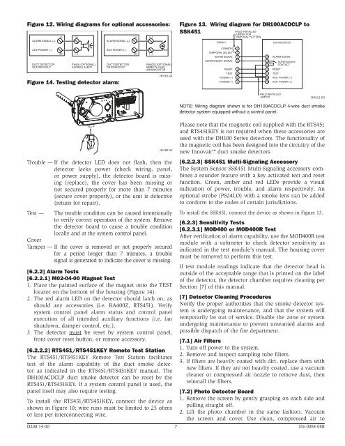
Figure 12. Wiring diagrams for optional accessories:<br />
15 (+)<br />
15 (+)<br />
ALARM SIGNAL (+)<br />
ALARM SIGNAL (+)<br />
Figure 13. Wiring diagram for <strong>DH100ACDCLP</strong> to<br />
SSK451<br />
SSK451<br />
FIELD INSTALLED<br />
JUMPER FOR<br />
TEMPORAL PATTERN<br />
<strong>DH100ACDCLP</strong><br />
AUX POWER (–)<br />
DUCT DETECTOR<br />
<strong>DH100ACDCLP</strong><br />
20<br />
(–)<br />
PA400 (OPTIONAL)<br />
AUDIBLE ALERT<br />
AUX POWER (–)<br />
DUCT DETECTOR<br />
<strong>DH100ACDCLP</strong><br />
Figure 14. Testing <strong>detector</strong> alarm:<br />
20<br />
(–)<br />
RED<br />
RA400Z (OPTIONAL)<br />
REMOTE (LED)<br />
ANNUNCIATOR<br />
H0161-00<br />
COMMON 3<br />
TEMPORAL SELECT 2<br />
ALARM SIGNAL 1<br />
SUPERVISORY SIGNAL 4<br />
RESET 7<br />
TEST 8<br />
POWER (–) 6<br />
POWER (+) 5<br />
15 ALARM SIGNAL<br />
3<br />
NO<br />
14<br />
2 RESET<br />
11 TEST<br />
SUPERVISORY<br />
CONTACT<br />
20 AUX. POWER (–)<br />
19 AUX. POWER (+)<br />
FIELD INSTALLED<br />
JUMPER<br />
H0162-00<br />
H0160-00<br />
Trouble — If the <strong>detector</strong> LED does not flash, then the<br />
<strong>detector</strong> lacks power (check wiring, panel,<br />
or power supply), the <strong>detector</strong> board is missing<br />
(replace), the cover has been missing or<br />
not secured properly for more than 7 minutes<br />
(secure cover properly), or the unit is defective<br />
(return for repair).<br />
Test — The trouble condition can be caused intentionally<br />
to verify correct operation of the system. Remove<br />
the <strong>detector</strong> board to cause a trouble condition<br />
locally and at the system control panel.<br />
Cover<br />
Tamper — If the cover is removed or not properly secured<br />
for a period longer than 7 minutes, a trouble<br />
signal is generated to indicate the cover is missing.<br />
[6.2.2] Alarm Tests<br />
[6.2.2.1] M02-04-00 Magnet Test<br />
1. Place the painted surface of the magnet onto the TEST<br />
locator on the bottom of the housing (Figure 14).<br />
2. The red alarm LED on the <strong>detector</strong> should latch on, as<br />
should any accessories (i.e. RA400Z, RTS451). Verify<br />
system control panel alarm status and control panel<br />
execution of all intended auxiliary functions (i.e. fan<br />
shutdown, damper control, etc.).<br />
3. The <strong>detector</strong> must be reset by system control panel,<br />
front cover reset button, or remote accessory.<br />
[6.2.2.2] RTS451/RTS451KEY Remote Test Station<br />
The RTS451/RTS451KEY Remote Test Station facilitates<br />
test of the alarm capability of the duct <strong>smoke</strong> <strong>detector</strong><br />
as indicated in the RTS451/RTS451KEY manual. The<br />
<strong>DH100ACDCLP</strong> duct <strong>smoke</strong> <strong>detector</strong> can be reset by the<br />
RTS451/RTS451KEY. If a system control panel is used, the<br />
panel itself may also require testing.<br />
To install the RTS451/RTS451KEY, connect the device as<br />
shown in Figure 10; wire runs must be limited to 25 ohms<br />
or less per interconnecting wire.<br />
NOTE: Wiring diagram shown is for <strong>DH100ACDCLP</strong> 4-wire duct <strong>smoke</strong><br />
<strong>detector</strong> system equipped without a control panel.<br />
Please note that the magnetic coil supplied with the RTS451<br />
and RTS451KEY is not required when these accessories are<br />
used with the DH100 Series <strong>detector</strong>s. The functionality of<br />
the magnetic coil has been designed into the circuitry of the<br />
new <strong>Innovair</strong> duct <strong>smoke</strong> <strong>detector</strong>s.<br />
[6.2.2.3] SSK451 Multi-Signaling Accessory<br />
The System Sensor SSK451 Multi-Signaling accessory combines<br />
a sounder feature with a key activated test and reset<br />
function. Green, amber and red LEDs provide a visual<br />
indication of power, trouble, and alarm respectively. An<br />
optional strobe (PS24LO) with a <strong>smoke</strong> lens can be added<br />
to conform to the codes of certain jurisdictions.<br />
To install the SSK451, connect the device as shown in Figure 13.<br />
[6.2.3] Sensitivity Tests<br />
[6.2.3.1] MOD400 or MOD400R Test<br />
After verification of alarm capability, use the MOD400R test<br />
module with a voltmeter to check <strong>detector</strong> sensitivity as<br />
indicated in the test module’s manual. The housing cover<br />
must be removed to perform this test.<br />
If test module readings indicate that the <strong>detector</strong> head is<br />
outside of the acceptable range that is printed on the label<br />
of the <strong>detector</strong>, the <strong>detector</strong> chamber requires cleaning per<br />
Section [7] of this manual.<br />
[7] Detector Cleaning Procedures<br />
Notify the proper authorities that the <strong>smoke</strong> <strong>detector</strong> system<br />
is undergoing maintenance, and that the system will<br />
temporarily be out of service. Disable the zone or system<br />
undergoing maintenance to prevent unwanted alarms and<br />
possible dispatch of the fire department.<br />
[7.1] Air Filters<br />
1. Turn off power to the system.<br />
2. Remove and inspect sampling tube filters.<br />
3. If filters are heavily coated with dirt, replace them with<br />
new filters. If they are not heavily coated, use a vacuum<br />
cleaner or compressed air nozzle to remove dust, then<br />
reinstall the filters.<br />
[7.2] Photo Detector Board<br />
1. Remove the screen by gently grasping on each side and<br />
pulling straight off.<br />
2. Lift the photo chamber in the same fashion. Vacuum<br />
the screen and cover. Use clean, compressed air to<br />
D200-14-00 7 I56-0084-08R


