

VG2000 Series Cast Iron Flanged Globe Valves Product Bulletin
VG2000 Series Cast Iron Flanged Globe Valves Product Bulletin
VG2000 Series Cast Iron Flanged Globe Valves Product Bulletin
- No tags were found...

Create successful ePaper yourself
Turn your PDF publications into a flip-book with our unique Google optimized e-Paper software.
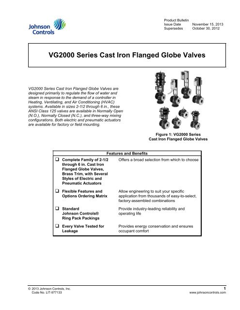
<strong>Product</strong> <strong>Bulletin</strong>Issue Date November 15, 2013Supersedes October 30, 2012<strong>VG2000</strong> <strong>Series</strong> <strong>Cast</strong> <strong>Iron</strong> <strong>Flanged</strong> <strong>Globe</strong> <strong>Valves</strong><strong>VG2000</strong> <strong>Series</strong> <strong>Cast</strong> <strong>Iron</strong> <strong>Flanged</strong> <strong>Globe</strong> <strong>Valves</strong> aredesigned primarily to regulate the flow of water andsteam in response to the demand of a controller inHeating, Ventilating, and Air Conditioning (HVAC)systems. Available in sizes 2-1/2 through 6 in., theseANSI Class 125 valves are available in Normally Open(N.O.), Normally Closed (N.C.), and three-way mixingconfigurations. Both electric and pneumatic actuatorsare available for factory or field mounting.Figure 1: <strong>VG2000</strong> <strong>Series</strong><strong>Cast</strong> <strong>Iron</strong> <strong>Flanged</strong> <strong>Globe</strong> <strong>Valves</strong>Features and Benefits Complete Family of 2-1/2 Offers a broad selection from which to choosethrough 6 in. <strong>Cast</strong> <strong>Iron</strong><strong>Flanged</strong> <strong>Globe</strong> <strong>Valves</strong>,Brass Trim, with SeveralStyles of Electric andPneumatic Actuators Flexible Features andOptions Ordering Matrix StandardJohnson Controls®Ring Pack Packings Every Valve Tested forLeakageAllow engineering to suit your specificapplication from thousands of easy-to-select,factory-assembled combinationsProvide industry-leading reliability andoperating lifeProvides energy conservation and ensuresoccupant comfort© 2013 Johnson Controls, Inc. 1Code No. LIT-977133www.johnsoncontrols.com
Table 1: Ordering Data — <strong>VG2000</strong> <strong>Series</strong> <strong>Cast</strong> <strong>Iron</strong> <strong>Flanged</strong> <strong>Globe</strong> <strong>Valves</strong>V GValve Global1 22 <strong>Product</strong> Family 2 = <strong>Cast</strong> <strong>Iron</strong>32 Body Type 2 = Two-Way, Normally Open/Push-Down-To-Close44 = Two-Way, Normally Closed/Push-Down-To-Open8 = Three-Way Mixing3 End 3 = ANSI Class 125 Flat-Faced <strong>Flanged</strong>5 Connections1 Trim and Flow 1 = Brass, Modified Linear6 CharacteristicsT Size and Cv Valve Two-Way Two-Way Three-Way7 (Kv = Cv x 0.857) Size N.O./PDTC N.C./PDTO MixingT = 2-1/2 in. 51.0 54.0 54.0U = 3 in. 83.0 83.0 80.0V = 4 in. 150.0 150.0 157.0W = 5 in. 240.0 237.0 238.0Y = 6 in. 350.0 344.0 347.0M Stem Type L = 3/8 in. Threaded Stem8 (2-1/2 and 3 in. N.O. <strong>Valves</strong> with MP82 Actuator Only)M = 3/8 in. Threaded Stem(2-1/2 through 4 in. <strong>Valves</strong> Only)N = 1/2 in. Threaded Stem(3 through 6 in. <strong>Valves</strong> Only)+ Actuator + = Factory-Mounted Actuator (See Tables 2 and 3.)9 Mounting (Leave fields 9 through 15 blank for valve without afactory-mounted actuator.)1 2 3 4 5 6 7 8 9 10 11 12 13 14 15 = FieldV G 2 2 3 1 T M + Example: <strong>Cast</strong> iron valve; two-way, normally open/push-down-to-close;Valve + Actuatorflat-faced flanged end connections; brass trim; modified linear;2-1/2 in.; 51.0 Cv, 3/8 in. threaded stem.Note: See Table 2 when adding a factory-mounted pneumatic actuator to a valve body. See Table 3 and Table 4when adding a factory-mounted electric actuator to a valve body. For valid actuator and valve combinations, see Table 5.2 <strong>VG2000</strong> <strong>Series</strong> <strong>Cast</strong> <strong>Iron</strong> <strong>Flanged</strong> <strong>Globe</strong> <strong>Valves</strong> <strong>Product</strong> <strong>Bulletin</strong>
Table 2: Ordering Data — Adding a Factory-Mounted Pneumatic ActuatorV G 2 2 3 1 T L + 8 2 MP8000 <strong>Series</strong> 82 = MP82, 25 sq. in., Spring-Return-Up1 2 3 4 5 6 7 8 9 10 11Pneumatic (2-1/2 and 3 in. N.O. <strong>Valves</strong> with “L” Stem)Actuator(See Actuator<strong>Product</strong> <strong>Bulletin</strong>.)84 = MP84, 50 sq. in., Spring-Return-Up(All 2-1/2 through 4 in. <strong>Valves</strong> with “M” Stem)86 = MP86, 100 sq. in., Spring-Return-Up(All 3 through 6 in. <strong>Valves</strong> with “N” Stem)(Note: Only spring-return-up models of MP8000 <strong>Series</strong> Actuators areavailable factory mounted to <strong>VG2000</strong> <strong>Series</strong> <strong>Cast</strong> <strong>Iron</strong> <strong>Valves</strong>.)3 Stroke 3 = 3/4 in. (2-1/2 and 3 in. <strong>Valves</strong> with MP82 or MP84 Actuators Only)12(MP8000 <strong>Series</strong>) 5 = 1-1/8 in. (3 and 4 in. <strong>Valves</strong> with MP84 or MP86 Actuators Only)7 = 1-1/2 in. (5 and 6 in. <strong>Valves</strong> with MP86 Actuator Only)C Spring Range C = 3 to 7 psig (Suggested for N.O. <strong>Valves</strong> with Positioner)13(MP8000 <strong>Series</strong>) D = 4 to 8 psig (Suggested for Three-Way <strong>Valves</strong> withPositioner)E = 9 to 13 psig (Suggested for N.C. <strong>Valves</strong> with Positioner)0 1 Accessories 00 = None14 15(MP8000 <strong>Series</strong>) 01 = V-9502 Pneumatic Positioner02 = EPP-1000 Electro-Pneumatic Positioner1 2 3 4 5 6 7 8 9 10 11 12 13 14 15 = FieldV G 2 2 3 1 T L + 8 2 3 C 0 1 Example: <strong>Cast</strong> iron valve; two-way, normally open; flat-faced flangedValve + Actuatorend connections; brass trim; modified linear; 2-1/2 in.; 51.0 Cv; 3/8 in.threaded stem; MP82 Pneumatic Actuator; 3/4 in. stroke; 3 to 7 psigspring range with factory-mounted V-9502 Positioner.Note: See Table 1 when ordering a valve body only. See Table 3 and Table 4 when adding a factory-mounted electricactuator to a valve body. For valid actuator and valve combinations, see Table 5 through Table 12.<strong>VG2000</strong> <strong>Series</strong> <strong>Cast</strong> <strong>Iron</strong> <strong>Flanged</strong> <strong>Globe</strong> <strong>Valves</strong> <strong>Product</strong> <strong>Bulletin</strong> 3
Table 3: Ordering Data — Adding a Factory-Mounted Electric ActuatorV G 2 2 3 1 U M 2 Factory + = Single Actuator1 2 3 4 5 6 7 8 9 Mounted 2 = Tandem Actuators (M9124-xGx-2 or M9220-xGx-3 only)Actuator(Tandem Actuators can only be factory mounted onVG2231UM, VG2231VM, VG2231WN, VG2231YNVG2831UM, VG2831VM, VG2831WN, VG2831YN<strong>Valves</strong> Only)9 2 6 M91xx/M9220 Non-Spring Return10 11 12<strong>Series</strong> Electric 916 = M9116-xGx-2 (VG2231TM and VG2831TM only)Actuator 924 = M9124-xGx-2(See Actuator<strong>Product</strong> <strong>Bulletin</strong>.)Spring Return92N = M9220-xGx-3 (Spring to Open, Stem Up)94N = M9220-xGx-3 (Spring to Close, Stem Down)A Control A = Floating, 24 VAC/VDC (M91xx and M9220)13 Type B = On/Off, 24 VAC/VDC (M9220 only)G Supply G = 24 VAC14 VoltageG = Proportional, 0-10 VDC or 0-20 mAC Feedback A = 0-10 VDC (Proportional only); No Feedback (All others)15C = 0-10 VDC (Proportional only); 2 Aux. Sw. (All Models)Note:When ordering Option “C” on tandemfactory mounted actuators, only oneactuator will have auxiliary switches.1 2 3 4 5 6 7 8 9 10 11 12 13 14 15 = FieldV G 2 2 3 1 U M 2 9 2 N A G C Example: <strong>Cast</strong> iron valve; two-way, push-down-to-close; flat-facedValve + Actuatorflanged end connections; brass trim; modified linear; 3 in.; 80.0 Cv;3/8 in. threaded stem with one Spring Return M9220-AGC-3Proportional Electric Actuator; 24 VAC supply; with two auxiliaryswitches; and one M9220-AGA-3 Spring Return Proportional ElectricActuator; 24 VAC supply without auxiliary switches.Note: See Table 1 when ordering a valve body only. See Table 2 when adding a factory-mounted pneumatic actuator to avalve body. For valid actuator and valve combinations, see Table 5 through Table 12.4 <strong>VG2000</strong> <strong>Series</strong> <strong>Cast</strong> <strong>Iron</strong> <strong>Flanged</strong> <strong>Globe</strong> <strong>Valves</strong> <strong>Product</strong> <strong>Bulletin</strong>
Table 4: Ordering Data — Adding a Factory-Mounted Electric ActuatorV G 2 2 3 1 T M + 3 0 VA-310x or Non-Spring Return1 2 3 4 5 6 7 8 9VA-610x <strong>Series</strong>Electric 30 = VA-310x (Available on 2-1/2 through 4 in. Two-Way PDTCActuatorand Three-Way Mixing <strong>Valves</strong> with “M” Stem, and 5 and 6 in.Two-Way PDTC and Three-Way Mixing <strong>Valves</strong> with “N”Stem)(See Actuator<strong>Product</strong>/Technical<strong>Bulletin</strong>.)60 = VA-610x (Available on 4 through 6 in. Two-Way PDTCand Three-Way Mixing <strong>Valves</strong> with “N” Stem)0 Actuator 0 = 2-1/2 in. <strong>Valves</strong> with 3/8 in. Threaded Stem12 Mounting 1 = 3 and 4 in. <strong>Valves</strong> with 3/8 in. Threaded Stem(VA-310x or 2 = 3 through 6 in. <strong>Valves</strong> with 1/2 in. Threaded StemVA-610x <strong>Series</strong>)A Actuator Input A = On/Off (Floating)13(VA-310x or H = Proportional, 0 to 10 VDCVA-610x <strong>Series</strong>)G Voltage G = 24 VAC14(VA-310x orVA-610x <strong>Series</strong>)C Accessories A = None (VA-310x <strong>Series</strong> Only)15(VA-310x or C = Two Auxiliary SwitchesVA-610x <strong>Series</strong>)1 2 3 4 5 6 7 8 9 10 11 12 13 14 15 = FieldV G 2 2 3 1 T M + 3 0 0 A G C Example: <strong>Cast</strong> iron valve; two-way, push-down-to-close; flat-facedValve + Actuatorflanged end connections; brass trim; modified linear; 2-1/2 in.; 51.0 Cv;3/8 in. threaded stem; VA-3100-AGC Non-Spring Return On/Off(Floating) Electric Actuator; 24 VAC supply with two auxiliary switches.Note: See Table 1 when ordering a valve body only. See Table 2 when adding a factory-mounted pneumatic actuator to avalve body. For valid actuator and valve combinations, see Table 5 through Table 12.<strong>VG2000</strong> <strong>Series</strong> <strong>Cast</strong> <strong>Iron</strong> <strong>Flanged</strong> <strong>Globe</strong> <strong>Valves</strong> <strong>Product</strong> <strong>Bulletin</strong> 5
Figure 2: VG2231 Two-Way Normally Open <strong>Valves</strong> with MP8000 <strong>Series</strong> Pneumatic Valve ActuatorsTable 5: VG2231 Two-Way Normally Open <strong>Valves</strong> with Pneumatic ActuatorsSpringRange3 to 7 psig 4 to 8 psig 9 to 13 psigSize,in.CvCloseoffpsigCode NumberCloseoffpsigCode NumberCloseoffpsigMP82 <strong>Series</strong> Actuators – 25 sq. in. Effective Diaphragm AreaCode Number2-1/2 51 53 VG2231TL+823C00 49 VG2231TL+823D00 28 VG2231TL+823E003 83 37 VG2231UL+823C00 34 VG2231UL+823D00 19 VG2231UL+823E00MP84 <strong>Series</strong> Actuators – 50 sq. in. Effective Diaphragm Area2-1/2 51 109 VG2231TM+843C00 100 VG2231TM+843D00 58 VG2231TM+843E003 83 75 VG2231UM+845C00 70 VG2231UM+845D00 40 VG2231UM+845E004 150 42 VG2231VM+845C00 39 VG2231VM+845D00 23 VG2231VM+845E00MP86 <strong>Series</strong> Actuators – 100 sq. in. Effective Diaphragm Area3 83 152 VG2231UN+865C00 140 VG2231UN+865D00 81 VG2231UN+865E004 150 86 VG2231VN+865C00 79 VG2231VN+865D00 46 VG2231VN+865E005 240 55 VG2231WN+867C00 51 VG2231WN+867D00 29 VG2231WN+867E006 350 38 VG2231YN+867C00 35 VG2231YN+867CD0 20 VG2231YN+867E00To add an optional positioner to the valve assembly, change the 00 at the end of the code number to 01 for a V-9502-95pneumatic positioner or to 02 for an EPP-1000-8 Electro-pneumatic positioner.Example: VG2231TM+843C01 for a V-9502-95 pneumatic positioner, orVG2231TM+843C02 for an EPP-1000-8 Electro-pneumatic positioner.6 <strong>VG2000</strong> <strong>Series</strong> <strong>Cast</strong> <strong>Iron</strong> <strong>Flanged</strong> <strong>Globe</strong> <strong>Valves</strong> <strong>Product</strong> <strong>Bulletin</strong>
Figure 3: VG2431 Two-Way Normally Closed <strong>Valves</strong> with MP8000 <strong>Series</strong> Pneumatic Valve ActuatorsTable 6: VG2431 Two-Way Normally Closed <strong>Valves</strong> with Pneumatic ActuatorsSpringRange3 to 7 psig 4 to 8 psig 9 to 13 psigSize,in.CvCloseoffpsigCode NumberCloseoffpsigCode NumberCloseoffpsigCode NumberMP84 <strong>Series</strong> Actuators – 50 sq. in. Effective Diaphragm Area2-1/2 54 24 VG2431TM+843C00 32 VG2431TM+843D00 75 VG2431TM+843E003 83 17 VG2431UM+845C00 22 VG2431UM+845D00 52 VG2431UM+845E004 150 9 VG2431VM+845C00 13 VG2431VM+845D00 29 VG2431VM+845E00MP86 <strong>Series</strong> Actuators – 100 sq. in. Effective Diaphragm Area3 83 34 VG2431UN+865C00 46 VG2431UN+865D00 105 VG2431UN+865E004 150 19 VG2431VN+865C00 26 VG2431VN+865D00 59 VG2431VN+865E005 237 12 VG2431WN+867C00 17 VG2431WN+867D00 38 VG2431WN+867E006 344 9 VG2431YN+867C00 11 VG2431YN+867D00 26 VG2431YN+867E00To add an optional positioner to the valve assembly, change the 00 at the end of the code number to 01 for a V-9502-95pneumatic positioner or to 02 for an EPP-1000-8 Electro-pneumatic positioner.Example: VG2431TM+843C01 for a V-9502-95 pneumatic positioner, orVG2431TM+843C02 for an EPP-1000-8 Electro-pneumatic positioner.<strong>VG2000</strong> <strong>Series</strong> <strong>Cast</strong> <strong>Iron</strong> <strong>Flanged</strong> <strong>Globe</strong> <strong>Valves</strong> <strong>Product</strong> <strong>Bulletin</strong> 7
Figure 4: VG2831 Three-Way Mixing Valve with MP8000 <strong>Series</strong> Pneumatic Valve ActuatorTable 7: VG2831 Three-Way Mixing <strong>Valves</strong> with Pneumatic ActuatorsSpringRange3 to 7 psig 4 to 8 psig 9 to 13 psigSize,in.CvCloseoffpsigCode NumberCloseoffpsigCode NumberCloseoffpsigCode NumberMP84 <strong>Series</strong> Actuators – 50 sq. in. Effective Diaphragm Area2-1/2 54 65/14 VG2831TM+843C00 60/19 VG2831TM+843D00 35/45 VG2831TM+843E003 83 45/10 VG2831UM+845C00 42/13 VG2831UM+845D00 24/31 VG2831UM+845E004 150 25/6 VG2831VM+845C00 23/8 VG2831VM+845D00 14/18 VG2831VM+845E00MP86 <strong>Series</strong> Actuators – 100 sq. in. Effective Diaphragm Area3 83 91/21 VG2831UN+865C00 84/28 VG2831UN+865D00 49/63 VG2831UN+865E004 150 51/12 VG2831VN+865C00 47/16 VG2831VN+865D00 27/35 VG2831VN+865E005 237 33/7 VG2831WN+867C00 30/10 VG2831WN+867D00 18/23 VG2831WN+867E006 344 23/5 VG2831YN+867C00 21/7 VG2831YN+867CD0 12/16 VG2831YN+867E00To add an optional positioner to the valve assembly, change the 00 at the end of the code number to 01 for a V-9502-95pneumatic positioner or to 02 for an EPP-1000-8 Electro-pneumatic positioner.Example: VG2831TM+843C01 for a V-9502-95 pneumatic positioner, orVG2831TM+843C02 for an EPP-1000-8 Electro-pneumatic positioner.8 <strong>VG2000</strong> <strong>Series</strong> <strong>Cast</strong> <strong>Iron</strong> <strong>Flanged</strong> <strong>Globe</strong> <strong>Valves</strong> <strong>Product</strong> <strong>Bulletin</strong>
Figure 5: VG2x31 <strong>Valves</strong> with M9220 <strong>Series</strong> Spring Return Electric Valve Actuators – No SwitchesTable 8: VG2x31 <strong>Valves</strong> with M9220-xGA-3 Actuators – Spring Return without SwitchesValveSize,in.CvCloseoffpsigFloating withoutSwitchesSpring ReturnOn/Off withoutSwitchesProportional withoutSwitchesM9220-AGA-3 M9220-BGA-3 M9220-GGA-3Two-Way – Spring Return Normally Open – Valve Stem UpVG2231TM 2-1/2 51 76 VG2231TM+92NAGA VG2231TM+92NBGA VG2231TM+92NGGAVG2231UM 3 83 33 VG2231UM+92NAGA VG2231UM+92NBGA VG2231UM+92NGGAVG2231UM 3 83 66 VG2231TM292NAGA* VG2231UM292NBGA* VG2231UM292NGGA*VG2231VM 4 150 37 VG2231UM292NAGA* VG2231VM292NBGA* VG2231VM292NGGA*VG2231WN 5 240 20 VG2231WN292NAGA* VG2231WN292NBGA* VG2231WN292NGGA*Two-Way – Spring Return Normally Closed – Valve Stem DownVG2231TM 2-1/2 51 76 VG2231TM+94NAGA VG2231TM+94NBGA VG2231TM+94NGGAVG2231UM 3 83 33 VG2231UM+94NAGA VG2231UM+94NBGA VG2231UM+94NGGAVG2231UM 3 83 66 VG2231TM294NAGA* VG2231UM294NBGA* VG2231UM294NGGA*VG2231VM 4 150 37 VG2231UM294NAGA* VG2231VM294NBGA* VG2231VM294NGGA*VG2231WN 5 240 20 VG2231WN294NAGA* VG2231WN294NBGA* VG2231WN294NGGA*Three-Way Mixing – Spring Return – Valve Stem Up – Side Inlet Port ClosedVG2831TM 2-1/2 54 45 VG2831TM+92NAGA VG2831TM+92NBGA VG2831TM+92NGGAVG2831UM 3 80 20 VG2831UM+92NAGA VG2831UM+92NBGA VG2831UM+92NGGAVG2831UM 3 80 40 VG2831UM292NAGA* VG2831UM292NBGA* VG2831UM292NGGA*VG2831VM 4 157 11 VG2831VM+92NAGA VG2831VM+92NBGA VG2831VM+92NGGAVG2831VM 4 157 22 VG2831VM292NAGA* VG2831VM292NBGA* VG2831VM292NGGA*VG2831WN 5 238 12 VG2831WM292NAGA* VG2831WN292NBGA* VG2831WN292NGGA*VG2831YN 6 347 7 VG2831YN292NAGA* VG2831YN292NBGA* VG2831YN292NGGA*Three-Way Mixing – Spring Return – Valve Stem Down – Side Inlet Port OpenVG2831TM 2-1/2 54 45 VG2831TM+94NAGA VG2831TM+94NBGA VG2831TM+94NGGAVG2831UM 3 80 20 VG2831UM+94NAGA VG2831UM+94NBGA VG2831UM+94NGGAVG2831UM 3 80 40 VG2831UM294NAGA* VG2831UM294NBGA* VG2831UM294NGGA*VG2831VM 4 157 11 VG2831VM+92NAGA VG2831VM+94NBGA VG2831VM+94NGGAVG2831VM 4 157 22 VG2831VM294NAGA* VG2831VM294NBGA* VG2831VM294NGGA*VG2831WN 5 238 12 VG2831WM294NAGA* VG2831WN294NBGA* VG2831WN294NGGA*VG2831YN 6 347 7 VG2831YN294NAGA* VG2831YN294NBGA* VG2831YN294NGGA** Valve assemblies require two actuators mounted in tandem.<strong>VG2000</strong> <strong>Series</strong> <strong>Cast</strong> <strong>Iron</strong> <strong>Flanged</strong> <strong>Globe</strong> <strong>Valves</strong> <strong>Product</strong> <strong>Bulletin</strong> 9
Figure 6: VG2x31 <strong>Valves</strong> with M9220 <strong>Series</strong> Spring Return Electric Valve Actuators – with SwitchesTable 9: VG2x31 <strong>Valves</strong> with M9220-xGC-3 Actuators – Spring Return with SwitchesSpring ReturnFloating with TwoSwitchesOn/Off with TwoSwitchesProportional with TwoSwitchesValve Size, Cv Closeoff M9220-AGC-3 M9220-BGC-3 M9220-GGC-3in.psigTwo-Way – Spring Return Normally Open – Valve Stem UpVG2231TM 2-1/2 51 76 VG2231TM+92NAGC VG2231TM+92NBGC VG2231TM+92NGGCVG2231UM 3 83 33 VG2231UM+92NAGC VG2231UM+92NBGC VG2231UM+92NGGCVG2231UM 3 83 66 VG2231TM292NAGC* VG2231UM292NBGC* VG2231UM292NGGC*VG2231VM 4 150 37 VG2231UM292NAGC* VG2231VM292NBGC* VG2231VM292NGGC*VG2231WN 5 240 20 VG2231WN292NAGC* VG2231WN292NBGC* VG2231WN292NGGC*Two-Way – Spring Return Normally Closed – Valve Stem DownVG2231TM 2-1/2 51 76 VG2231TM+94NAGC VG2231TM+94NBGC VG2231TM+94NGGCVG2231UM 3 83 33 VG2231UM+94NAGC VG2231UM+94NBGC VG2231UM+94NGGCVG2231UM 3 83 66 VG2231TM294NAGC* VG2231UM294NBGC* VG2231UM294NGGC*VG2231VM 4 150 37 VG2231UM294NAGC* VG2231VM294NBGC* VG2231VM294NGGC*VG2231WN 5 240 20 VG2231WN294NAGC* VG2231WN294NBGC* VG2231WN294NGGC*Three-Way Mixing – Spring Return – Valve Stem UpVG2831TM 2-1/2 54 45 VG2831TM+92NAGC VG2831TM+92NBGC VG2831TM+92NGGCVG2831UM 3 80 20 VG2831UM+92NAGC VG2831UM+92NBGC VG2831UM+92NGGCVG2831UM 3 80 40 VG2831UM292NAGC* VG2831UM292NBGC* VG2831UM292NGGC*VG2831VM 4 157 11 VG2831VM+92NAGC VG2831VM+92NBGC VG2831VM+92NGGCVG2831VM 4 157 22 VG2831VM292NAGC* VG2831VM292NBGC* VG2831VM292NGGC*VG2831WN 5 238 12 VG2831WM292NAGC* VG2831WN292NBGC* VG2831WN292NGGC*VG2831YN 6 347 7 VG2831YN292NAGC* VG2831YN292NBGC* VG2831YN292NGGC*Three-Way Mixing – Spring Return – Valve Stem DownVG2831TM 2-1/2 54 45 VG2831TM+94NAGC VG2831TM294NBGC VG2831TM294NGGCVG2831UM 3 80 20 VG2831UM+94NAGC VG2831UM294NBGC VG2831UM294NGGCVG2831UM 3 80 40 VG2831UM294NAGC* VG2831UM294NBGC* VG2831UM294NGGC*VG2831VM 4 157 11 VG2831VM+94NAGC VG2831VM+94NBGC VG2831VM+94NGGCVG2831VM 4 157 22 VG2831VM294NAGC* VG2831VM294NBGC* VG2831VM294NGGC*VG2831WN 5 238 12 VG2831WM294NAGC* VG2831WN294NBGC* VG2831WN294NGGC*VG2831YN 6 347 7 VG2831YN294NAGC* VG2831YN294NBGC* VG2831YN294NGGC** Valve assemblies require two actuators mounted in tandem. On tandem assemblies with switches, only one actuator isrequired to have switches.10 <strong>VG2000</strong> <strong>Series</strong> <strong>Cast</strong> <strong>Iron</strong> <strong>Flanged</strong> <strong>Globe</strong> <strong>Valves</strong> <strong>Product</strong> <strong>Bulletin</strong>
Figure 7: VG2x31 <strong>Valves</strong> with M91xx <strong>Series</strong> Non-Spring Return Electric Valve ActuatorsTable 10: VG2x31 <strong>Valves</strong> with M91xx-xGx-2 Actuators – Non-Spring ReturnNon-Spring ReturnOn/Off Floatingwithout SwitchesProportionalwithout SwitchesOn/Off Floatingwith TwoSwitchesProportional withTwo SwitchesSize,in.CvCloseoffpsigM9116-AGA-2M9124-AGA-2M9116-GGA-2M9124-GGA-2Two-Way, Push-Down-To-CloseM9116-AGC-2M9124-AGC-2M9116-GGC-2M9124-GGC-22-1/2 51 62 VG2231TM+916AGA VG2231TM+916GGA VG2231TM+916AGC VG2231TM+916GGC2-1/2 51 101 VG2231TM+924AGA VG2231TM+924GGA VG2231TM+924AGC VG2231TM+924GGC3 83 27 VG2231UM+916AGA VG2231UM+916GGA VG2231UM+916AGC VG2231UM+916GGC3 83 43 VG2231UM+924AGA VG2231UM+924GGA VG2231UM+924AGC VG2231UM+924GGC3 83 88 VG2231UM2924AGA* VG2231UM2924GGA* VG2231UM2924AGC* VG2231UM2924GGC*4 150 24 VG2231VM+924AGA VG2231VM+924GGA VG2231VM+924AGC VG2231VM+924GGC4 150 49 VG2231VM2924AGA* VG2231VM2924GGA* VG2231VM2924AGC* VG2231VM2924GGC*5 240 26 VG2231WN2924AGA* VG2231WN2924GGA* VG2231WN2924AGC* VG2231WN2924GGC*6 350 16 VG2231YN2924AGA* VG2231YN2924GGA* VG2231YN2924AGC* VG2231YN2924GGC*Three-Way, Mixing2-1/2 54 37 VG2831TM+916AGA VG2831TM+916GGA VG2831TM+916AGC VG2831TM+916GGC2-1/2 54 60 VG2831TM+924AGA VG2831TM+924GGA VG2831TM+924AGC VG2831TM+924GGC3 80 16 VG2831UM+916AGA VG2831UM+916GGA VG2831UM+916AGC VG2831UM+916GGC3 80 26 VG2831UM+924AGA VG2831UM+924GGA VG2831UM+924AGC VG2831UM+924GGC3 80 53 VG2831UM2924AGA* VG2831UM2924GGA* VG2831UM2924AGC* VG2831UM2924GGC*4 157 9 VG2831VM+916AGA VG2831VM+916GGA VG2831VM+916AGC VG2831VM+916GGC4 157 14 VG2831VM+924AGA VG2831VM+924GGA VG2831VM+924AGC VG2831VM+924GGC4 157 30 VG2831VM2924AGA* VG2831VM2924GGA* VG2831VM2924AGC* VG2831VM2924GGC*5 238 7 VG2831WN+924AGA VG2831WN+924GGA VG2831WN+924AGC VG2831WN+924GGC5 238 15 VG2831WN2924AGA* VG2831WN2924GGA* VG2831WN2924AGC* VG2831WN2924GGC*6 347 4 VG2831YN+924AGA VG2831YN+924GGA VG2831YN+924AGC VG2831YN+924GGC6 347 9 VG2831YN2924AGA* VG2831YN2924GGA* VG2831YN2924AGC* VG2831YN2924GGC** Valve assemblies require two actuators mounted in tandem. On tandem assemblies with switches, only one actuator isrequired to have switches. M9116-AGx-2 actuators are not designed for tandem operation.<strong>VG2000</strong> <strong>Series</strong> <strong>Cast</strong> <strong>Iron</strong> <strong>Flanged</strong> <strong>Globe</strong> <strong>Valves</strong> <strong>Product</strong> <strong>Bulletin</strong> 11
Figure 8: VG2x31 <strong>Valves</strong> with VA-3100 <strong>Series</strong> Non-Spring Return Electric Valve ActuatorsTable 11: VG2x31 <strong>Valves</strong> with VA-3100-xGx <strong>Series</strong> Non-Spring Return ActuatorsNon-Spring ReturnOn/Off Floatingwithout SwitchesOn/Off Floatingwith Two SwitchesProportional with TwoSwitchesValveSize,in.CvCloseoffpsigVA-3100-AGA VA-3100-AGC VA-3100-HGCTwo-Way Push-Down-To-CloseVG2231TM 2-1/2 51 115 VG2231TM+300AGA VG2231TM+300AGC VG2231TM+300HGCVG2231UM 3 83 79 VG2231UM+301AGA VG2231UM+301AGC VG2231UM+301HGCVG2231VM 4 150 45 VG2231VM+301AGA VG2231VM+301AGC VG2231VM+301HGCVG2231WN 5 240 29 VG2231WN+302AGA VG2231WN+302AGC VG2231WN+302HGCVG2231YN 6 350 20 VG2231YN+302AGA VG2231YN+302AGC VG2231YN+302HGCThree-Way MixingVG2831TM 2-1/2 54 69 VG2831TM+300AGA VG2831TM+300AGC VG2831TM+300HGCVG2831UM 3 80 48 VG2831UM+301AGA VG2831UM+301AGC VG2831UM+301HGCVG2831VM 4 157 27 VG2831VM+301AGA VG2831VM+301AGC VG2831VM+301HGCVG2831WN 5 238 17 VG2831WN+302AGA VG2831WN+302AGC VG2831WN+302HGCVG2831YN 6 347 12 VG2831YN+302AGA VG2831YN+302AGC VG2831YN+302HGC12 <strong>VG2000</strong> <strong>Series</strong> <strong>Cast</strong> <strong>Iron</strong> <strong>Flanged</strong> <strong>Globe</strong> <strong>Valves</strong> <strong>Product</strong> <strong>Bulletin</strong>
Application Overview<strong>VG2000</strong> <strong>Series</strong> <strong>Cast</strong> <strong>Iron</strong> <strong>Flanged</strong> <strong>Globe</strong> <strong>Valves</strong>feature brass trim and are available in two-wayPush-Down-To-Close ([PDTC] – normally open ifpneumatically actuated) or Push-Down-To-Open([PDTO] – normally closed if pneumatically actuated)and three-way mixing configurations. These ironvalves can be ordered with MP8000 <strong>Series</strong> PneumaticActuators (with or without a factory-mountedpneumatic or electro-pneumatic positioner). <strong>VG2000</strong><strong>Series</strong> <strong>Valves</strong> can also be ordered with any of thefollowing series of electric actuators: M9116, M9124,M9220, VA-310x, or VA-610x. All electric actuators arefully compatible with Johnson Controls controllers,reducing installation costs. <strong>Valves</strong> without actuatorscan be ordered with the standard bonnet and stemdesign, allowing easy interchangeability of actuatorswith the use of standardized mounting kits. See Tables1, 2, 3, and 4 for ordering data and additional details.For valid valve and actuator combinations, see Tables5 through 12.The modulating valve plug of <strong>VG2000</strong> <strong>Series</strong> <strong>Valves</strong>provides a modified linear flow characteristic. An arrowis cast on both sides of the valve body indicating thedirection of flow for proper piping.Pneumatic Actuator Selection(See Tables 1 and 2.)MP8000 <strong>Series</strong> Pneumatic ActuatorsThe MP82 (25 sq. in. effective diaphragm area),MP84 (50 sq. in. effective diaphragm area), andMP86 (100 sq. in. effective diaphragm area) areequipped with a molded synthetic rubber diaphragmcontained in a sturdy, carbon-steel housing thatprotects it against dirt and damage. The actuator canbe easily removed to perform inline servicing to allparts of the valve. MP8000 <strong>Series</strong> PneumaticActuators are available factory mounted or are easilyfield mounted to <strong>VG2000</strong> <strong>Series</strong> <strong>Valves</strong>.MP8000 <strong>Series</strong> Pneumatic Actuators are designed toallow for reversing the action of each actuator in thefield. If desired, the action of the MP8000 <strong>Series</strong>Actuator can be reversed from spring-return-up tospring-return-down or vice versa. For instructions onfield reversing the action, refer to the MP8000 <strong>Series</strong>Pneumatic Valve Actuators Technical <strong>Bulletin</strong>(LIT-977258). The V-9502 Pneumatic Positioner andthe EPP-1000 Electro-Pneumatic Positioner are alsoavailable for factory or field mounting to MP8000<strong>Series</strong> Pneumatic Valve Actuators.Electric Actuator Selection(See Tables 1, 3, and 4.)Factory-mounted electric actuators are available ontwo-way PDTC and three-way mixing valveconfigurations only. These same actuators can be fieldmounted on PDTO valves if desired. All electricactuators used with <strong>VG2000</strong> <strong>Series</strong> <strong>Cast</strong> <strong>Iron</strong> Flange<strong>Globe</strong> <strong>Valves</strong> can be easily field reversed if required.All proportional electrically actuated assemblies arefactory calibrated for nominal 0 to 10 VDC operation todrive down with an increase in signal.M9100 <strong>Series</strong> Electric ActuatorsThe M9100 <strong>Series</strong> is a line of motor driven, non-springreturn actuators that operate on 24 VAC or VDCpower and are available for use with floating orproportional controllers. When coupled with theM9000-53x <strong>Series</strong> of Valve Linkages, the rotarymotion of this actuator is converted into linear motionthat operates 2-1/2 through 6 in. <strong>VG2000</strong> <strong>Series</strong><strong>Valves</strong>. Integral auxiliary switches are available forindicating end-stop position or performing switchingfunctions. Position feedback is available via switches,or a 0 to 10 VDC signal. For more information onM91xx <strong>Series</strong> Electric Actuators, refer to the M9108,M9116, M9124, and M9132 <strong>Series</strong> Electric Non-springReturn Actuators <strong>Product</strong> <strong>Bulletin</strong> (LIT-2681058).M9220 <strong>Series</strong> Electric ActuatorsThe M9220 <strong>Series</strong> is a line of motor driven, springreturn actuators that operate on 24 VAC or VDCpower and are available for use with on/off, floating, orproportional controllers. The 120 and 230 VAC modelsare available for field mounting for use with on/offcontrollers. When coupled with the M9000-53x <strong>Series</strong>of Valve Linkages, the rotary motion of this actuator isconverted into linear motion that operates 2-1/2through 6 in. <strong>VG2000</strong> <strong>Series</strong> <strong>Valves</strong>. Integral auxiliaryswitches are available for indicating end-stop positionor performing switching functions. Position feedback isavailable via switches or a 0 to 10 VDC signal. Formore information on M9220 <strong>Series</strong> Electric Actuators,refer to the M9220-xxx-3 Electric Spring ReturnActuators <strong>Product</strong> <strong>Bulletin</strong> (LIT-12011057).<strong>VG2000</strong> <strong>Series</strong> <strong>Cast</strong> <strong>Iron</strong> <strong>Flanged</strong> <strong>Globe</strong> <strong>Valves</strong> <strong>Product</strong> <strong>Bulletin</strong> 15
VA-310x <strong>Series</strong> Electric ActuatorsThe VA-310x <strong>Series</strong> uses a synchronous motor toaccurately position valves in HVAC and industrialapplications. This non-spring return actuator has a675 lb (3,000 N) force output for on/off (floating) orproportional control. Integral auxiliary switches areavailable for indicating end-stop position or performingswitching functions.For more information on VA-310x <strong>Series</strong> ElectricActuators, refer to the VA-3100 <strong>Series</strong> Electric ValveActuators <strong>Product</strong> <strong>Bulletin</strong> (LIT-977283).VA-610x <strong>Series</strong> Electric ActuatorsThe VA-610x <strong>Series</strong> uses a synchronous motor toaccurately position valves in HVAC and industrialapplications. This non-spring return actuator has a1,350 lb (6,000 N) force output for on/off (floating) orproportional control. Integral auxiliary switches areavailable for indicating end-stop position or performingswitching functions.For more information on VA-610x <strong>Series</strong> ElectricActuators, refer to the VA-6100 <strong>Series</strong> Electric ValveActuators <strong>Product</strong> <strong>Bulletin</strong> (LIT-977284).Table 16: Mounting Kits for Field Mounting M91xx and M9220 <strong>Series</strong> Electric ActuatorsMounting KitCode NumberValve Valve Size Valve StrokeStem Type(Diameter)M9000-530 VG2x31TM 2-1/2 in. 3/4 in “M” Stem (3/8 in.) SingleM9000-531M9000-532VG2x31UM andVG2x31VMVG2x31UM andVG2x31VM3 and 4 in. 1-1/8 in. “M” Stem (3/8 in.) Single3 and 4 in. 1-1/8 in. “M” Stem (3/8 in.) DualM9000-533 VG2x31WN 5 in. 1-3/8 in. “N” Stem (1/2 in.) SingleM9000-534 VG2x31WN 5 in. 1-3/8 in. “N” Stem (1/2 in.) DualM9000-535 VG2x31YN 6 in. 1-1/2 in. “N” Stem (1/2 in.) SingleM9000-536 VG2x31YN 6 in. 1-1/2 in. “N” Stem (1/2 in.) DualM9000-537VG2x31UN andVG2x31VN3 and 4 in. 1-1/8 in. “N” Stem (1/2 in.) DualNumber ofActuator(s)16 <strong>VG2000</strong> <strong>Series</strong> <strong>Cast</strong> <strong>Iron</strong> <strong>Flanged</strong> <strong>Globe</strong> <strong>Valves</strong> <strong>Product</strong> <strong>Bulletin</strong>
Table 17: Mounting Kits for Field Mounting MP8000 <strong>Series</strong> Pneumatic Valve ActuatorsMounting Kit CodeNumberActuator Style Valve Size Stem Type (Diameter)MP8000-6201 MP82/MP83/MP84/MP85 2-1/2 through 4 in. “L” Stem (3/8 in.) or“M” Stem (3/8 in.)MP8000-6203 MP86/MP87 3 through 6 in. “N” Stem (1/2 in.)Table 18: Mounting Kits for Field Mounting VA-310x <strong>Series</strong> Electric Valve ActuatorsMounting Kit Code Number Valve Size Stem Type (Diameter)VA-3100-500 2-1/2 through 4 in. “M” Stem (3/8 in.)VA-3100-501 5 and 6 in. “N” Stem (1/2 in.)Table 19: Mounting Kits for Field Mounting VA-610x <strong>Series</strong> Electric Valve ActuatorsMounting Kit Code Number Valve Size Stem Type (Diameter)VA-3100-501 4 through 6 in. “N” Stem (1/2 in.)<strong>VG2000</strong> <strong>Series</strong> <strong>Cast</strong> <strong>Iron</strong> <strong>Flanged</strong> <strong>Globe</strong> <strong>Valves</strong> <strong>Product</strong> <strong>Bulletin</strong> 17
Table 20: Maximum Closeoff Pressures, psig (kPa) for Factory-Assembled Pneumatically ActuatedTwo-Way <strong>Valves</strong>ActuatorStyleMP82MP84MP86ValveSizein.3 to 7(21 to 48)Two-Way N.O.(with 20 psig Supply)Spring Range, psig (kPa)*4 to 8(28 to 55)9 to 13(62 to 90)3 to 7(21 to 48)Two-Way N.C.(with 0 psig Supply)Spring Range, psig (kPa)*4 to 8(28 to 55)9 to 13(62 to 90)2-1/2 53 (365) 49 (338) 28 (193) --- --- ---3 37 (255) 34 (234) 19 (131) --- --- ---2-1/2 109 (751) 100 (689) 58 (400) 24 (165) 32 (220) 75 (517)3 75 (517) 70 (482) 40 (276) 17 (117) 22 (152) 52 (358)4 42 (289) 39 (269) 23 (158) 9 (62) 13 (90) 29 (200)3 152 (1,047) 140 (965) 81 (558) 34 (234) 46 (317) 105 (723)4 86 (592) 79 (544) 46 (317) 19 (131) 26 (179) 59 (407)5 55 (379) 51 (351) 29 (200) 12 (83) 17 (117) 38 (262)6 38 (262) 35 (241) 20 (138) 9 (62) 11 (76) 26 (179)* To maximize closeoff, the recommended spring ranges for use with a positioner are 3 to 7 psig (21 to 48 kPa) fortwo-way N.O. valves and 9 to 13 psig (62 to 90 kPa) for two-way N.C. valves.Note: The maximum fluid temperature is 281F (138C) water or 35 psig (241 kPa) saturated steam.Table 21: Maximum Closeoff Pressures, psig (kPa) for Factory-Assembled Pneumatically ActuatedThree-Way Mixing <strong>Valves</strong>ActuatorStyleMP84MP86ValveSize in.Three-Way Mixing N.O. Port(with 20 psig Supply)Spring Range, psig (kPa)*3 to 7(21 to 48)4 to 8(28 to 55)9 to 13(62 to 90)3 to 7(21 to 48)Three-Way Mixing N.C. Port(with 0 psig Supply)Spring Range, psig (kPa)*4 to 8(28 to 55)9 to 13(62 to 90)2-1/2 65 (448) 60 (413) 35 (241) 14 (96) 19 (131) 45 (310)3 45 (310) 42 (289) 24 (165) 10 (69) 13 (90) 31 (214)4 25 (172) 23 (158) 14 (96) 6 (41) 8 (55) 18 (124)3 91 (627) 84 (579) 49 (338) 21 (145) 28 (193) 63 (434)4 51 (351) 47 (324) 27 (186) 12 (83) 16 (110) 35 (241)5 33 (227) 30 (207) 18 (124) 7 (48) 10 (69) 23 (158)6 23 (158) 21 (145) 12 (83) 5 (34) 7 (48) 16 (110)* To maximize closeoff, the recommended spring range for use with a positioner is 4 to 8 psig (28 to 55 kPa) forthree-way mixing valves.Note: The maximum fluid temperature is 281F (138C) water or 35 psig (241 kPa) saturated steam.18 <strong>VG2000</strong> <strong>Series</strong> <strong>Cast</strong> <strong>Iron</strong> <strong>Flanged</strong> <strong>Globe</strong> <strong>Valves</strong> <strong>Product</strong> <strong>Bulletin</strong>
Table 22: Maximum Closeoff Pressures, psig (kPa) for Factory-Assembled Electrically Actuated Two-Wayand Three-Way <strong>Valves</strong>Valve Size, in.Actuator 2-1/2 3 4 5 6Two-Way, Push-Down-To-CloseM9116 62 (427) 27 (186) --- --- ---M9124 101 (696) 43 (296) 24 (165) --- ---M9124 (Tandem) --- 88 (606) 49 (337) 26 (179) 16 (110)M9220 76 (524) 33 (227) --- --- ---M9220 (Tandem) --- 66 (456) 37 (255) 20 (138) ---VA-3100 115 (792) 79 (544) 45 (310) 29 (200) 20 (138)VA-6100 --- --- 89 (613) 57 (393) 40 (276)Three-Way, MixingM9116 37 (255) 16 (110) 9 (62) --- ---M9124 60 (413) 26 (179) 14 (96) 7 (48) 4 (28)M9124 (Tandem) --- 53 (365) 30 (206) 15 (103) 9 (62)M9220 45 (310) 20 (138) 11 (76) --- ---M9220 (Tandem) --- 40 (276) 22 (152) 12 (83) 7 (48)Note:VA-3100 69 (475) 48 (331) 27 (186) 17 (117) 12 (83)VA-6100 --- --- 54 (372) 34 (234) 24 (165)The maximum fluid temperature is 281F (138C) water or 35 psig (241 kPa) saturated steam.<strong>VG2000</strong> <strong>Series</strong> <strong>Cast</strong> <strong>Iron</strong> <strong>Flanged</strong> <strong>Globe</strong> <strong>Valves</strong> <strong>Product</strong> <strong>Bulletin</strong> 19
EEAADBDBCMP82/84 ActuatedCMP86 ActuatedFigure 10: MP8000 Actuated Two-Way N.O. Valve Dimensions(See Table 23)Table 23: MP8000 Actuated Two-Way N.O. Valve Dimensions, in. (mm)ActuatorStyle*MP82MP84MP86Valve Size,in. A B C D E2-1/2 15-3/16 (386) 4-21/32 (118) 7-1/4 (184) 7 (178) 8-21/32 (220)3 15-13/16 (402) 5-3/16 (132) 8-5/8 (219) 7-1/2 (191) 8-21/32 (220)2-1/2 18-17/32 (471) 4-21/32 (118) 7-1/4 (184) 7 (178) 10-7/8 (276)3 19-3/16 (487) 5-5/16 (135) 8-5/8 (219) 7-1/2 (191) 10-7/8 (276)4 20-5/16 (516) 6-7/16 (164) 10-1/2 (267) 9 (229) 10-7/8 (276)3 27-1/4 (692) 5-5/16 (135) 8-5/8 (219) 7-1/2 (191) 10-7/8 (276)4 28-3/8 (721) 6-7/16 (164) 10-1/2 (267) 9 (229) 10-7/8 (276)5 28-13/16 (732) 6-7/8 (175) 12-1/2 (318) 10 (254) 10-7/8 (276)6 30-1/8 (765) 8-3/16 (208) 14-1/2 (368) 11 (279) 10-7/8 (276)* Allow 3-3/4 in. (95 mm) clearance for MP82/MP84 actuator removal and 4-3/4 in. (121 mm) clearance forMP86 actuator removal.20 <strong>VG2000</strong> <strong>Series</strong> <strong>Cast</strong> <strong>Iron</strong> <strong>Flanged</strong> <strong>Globe</strong> <strong>Valves</strong> <strong>Product</strong> <strong>Bulletin</strong>
FFAADBDBEECCMP84 Actuated MP86 ActuatedFigure 11: MP8000 Actuated Two-Way N.C. Valve Dimensions(See Table 24)Table 24: MP8000 Actuated Two-Way N.C. Valve Dimensions, in. (mm)ActuatorStyle*MP84MP86ValveSize,in.A B C D E F2-1/2 18-17/32 (471) 4-21/32 (118) 7-1/4 (184) 7 (178) 4-21/32 (118) 10-7/8 (276)3 19-3/16 (487) 5-5/16 (135) 8-5/8 (219) 7-1/2 (191) 5-5/16 (135) 10-7/8 (276)4 20-5/16 (516) 6-1/16 (152) 10-1/2 (267) 9 (229) 6-1/16 (152) 10-7/8 (276)3 27-1/4 (692) 5-5/16 (135) 8-5/8 (219) 7-1/2 (191) 5-5/16 (135) 10-7/8 (276)4 28-3/8 (721) 6-7/16 (164) 10-1/2 (267) 9 (229) 6-7/16 (164) 10-7/8 (276)5 28-13/16 (732) 6-7/8 (175) 12-1/2 (318) 10 (254) 6-7/8 (175) 10-7/8 (276)6 30-1/8 (765) 8-3/16 (208) 14-1/2 (368) 11 (279) 8-3/16 (208) 10-7/8 (276)* Allow 3-3/4 in. (95 mm) clearance for MP84 actuator removal and 4-3/4 in. (121 mm) clearance for MP86 actuatorremoval.<strong>VG2000</strong> <strong>Series</strong> <strong>Cast</strong> <strong>Iron</strong> <strong>Flanged</strong> <strong>Globe</strong> <strong>Valves</strong> <strong>Product</strong> <strong>Bulletin</strong> 21
FFAABBDEECCMP84 ActuatedMP86 ActuatedFigure 12: MP8000 Actuated Three-Way Mixing Valve Dimensions(See Table 25)Table 25: MP8000 Actuated Three-Way Mixing Valve Dimensions, in. (mm)ActuatorStyle*ValveSize,in.A B C D E FMP84 2-1/2 18-17/32 (471) 4-21/32 (118) 7-1/4 (184) 7 (178) 6-25/32 (172) 10-7/8 (276)3 19-3/16 (487) 5-5/16 (135) 8-5/8 (219) 7-1/2 (191) 6-13/16 (173) 10-7/8 (276)4 20-5/16 (516) 6-7/16 (164) 10-1/2 (267) 9 (229) 8-1/16 (205) 10-7/8 (276)MP86 3 27-1/4 (692) 5-5/16 (135) 8-5/8 (219) 7-1/2 (191) 6-13/16 (175) 10-7/8 (276)4 28-3/8 (721) 6-7/16 (164) 10-1/2 (267) 9 (229) 8-1/16 (205) 10-7/8 (276)5 28-13/16 (732) 6-7/8 (175) 12-1/2 (318) 10 (254) 9-5/32 (233) 10-7/8 (276)6 30-1/8 (765) 8-3/16 (208) 14-1/2 (368) 11 (279) 9-15/16 (252) 10-7/8 (276)* Allow 3-3/4 in. (95 mm) clearance for MP84 actuator removal and 4-3/4 in. (121 mm) clearance for MP86 actuatorremoval.22 <strong>VG2000</strong> <strong>Series</strong> <strong>Cast</strong> <strong>Iron</strong> <strong>Flanged</strong> <strong>Globe</strong> <strong>Valves</strong> <strong>Product</strong> <strong>Bulletin</strong>
AABBECDTwo-WayPDTCThree-WayMixingFigure 13: M9000 Actuated Valve Dimensions, in. (mm)(See Table 26)Table 26: M9000 Actuated <strong>VG2000</strong> <strong>Series</strong> <strong>Cast</strong> <strong>Iron</strong> <strong>Flanged</strong> Valve Dimensions, in. (mm)ActuatorStyleM9000Valve Size,in.A B C D E2-1/2 16-13/16 (427) 4-21/32 (118) 7-1/4 (184) 7 (178) 6-25/32 (172)3 16-13/16 (427) 5-5/16 (135) 8-5/8 (219) 7-1/2 (191) 6-13/16 (175)4 16-13/16 (427) 6-7/16 (164) 10-1/2 (267) 9 (229) 8-1/16 (205)5 17-3/8 (441) 6-7/8 (175) 12-1/2 (318) 10 (254) 9-5/32 (233)6 17-3/8 (441) 8-3/16 (208) 14-1/2 (368) 11 (279) 9-15/16 (252)<strong>VG2000</strong> <strong>Series</strong> <strong>Cast</strong> <strong>Iron</strong> <strong>Flanged</strong> <strong>Globe</strong> <strong>Valves</strong> <strong>Product</strong> <strong>Bulletin</strong> 23
AABBDECDTwo-WayThree-WayPDTCMixingFigure 14: VA-310x Actuated Valve Dimensions(See Table 27)Table 27: VA-310x Actuated Valve Dimensions, in. (mm)ActuatorStyle*VA-310xValve Sizein.A B C D E2-1/2 18-23/32 (475) 4-21/32 (118) 7-1/4 (184) 7 (178) 6-25/32 (172)3 19-3/8 (492) 5-5/16 (135) 8-5/8 (219) 7-1/2 (191) 6-13/16 (175)4 20-1/2 (521) 6-7/16 (164) 10-1/2 (267) 9 (229) 8-1/16 (205)5 20-15/16 (532) 6-7/8 (175) 12-1/2 (318) 10 (254) 9-5/32 (233)6 22-1/4 (565) 8-3/16 (208) 14-1/2 (368) 11 (279) 9-15/16 (252)* Allow 6-5/16 in. (160 mm) clearance for VA-310x actuator removal.24 <strong>VG2000</strong> <strong>Series</strong> <strong>Cast</strong> <strong>Iron</strong> <strong>Flanged</strong> <strong>Globe</strong> <strong>Valves</strong> <strong>Product</strong> <strong>Bulletin</strong>
AABBECTwo-WayPDTCThree-WayMixingFigure 15: VA-610x Actuated Valve Dimensions(See Table 28)DTable 28: VA-610x Actuated Valve Dimensions, in. (mm)ActuatorStyle*VA-610xValve Size,in. A B C D E4 27-21/32 (702) 6-7/16 (164) 10-1/2 (267) 9 (229) 8-1/16 (205)5 28-3/32 (714) 6-7/8 (175) 12-1/2 (318) 10 (254) 9-5/32 (233)6 29-13/32 (747) 8-3/16 (208) 14-1/2 (368) 11 (279) 9-15/16 (252)* Allow 7-29/32 in. (201 mm) clearance for VA-610x actuator removal.<strong>VG2000</strong> <strong>Series</strong> <strong>Cast</strong> <strong>Iron</strong> <strong>Flanged</strong> <strong>Globe</strong> <strong>Valves</strong> <strong>Product</strong> <strong>Bulletin</strong> 25
Figure 16: Flange and Bolt CircleTable 29: Flange and Bolt Circle Dimensions, in. (mm)Valve Size, in.Diameter ofFlangeThickness ofFlangeDiameter ofBolt CircleDiameter ofBolt HolesNumber of BoltHoles2-1/2 7 (178) 11/16 (17) 5-1/2 (140) 3/4 (19) 43 7-1/2 (191) 3/4 (19) 6 (152) 3/4 (19) 44 9 (229) 1 (25) 7-1/2 (191) 3/4 (19) 85 10 (254) 1 (25) 8-1/2 (216) 7/8 (22) 86 11 (279) 1 (25) 9-1/2 (241) 7/8 (22) 8Table 30: Positioners and Positioner Mounting Kits for MP8000 <strong>Series</strong> Pneumatic Valve Actuators(Order Separately)Code NumberV-9502-95MP8000-6002EPP-1000-8MP8000-6003DescriptionPneumatic Valve Actuator Positioner (Less Spring and MountingHardware)Mounting Kit for V-9502-95 Pneumatic Valve Actuator Positioner (Kitincludes all necessary mounting hardware and six springs)Electro-Pneumatic Valve Actuator Positioner (Less MountingHardware)Mounting Kit for EPP-1000-8 Electro-Pneumatic Valve ActuatorPositioner (Kit includes all necessary mounting hardware.)Shipping Weight,lb0.9 (0.41)1.3 (0.59)1.6 (0.73)1.5 (0.68)26 <strong>VG2000</strong> <strong>Series</strong> <strong>Cast</strong> <strong>Iron</strong> <strong>Flanged</strong> <strong>Globe</strong> <strong>Valves</strong> <strong>Product</strong> <strong>Bulletin</strong>
Table 31: Accessories for M9000 <strong>Series</strong> Electric Actuators (Order Separately)Code Number Description Shipping Weight, lb*M9000-100 Conduit Adapter Kit 0.4M9000-103 14 VA Transformer, 120/24 VAC, 60 Hz, Class 2 1.4M9000-104 14 VA Transformer, 230/24 VAC, 60 Hz, Class 2 1.4M9000-105 Pluggable 3-terminal block 0.5M9000-106 Pluggable 4-terminal block 0.5M9000-310 NEMA 3R weather shield enclosure for M9214 (two weather shieldenclosures required for tandem assemblies)M9000-320 NEMA 3R weather shield enclosure for M9220 (two weather shieldenclosures required for tandem assemblies)M9000-610 Tandem Adapter Kit (Converts Single Actuator Valve Linkage intoTandem Actuator Linkage) includes: Shaft with Spring Clip, Cable,Strain Relief, Anti-rotation bracket with screws and two plug-interminal blocks* lb x 0.454 = kg2.03.32.0Table 32: Tool Kit for VA-310x <strong>Series</strong> Electric Actuators (Order Separately)CodeDescriptionNumberVA-3100-101 Auxiliary Switch Cam Adjusting Wrench (Used on VA-310x <strong>Series</strong>Electric Actuators – One wrench is supplied with each actuator.)* lb x 0.454 = kgShipping Weight,lb*0.1<strong>VG2000</strong> <strong>Series</strong> <strong>Cast</strong> <strong>Iron</strong> <strong>Flanged</strong> <strong>Globe</strong> <strong>Valves</strong> <strong>Product</strong> <strong>Bulletin</strong> 27
Table 33: Maintenance and Repair Parts (Order Separately)Code NumberPacking KitsV-9999-613V-5252-668DescriptionFor 2-1/2 through 4 in. <strong>Valves</strong> with 3/8 in. Stem. Kit includes: two Ring Packs(U-Cup with O-Ring installed), one Follower, one Spacer, Insertion/Removal Tool,one Grease Tube, and one 3 in. (76 mm) strip of Crocus Cloth.For 3 through 6 in. <strong>Valves</strong> with 1/2 in. Stem. Kit includes: two Ring Packs (U-Cupwith O-Ring installed), one Follower, one Spacer Insertion/Removal Tool, oneGrease Tube, and one 3 in. (76 mm) strip of Crocus Cloth.Packing Nut Kits (Pneumatically Actuated Assemblies Only)ShippingWeight, lb*V-4510-6019 For 2-1/2 through 4 in <strong>Valves</strong> with 3/8 in. Stem 0.1V-5252-609 For 3 through 6 in. <strong>Valves</strong> with 1/2 in. Stem 0.4* lb x 0.454 = kgTable 34: Valve Reconditioning Kits (Order Separately)Code Number Description ShippingWeight, lb*V-5252-6001Reconditioning Kit, 2-1/2 in. N.O. <strong>Flanged</strong> Valve, “M” Stem (3/8 in.), foruse with MP84 Pneumatic Actuator or Electric Actuator, Cv = 51.0;Includes: Bonnet and Packing Items, Stem and Disk Assembly, PackingTools, Gasket and Screw Set, and Grease Packet.7.0V-5252-6002V-5252-6003V-5252-6004V-5252-6005V-5252-6006V-5252-6007V-5252-6008V-5462-6001Continued on next page . . .Reconditioning Kit, 2-1/2 in. N.O. <strong>Flanged</strong> Valve, “L” Stem (3/8 in.), foruse with MP82 Pneumatic Actuator, Cv = 51.0; Includes: Bonnet andPacking Items, Stem and Disk Assembly, Packing Tools, Gasket andScrew Set, and Grease Packet.Reconditioning Kit, 3 in. N.O. <strong>Flanged</strong> Valve, “M” Stem (3/8 in.), for usewith MP84 Pneumatic Actuator or Electric Actuator, Cv = 83.0; Includes:Bonnet and Packing Items, Stem and Disk Assembly, Packing Tools,Gasket and Screw Set, and Grease Packet.Reconditioning Kit, 3 in. N.O. <strong>Flanged</strong> Valve, “L” Stem (3/8 in.), for usewith MP82 Pneumatic Actuator; Cv = 83.0; Includes: Bonnet andPacking Items, Stem and Disk Assembly, Packing Tools, Gasket andScrew Set, and Grease Packet.Reconditioning Kit, 4 in. N.O. <strong>Flanged</strong> Valve, “M” Stem (3/8 in.), for usewith MP84 Pneumatic Actuator or Electric Actuator, Cv = 150.0;Includes: Bonnet and Packing Items, Stem and Disk Assembly, PackingTools, Gasket and Screw Set, and Grease Packet.Reconditioning Kit, 4 in. N.O. <strong>Flanged</strong> Valve, “N” Stem (1/2 in.), for usewith MP86 Pneumatic Actuator, Cv = 150.0; Includes: Bonnet andPacking Items, Stem and Disk Assembly, Packing Tools, Gasket andScrew Set, and Grease Packet.Reconditioning Kit, 5 in. N.O. <strong>Flanged</strong> Valve, “N” Stem (1/2 in.), for usewith MP86 Pneumatic Actuator, Cv = 240.0; Includes: Bonnet andPacking Items, Stem and Disk Assembly, Packing Tools, Gasket andScrew Set, and Grease Packet.Reconditioning Kit, 6 in. N.O. <strong>Flanged</strong> Valve, “N” Stem (1/2 in.), for usewith MP86 Pneumatic Actuator, Cv = 350.0; Includes: Bonnet andPacking Items, Stem and Disk Assembly, Packing Tools, Gasket andScrew Set, and Grease Packet.Reconditioning Kit, 2-1/2 in. N.C. <strong>Flanged</strong> Valve, “M” Stem (3/8 in.), foruse with MP84 Pneumatic Actuator or Electric Actuator, CV = 54.0;Includes: Bonnet and Packing Items, Stem and Disk Assembly, PackingTools, Gasket and Screw Set, and Grease Packet.0.10.26.99.59.515.016.522.030.67.428 <strong>VG2000</strong> <strong>Series</strong> <strong>Cast</strong> <strong>Iron</strong> <strong>Flanged</strong> <strong>Globe</strong> <strong>Valves</strong> <strong>Product</strong> <strong>Bulletin</strong>
Code Number (Cont.) Description ShippingWeight, lb*V-5462-6002V-5462-6003V-5462-6004V-5462-6005V-5462-6006V-5462-6007V-5842-6001V-5842-6002Reconditioning Kit, 3 in. N.C. <strong>Flanged</strong> Valve, “M” Stem (3/8 in.), for usewith MP84 Pneumatic Actuator or Electric Actuator, Cv = 83.0; Includes:Bonnet and Packing Items, Stem and Disk Assembly, Packing Tools,Gasket and Screw Set, and Grease Packet.Reconditioning Kit, 3 in. N.C. <strong>Flanged</strong> Valve, “N” Stem (1/2 in.), for usewith MP86 Pneumatic Actuator, Cv = 83.0; Includes: Bonnet andPacking Items, Stem and Disk Assembly, Packing Tools, Gasket andScrew Set, and Grease Packet.Reconditioning Kit, 4 in. N.C. <strong>Flanged</strong> Valve, “M” Stem (3/8 in.), for usewith MP84 Pneumatic Actuator or Electric Actuator, Cv = 150.0;Includes: Bonnet and Packing Items, Stem and Disk Assembly, PackingTools, Gasket and Screw Set, and Grease Packet.Reconditioning Kit, 4 in. N.C. <strong>Flanged</strong> Valve, “N” Stem (1/2 in.), for usewith MP86 Pneumatic Actuator, Cv = 150.0; Includes: Bonnet andPacking Items, Stem and Disk Assembly, Packing Tools, Gasket andScrew Set, and Grease Packet.Reconditioning Kit, 5 in. N.C. <strong>Flanged</strong> Valve, “N” Stem, (1/2 in.), for usewith MP86 Pneumatic Actuator, Cv = 237.0; Includes: Bonnet andPacking Items, Stem and Disk Assembly, Packing Tools, Gasket andScrew Set, and Grease Packet.Reconditioning Kit, 6 in. N.C. <strong>Flanged</strong> Valve, “N” Stem (1/2 in.), for usewith MP86 Pneumatic Actuator, Cv = 344.0; Includes: Bonnet andPacking Items, Stem and Disk Assembly, Packing Tools, Gasket andScrew Set, and Grease Packet.Reconditioning Kit, 2-1/2 in. Three-Way Mixing <strong>Flanged</strong> Valve, “M” Stem(3/8 in.), for use with MP84 Pneumatic Actuator or Electric Actuator, Cv= 54.0; Includes: Bonnet and Packing Items, Stem and Disk Assembly,Packing Tools, Gasket and Screw Set, and Grease Packet.Reconditioning Kit, 3 in. Three-Way Mixing <strong>Flanged</strong> Valve, “M” Stem(3/8 in.), for use with MP84 Pneumatic Actuator or Electric Actuator,Cv = 80.0; Includes: Bonnet and Packing Items, Stem and DiskAssembly, Packing Tools, Gasket and Screw Set, and Grease Packet.V-5842-6003 Reconditioning Kit, 3 in. Three-Way Mixing <strong>Flanged</strong> Valve, “N” Stem (1/2in.), for use with MP86 Pneumatic Actuator, Cv = 80.0; Includes: Bonnetand Packing Items, Stem and Disk Assembly, Packing Tools, Gasketand Screw Set, and Grease Packet.V-5842-6004Reconditioning Kit, 4 in. Three-Way Mixing <strong>Flanged</strong> Valve, for use withElectric Actuator, Cv = 157.0; Includes: Bonnet and Packing Items, Stemand Disk Assembly, Packing Tools, Gasket and Screw Set, and GreasePacket.V-5842-6005 Reconditioning Kit, 4 in. Three-Way Mixing <strong>Flanged</strong> Valve, “N” Stem (1/2in.), for use with MP86 Pneumatic Actuator, Cv = 157.0; Includes:Bonnet and Packing Items, Stem and Disk Assembly, Packing Tools,Gasket and Screw Set, and Grease Packet.V-5842-6006 Reconditioning Kit, 5 in. Three-Way Mixing <strong>Flanged</strong> Valve, “N” Stem (1/2in.), for use with MP86 Pneumatic Actuator, Cv = 238.0; Includes:Bonnet and Packing Items, Stem and Disk Assembly, Packing Tools,Gasket and Screw Set, and Grease Packet.V-5842-6007 Reconditioning Kit, 6 in. Three-Way Mixing <strong>Flanged</strong> Valve, “N” Stem (1/2in.), for use with MP86 Pneumatic Actuator, Cv = 347.0; Includes:Bonnet and Packing Items, Stem and Disk Assembly, Packing Tools,Gasket and Screw Set, and Grease Packet.* lb x 0.454 = kg9.912.716.317.423.731.18.110.812.316.617.822.031.9<strong>VG2000</strong> <strong>Series</strong> <strong>Cast</strong> <strong>Iron</strong> <strong>Flanged</strong> <strong>Globe</strong> <strong>Valves</strong> <strong>Product</strong> <strong>Bulletin</strong> 29
Technical Specifications<strong>Product</strong><strong>VG2000</strong> <strong>Series</strong> <strong>Cast</strong> <strong>Iron</strong> <strong>Flanged</strong> <strong>Globe</strong> <strong>Valves</strong>Models and Ordering Data See Tables 1, 2, 3, and 4.Service*Hot Water, Chilled Water, 50% Glycol Solutions, or Steam forHVAC SystemsValve Body Size/Cv (Kv) See Table 1.Valve Stroke 2-1/2 and 3 in. <strong>Valves</strong> 3/4 in. (19 mm)3 and 4 in. <strong>Valves</strong> 1-1/8 in. (29 mm)5 in. <strong>Valves</strong> 1-3/8 in. (35 mm)6 in. <strong>Valves</strong> 1-1/2 in. (38 mm)Valve Body Rating Meets Requirements of ASME B16.1, Class 125.Valve Assembly Steam 35 psig (241 kPa) at 281F (138C)Maximum AllowablePressure/TemperatureWater175 psig (1,206 kPa) up to 150F (66C),Decreasing to 125 psig (861 kPa) at 281F (138C)Leakage0.1% of Maximum FlowInherent Flow CharacteristicsModified LinearRangeability** 2-1/2 in. <strong>Valves</strong> 6.5:13 in. <strong>Valves</strong> 7.7:14 in. <strong>Valves</strong> 9.3:15 in. <strong>Valves</strong> 10.7:16 in. <strong>Valves</strong> 10.4:1Spring Ranges (MP8000 <strong>Series</strong> Actuators)3 to 7, 4 to 8, and 9 to 13 psig(21 to 48, 28 to 55, and 62 to 90 kPa)Maximum Recommended Operating Pressure Drop 35 psig (241 kPa) for All Valve SizesMaximum Actuator Supply Pressure (Pneumatically 25 psig (172 kPa) MaximumActuated <strong>Valves</strong> Only)Maximum Closeoff Pressures See Tables 21 through 24.Materials Body <strong>Cast</strong> <strong>Iron</strong> with Black Lacquer FinishStem316 Stainless SteelPlugBrassPackingEthylene Propylene Terpolymer (EPT) Ring PacksValve Fluid Operating Temperature Limits35 to 281F (2 to 138C),35 psig (241 kPa) Saturated SteamActuator Ambient Operating Temperature Limits Refer to the appropriate actuator product bulletin.Accessories (Order Separately) See Tables 32 through 35.ComplianceCRN: 0C1100.9087YTN* Proper water treatment is recommended; refer to VDI 2035 Guideline.** Rangeability is defined as the ratio of maximum flow to minimum controllable flow.The performance specifications are nominal and conform to acceptable industry standards. For application at conditions beyond thesespecifications, consult the local Johnson Controls office. Johnson Controls, Inc. shall not be liable for damages resulting from misapplication ormisuse of its products.Building Efficiency507 E. Michigan StreetP.O. Box 423Milwaukee, WI 53201Published in U.S.A.www.johnsoncontrols.com30 <strong>VG2000</strong> <strong>Series</strong> <strong>Cast</strong> <strong>Iron</strong> <strong>Flanged</strong> <strong>Globe</strong> <strong>Valves</strong> <strong>Product</strong> <strong>Bulletin</strong>


