EA 400 - Extra Aircraft
EA 400 - Extra Aircraft
EA 400 - Extra Aircraft

Create successful ePaper yourself
Turn your PDF publications into a flip-book with our unique Google optimized e-Paper software.
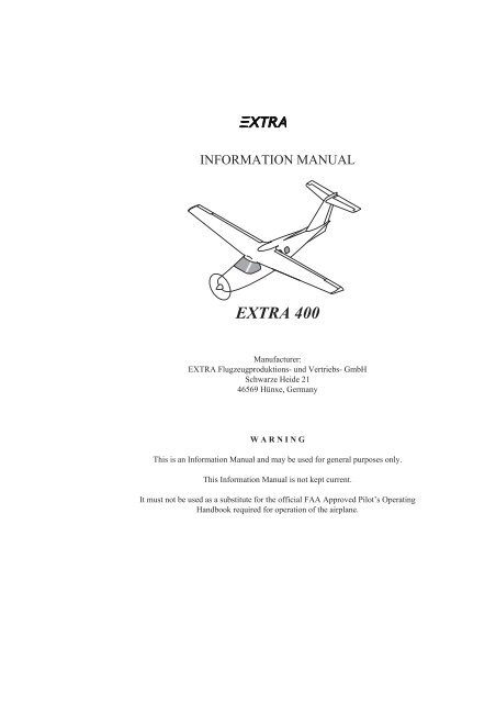
INFORMATION MANUAL<br />
EXTRA <strong>400</strong><br />
Manufacturer:<br />
EXTRA Flugzeugproduktions- und Vertriebs- GmbH<br />
Schwarze Heide 21<br />
46569 Hünxe, Germany<br />
WARNING<br />
This is an Information Manual and may be used for general purposes only.<br />
This Information Manual is not kept current.<br />
It must not be used as a substitute for the official FAA Approved Pilot’s Operating<br />
Handbook required for operation of the airplane.
Pilot’s Operating Handbook<br />
<strong>EA</strong> <strong>400</strong><br />
Coverage<br />
The Pilot’s Operating Handbook in the airplane at the time of delivery<br />
from EXTRA Flugzeugproduktions- und Vertriebs-GmbH<br />
contains information applicable to the <strong>EA</strong> <strong>400</strong> airplane designated<br />
by the serial number and registration number shown on the<br />
title page of this handbook. This information is based on data<br />
available at the time of publication.<br />
Revisions<br />
Changes and/or additions to this handbook will be covered by revisions<br />
published by EXTRA Flugzeugproduktions- und<br />
Vertriebs-GmbH. These revisions are distributed to <strong>EA</strong> <strong>400</strong> aircraft<br />
owners registered by EXTRA Flugzeugproduktions- und<br />
Vertriebs-GmbH at the time of revision issuance.<br />
Note<br />
It is the responsibility of the owner to maintain this handbook<br />
in a current status when it is being used for operational purposes.<br />
This handbook is valid only in a current status.<br />
Owners should contact their EXTRA dealer when ever the revision<br />
status of their handbook is in question, for example in case of<br />
the owner has changed.<br />
A revision bar will extend the full length of new or revised text<br />
and/or illustrations added on new or presently existing pages.<br />
This bar will be located adjacent to the applicable revised area on<br />
the inner margin of the page. All revised pages will carry the revision<br />
date.<br />
The following log of effective pages provides the dates of issue<br />
for original and revised pages and a listing of all pages in the<br />
handbook.<br />
Issued: 15. 11. October May 2005 1999<br />
i
Pilot’s Operating Handbook<br />
<strong>EA</strong> <strong>400</strong><br />
Notes<br />
Notes and safety notes in this handbook are marked by a boxed<br />
textmarker in the margin column and are written in semi-bold<br />
characters.<br />
Note<br />
Represents a remarkable hint.<br />
Important<br />
Represents an important hint.<br />
Caution<br />
Warning<br />
Represents a danger to equipment. The non-observation of this<br />
safety note will result in destruction of equipment. This safety<br />
note does not exclude a possible danger for persons.<br />
Represents a dangerous situation. The non-observation of this<br />
safety note may result in death or injuries.<br />
ii<br />
Issued: 15. October 1999
Pilot’s Operating Handbook<br />
<strong>EA</strong> <strong>400</strong><br />
Log of Revisions<br />
Dates of issue for original and revised pages are:<br />
Original . . . . . . . . . . . . . . . . . . . . . 1. April 1997<br />
Revision No. 1 . . . . . . . . . . . . . . 1. August 1997<br />
Revision No. 2 . . . . . . . . . . . . . . . 1. March 1998<br />
Edition No 2 . . . . . . . . . . . . . . 15. October 1999<br />
Revision No. 1, 2. Edition . . . 5. November 1999<br />
Revision No. 2, 2. Edition . . . . 28. January 2000<br />
Revision No. 3, 2. Edition. . . . . . . . 3. May 2000<br />
Revision No. 4, 2. Edition. . . . . 11. August 2000<br />
Revision No. 5, 2. Edition . . . 8. December 2000<br />
Revision No. 6, 2. Edition . . . 28. February 2001<br />
Revision No. 7, 2. Edition . . . . . . 26. April 2001<br />
Revision No. 8, 2. Edition . . . . . . . 13. July 2001<br />
Revision No. 9, 2. Edition . . 13. September 2001<br />
Revision No. 10, 2. Edition . . . 11. January 2002<br />
Revision No. 11, 2. Edition . . . . . . 15. July 2002<br />
Revision No. 12, 2. Edition. . . . . . 11. May 2005<br />
Date and sign of approval:<br />
LBA approved. . . . . . . . . . . . . . . 17. April 1997<br />
LBA approved . . . . . . . . . . . 5. November 1997<br />
LBA approved . . . . . . . . . . . . . . 11. March 1998<br />
LBA approved . . . . . . . . . . . . 1. December 1999<br />
LBA approved . . . . . . . . . . . 21. December 1999<br />
LBA approved . . . . . . . . . . . . . 4. February 2000<br />
LBA approved. . . . . . . . . . . . . . . . 12. May 2000<br />
LBA approved . . . . . . . . . . . 22. September 2000<br />
LBA approved . . . . . . . . . . . . . 2. February 2001<br />
LBA approved . . . . . . . . . . . . . . 12. March 2001<br />
LBA approved. . . . . . . . . . . . . . . . 28. June 2001<br />
LBA approved . . . . . . . . . . . . . . 1. October 2001<br />
LBA approved . . . . . . . . . . . . . . 1. October 2001<br />
LBA approved . . . . . . . . . . . . 13. February 2002<br />
LBA approved . . . . . . . . . . . 27. September 2002<br />
LBA accepted: . . . . . . . . . . . . . . . . 22. July 2005<br />
Approval N° <strong>EA</strong>SA.A.A.01005<br />
Issued: 15. 11. October May 2005 1999<br />
iii
Pilot’s Operating Handbook<br />
<strong>EA</strong> <strong>400</strong><br />
Page Date Page Date<br />
Title . . . . . . . . . . . . . . . . . . . . . . . . 11. May 2005<br />
i . . . . . . . . . . . . . . . . . . . . . . . . . . . 11. May 2005<br />
ii. . . . . . . . . . . . . . . . . . . . . . . . 15. October 1999<br />
iii thru iv . . . . . . . . . . . . . . . . . . . . 11. May 2005<br />
v thru vi . . . . . . . . . . . . . . . . . . 11. January 2002<br />
1-1 thru 1-2 . . . . . . . . . . . . . . . 15. October 1999<br />
1-3 . . . . . . . . . . . . . . . . . . . . . . . . . 11. May 2005<br />
1-4 thru 1-12 . . . . . . . . . . . . . . 15. October 1999<br />
2-1 . . . . . . . . . . . . . . . . . . . . . . . . . 15. July 2002<br />
2-2 . . . . . . . . . . . . . . . . . . . . . 5. November 1999<br />
2-3 thru 2-4 . . . . . . . . . . . . . . 28. February 2001<br />
2-5 thru 2-6 . . . . . . . . . . . . . . . 15. October 1999<br />
2-7 thru 2-8 . . . . . . . . . . . . . . 8. December 2000<br />
2-9 thru 2-12 . . . . . . . . . . . . . . . . . 15. July 2002<br />
2-13 . . . . . . . . . . . . . . . . . . . . . . . . 11. May 2005<br />
2-14 thru 2-24 . . . . . . . . . . . . . . . . 15. July 2002<br />
3-1 thru 3-2 . . . . . . . . . . . . . . 8. December 2000<br />
3-3 thru 3-4 . . . . . . . . . . . . . . . . . . . 3. May 2000<br />
3-5 thru 3-20 . . . . . . . . . . . . . 5. November 1999<br />
3-21 thru 3-24 . . . . . . . . . . . . 28. February 2001<br />
3-25 thru 3-50 . . . . . . . . . . . . 8. December 2000<br />
3-51 thru 3-52 . . . . . . . . . . . . 28. February 2001<br />
3-53 thru 3-56 . . . . . . . . . . . . 8. December 2000<br />
4-1 thru 4-2 . . . . . . . . . . . . . . . . . . . 3. May 2000<br />
4-3 thru 4-6 . . . . . . . . . . . . . . . 15. October 1999<br />
4-7 thru 4-11 . . . . . . . . . . . . . 5. November 1999<br />
4-12 thru 4-13 . . . . . . . . . . . . . . . . 15. July 2002<br />
4-14 . . . . . . . . . . . . . . . . . . . . 28. February 2001<br />
4-15 thru 4-18 . . . . . . . . . . . . 5. November 1999<br />
4-19 thru 4-26 . . . . . . . . . . . . . . . . 15. July 2002<br />
5-1 thru 5-6 . . . . . . . . . . . . . . . . . . . 3. May 2000<br />
5-7 thru 5-12 . . . . . . . . . . . . . . 15. October 1999<br />
5-13 thru 5-34 . . . . . . . . . . . . . . . . . 3. May 2000<br />
6-1 thru 6-4 . . . . . . . . . . . . . . . . . . . 3. May 2000<br />
6-5 thru 6-8 . . . . . . . . . . . . . . 8. December 2000<br />
6-9 thru 6-10 . . . . . . . . . . . . . . . . . . 3. May 2000<br />
6-11 thru 6-16 . . . . . . . . . . . . 8. December 2000<br />
6-17 thru 6-20 . . . . . . . . . . . . . . . . . 3. May 2000<br />
6-21 . . . . . . . . . . . . . . . . . . . . . . . . 15. July 2002<br />
6-22 thru 6-23 . . . . . . . . . . . 13. September 2001<br />
6-24 . . . . . . . . . . . . . . . . . . . . . 11. January 2002<br />
6-25 . . . . . . . . . . . . . . . . . . . 13. September 2001<br />
6-26 thru 6-27 . . . . . . . . . . . . . . . . 15. July 2002<br />
6-28 . . . . . . . . . . . . . . . . . . . 13. September 2001<br />
6-29 . . . . . . . . . . . . . . . . . . . . . . . . 15. July 2002<br />
6-30 . . . . . . . . . . . . . . . . . . . . . 11. January 2002<br />
6-31thru 6-32. . . . . . . . . . . . . . . . . 11. May 2005<br />
7-1 thru 7-2 . . . . . . . . . . . . . . . . . . 15. July 2002<br />
7-3 thru 7-4 . . . . . . . . . . . . . . 5. November 1999<br />
Log of Effective Pages<br />
7-5 . . . . . . . . . . . . . . . . . . . . . . . 11. August 2000<br />
7-6 . . . . . . . . . . . . . . . . . . . . . . 11. January 2002<br />
7-7 thru 7-8 . . . . . . . . . . . . . . . . . . 13. July 2001<br />
7-9 . . . . . . . . . . . . . . . . . . . . . 5. November 1999<br />
7-10 . . . . . . . . . . . . . . . . . . . . . . . . 15. July 2002<br />
7-11 thru 7-12 . . . . . . . . . . . . 28. February 2001<br />
7-13 thru 7-14 . . . . . . . . . . . . . . . . . 3. May 2000<br />
7-15 thru 7-16 . . . . . . . . . . . . 5. November 1999<br />
7-17 thru 7-18 . . . . . . . . . . . . 28. February 2001<br />
7-19 thru 7-35 . . . . . . . . . . . . 8. December 2000<br />
7-36 . . . . . . . . . . . . . . . . . . . . . . . . 15. July 2002<br />
7-37 . . . . . . . . . . . . . . . . . . . . 8. December 2000<br />
7-38 . . . . . . . . . . . . . . . . . . . . . . . . 15. July 2002<br />
7-39 thru 7-49 . . . . . . . . . . . . . . . . 13. July 2001<br />
7-50 thru 7-52 . . . . . . . . . . . . . . . . 15. July 2002<br />
7-53 thru 7-54 . . . . . . . . . . . . . . . . 11. May 2005<br />
7-55 thru 7-56 . . . . . . . . . . . . . . . . 15. July 2002<br />
8-1 thru 8-3 . . . . . . . . . . . . . . . 15. October 1999<br />
8-4 . . . . . . . . . . . . . . . . . . . . . . . . . 11. May 2005<br />
8-5 thru 8-10 . . . . . . . . . . . . . . 15. October 1999<br />
9-1 . . . . . . . . . . . . . . . . . . . . . . . . . 15. July 2002<br />
9-2 . . . . . . . . . . . . . . . . . . . . . . . . . 11. May 2005<br />
9-3 thru 9-4 . . . . . . . . . . . . . . 5. November 1999<br />
901-1 thru 901-9 . . . . . . . . . . 5. November 1999<br />
901-10 . . . . . . . . . . . . . . . . . . . 11. January 2002<br />
901-11 thru 903-6 . . . . . . . . . 5. November 1999<br />
904-1 thru 904-2 . . . . . . . . . . . . 11. August 2000<br />
904-3 . . . . . . . . . . . . . . . . . . . . 11. January 2002<br />
904-4 thru 904-6 . . . . . . . . . . . . 11. August 2000<br />
904-7 . . . . . . . . . . . . . . . . . . . 8. December 2000<br />
904-8 . . . . . . . . . . . . . . . . . . . . 11. January 2002<br />
904-9 thru 904-16 . . . . . . . . . . . 11. August 2000<br />
905-1 thru 905-6 . . . . . . . . . . 5. November 1999<br />
906-1 . . . . . . . . . . . . . . . . . . . . 11. January 2002<br />
906-2 thru 906-4 . . . . . . . . . . 5. November 1999<br />
907-1 thru 907-4 . . . . . . . . . . 8. December 2000<br />
908-1 thru 914-4 . . . . . . . . . . 5. November 1999<br />
915-1 thru 919-2 . . . . . . . . . . . 28. January 2000<br />
919-3 . . . . . . . . . . . . . . . . . . . . 11. January 2002<br />
919-4 . . . . . . . . . . . . . . . . . . . . 28. January 2000<br />
920-1 . . . . . . . . . . . . . . . . . . . . . . . 11. May 2005<br />
920-2 thru 920-3 . . . . . . . . . . . . . . 13. July 2001<br />
920-4 thru 920-7 . . . . . . . . . . . . . . 11. May 2005<br />
920-8 . . . . . . . . . . . . . . . . . . . . . . . 13. July 2001<br />
921-1 thru 921-8 . . . . . . . . . 13. September 2001<br />
922-1 thru 922-8 . . . . . . . . . . . 11. January 2002<br />
923-1 thru 923-14 . . . . . . . . . . . . . 15. July 2002<br />
924-1 thru 924-10 . . . . . . . . . . . . . 11. May 2005<br />
925-1 thru 925-10 . . . . . . . . . . . . . 11. May 2005<br />
iv<br />
Issued: Issued: 15. 11. October May 2005 1999
Pilot’s Operating Handbook<br />
<strong>EA</strong> <strong>400</strong><br />
TABLE OF CONTENTS<br />
Section 1<br />
Section 2<br />
Section 3<br />
Section 4<br />
Section 5<br />
Section 6<br />
Section 7<br />
Section 8<br />
Section 9<br />
General<br />
Limitations<br />
Emergency Procedures<br />
Normal Procedures<br />
Performance<br />
Weight and Balance and Equipment List<br />
Description of the Airplane and its Systems<br />
Handling, Servicing and Maintenance<br />
Supplements<br />
Issued: 15. 11. October January 2002<br />
1999<br />
v
Pilot’s Operating Handbook<br />
<strong>EA</strong> <strong>400</strong><br />
Intentionally left blank<br />
vi<br />
Issued: 15. 11. October January 2002 1999
Pilot’s Operating Handbook<br />
<strong>EA</strong> <strong>400</strong><br />
Section 1<br />
General<br />
Table of Contents<br />
Paragraph<br />
Page<br />
1.1 Introduction . . . . . . . . . . . . . . . . . . . . . . . . . . . . . . . . . . . . . . . . . . . . . . . . . . . . . . . . . . . . . . . . . . . . . . . . . . . . . . . . . . . . . . . . . . . . .1-3<br />
1.2 Three-View Drawing . . . . . . . . . . . . . . . . . . . . . . . . . . . . . . . . . . . . . . . . . . . . . . . . . . . . . . . . . . . . . . . . . . . . . . . . . . .1-5<br />
1.3 Engine . . . . . . . . . . . . . . . . . . . . . . . . . . . . . . . . . . . . . . . . . . . . . . . . . . . . . . . . . . . . . . . . . . . . . . . . . . . . . . . . . . . . . . . . . . . . . . . . . . . . . . . . .1-5<br />
1.4 Propeller . . . . . . . . . . . . . . . . . . . . . . . . . . . . . . . . . . . . . . . . . . . . . . . . . . . . . . . . . . . . . . . . . . . . . . . . . . . . . . . . . . . . . . . . . . . . . . . . . . . .1-5<br />
1.5 Fuel . . . . . . . . . . . . . . . . . . . . . . . . . . . . . . . . . . . . . . . . . . . . . . . . . . . . . . . . . . . . . . . . . . . . . . . . . . . . . . . . . . . . . . . . . . . . . . . . . . . . . . . . . . . . . . .1-5<br />
1.6 Oil. . . . . . . . . . . . . . . . . . . . . . . . . . . . . . . . . . . . . . . . . . . . . . . . . . . . . . . . . . . . . . . . . . . . . . . . . . . . . . . . . . . . . . . . . . . . . . . . . . . . . . . . . . . . . . . . . .1-5<br />
1.7 Coolant . . . . . . . . . . . . . . . . . . . . . . . . . . . . . . . . . . . . . . . . . . . . . . . . . . . . . . . . . . . . . . . . . . . . . . . . . . . . . . . . . . . . . . . . . . . . . . . . . . . . . . .1-6<br />
1.8 Maximum Certificated Weights. . . . . . . . . . . . . . . . . . . . . . . . . . . . . . . . . . . . . . . . . . . . . . . . . . . . .1-6<br />
1.9 Typical Airplane Weights . . . . . . . . . . . . . . . . . . . . . . . . . . . . . . . . . . . . . . . . . . . . . . . . . . . . . . . . . . . . . . . . .1-6<br />
1.10 Cabin and Entry Dimensions . . . . . . . . . . . . . . . . . . . . . . . . . . . . . . . . . . . . . . . . . . . . . . . . . . . . . . . . . .1-6<br />
1.11 Specific Loadings. . . . . . . . . . . . . . . . . . . . . . . . . . . . . . . . . . . . . . . . . . . . . . . . . . . . . . . . . . . . . . . . . . . . . . . . . . . . . . . . . . .1-6<br />
1.12 Symbols, Abbreviations and Terminology . . . . . . . . . . . . . . . . . . . . . . . . . . . . . . .1-7<br />
1.12a General Airspeed Terminology and Symbols. . . . . . . . . . . . . . . . . . . . . . . . . . . . . . .1-7<br />
1.12b Meteorological Terminology . . . . . . . . . . . . . . . . . . . . . . . . . . . . . . . . . . . . . . . . . . . . . . . . . . . . . . . . . . . . . .1-8<br />
1.12c Power Terminology . . . . . . . . . . . . . . . . . . . . . . . . . . . . . . . . . . . . . . . . . . . . . . . . . . . . . . . . . . . . . . . . . . . . . . . . . . . . . . . .1-9<br />
1.12d Engine Controls and Instruments . . . . . . . . . . . . . . . . . . . . . . . . . . . . . . . . . . . . . . . . . . . . . . . . . . . . . .1-9<br />
1.12e Airplane Performance and Flight Planning Terminology. . . . . .1-10<br />
1.12f Weight and Balance . . . . . . . . . . . . . . . . . . . . . . . . . . . . . . . . . . . . . . . . . . . . . . . . . . . . . . . . . . . . . . . . . . . . . . . . . . . . .1-10<br />
1.13 Conversion to U.S. Units . . . . . . . . . . . . . . . . . . . . . . . . . . . . . . . . . . . . . . . . . . . . . . . . . . . . . . . . . . . . . . . . .1-11<br />
Issued: 15. October 1999<br />
1-1
Section 1<br />
Pilot’s Operating Handbook<br />
<strong>EA</strong> <strong>400</strong><br />
Intentionally left blank<br />
1-2<br />
Issued: 15. October 1999
Pilot’s Operating Handbook<br />
<strong>EA</strong> <strong>400</strong><br />
Section 1<br />
General<br />
1 General<br />
1.1 Introduction<br />
This handbook includes the material required to be furnished<br />
to the pilot by the Federal Aviation Regulations and additional<br />
information provided by the EXTRA<br />
Flugzeugproduktions- und Vertriebs-GmbH and constitutes<br />
the LBA accepted and <strong>EA</strong>SA Approved Airplane Flight<br />
Manual.<br />
This manual also constitutes the FAA Approved Airplane<br />
Flight Manual for US operations.<br />
The material spreads over 9 sections. Specific information can be<br />
rapidly found by referring to the contents page for the appropriate<br />
section, then referring to the table of contents on the first page of<br />
the respective section.<br />
1 Noise Level<br />
The noise level with standard tail pipe has been established in accordance<br />
a with FAR 36 Appendix G, as 79.0 dB(A),<br />
b with ICAO Annex 16, as 82.6 dB(A).<br />
No determination has been made by the LBA or the FAA that the<br />
noise levels of this airplane are or should be acceptable or unacceptable<br />
for operation at, into, or out of, any airport.<br />
Issued: 15. Issued: October 11. 1999 May 2005<br />
1-3
Section 1<br />
General<br />
Pilot’s Operating Handbook<br />
<strong>EA</strong> <strong>400</strong><br />
1.2 Three-View Drawing<br />
3.09 m<br />
(10.14 ft)<br />
2.595 m (8.51 ft)<br />
9.57 m (31.4 ft)<br />
11.50 m (37.73 ft)<br />
2.20 m (7.22 ft)<br />
Maximum Propeller Diameter:<br />
1.95 m (76.77 in.)<br />
Propeller Ground Clearance:<br />
260 mm (10.24 in.)<br />
1.46 m<br />
(4.79 ft)<br />
3.80 m<br />
(12.47 ft)<br />
Figure 1-1<br />
1-4<br />
Issued: 15. October 1999
Pilot’s Operating Handbook<br />
<strong>EA</strong> <strong>400</strong><br />
Section 1<br />
General<br />
1.3 Engine<br />
1 Number of Engines: 1<br />
2 Engine Manufacturer: Teledyne Continental Motors<br />
3 Engine Model Number: TSIOL-550-C<br />
4 Engine Type:<br />
Six-cylinder, horizontally opposed, liquid cooled, turbocharged,<br />
intercooled, fuel-injected, direct drive engine, 9014 ccm (550 cubic<br />
inch) displacement.<br />
a Takeoff Power 261 KW (350 BHP) at 2,600 RPM*<br />
b<br />
Maximum Continuous Power:<br />
242 KW (325 BHP) at 2,500 RPM**<br />
*) and 39.5 inches Hg. manifold pressure<br />
**) and 37.5 inches Hg. manifold pressure<br />
1.4 Propeller<br />
1 Number of Propellers: 1<br />
2 Propeller Manufacturer: MT-Propeller<br />
3 Propeller Model Number: MTV-14-D/195-30a<br />
4 Number of Blades: 4<br />
5 Propeller Diameter: 1.95 m (76.77 in.)<br />
6 Propeller Type:<br />
constant speed, hydraulic actuated, pitch range: 26°<br />
1.5 Fuel<br />
1 Fuel Grade:<br />
100 or 100LL (Minimum Grade Aviation Gasoline conforming<br />
to ASTM D910-76 & MIL-G-5572, latest revision)<br />
1 Total Capacity: 468 l (124 U.S. Gallons)<br />
2 Total Usable Fuel: 404 l (107 U.S. Gallons)<br />
3 Unusable Fuel: 64 l (17 U.S. Gallons)<br />
1.6 Oil<br />
1 Oil Grade (SAE):<br />
a All temperatures: SAE 20W-50<br />
b above 4°C (40°F) ambient air (S.L.): SAE 50<br />
Issued: 15. October 1999<br />
1-5
Section 1<br />
General<br />
Pilot’s Operating Handbook<br />
<strong>EA</strong> <strong>400</strong><br />
c below 4°C (40°F) ambient air (S.L.): SAE 30<br />
2 Total Oil Capacity: 12.3 l (13 Quarts)<br />
3 Drain and Refill Quantity: 11.4 l (12 Quarts)<br />
4 Oil Quantity Operating Range 7.6 to 11.4 l (8 to 12 Quarts)<br />
1.7 Coolant<br />
The fluid used for cooling the engine is to be a 60/40 mixture of<br />
coolant/water. Coolant (ethylene glycol) approved for use is:<br />
Texaco ETX 6024 TCM P/N 653125<br />
1.8 Maximum Certificated Weights<br />
1 Maximum Ramp Weight: 1999 kg (4407 lbs.)<br />
2 Maximum Takeoff Weight: 1999 kg (4407 lbs.)<br />
3 Maximum Landing Weight: 1999 kg (4407 lbs.)<br />
1.9 Typical Airplane Weights<br />
1 Standard Empty Weight: 1430 kg (3153 lbs.)<br />
1.10 Cabin and Entry Dimensions<br />
1 Cabin Width (Maximum): 1.39 m (4.56 ft.)<br />
2 Cabin Length (Front to rear bulkhead): 4.13 m (13.55 ft.)<br />
3 Cabin Height (Maximum) 1.24 m (4.07 ft.)<br />
4 Entry Door Width: 0.68 m (2.23 ft.)<br />
5 Entry Door Height: 1.15 m (3.77 ft.)<br />
6 Emergency Exit Window Width: 0.68 m (2.23 ft.)<br />
7 Emergency Exit Window Height: 0.50 m (1.64 ft.)<br />
1.11 Specific Loadings<br />
1 Wing Loading: 140.1 kg/m 2 (28.7 lbs/sq.ft.)<br />
2 Power Loading: 5.7 kg/BHP (12.6 lbs/BHP)<br />
1-6<br />
Issued: 15. October 1999
Pilot’s Operating Handbook<br />
<strong>EA</strong> <strong>400</strong><br />
Section 1<br />
General<br />
1.12 Symbols, Abbreviations and Terminology<br />
1.12a General Airspeed Terminology and Symbols<br />
CAS<br />
KCAS<br />
GS<br />
IAS<br />
KIAS<br />
TAS<br />
V O<br />
V FE<br />
V LE<br />
V LO<br />
V NE<br />
V NO<br />
Calibrated Airspeed means the indicated speed of an aircraft, corrected<br />
for position and instrument error. Calibrated airspeed is<br />
equal to true airspeed in standard atmosphere at sea level.<br />
Calibrated Airspeed expressed in “knots”.<br />
Ground Speed is the speed of an airplane relative to the ground.<br />
Indicated Airspeed is the speed of an aircraft as shown in the airspeed<br />
indicator when corrected for instrument error. IAS values<br />
published in this handbook assume zero instrument error.<br />
Indicated Airspeed expressed in “knots”.<br />
True Airspeed is the airspeed of an airplane relative to undisturbed<br />
air which is the CAS corrected for altitude, temperature and<br />
compressibility.<br />
Operating maneuvering Speed is the maximum speed at which<br />
application of full available aerodynamic control will not overstress<br />
the airplane.<br />
Maximum Flap extended speed is the highest speed permissible<br />
with wing flaps in a prescribed extended position.<br />
Maximum Landing Gear Extended Speed is the maximum speed<br />
at which an aircraft can be safely flown with the landing gear extended.<br />
Maximum Landing Gear Operating Speed is the maximum speed<br />
at which the landing gear can be safely extended or retracted.<br />
Never Exceed Speed is the speed limit that may not be exceeded<br />
at any time.<br />
Maximum Structural Cruising Speed is the speed that should not<br />
be exceeded except in smooth air and then only with caution.<br />
Issued: 15. October 1999<br />
1-7
Section 1<br />
General<br />
V S<br />
V SO<br />
V X<br />
V Y<br />
Pilot’s Operating Handbook<br />
<strong>EA</strong> <strong>400</strong><br />
Stalling Speed or the minimum steady flight speed at which the<br />
airplane is controllable.<br />
Stalling Speed or the minimum steady flight speed at which the<br />
airplane is controllable in the landing configuration.<br />
Best Angle-of-Climb Speed is the airspeed which delivers the<br />
greatest gain of altitude in the shortest possible horizontal distance.<br />
Best Rate-of-Climb Speed is the airspeed which delivers the<br />
greatest gain in altitude in the shortest possible time.<br />
1.12b Meteorological Terminology<br />
ISA<br />
OAT<br />
Indicated<br />
Pressure<br />
Altitude<br />
Pressure<br />
Altitude<br />
Station<br />
Pressure<br />
International Standard Atmosphere in which<br />
a The air is a dry perfect gas;<br />
b The temperature at sea level is 15° Celsius (59°<br />
Fahrenheit);<br />
c The pressure at sea level is 1013.2 mb (29.92 inches hg.);<br />
d The temperature gradient from sea level to the altitude at<br />
which the temperature is —56.5°C (—69.7°F) is —1.98°C<br />
(—3.564°F) per 1,000 foot and zero above that altitude.<br />
Outside Air Temperature is the free air static temperature, obtained<br />
either from inflight temperature indications or ground meteorological<br />
sources, adjusted for instrument error and<br />
compressibility effects.<br />
The number actually read from an altimeter when the barometric<br />
subscale has been set to 1013.2 mb (29.92 in. hg. ).<br />
Altitude measured from standard sea level pressure (1013.2 mb/<br />
29.92 in. hg.) by a pressure or barometric altimeter. It is the indicated<br />
pressure altitude corrected for position and instrument error.<br />
In this Handbook, altimeter instrument errors are assumed to<br />
be zero.<br />
Actual atmospheric pressure at field elevation.<br />
1-8<br />
Issued: 15. October 1999
Pilot’s Operating Handbook<br />
<strong>EA</strong> <strong>400</strong><br />
Section 1<br />
General<br />
Wind<br />
The wind velocities recorded as variables on the charts of this<br />
Handbook are to be understood as the headwind or tailwind components<br />
of the reported winds.<br />
1.12c Power Terminology<br />
Takeoff Power<br />
Maximum<br />
Continuous<br />
Power (MCP)<br />
Idle Power<br />
The maximum power permissible for takeoff (may be time limited).<br />
The maximum power for unrestricted periods of use.<br />
The power required to run an engine at the lowest speed that will<br />
ensure satisfactory engine operation.<br />
1.12d Engine Controls and Instruments<br />
Throttle or<br />
Power Control<br />
Lever<br />
Propeller<br />
Control<br />
Mixture<br />
Control<br />
EGT Gauge<br />
TIT Gauge<br />
Tachometer<br />
The lever used to control engine power, from the lowest through<br />
the highest power, by controlling the air and the fuel flow. The extreme<br />
lever positions are called OPEN (forward position) and<br />
CLOSE (aft position).<br />
The lever used to select the propeller blade angle of attack. It provides<br />
a mechanical linkage to the propeller governor. In the<br />
FULL AFT position of the lever the angle of attack is high, in the<br />
FULL FORWARD position it is low.<br />
The mixture control provides a mechanical linkage with the mixture<br />
control valve of the fuel control unit, to adjust the air/fuel<br />
mixture. It is also a primary means to shut down the engine. The<br />
most forward position of the mixture control lever is called<br />
RICH, the aft position is called IDLE/CUT-OFF.<br />
The exhaust gas temperature indicator is the instrument used to<br />
identify the lean fuel flow mixtures for various power settings.<br />
A temperature measuring system that senses exhaust gas temperature<br />
at the turbine inlet.<br />
An instrument that indicates rotational speed. The speed is shown<br />
as propeller revolutions per minute (RPM).<br />
Issued: 15. October 1999<br />
1-9
Section 1<br />
General<br />
Propeller<br />
Governor<br />
Pilot’s Operating Handbook<br />
<strong>EA</strong> <strong>400</strong><br />
The device that regulates the rpm of the engine/propeller by increasing<br />
or decreasing the propeller pitch, through a pitch change<br />
mechanism in the propeller hub.<br />
1.12e Airplane Performance and Flight Planning Terminology<br />
Climb<br />
Gradient<br />
Demonstrated<br />
Crosswind<br />
Velocity<br />
The demonstrated ratio of the change in height during a portion of<br />
a climb, to the horizontal distance traversed in the same time interval.<br />
The demonstrated crosswind velocity is the velocity of the crosswind<br />
component for which adequate control of the airplane during<br />
takeoff and landing was actually demonstrated during<br />
certification tests.<br />
1.12f Weight and Balance<br />
Reference<br />
Datum<br />
Station<br />
Arm<br />
Moment<br />
Center of<br />
Gravity (C.G.)<br />
C.G. Arm<br />
C.G. Limits<br />
Usable Fuel<br />
An imaginary vertical plane from which all horizontal distances<br />
are measured for balance purposes.<br />
A location along the airplane fuselage usually given in terms of<br />
distance from the reference datum.<br />
The horizontal distance from the reference datum to the center of<br />
gravity (C.G.) of an item.<br />
The product of the weight of an item multiplied by its arm.<br />
The point at which an airplane would balance if suspended. Its<br />
distance from the reference datum is found by dividing the total<br />
moment by the total weight of the airplane.<br />
The arm obtained by adding the airplane’s individual moments<br />
and dividing the sum by the total weight.<br />
The extreme center of gravity locations within which the airplane<br />
must be operated at a given weight.<br />
Fuel available for flight planning.<br />
1-10<br />
Issued: 15. October 1999
Pilot’s Operating Handbook<br />
<strong>EA</strong> <strong>400</strong><br />
Section 1<br />
General<br />
Unusable Fuel<br />
Standard<br />
Empty Weight<br />
Basic Empty<br />
Weight<br />
Payload<br />
Useful Load<br />
Zero Fuel<br />
Weight<br />
Maximum<br />
Ramp Weight<br />
Maximum<br />
Takeoff<br />
Weight<br />
Maximum<br />
Landing<br />
Weight<br />
Minimum<br />
Weight<br />
Maximum<br />
Empty Weight<br />
Fuel remaining after a runout test has been completed in accordance<br />
with certification basis.<br />
Weight of a standard airplane including unusable fuel, full operating<br />
fluids and full oil.<br />
Standard empty weight plus optional equipment.<br />
Weight of occupants, cargo and baggage.<br />
Difference between takeoff weight, or ramp weight if applicable,<br />
and basic empty weight.<br />
Basic empty weight plus payload but no usable fuel.<br />
Maximum weight approved for ground maneuver. (It includes<br />
weight of start, taxi and run up fuel.)<br />
Maximum weight approved for the start of the takeoff run.<br />
Maximum weight approved for the landing touchdown.<br />
Standard empty weight plus minimum crew (1 pilot) and fuel for<br />
half an hour operating the airplane at maximum continuos power.<br />
Maximum approved empty weight of airplane including unusable<br />
fuel, full operating fluids and full oil.<br />
1.13 Conversion to U.S. Units<br />
Multiply kg by 2.2 to obtain lbs.<br />
Multiply m by 39.37 to obtain in.<br />
Multiply kgm by 0.866 to obtain in.lbs./100<br />
Issued: 15. October 1999<br />
1-11
Section 1<br />
General<br />
Pilot’s Operating Handbook<br />
<strong>EA</strong> <strong>400</strong><br />
Intentionally left blank<br />
1-12<br />
Issued: 15. October 1999
Pilot’s Operating Handbook<br />
<strong>EA</strong> <strong>400</strong><br />
Section 2<br />
Limitations<br />
Table of Contents<br />
Paragraph<br />
Page<br />
2.1 Introduction . . . . . . . . . . . . . . . . . . . . . . . . . . . . . . . . . . . . . . . . . . . . . . . . . . . . . . . . . . . . . . . . . . . . . . . . . . . . . . . . . . . . . . . . . . . . .2-3<br />
2.2 Airspeed Limitations . . . . . . . . . . . . . . . . . . . . . . . . . . . . . . . . . . . . . . . . . . . . . . . . . . . . . . . . . . . . . . . . . . . . . . . . . . .2-4<br />
2.3 Airspeed Indicator Markings . . . . . . . . . . . . . . . . . . . . . . . . . . . . . . . . . . . . . . . . . . . . . . . . . . . . . . . . . .2-5<br />
2.4 Leaning Limitations . . . . . . . . . . . . . . . . . . . . . . . . . . . . . . . . . . . . . . . . . . . . . . . . . . . . . . . . . . . . . . . . . . . . . . . . . . . . .2-5<br />
2.5 Power Plant Limitations . . . . . . . . . . . . . . . . . . . . . . . . . . . . . . . . . . . . . . . . . . . . . . . . . . . . . . . . . . . . . . . . . . . .2-5<br />
2.6 Powerplant Instrument Markings . . . . . . . . . . . . . . . . . . . . . . . . . . . . . . . . . . . . . . . . . . . . . . . .2-7<br />
2.7 Miscellaneous Instrument Markings . . . . . . . . . . . . . . . . . . . . . . . . . . . . . . . . . . . . . . . . . . .2-8<br />
2.8 Weight Limits. . . . . . . . . . . . . . . . . . . . . . . . . . . . . . . . . . . . . . . . . . . . . . . . . . . . . . . . . . . . . . . . . . . . . . . . . . . . . . . . . . . . . . . . . .2-8<br />
2.9 Center of Gravity Limits . . . . . . . . . . . . . . . . . . . . . . . . . . . . . . . . . . . . . . . . . . . . . . . . . . . . . . . . . . . . . . . . . . .2-8<br />
2.10 Maneuver Limits . . . . . . . . . . . . . . . . . . . . . . . . . . . . . . . . . . . . . . . . . . . . . . . . . . . . . . . . . . . . . . . . . . . . . . . . . . . . . . . . . . .2-8<br />
2.11 Flight Load Factor Limits. . . . . . . . . . . . . . . . . . . . . . . . . . . . . . . . . . . . . . . . . . . . . . . . . . . . . . . . . . . . . . . . .2-9<br />
2.12 Flight Crew Limits. . . . . . . . . . . . . . . . . . . . . . . . . . . . . . . . . . . . . . . . . . . . . . . . . . . . . . . . . . . . . . . . . . . . . . . . . . . . . . . .2-9<br />
2.13 Kinds of Operation . . . . . . . . . . . . . . . . . . . . . . . . . . . . . . . . . . . . . . . . . . . . . . . . . . . . . . . . . . . . . . . . . . . . . . . . . . . . . . .2-9<br />
2.14 Kinds of Operation Equipment List . . . . . . . . . . . . . . . . . . . . . . . . . . . . . . . . . . . . . . . . . .2-10<br />
2.15 Fuel Limitations . . . . . . . . . . . . . . . . . . . . . . . . . . . . . . . . . . . . . . . . . . . . . . . . . . . . . . . . . . . . . . . . . . . . . . . . . . . . . . . . . .2-16<br />
2.16 Maximum Operating Altitude Limit. . . . . . . . . . . . . . . . . . . . . . . . . . . . . . . . . . . . . . . . .2-16<br />
2.17 Cabin Pressurization Limits. . . . . . . . . . . . . . . . . . . . . . . . . . . . . . . . . . . . . . . . . . . . . . . . . . . . . . . . . .2-16<br />
2.18 Maximum Passenger Seating Limits . . . . . . . . . . . . . . . . . . . . . . . . . . . . . . . . . . . . . . . . .2-16<br />
2.19 Limitations for Electrothermal Anti-ice Devices . . . . . . . . . . . . . . . .2-16<br />
2.20 Structural Temperature/Color Limitation . . . . . . . . . . . . . . . . . . . . . . . . . . . .2-17<br />
2.21 Flap Limitations . . . . . . . . . . . . . . . . . . . . . . . . . . . . . . . . . . . . . . . . . . . . . . . . . . . . . . . . . . . . . . . . . . . . . . . . . . . . . . . . . .2-17<br />
2.22 Crosswind Component . . . . . . . . . . . . . . . . . . . . . . . . . . . . . . . . . . . . . . . . . . . . . . . . . . . . . . . . . . . . . . . . . . . . .2-17<br />
2.23 Placards . . . . . . . . . . . . . . . . . . . . . . . . . . . . . . . . . . . . . . . . . . . . . . . . . . . . . . . . . . . . . . . . . . . . . . . . . . . . . . . . . . . . . . . . . . . . . . . . . . .2-17<br />
Issued: 15. October July 20021999<br />
2-1
Section 2<br />
Pilot’s Operating Handbook<br />
<strong>EA</strong> <strong>400</strong><br />
Intentionally left blank<br />
2-2<br />
Issued: 5. 15. November October 1999
Pilot’s Operating Handbook<br />
<strong>EA</strong> <strong>400</strong><br />
Section 2<br />
Limitations<br />
2 Limitations<br />
2.1 Introduction<br />
This section presents the various operating limitations, instrument<br />
markings, color coding and basic placards necessary for the<br />
safe operation of the <strong>EA</strong> <strong>400</strong>, its power plant, systems and standard<br />
equipment.<br />
Note<br />
In case an aircraft is equipped with specific options, the necessary<br />
additional information for safe operation like limitations,<br />
procedures, performance data, and other is shown in<br />
section 9.<br />
The limitations included in this section and in section 9 are approved<br />
by the Luftfahrt Bundesamt (LBA). Observance of these operating<br />
limitations is required by national aviation regulations.<br />
Issued: 15. 28. October February1999<br />
2001<br />
2-3
Section 2<br />
Limitations<br />
Pilot’s Operating Handbook<br />
<strong>EA</strong> <strong>400</strong><br />
2.2 Airspeed Limitations<br />
Speed KCAS KIAS Remarks<br />
Maneuvering Speed V O<br />
1450 kg (3197 lbs.)<br />
1999 kg (4407 lbs.)<br />
Maximum Flap Extended<br />
Speed V FE 15°<br />
30°<br />
134<br />
158<br />
120<br />
111<br />
133<br />
156<br />
120<br />
109<br />
Maximum Landing Gear<br />
Operation SpeedV LO 142 140<br />
Maximum Landing Gear<br />
Extended Speed V LE 142 140<br />
Never Exceed Speed V NE 221 219<br />
Maximum Structural<br />
Cruising Speed V NO 190 188<br />
Do not make full or abrupt<br />
control movements above this<br />
speed. For weights between the<br />
given ones the values are<br />
assumed to be linear.<br />
Do not exceed this speed with the<br />
given flap setting.<br />
Do not operate landing gear<br />
above this speed.<br />
Do not exceed this speed with<br />
landing gear extended.<br />
Do not exceed this speed in any<br />
operation.<br />
Do not exceed this speed except<br />
in smooth air and then only with<br />
caution.<br />
2-4 Issued: 28. 15. February October 2001 1999
Pilot’s Operating Handbook<br />
<strong>EA</strong> <strong>400</strong><br />
Section 2<br />
Limitations<br />
2.3 Airspeed Indicator Markings<br />
Marking<br />
KIAS Value or<br />
Range<br />
Significance<br />
White Arc 58 thru 109<br />
Full Flap Operating Range. Lower limit is<br />
maximum weight stalling speed in landing<br />
configuration. Upper limit is maximum<br />
speed permissible with flaps (30°) extended<br />
Green Arc 76 thru 188<br />
Normal Operating Range. Lower limit is<br />
maximum weight stalling speed with flaps<br />
and landing gear retracted. Upper limit is<br />
maximum structural cruising speed.<br />
Yellow Arc 188 thru 219<br />
Operations must be conducted with caution<br />
and only in smooth air.<br />
Red Line 219 Maximum speed for all operations.<br />
2.4 Leaning Limitations<br />
Mixture full RICH at all engine powers above 75% cruise power<br />
2.5 Power Plant Limitations<br />
1 Number of Engines: 1<br />
2 Engine Manufacturer: Teledyne Continental Motors<br />
3 Engine Model Number: TSIOL-550-C<br />
4 Engine Operating Limits:<br />
a Takeoff Power (Max., limited to 5min):261 KW (350 BHP)<br />
b Maximum Continuous Power: 242 KW (325 BHP)<br />
5 Manifold Pressure (Max. Takeoff Power): 39.5 in.Hg. (1.34 bar)<br />
6 Manifold Pressure (MCP): 37.5 in.Hg. (1.27 bar) up to 20,000 ft<br />
reduce 1.1 in.Hg. per 1000 ft to 32 in.Hg. (1.08 bar) at 25,000 ft<br />
7 Exhaust Gas Temperature (Maximum) 954 °C (1750 °F)<br />
8 Cylinder Head Temperature (Maximum) 191°C (375°F)<br />
9 Oil Temperature:<br />
a Minimum takeoff: 38°C (100°F)<br />
b Maximum: 110°C (230°F)<br />
10 Oil Pressure:<br />
a Minimum, Idle: 0.7 bar (10 PSI)<br />
b Maximum Allowable (cold oil): 7 bar (100 PSI)<br />
Issued: 15. October 1999<br />
2-5
Section 2<br />
Limitations<br />
Pilot’s Operating Handbook<br />
<strong>EA</strong> <strong>400</strong><br />
11 Coolant Temperature<br />
a Minimum takeoff: 66°C (150°F)<br />
b Maximum: 110°C (230°F)<br />
12 Fuel Pressure<br />
a Minimum: -0.14 bar (-2 PSI)<br />
b Maximum: 1.14 bar (16.5 PSI)<br />
13 Turbine Inlet Temperature (Maximum): 954°C (1750°F)<br />
14 Fuel Grade:<br />
100 or 100LL (Minimum Grade Aviation Gasoline conforming<br />
to ASTM D910-76 & MIL-G-5572, latest revision)<br />
15 Oil Grade (SAE):<br />
a All temperatures: SAE 20W-50<br />
b Above 4°C (40°F) ambient air (S.L.): SAE 50<br />
c Below 4°C (40°F) ambient air (S.L.): SAE 30<br />
16 Coolant Grade:<br />
Coolant used in the engine is to be a 60/40 mixture of ethylene<br />
glycol/destilled water. Coolant approved for use is:<br />
Texaco ETX 6024, TCM P/N: 653125<br />
17 Number of Propellers: 1<br />
18 Propeller Manufacturer: MT-Propeller<br />
19 Propeller Hub Number: MTV-14-D<br />
20 Number of Blades: 4<br />
21 Blade Model Numbers: 195-30a<br />
22 Propeller Diameter: 1.95 m (76.77 in.)<br />
23 Propeller Blade Angle at radius 680 mm (26.77 in):<br />
12° ±0.2° thru 38° ±1°<br />
24 Rotational Speed Restrictions:<br />
a Maximum Takeoff Speed 2,600 RPM<br />
b Maximum Continuous Speed 2,500 RPM<br />
2-6<br />
Issued: 15. October 1999
Pilot’s Operating Handbook<br />
<strong>EA</strong> <strong>400</strong><br />
Section 2<br />
Limitations<br />
2.6 Powerplant Instrument Markings<br />
Instrument<br />
Red<br />
Line<br />
Min.<br />
Limit<br />
Yellow Arc Green Arc Yellow Arc<br />
Caution<br />
Range<br />
Normal<br />
Operating<br />
Caution or<br />
Takeoff<br />
Red<br />
Line<br />
Max.<br />
Limit<br />
Tachometer, RPM 600-2,500 2,500-2,600 2,600<br />
Manifold Pressure<br />
in. Hg.<br />
bar<br />
Exhaust Gas Temp.<br />
°C<br />
°F<br />
Cylinder Head Temp.<br />
°C<br />
°F<br />
Oil Temperature<br />
°C<br />
°F<br />
Oil Pressure<br />
bar<br />
PSI<br />
Coolant Temperature<br />
°C<br />
°F<br />
Fuel Pressure<br />
bar<br />
PSI<br />
Turbine Inlet Temp.<br />
°C<br />
°F<br />
38<br />
100<br />
0.7<br />
10<br />
66<br />
150<br />
0.7-2.1<br />
10-30<br />
0-0.21<br />
0-3<br />
0-37.5<br />
0-1.27<br />
650-954<br />
1200-1750<br />
93-191<br />
200-375<br />
77-93<br />
170-200<br />
2.1-4.1<br />
30-60<br />
82-93<br />
180-200<br />
0.21-0.41<br />
3-6<br />
37.5-39.5<br />
1.27-1.34<br />
93-110<br />
200-230<br />
4.1-7<br />
60-100<br />
93-110<br />
200-230<br />
>0.41<br />
>6<br />
39.5<br />
1.34<br />
954<br />
1750<br />
191<br />
375<br />
110<br />
230<br />
7<br />
100<br />
110<br />
230<br />
954<br />
1750<br />
Vacuum Diff. Press.<br />
in. Hg 4.5 4.5-5.2 5.2<br />
Issued: 15. 8. December October 1999 2000<br />
2-7
Section 2<br />
Limitations<br />
Pilot’s Operating Handbook<br />
<strong>EA</strong> <strong>400</strong><br />
2.7 Miscellaneous Instrument Markings<br />
Instrument<br />
Red<br />
Line<br />
Min.<br />
Limit<br />
Yellow Arc Green Arc Yellow Arc<br />
Caution<br />
Range<br />
Normal<br />
Operating<br />
Caution or<br />
Takeoff<br />
Red<br />
Line<br />
Max.<br />
Limit<br />
Voltmeter, V 23 23-26 26-29 29-32 32<br />
Cabin Altitude, ft 10,000<br />
Cabin Differential<br />
Pressure, PSI<br />
5.5<br />
Fuel Quantity<br />
“0" -indication at 32 l (8.5 U.S. Gallons) unusable fuel<br />
each tank,<br />
red arc from 7 l (1.85 U.S. Gallons) to<br />
32 l (8.5 U.S. Gallons) unusable<br />
2.8 Weight Limits<br />
1 Maximum Ramp Weight: 1999 kg (4407 lbs.)<br />
2 Maximum Takeoff Weight: 1999 kg (4407 lbs.)<br />
3 Maximum Landing Weight: 1999 kg (4407 lbs.)<br />
4 Maximum Zero Fuel Weight: 1959 kg (4319 lbs.)<br />
5 Maximum Empty Weight: 1555 kg (3428 lbs.)<br />
6 Maximum Weight in Baggage Compartment: 90 kg (198 lbs.)<br />
2.9 Center of Gravity Limits<br />
Values are given for landing gear extended configuration.<br />
1 Aft Limit is defined at: 38 % of MAC<br />
2 Forward Limit is defined by the following values:<br />
a 21 % of MAC at 1999 kg (4407 lbs.) (MTOW)<br />
b 12 % of MAC at 1600 kg (3527 lbs.) and below.<br />
C.G. range varies lineary between weight limits.<br />
MAC is 1322 mm (52.05 in.). 0% MAC is at 3200 mm.<br />
2-8 Issued: 8. 15. December October 2000 1999
Pilot’s Operating Handbook<br />
<strong>EA</strong> <strong>400</strong><br />
Section 2<br />
Limitations<br />
2.10 Maneuver Limits<br />
The <strong>EA</strong> <strong>400</strong> is a normal category airplane. The normal category is<br />
applicable to aircraft intended for non-aerobatic operations. These<br />
include any maneuvers incidental to normal flying, stalls (except<br />
whip stalls), lazy eights, chandelles, and turns in which the<br />
angle of bank is not more than 60°.<br />
Aerobatic maneuvers, including spins, are prohibited.<br />
2.11 Flight Load Factor Limits<br />
1 Wing flaps 0°: +4 G to -1.6 G<br />
2 Wing flaps 15° and 30°: +2 G to 0 G<br />
2.12 Flight Crew Limits<br />
Minimum certificated flight crew is one (1) or refer to the regulations<br />
of the national authority.<br />
2.13 Kinds of Operation<br />
This airplane is approved for day and night VFR and IFR operations,<br />
and flight into icing conditions, when appropriate equipment<br />
is installed and operates correctly.<br />
No NDB-approaches possible. IFR-equipment does not include<br />
an ADF.<br />
Issued: 15. October July 20021999<br />
2-9
Section 2<br />
Limitations<br />
Pilot’s Operating Handbook<br />
<strong>EA</strong> <strong>400</strong><br />
2.14 Kinds of Operation Equipment List<br />
System and/or Equipment<br />
VFR-<br />
Day<br />
VFR-<br />
Night<br />
IFR-<br />
Day<br />
IFR-<br />
Night<br />
ICE<br />
Electrical Power<br />
Battery 1 1 1 1 1<br />
Alternators 2 2 2 2 2<br />
Alternators INOP Warning Light 2 2 2 2 2<br />
Voltmeter 1 1 1 1 1<br />
Ammeter 1 1 1 1 1<br />
External Power Operating Indication Light 1 1 1 1 1<br />
Safety equipment<br />
Flashlight 1 1 1<br />
NAV/COM, handheld 1 1 1 1<br />
Fire Extinguisher 1 1 1 1 1<br />
Safety Belt and Shoulder Harness * * * * *<br />
*) one for each seat occupied<br />
Flight Controls<br />
Flap System 1 1 1 1 1<br />
Flap Position Indic. (1x amber, 2x green) 1 1 1 1 1<br />
Horizontal Stabilizer Trim System 1 1 1 1 1<br />
Horizontal Stabilizer Trim Position Indicator 1 1 1 1 1<br />
1) not required for U.S. registered aircraft<br />
2-10<br />
Issued: Issued: 15. October 15. July 2002 1999
Pilot’s Operating Handbook<br />
<strong>EA</strong> <strong>400</strong><br />
Section 2<br />
Limitations<br />
System and/or Equipment<br />
VFR-<br />
Day<br />
VFR-<br />
Night<br />
IFR-<br />
Day<br />
IFR-<br />
Night<br />
ICE<br />
Fuel System<br />
Boost Pump 1 1 1 1 1<br />
Fuel Flow Indicator 1 1 1 1 1<br />
Fuel Pressure Indicator 1 1 1 1 1<br />
Fuel Quantity Indicator 2 2 2 2 2<br />
Low Fuel Annunciation Light 1 1 1 1 1<br />
Landing Gear<br />
Landing Gear Position Indication (3x green) 1 1 1 1 1<br />
Landing Gear Warning Horn 1 1 1 1 1<br />
Landing Gear Warning Light 1 1 1 1 1<br />
Landing Gear Hydraulic Pump 1 1 1 1 1<br />
Hydraulic Pump Operating Annunciation<br />
Light<br />
1 1 1 1 1<br />
Lights<br />
Anti-Collision Light System 1 1 1 1 1<br />
Landing Light 1 1 1<br />
Landing Light Operation Indication Light 1 1 1<br />
Navigation Light System 1 1 1 1 1<br />
Instrument Lights 1 1 1<br />
Ice Inspection Light 1<br />
Ice Insp. Light Operation Indication Light 1<br />
Issued: 15. October July 20021999<br />
2-11
Section 2<br />
Limitations<br />
Pilot’s Operating Handbook<br />
<strong>EA</strong> <strong>400</strong><br />
System and/or Equipment<br />
VFR-<br />
Day<br />
VFR-<br />
Night<br />
IFR-<br />
Day<br />
IFR-<br />
Night<br />
ICE<br />
Switch Lights (luminous foils) 1 1 1<br />
Map Light 1 1 1<br />
Dome Light 2x 1 1 1<br />
Light Test Button 1 1 1<br />
Flight Instruments<br />
Airspeed Indicator 1 1 1 1 1<br />
OAT Indicator 1 1 1<br />
Pitot Tube 1 1<br />
Pitot Tube, heated 2 2 2<br />
Pitot Heat Caution Light 2 2 2<br />
Altimeter 1 1 2 2 2<br />
Dual Static Source 2 2<br />
Dual Static Source, heated 2 2 2<br />
Static Heat Caution Light 2 2 2<br />
Magnetic Compass 1 1 1 1 1<br />
Vertical Speed Indicator 1 1 1<br />
Directional Gyro (pneumatic) 1 1 1<br />
Horizon Gyro (pneumatic) 1 1 1<br />
Turn & Bank Indicator (electric) 1 1 1<br />
Directional Gyro (electric) 1 1 1<br />
Horizon Gyro (pneumatic) 2 1 2 1 2<br />
Horizon Gyro (electric) 1 1 1<br />
2) may substitute one <strong>EA</strong>DI with one Horizon Gyro (electric)<br />
2-12<br />
Issued: Issued: 15. October 15. July 2002 1999
Pilot’s Operating Handbook<br />
<strong>EA</strong> <strong>400</strong><br />
Section 2<br />
Limitations<br />
System and/or Equipment<br />
VFR-<br />
Day<br />
VFR-<br />
Night<br />
IFR-<br />
Day<br />
IFR-<br />
Night<br />
ICE<br />
<strong>EA</strong>DI 1 3 1 3 1<br />
EHSI 1 1 1<br />
DOWN/CMPST DISP Switch/Light 4 1 1 1<br />
Symbol Generator 1 1 1<br />
Engine Instruments<br />
RPM Indicator 1 1 1 1 1<br />
Manifold Pressure Indicator 1 1 1 1 1<br />
CHT Indicator 1 1 1 1 1<br />
EGT Indicator 1 1 1 1 1<br />
TIT Indicator 1 1 1 1 1<br />
Coolant Temperature Indicator 1 1 1 1 1<br />
Oil Pressure Indicator 1 1 1 1 1<br />
Oil Temperature Indicator 1 1 1 1 1<br />
Navigation / Communication<br />
COM 1 1 2 2 2<br />
NAV 1 1 1 1<br />
GPS or second NAV 1 1 1<br />
GPS APR & GPS CRS Switch/Light 5 1 1 1<br />
DME 1 1 1<br />
Transponder 6 1 1 1 1 1<br />
3) May be substituted by a pneumatic horizon gyro<br />
4) If <strong>EA</strong>DI and EHSI installed 5) If BENDIX/KING avionic installed<br />
6) In some airspaces Mode S Elementary Surveillance functionality is required<br />
Issued: 15. 11. October May 2005 1999<br />
2-13
Section 2<br />
Limitations<br />
Pilot’s Operating Handbook<br />
<strong>EA</strong> <strong>400</strong><br />
System and/or Equipment<br />
VFR-<br />
Day<br />
VFR-<br />
Night<br />
IFR-<br />
Day<br />
IFR-<br />
Night<br />
ICE<br />
Pressure Cabin (above FL120)<br />
Cabin Pressure Controller 1 1 1 1 1<br />
Cabin Pressure Warning Light 1 1 1 1 1<br />
Outflow Control Valve 1 1 1 1 1<br />
Outflow Safety Valve 1 1 1 1 1<br />
Cabin Altitude Indicator 1 1 1 1 1<br />
Cabin Diff. Press. Indicator 1 1 1 1 1<br />
De-Ice System<br />
Boot Evacuation System 1 1 1 1 1<br />
Boot Ev. System Operation Indication Light 1<br />
Propeller Heat System 1<br />
Propeller De-ice Amp Meter 1<br />
Windshield Heat 1<br />
Windshield Heat Operation Indication Light 1<br />
Windshield Heat Warning Light 1<br />
Miscellaneous<br />
Stall Warning Lift Detector 1 1<br />
Stall Warning Lift Detector (heated) 1 1 1<br />
Stall Heat Warning Light 1 1 1 1 1<br />
Stall Warning Horn 1 1 1 1 1<br />
Stall Warning Light 1 1 1 1 1<br />
2-14 Issued: Issued: 15. October 15. July 2002 1999
Pilot’s Operating Handbook<br />
<strong>EA</strong> <strong>400</strong><br />
Section 2<br />
Limitations<br />
System and/or Equipment<br />
VFR-<br />
Day<br />
VFR-<br />
Night<br />
IFR-<br />
Day<br />
IFR-<br />
Night<br />
ICE<br />
Door Warning Light 1 1 1 1 1<br />
Clock 1 1 1<br />
Vacuum Pumps 1 1 2 2 2<br />
Vacuum Indicatior 1 1 1 1 1<br />
Issued: 15. October July 20021999<br />
2-15
Section 2<br />
Limitations<br />
Pilot’s Operating Handbook<br />
<strong>EA</strong> <strong>400</strong><br />
2.15 Fuel Limitations<br />
1 Total Capacity: 468 l (124 U.S. Gallons)<br />
2 Unusable Fuel: 64 l (17 U.S. Gallons)<br />
Except in normal cruise in all other flight conditions the fuel selector<br />
valve has to be in BOTH-position.<br />
Maximum fuel contents difference between left and right fuel<br />
tank is 80 l (21 U.S. Gallons).<br />
2.16 Maximum Operating Altitude Limit<br />
Maximum operating altitude limit is : 25,000 ft<br />
2.17 Cabin Pressurization Limits<br />
Maximum Cabin Operating Differential Pressure: 5.5 PSI<br />
Takeoff and landing with cabin pressurized prohibited.<br />
2.18 Maximum Passenger Seating Limits<br />
Refer to the regulations of the national authority.<br />
2.19 Limitations for Electrothermal Anti-ice Devices<br />
1 Propeller Heat:<br />
1 Maximum operating time without engine running: 10 sec.<br />
2 Pitot, Static, Stall Heat:<br />
1 Maximum operating time (test) on ground: 10 sec.<br />
2 Maximum outside air temperature for operation inflight: 20°C<br />
2-16 Issued: Issued: 15. October 15. July 2002 1999
Pilot’s Operating Handbook<br />
<strong>EA</strong> <strong>400</strong><br />
Issued: 15. 8. December October 1999 2000<br />
Section 3<br />
Emergency Procedures<br />
Table of Contents<br />
Paragraph<br />
Page<br />
3.1 Introduction . . . . . . . . . . . . . . . . . . . . . . . . . . . . . . . . . . . . . . . . . . . . . . . . . . . . . . . . . . . . . . . . . . . . . . . . . . . . . . . . . . . . . . . . . . . . .3-3<br />
3.2 Airspeeds for Emergency Operations . . . . . . . . . . . . . . . . . . . . . . . . . . . . . . . . . . . . . . . . .3-3<br />
3.3 Emergency Procedures Check List . . . . . . . . . . . . . . . . . . . . . . . . . . . . . . . . . . . . . . . . . . . . . .3-4<br />
3.3a Engine Failure . . . . . . . . . . . . . . . . . . . . . . . . . . . . . . . . . . . . . . . . . . . . . . . . . . . . . . . . . . . . . . . . . . . . . . . . . . . . . . . . . . . . . . . . . . .3-4<br />
3.3b Air Start . . . . . . . . . . . . . . . . . . . . . . . . . . . . . . . . . . . . . . . . . . . . . . . . . . . . . . . . . . . . . . . . . . . . . . . . . . . . . . . . . . . . . . . . . . . . . . . . . . . . . . .3-6<br />
3.3c Smoke and Fire. . . . . . . . . . . . . . . . . . . . . . . . . . . . . . . . . . . . . . . . . . . . . . . . . . . . . . . . . . . . . . . . . . . . . . . . . . . . . . . . . . . . . . . . .3-7<br />
3.3d Emergency Descent . . . . . . . . . . . . . . . . . . . . . . . . . . . . . . . . . . . . . . . . . . . . . . . . . . . . . . . . . . . . . . . . . . . . . . . . . . . . . . . .3-9<br />
3.3e Glide (engine out and secured) . . . . . . . . . . . . . . . . . . . . . . . . . . . . . . . . . . . . . . . . . . . . . . . . . . . . . . . .3-10<br />
3.3f Landing Emergencies . . . . . . . . . . . . . . . . . . . . . . . . . . . . . . . . . . . . . . . . . . . . . . . . . . . . . . . . . . . . . . . . . . . . . . . . . .3-10<br />
3.3g Engine Emergencies. . . . . . . . . . . . . . . . . . . . . . . . . . . . . . . . . . . . . . . . . . . . . . . . . . . . . . . . . . . . . . . . . . . . . . . . . . . . .3-16<br />
3.3h Fuel System Emergencies . . . . . . . . . . . . . . . . . . . . . . . . . . . . . . . . . . . . . . . . . . . . . . . . . . . . . . . . . . . . . . . . . .3-18<br />
3.3i Propeller Overspeed . . . . . . . . . . . . . . . . . . . . . . . . . . . . . . . . . . . . . . . . . . . . . . . . . . . . . . . . . . . . . . . . . . . . . . . . . . . . .3-19<br />
3.3j Electrical System Emergencies. . . . . . . . . . . . . . . . . . . . . . . . . . . . . . . . . . . . . . . . . . . . . . . . . . . . . . . .3-19<br />
3.3k Flight Control Emergencies . . . . . . . . . . . . . . . . . . . . . . . . . . . . . . . . . . . . . . . . . . . . . . . . . . . . . . . . . . . . . .3-21<br />
3.3l Wing Flaps Emergencies. . . . . . . . . . . . . . . . . . . . . . . . . . . . . . . . . . . . . . . . . . . . . . . . . . . . . . . . . . . . . . . . . . . .3-21<br />
3.3m Landing Gear Emergencies . . . . . . . . . . . . . . . . . . . . . . . . . . . . . . . . . . . . . . . . . . . . . . . . . . . . . . . . . . . . . . .3-22<br />
3.3n Pressurization System Emergencies . . . . . . . . . . . . . . . . . . . . . . . . . . . . . . . . . . . . . . . . . . . . . .3-24<br />
3.3o Ice Protection Emergencies . . . . . . . . . . . . . . . . . . . . . . . . . . . . . . . . . . . . . . . . . . . . . . . . . . . . . . . . . . . . . . .3-25<br />
3.3p Windshield Emergencies. . . . . . . . . . . . . . . . . . . . . . . . . . . . . . . . . . . . . . . . . . . . . . . . . . . . . . . . . . . . . . . . . . . .3-25<br />
3.3q Lightning Strike Emergencies . . . . . . . . . . . . . . . . . . . . . . . . . . . . . . . . . . . . . . . . . . . . . . . . . . . . . . . . . .3-26<br />
3.3r Emergency Exit. . . . . . . . . . . . . . . . . . . . . . . . . . . . . . . . . . . . . . . . . . . . . . . . . . . . . . . . . . . . . . . . . . . . . . . . . . . . . . . . . . . . . .3-26<br />
3.3s Spins . . . . . . . . . . . . . . . . . . . . . . . . . . . . . . . . . . . . . . . . . . . . . . . . . . . . . . . . . . . . . . . . . . . . . . . . . . . . . . . . . . . . . . . . . . . . . . . . . . . . . . . . . . .3-27<br />
3.4 Amplified Emergency Procedures. . . . . . . . . . . . . . . . . . . . . . . . . . . . . . . . . . . . . . . . . . . . . .3-29<br />
3.4a Engine Failure . . . . . . . . . . . . . . . . . . . . . . . . . . . . . . . . . . . . . . . . . . . . . . . . . . . . . . . . . . . . . . . . . . . . . . . . . . . . . . . . . . . . . . . .3-29<br />
3.4b Air Start. . . . . . . . . . . . . . . . . . . . . . . . . . . . . . . . . . . . . . . . . . . . . . . . . . . . . . . . . . . . . . . . . . . . . . . . . . . . . . . . . . . . . . . . . . . . . . . . . . . . .3-31<br />
3.4c Smoke and Fire . . . . . . . . . . . . . . . . . . . . . . . . . . . . . . . . . . . . . . . . . . . . . . . . . . . . . . . . . . . . . . . . . . . . . . . . . . . . . . . . . . . . . .3-32<br />
3.4d Emergency Descent. . . . . . . . . . . . . . . . . . . . . . . . . . . . . . . . . . . . . . . . . . . . . . . . . . . . . . . . . . . . . . . . . . . . . . . . . . . . . .3-34<br />
3.4e Glide (engine out and secured) . . . . . . . . . . . . . . . . . . . . . . . . . . . . . . . . . . . . . . . . . . . . . . . . . . . . . . . .3-34<br />
3.4f Landing Emergencies . . . . . . . . . . . . . . . . . . . . . . . . . . . . . . . . . . . . . . . . . . . . . . . . . . . . . . . . . . . . . . . . . . . . . . . . . .3-36<br />
3.4g Engine Emergencies. . . . . . . . . . . . . . . . . . . . . . . . . . . . . . . . . . . . . . . . . . . . . . . . . . . . . . . . . . . . . . . . . . . . . . . . . . . . .3-43<br />
3.4h Fuel System Emergencies . . . . . . . . . . . . . . . . . . . . . . . . . . . . . . . . . . . . . . . . . . . . . . . . . . . . . . . . . . . . . . . . . .3-46<br />
3.4i Propeller Overspeed . . . . . . . . . . . . . . . . . . . . . . . . . . . . . . . . . . . . . . . . . . . . . . . . . . . . . . . . . . . . . . . . . . . . . . . . . . . . .3-47<br />
3.4j Electrical System Emergencies. . . . . . . . . . . . . . . . . . . . . . . . . . . . . . . . . . . . . . . . . . . . . . . . . . . . . . . .3-48<br />
3.4k Flight Control Emergencies . . . . . . . . . . . . . . . . . . . . . . . . . . . . . . . . . . . . . . . . . . . . . . . . . . . . . . . . . . . . . .3-50<br />
3.4l Wing Flaps Emergencies. . . . . . . . . . . . . . . . . . . . . . . . . . . . . . . . . . . . . . . . . . . . . . . . . . . . . . . . . . . . . . . . . . . .3-50<br />
3-1
Section 3<br />
Pilot’s Operating Handbook<br />
<strong>EA</strong> <strong>400</strong><br />
3.4m Landing Gear Emergencies . . . . . . . . . . . . . . . . . . . . . . . . . . . . . . . . . . . . . . . . . . . . . . . . . . . . . . . . . . . . . . .3-51<br />
3.4n Pressurization System Emergencies . . . . . . . . . . . . . . . . . . . . . . . . . . . . . . . . . . . . . . . . . . . . . .3-53<br />
3.4o Ice Protection Emergencies . . . . . . . . . . . . . . . . . . . . . . . . . . . . . . . . . . . . . . . . . . . . . . . . . . . . . . . . . . . . . . .3-54<br />
3.4p Windshield Emergencies. . . . . . . . . . . . . . . . . . . . . . . . . . . . . . . . . . . . . . . . . . . . . . . . . . . . . . . . . . . . . . . . . . . .3-54<br />
3.4q Lightning Strike Emergencies . . . . . . . . . . . . . . . . . . . . . . . . . . . . . . . . . . . . . . . . . . . . . . . . . . . . . . . . . .3-54<br />
3.4r Emergency Exit. . . . . . . . . . . . . . . . . . . . . . . . . . . . . . . . . . . . . . . . . . . . . . . . . . . . . . . . . . . . . . . . . . . . . . . . . . . . . . . . . . . . . .3-54<br />
3.4s Spins . . . . . . . . . . . . . . . . . . . . . . . . . . . . . . . . . . . . . . . . . . . . . . . . . . . . . . . . . . . . . . . . . . . . . . . . . . . . . . . . . . . . . . . . . . . . . . . . . . . . . . . . . . .3-55<br />
3-2 Issued: 8. 15. December October 2000 1999
Pilot’s Operating Handbook<br />
<strong>EA</strong> <strong>400</strong><br />
Section 3<br />
Emergency Procedures<br />
3 Emergency Procedures<br />
3.1 Introduction<br />
Section 3 of this Handbook describes the recommended procedures<br />
for emergency situations. Paragraph of this section provides<br />
emergency procedural action required in an abbreviated checklist<br />
form. Amplification of the abbreviated checklist is presented in<br />
paragraph of this section.<br />
Each subparagraph of paragraph corresponds to the subparagraph<br />
with the same numbering letter of paragraph . For example:<br />
subparagraph c corresponds to subparagraph c.<br />
Note<br />
Refer to section 9 of this handbook for amended operating limitations,<br />
operating procedures, performance data and other<br />
necessary information for airplanes equipped with<br />
specific options.<br />
3.2 Airspeeds for Emergency Operations<br />
Conditions: Takeoff Weight 1999 kg (4407 lbs.)<br />
Speed<br />
KIAS<br />
Maneuvering Speed 156<br />
Stall Speed Flaps Up 76<br />
Stall Speed in Landing Configuration 58<br />
Speed for Maximum Gliding Distance 105<br />
Emergency Descent (V NO ) 188<br />
Approach Speed for Precautionary<br />
Landing with Power (Landing Config.)<br />
80<br />
Approach Speed without Power<br />
Wing Flaps UP<br />
Wing Flaps DOWN 30°<br />
100<br />
89<br />
Issued: 15. 3. May October 20001999<br />
3-3
Section 3<br />
Emergency Procedures<br />
Pilot’s Operating Handbook<br />
<strong>EA</strong> <strong>400</strong><br />
3.3 Emergency Procedures Check List<br />
3.3a Engine Failure<br />
1 Engine Securing Procedure<br />
Item<br />
Throttle<br />
G<strong>EA</strong>R WARN MUTE Switch<br />
Mixture<br />
Fuel Selector<br />
Fuel Pump<br />
EMER. FUEL P. Switch<br />
Magnetos<br />
Condition<br />
CLOSE<br />
PRESS<br />
IDLE CUT-OFF<br />
OFF<br />
OFF<br />
(CHECK if) NORMAL<br />
OFF<br />
2 Engine Failure During Takeoff<br />
If runway is long enough<br />
Item<br />
Condition<br />
Landing Gear<br />
(KEEP) DOWN<br />
Wing Flaps DOWN 30°<br />
Land immediately<br />
3-4 Issued: Issued: 15. October 3. May 2000 1999
Pilot’s Operating Handbook<br />
<strong>EA</strong> <strong>400</strong><br />
Section 3<br />
Emergency Procedures<br />
If runway is not long enough and landing on rough or soft area is<br />
necessary:<br />
Warning<br />
Do not attempt to fly a procedure turn at an altitude below1000<br />
ft.<br />
Item<br />
Condition<br />
Passengers<br />
cause to CUSHION FACES<br />
Landing Gear<br />
UP<br />
Wing Flaps DOWN 30°<br />
Throttle<br />
IDLE<br />
Mixture<br />
IDLE CUT-OFF<br />
Fuel Pump<br />
OFF<br />
Fuel Selector<br />
OFF<br />
Magnetos<br />
OFF<br />
Battery and Alternators, when<br />
landing gear is completely<br />
retracted and wing flaps are<br />
OFF<br />
down<br />
Warning<br />
Stall warning will not be available with electrical system<br />
turned off.<br />
3 Engine Failure in Flight<br />
Item<br />
Trim <strong>Aircraft</strong> For<br />
Mixture<br />
Fuel Pump<br />
Fuel Selector<br />
Alternate Air<br />
Magnetos<br />
EMER. FUEL P. Switch<br />
Instruments<br />
Condition<br />
105 KIAS<br />
ADJUST<br />
CHECK if LOW<br />
BOTH<br />
OPEN<br />
CHECK<br />
HIGH<br />
if zero fuel flow indiction<br />
and fuel pressure indication is<br />
inside green arc<br />
CHECK for indication of reason<br />
for failure.<br />
Issued: 15. November October 1999<br />
3-5
Section 3<br />
Emergency Procedures<br />
Pilot’s Operating Handbook<br />
<strong>EA</strong> <strong>400</strong><br />
3.3b Air Start<br />
If power could be regained:<br />
Item<br />
Condition<br />
Throttle<br />
NORMAL<br />
Alternate Air<br />
NORMAL except in case of<br />
suspicion of air inlet icing<br />
Fuel Pump<br />
AS REQUIRED<br />
Mixture<br />
AS REQUIRED<br />
Land as soon as possible to examine reason for failure<br />
If power could not be regained follow the Engine Securing Procedure<br />
and the procedure of Landing Without Power.<br />
Item<br />
Airspeed<br />
Alternate Air<br />
Fuel Selector<br />
Throttle<br />
Mixture<br />
Propeller<br />
Magnetos<br />
Fuel Pump<br />
Mixture<br />
Mixture<br />
Mixture<br />
Condition<br />
105 KIAS<br />
OPEN<br />
BOTH<br />
FULL OPEN<br />
IDLE CUT-OFF<br />
FULL FORWARD<br />
BOTH<br />
LOW<br />
OPEN SLOWLY TO RICH<br />
OPEN SLOWER<br />
if engine begins to fire<br />
ADJUST<br />
if engine runs smoothly<br />
If restarting procedure fails follow the Engine Securing Procedure<br />
and the procedure of Landing Without Power.<br />
3-6 Issued: 5. 15. November October 1999
Pilot’s Operating Handbook<br />
<strong>EA</strong> <strong>400</strong><br />
3.3c Smoke and Fire<br />
Item<br />
Engine Cowling Joints<br />
Cabin Air<br />
Instrument panels<br />
Dispencers and Vents<br />
Cabine Pressure<br />
Cabin Air<br />
DUMP Switch<br />
Emergency Descent<br />
Emergency Exit Window<br />
Section 3<br />
Emergency Procedures<br />
Condition<br />
CHECK for smoke<br />
SMELL<br />
CHECK for smoke<br />
CHECK for smoke<br />
CHECK<br />
CHANGE SOURCE<br />
if smoke escapes from the<br />
dispencers and vents<br />
ON<br />
PERFORM to a safe altitude<br />
consistent with terrain<br />
OPEN<br />
if smoke is out of control<br />
1 Engine Fire During Engine Start on the Ground<br />
Item<br />
Starter (rotate engine)<br />
Mixture<br />
Throttle<br />
Fuel Selector<br />
Fuel Pump<br />
If fire continues evacuate the airplane.<br />
Condition<br />
ON<br />
IDLE CUT-OFF<br />
OPEN<br />
OFF<br />
OFF<br />
Issued: 15. November October 1999<br />
3-7
Section 3<br />
Emergency Procedures<br />
Pilot’s Operating Handbook<br />
<strong>EA</strong> <strong>400</strong><br />
2 Engine Fire During Takeoff<br />
Item<br />
Condition<br />
Engine<br />
KEEP RUNNING as long as<br />
necessary for searching appropriate<br />
landing area<br />
Attitude<br />
CHANGE if necessary for<br />
keeping sight.<br />
For example sideslipping.<br />
(KEEP) DOWN<br />
Landing Gear<br />
depending on surface<br />
Wing Flaps DOWN 30°<br />
Land immediately<br />
Fuel Pump<br />
OFF as soon as engine power<br />
is no more necessary<br />
Fuel Selector<br />
OFF<br />
Mixture<br />
IDLE CUT-OFF<br />
Throttle<br />
CLOSE<br />
Magnetos<br />
OFF<br />
Alternators and Battery<br />
OFF<br />
Warning<br />
Stall warning will not be available with electrical system<br />
turned off.<br />
Evacuate airplane as soon as possible<br />
3-8 Issued: 5. 15. November October 1999
Pilot’s Operating Handbook<br />
<strong>EA</strong> <strong>400</strong><br />
Section 3<br />
Emergency Procedures<br />
3 Inflight Engine Fire<br />
Item<br />
Condition<br />
Engine<br />
KEEP RUNNING as long as<br />
necessary for flying over obstructions<br />
Fuel Pump<br />
OFF as soon as engine power<br />
is no more necessary<br />
Fuel Selector<br />
OFF<br />
Throttle<br />
CLOSE<br />
when engine has stopped<br />
Mixture<br />
IDLE CUT-OFF<br />
Magnetos<br />
OFF<br />
Alternators<br />
OFF<br />
Note<br />
If the battery is in an impeccable condition, it will supply<br />
the aircraft with power for half an hour under VFR conditions.<br />
Land and evacuate airplane as soon as practical<br />
4 Inflight Cabin Electrical Fire or Smoke<br />
Item<br />
Condition<br />
Alternators and Battery<br />
OFF<br />
Warning<br />
Stall warning will not be available with electrical system<br />
turned off.<br />
All Circuit Breakers<br />
PULL<br />
Alternator I<br />
ON<br />
Circuit Breakers of Main<br />
ON<br />
Components<br />
Attempt to isolate source of smoke<br />
Land and evacuate airplane as soon as practical<br />
3.3d Emergency Descent<br />
Item<br />
Throttle<br />
Propeller<br />
Airspeed<br />
Condition<br />
IDLE<br />
FULL FORWARD<br />
188 KIAS<br />
Issued: 15. November October 1999<br />
3-9
Section 3<br />
Emergency Procedures<br />
Pilot’s Operating Handbook<br />
<strong>EA</strong> <strong>400</strong><br />
3.3e Glide (engine out and secured)<br />
Item<br />
Landing Gear<br />
Wing Flaps<br />
Propeller<br />
Airspeed (Best Glide Speed)<br />
Glide Ratio<br />
3.3f Landing Emergencies<br />
Condition<br />
UP<br />
UP<br />
FULL AFT<br />
105 KIAS (MTOW)<br />
2.5 n. m. per 1,000 ft<br />
1 Precautionary Landing<br />
Check landing site while overflying at 81 KIAS with 30° wing<br />
flaps.<br />
If surface is smooth and hard:<br />
Item<br />
Normal Landing<br />
Nose Wheel<br />
If surface is rough or soft:<br />
Item<br />
Landing Gear<br />
DUMP Switch<br />
Heavy Objects In Cabin<br />
Seat, Seat Belts, Shoulder<br />
Harnesses<br />
Approach<br />
Condition<br />
INITIATE<br />
KEEP OFF GROUND as<br />
long as practical<br />
Condition<br />
UP<br />
ON<br />
SECURE if passenger is available<br />
to assist.<br />
SECURE<br />
80 KIAS and 30° Wing Flaps<br />
cause to CUSHION FACES<br />
Passengers<br />
Just before touchdown<br />
Mixture<br />
IDLE CUT-OFF<br />
Throttle<br />
IDLE<br />
Magnetos<br />
OFF<br />
Fuel Selector<br />
OFF<br />
Battery and Alternators<br />
OFF<br />
Warning<br />
Stall warning will not be available with electrical system<br />
turned off.<br />
Landing Attitude<br />
NOSE HIGH<br />
3-10 Issued: 5. 15. November October 1999
Pilot’s Operating Handbook<br />
<strong>EA</strong> <strong>400</strong><br />
Section 3<br />
Emergency Procedures<br />
2 With a Flat Main Gear Tire<br />
Item<br />
Condition<br />
Landing Gear<br />
Leave DOWN<br />
Fuel Selector<br />
SELECT tank on the same<br />
side as defective tire<br />
Fuel Selector<br />
BOTH before landing<br />
Wind<br />
H<strong>EA</strong>DWIND or crosswind<br />
opposite the defective tire<br />
Wing Flaps DOWN 30°<br />
Approach<br />
ALIGN AIRCRAFT<br />
with edge of runway opposite<br />
the defective tire, allowing<br />
room for a mild turn in the<br />
landing roll<br />
Land slightly wing low on the side of the inflated tire and<br />
lower the nose wheel to the ground immediately for positive<br />
steering.<br />
Use full aileron in landing roll to lighten the load on the<br />
defective tire.<br />
Apply brakes only on the inflated tire to minimize landing<br />
roll and maintain directional control.<br />
Stop airplane to avoid further damage unless active runway<br />
must be cleared for other traffic.<br />
3 With a Flat Nose Gear Tire<br />
Item<br />
Landing Gear<br />
Landing Attitude<br />
Nose<br />
Brakes<br />
Control Wheel<br />
Condition<br />
Leave DOWN<br />
NOSE HIGH<br />
HOLD OFF<br />
during landing roll<br />
MINIMUM in landing roll<br />
FULL AFT<br />
until airplane stops<br />
Issued: 15. November October 1999<br />
3-11
Section 3<br />
Emergency Procedures<br />
Pilot’s Operating Handbook<br />
<strong>EA</strong> <strong>400</strong><br />
4 With a Defective Main Gear<br />
Item<br />
Condition<br />
Fuel Selector<br />
SELECT tank on the same<br />
side as defective gear<br />
Fuel Selector<br />
BOTH before landing<br />
Wind<br />
H<strong>EA</strong>DWIND or crosswind<br />
opposite the defective gear<br />
Landing Gear<br />
DOWN<br />
Wing Flaps DOWN 30°<br />
Approach<br />
ALIGN AIRCRAFT<br />
with edge of runway opposite<br />
the defective main gear side,<br />
allowing room for a mild turn<br />
in the landing roll<br />
Battery and Alternators<br />
OFF<br />
Warning<br />
Stall warning will not be available with electrical system<br />
turned off.<br />
Land wing low toward the operative landing gear. Lower<br />
nosewheel immediately for positive steering.<br />
Ground Loop<br />
INITIATE into defective landing<br />
gear<br />
Mixture<br />
IDLE CUT-OFF<br />
Use full aileron in landing roll to lighten the load on the<br />
defective gear<br />
Apply brakes only on the operative landing gear to minimize<br />
rate of turn and shorten landing roll.<br />
Fuel Selector<br />
OFF<br />
3-12 Issued: 5. 15. November October 1999
Pilot’s Operating Handbook<br />
<strong>EA</strong> <strong>400</strong><br />
Section 3<br />
Emergency Procedures<br />
5 With Power, Landing Gear Retracted<br />
Item<br />
Circuit Breaker Gear Warning<br />
DUMP Switch<br />
Heavy Objects In Cabin<br />
Condition<br />
PULL<br />
ON<br />
SECURE if passenger is available<br />
to assist.<br />
Seat, Seat Belts, Shoulder<br />
Harnesses<br />
SECURE<br />
Approach<br />
80 KIAS and 30° Wing Flaps.<br />
Passengers<br />
cause to CUSHION FACES<br />
Just before touchdown<br />
Throttle<br />
IDLE<br />
Mixture<br />
IDLE CUT-OFF<br />
Magnetos<br />
OFF<br />
Fuel Selector<br />
OFF<br />
Battery and Alternators<br />
OFF<br />
Warning<br />
Stall warning will not be available with electrical system<br />
turned off.<br />
Landing Attitude<br />
6 Without Power<br />
Approach<br />
Landing Gear<br />
Item<br />
Seat, Seat Belts, Shoulder<br />
Harnesses<br />
Passengers<br />
If surface is rough:<br />
Battery and Alternators<br />
NOSE HIGH<br />
Condition<br />
89 KIAS with 30° Wing<br />
Flaps<br />
DOWN<br />
depending on surface<br />
SECURE<br />
cause to CUSHION FACES<br />
OFF<br />
Warning<br />
Stall warning will not be available with electrical system<br />
turned off.<br />
Issued: 15. November October 1999<br />
3-13
Section 3<br />
Emergency Procedures<br />
Pilot’s Operating Handbook<br />
<strong>EA</strong> <strong>400</strong><br />
7 Without Power, Landing Gear Retracted<br />
Item<br />
Condition<br />
Heavy Objects In Cabin<br />
SECURE if passenger is available<br />
to assist.<br />
Seat, Seat Belts, Shoulder<br />
Harnesses<br />
SECURE<br />
Approach<br />
89 KIAS and 30° Wing Flaps.<br />
Passengers<br />
cause to CUSHION FACES<br />
Battery and Alternators<br />
OFF<br />
Warning<br />
Stall warning will not be available with electrical system<br />
turned off.<br />
Landing Attitude<br />
NOSE HIGH<br />
8 With Flaps Retracted<br />
Item<br />
Fuel Selector<br />
Minimum Approach Speed<br />
Landing Gear<br />
Stall Speed Flaps In<br />
Condition<br />
BOTH<br />
90 KIAS<br />
DOWN<br />
76 KIAS<br />
3-14 Issued: 5. 15. November October 1999
Pilot’s Operating Handbook<br />
<strong>EA</strong> <strong>400</strong><br />
Section 3<br />
Emergency Procedures<br />
9 Ditching<br />
Item<br />
Condition<br />
Radio<br />
TRANSMIT MAYDAY to<br />
ATC or on 121.5 MHz<br />
Transponder CODE 7700<br />
DUMP Switch<br />
Heavy objects in cabin<br />
ON<br />
SECURE if passenger is available<br />
to assist<br />
Seat, Seat Belts, Shoulder<br />
SECURE<br />
Harnesses<br />
Landing Gear<br />
CHECK if UP<br />
Passengers<br />
cause to CUSHION FACES<br />
Approach<br />
H<strong>EA</strong>DWIND<br />
if high winds<br />
PARALLEL to SWELLS<br />
if light winds and heavy<br />
swells<br />
Wing Flaps DOWN 30° (15°/0°)<br />
Airspeed<br />
70 (77/91) KIAS<br />
Power (if available) AS REQUIRED for 300 ft per<br />
minute descent<br />
Attitude<br />
DESCENT ATTITUDE<br />
through touchdown<br />
Battery and Alternators<br />
OFF<br />
Warning<br />
Stall warning will not be available with electrical system<br />
turned off.<br />
Touchdown<br />
Controls<br />
Battery<br />
Wing Flaps<br />
Battery<br />
Airplane<br />
Life Vests and Raft<br />
Main Door or<br />
Emergency Exit Window<br />
NO FLARE maintain descent<br />
attitude<br />
KEEP AIRCRAFT LEVEL<br />
after touchdown<br />
ON<br />
UP<br />
OFF<br />
EVACUATE through the<br />
main door or the<br />
emergency exit window<br />
INFLATE when outside cabin<br />
CLOSE<br />
if possible<br />
Issued: 15. November October 1999<br />
3-15
Section 3<br />
Emergency Procedures<br />
Pilot’s Operating Handbook<br />
<strong>EA</strong> <strong>400</strong><br />
3.3g Engine Emergencies<br />
1 Sudden Engine Roughness<br />
Item<br />
Condition<br />
Mixture<br />
ADJUST for smoothest engine<br />
run<br />
Fuel Pump<br />
CHECK if LOW<br />
Fuel Selector<br />
BOTH<br />
Alternate Air<br />
OPEN<br />
HIGH<br />
EMER. FUEL P. Switch<br />
if zero fuel flow indication<br />
and fuel pressure indication is<br />
inside green arc<br />
Problem<br />
ANALYZE<br />
If roughness cannot be cleared, land as soon as practical.<br />
2 Partial Loss of Engine Power<br />
Item<br />
Alternate Air<br />
Power<br />
Propeller<br />
Mixture<br />
Problem<br />
Descent<br />
Land as soon as possible.<br />
Condition<br />
OPEN<br />
AS REQUIRED<br />
AS REQUIRED<br />
AS REQUIRED<br />
ANALYZE<br />
TO LOWER ALTITUDE<br />
consistent with terrain<br />
if applicable<br />
3 Loss of Oil Pressure<br />
Item<br />
Condition<br />
Oil Temperature<br />
CHECK if constant<br />
If temperature is rising, expect engine failure. Land as soon as<br />
practical; be prepared to follow the procedure of Landing<br />
Without Power.<br />
3-16 Issued: 5. 15. November October 1999
Pilot’s Operating Handbook<br />
<strong>EA</strong> <strong>400</strong><br />
Section 3<br />
Emergency Procedures<br />
4 Too High Cylinder Head or Oil Temperature<br />
Item<br />
Condition<br />
Coolant Temperature<br />
CHECK<br />
Power<br />
REDUCE<br />
Mixture<br />
RICH<br />
Airspeed<br />
INCR<strong>EA</strong>SE if possible<br />
If trouble could not be eliminated, land as soon as practical; be<br />
prepared to follow the procedure of Landing Without Power.<br />
5 Too High Coolant Temperature<br />
Item<br />
Condition<br />
Oil Temperature<br />
CHECK<br />
Cylinder Head Temperature<br />
CHECK<br />
Power<br />
REDUCE<br />
Mixture<br />
RICH<br />
Airspeed<br />
INCR<strong>EA</strong>SE if possible<br />
If trouble could not be eliminated, land as soon as practical; be<br />
prepared to follow the procedure of Landing Without Power.<br />
6 Too High Exhaust Gas or Turbine Inlet Temperature<br />
Item<br />
Condition<br />
Coolant Temperature<br />
CHECK<br />
Mixture<br />
RICH<br />
Power<br />
REDUCE<br />
Airspeed<br />
INCR<strong>EA</strong>SE if possible<br />
If trouble could not be eliminated, land as soon as practical; be<br />
prepared to follow the procedure of Landing Without Power.<br />
7 Too High Manifold Pressure (Engine Power Overboost)<br />
Item<br />
Power<br />
Propeller<br />
Mixture<br />
Land as soon as possible.<br />
Condition<br />
REDUCE as necessary<br />
to keep manifold pressure<br />
within limits<br />
AS REQUIRED<br />
AS REQUIRED<br />
Issued: 15. November October 1999<br />
3-17
Section 3<br />
Emergency Procedures<br />
Pilot’s Operating Handbook<br />
<strong>EA</strong> <strong>400</strong><br />
8 Engine Instrument failure<br />
Item<br />
Indication Needle<br />
Equivalent Data<br />
Land as soon as practical.<br />
Condition<br />
CHECK<br />
if in extreme position<br />
RECEIVE<br />
from other instruments<br />
3.3h Fuel System Emergencies<br />
1 Decrease of Fuel Flow<br />
Item<br />
Fuel Quantity<br />
Fuel Pump<br />
Fuel Selector<br />
Mixture<br />
Fuel Pressure<br />
EMER. FUEL P. Switch<br />
Mixture<br />
Condition<br />
CHECK<br />
CHECK if LOW<br />
BOTH<br />
CHECK<br />
CHECK<br />
HIGH<br />
if fuel pressure indication is<br />
inside green arc.<br />
ADJUST<br />
if fuel flow recovers<br />
If measures fail:<br />
EMER. FUEL P. Switch<br />
NORMAL<br />
Altitude<br />
DECR<strong>EA</strong>SE<br />
If fuel flow could not be regained, land as soon as possible and be<br />
prepared to follow the procedure of Landing Without Power.<br />
2 Decrease of Fuel Pressure (below 3 PSI)<br />
Item<br />
Condition<br />
Fuel Quantity<br />
CHECK<br />
Fuel Selector<br />
BOTH<br />
Fuel Pump<br />
CHECK if LOW<br />
If measures fail:<br />
Altitude<br />
DECR<strong>EA</strong>SE<br />
If fuel pressure could not be regained, land as soon as possible<br />
and be prepared to follow the procedure of Landing Without<br />
Power.<br />
3-18 Issued: 5. 15. November October 1999
Pilot’s Operating Handbook<br />
<strong>EA</strong> <strong>400</strong><br />
Section 3<br />
Emergency Procedures<br />
3 Too High Fuel Pressure (above 6 PSI)<br />
Item<br />
EMER. FUEL P. Switch<br />
3.3i Propeller Overspeed<br />
Item<br />
Throttle<br />
G<strong>EA</strong>R WARN MUTE Switch<br />
Propeller<br />
Airspeed<br />
Throttle<br />
Land as soon as practical<br />
Condition<br />
CHECK if NORMAL<br />
Condition<br />
IDLE<br />
PRESS<br />
FULL AFT then ADJUST if<br />
possible<br />
REDUCE<br />
ADJUST<br />
for RPM below 2,500<br />
3.3j Electrical System Emergencies<br />
1 Alternator Failure<br />
(alternator warning light ON)<br />
Item<br />
Defective Alternator<br />
Condition<br />
OFF<br />
Issued: 15. November October 1999<br />
3-19
Section 3<br />
Emergency Procedures<br />
Pilot’s Operating Handbook<br />
<strong>EA</strong> <strong>400</strong><br />
If second alternator light ON:<br />
Item<br />
Defective Alternator<br />
Electrical Load<br />
Condition<br />
OFF<br />
REDUCE<br />
to minimum required<br />
Note<br />
If the battery is in an impeccable condition, it will supply<br />
the aircraft with power for half an hour under the following<br />
conditions.<br />
SHUT OFF the following switcheson the left side panel:<br />
Switch Section<br />
Switch<br />
AVIONIC MASTER EFIS<br />
LIGHTS<br />
STROBE<br />
RECO<br />
CABIN<br />
VENT<br />
PITOT L<br />
DEICE<br />
PROP<br />
WINDSH<br />
BOOTS<br />
SHUT OFF the following systems using the unit switches:<br />
Unit Location<br />
Unit<br />
Avionic Panel COM/NAV 1<br />
PULL the following circuit breakers:<br />
Circuit Breaker Location<br />
Left Side Panel<br />
CONV 1<br />
CONV 2<br />
DME<br />
Land as soon as possible<br />
If electrical power is no more available:<br />
Handheld COM/NAV<br />
Cabin Air<br />
Unit<br />
USE<br />
RAM<br />
prior to approach<br />
Landing Gear Emergency<br />
PERFORM<br />
Extending<br />
Follow the procedure of landing with Wing Flaps Retracted<br />
3-20 Issued: 5. 15. November October 1999
Pilot’s Operating Handbook<br />
<strong>EA</strong> <strong>400</strong><br />
Section 3<br />
Emergency Procedures<br />
3.3k Flight Control Emergencies<br />
1 Failure Elevator Control<br />
Item<br />
Trim<br />
Landing Area<br />
Approach<br />
Landing Gear<br />
Wing Flaps<br />
Trim<br />
Power<br />
Propeller<br />
~ 20 feet above runway level:<br />
Power<br />
Condition<br />
USE for pitch control<br />
CHECK for long runway with<br />
low crosswind component<br />
MAKE LONG APPROACH<br />
to stabilize<br />
DOWN<br />
early enough to stabilize the<br />
approach<br />
DOWN 30°<br />
early enough to stabilize the<br />
approach<br />
FULL AFT<br />
~ 17 in.Hg.<br />
FORWARD<br />
SET SLOWLY to 27 in.Hg.<br />
to lift nose until touch down<br />
3.3l Wing Flaps Emergencies<br />
1 Wing Flaps Unbalanced<br />
Item<br />
Rudder and/or Aileron<br />
Land as soon as practical<br />
Wing Flap Position<br />
Approach Speed<br />
Wing Flaps 30°<br />
Wing Flaps UP<br />
Condition<br />
APPLY slightly<br />
to balance airplane<br />
ESTIMATE<br />
depending on estimated<br />
wing flap position between:<br />
80 KIAS<br />
90 KIAS<br />
Issued: 15. 28. October February1999<br />
2001<br />
3-21
Section 3<br />
Emergency Procedures<br />
Pilot’s Operating Handbook<br />
<strong>EA</strong> <strong>400</strong><br />
3.3m Landing Gear Emergencies<br />
1 Landing Gear Trouble When Retracting<br />
Item<br />
Condition<br />
Landing Gear<br />
DOWN*<br />
Land as soon as practical<br />
*If landing gear cannot be extended, follow the procedures given<br />
under Landing Gear Trouble When Extending.<br />
2 Landing Gear Trouble in Flight<br />
(Gear unsafe warning light illuminates)<br />
Item<br />
Condition<br />
Airspeed<br />
REDUCE to Maximum<br />
140 KIAS immediately<br />
G<strong>EA</strong>R CTRL Circuit Breaker CHECK if tripped<br />
HYDR Circuit Breaker<br />
CHECK if tripped<br />
Circuit Breakers<br />
RESET if possible<br />
If action fails, extend landing gear and land as soon as practical.<br />
3 Landing Gear Trouble When Extending<br />
(no three green lights, while landing gear switch is in<br />
“DOWN”-position.)<br />
Item<br />
Condition<br />
KEEP safe altitude and airspeed<br />
Airplane<br />
(Maximum 140 KIAS)<br />
Lamp Test Button<br />
PRESS<br />
HYDR Circuit Breaker<br />
CHECK if tripped<br />
Circuit Breaker<br />
RESET if possible<br />
If action fails, follow the procedure given under Emergency Extension.<br />
3-22 Issued: 28. 15. February October 2001 1999
Pilot’s Operating Handbook<br />
<strong>EA</strong> <strong>400</strong><br />
Section 3<br />
Emergency Procedures<br />
4 Emergency Extension<br />
Item<br />
Condition<br />
Airspeed<br />
110 KIAS<br />
Landing Gear<br />
DOWN<br />
G<strong>EA</strong>R CTRL Circuit Breaker<br />
PULL<br />
Three Green Lights<br />
CHECK*<br />
Land as soon as practical<br />
*) If there is any doubt about the condition of landing gear, perform<br />
a tower fly by and follow the Reactivating of Hydraulic System<br />
procedure.<br />
5 Reactivating of Hydraulic System<br />
Item<br />
Condition<br />
G<strong>EA</strong>R CTRL Circuit Breaker<br />
RESET<br />
Land following one of the Landing Emergencies procedures.<br />
6 Hydraulic Pump Failure<br />
Amber HYDR PUMP light illuminates longer than 1 minute permanently<br />
or periods of rest last only several seconds.<br />
Item<br />
HYDR Circuit Breaker<br />
Airspeed<br />
Condition<br />
PULL<br />
REDUCE to Maximum<br />
140 KIAS<br />
Land as soon as practical. Follow Emergency Extension<br />
procedure if necessary.<br />
Issued: 15. 28. October February1999<br />
2001<br />
3-23
Section 3<br />
Emergency Procedures<br />
Pilot’s Operating Handbook<br />
<strong>EA</strong> <strong>400</strong><br />
3.3n Pressurization System Emergencies<br />
1 Impending Skin Panel or Window Failure<br />
Item<br />
DUMP Switch<br />
Emergency Descent<br />
Condition<br />
ON<br />
PERFORM to a safe altitude<br />
consistent with terrain<br />
2 CABIN PRESS. Warning Light Illuminates<br />
Item<br />
Condition<br />
Cabin Altitude<br />
CHECK<br />
Cabin Differential Pressure<br />
CHECK<br />
If cabin overpressure has been determined:<br />
Item<br />
Condition<br />
Cabin Air<br />
RAM<br />
Emergency Descent<br />
PERFORM to a safe altitude<br />
consistent with terrain<br />
If cabin altitude above 10,000 ft has been determined:<br />
Item<br />
Cabin Air<br />
Cabin Pressurization<br />
Cabin Pressurization<br />
Controller<br />
DUMP Switch<br />
Rate Control Knob<br />
If measures fail:<br />
Emergency Descent<br />
Condition<br />
CHECK if PRESS.<br />
CHECK if ON<br />
CHECK<br />
CHECK if OFF<br />
TURN full clockwise<br />
PERFORM to a safe altitude<br />
consistent with terrain<br />
3-24 Issued: 28. 15. February October 2001 1999
Pilot’s Operating Handbook<br />
<strong>EA</strong> <strong>400</strong><br />
Section 3<br />
Emergency Procedures<br />
3.3o Ice Protection Emergencies<br />
1 Unintentionally Flying Into An Icing Zone<br />
Item<br />
Alternate Air<br />
Altitude and/or Heading<br />
Condition<br />
OPEN<br />
CHANGE IMMEDIATELY<br />
to leave icing zone<br />
3.3p Windshield Emergencies<br />
1 Windshield Icing<br />
Item<br />
Windshield Heater<br />
Windshield<br />
Condition<br />
ON<br />
DEFROST<br />
2 Windshield Fogging<br />
Windshield<br />
Item<br />
Condition<br />
DEFROST<br />
3 Windshield Warning Light Illuminates<br />
Item<br />
Windshield Heater<br />
Windshield<br />
Condition<br />
OFF<br />
DEFROST<br />
Issued: 15. 8. December October 1999 2000<br />
3-25
Section 3<br />
Emergency Procedures<br />
Pilot’s Operating Handbook<br />
<strong>EA</strong> <strong>400</strong><br />
3.3q Lightning Strike Emergencies<br />
1 After Lightning Strike<br />
Item<br />
Condition<br />
Light Test Buttons<br />
PRESS<br />
Navigation System<br />
CHECK<br />
for proper indications<br />
Handheld COM/NAV<br />
USE<br />
if panel mounted units fail<br />
If severe engine vibration is experienced due to propeller<br />
damage:<br />
RPM<br />
REDUCE<br />
as far as practical<br />
Continue flight or land dependent on condition of aircraft.<br />
3.3r Emergency Exit<br />
1 Emergency Exit Window Removal<br />
Item<br />
DUMP Switch<br />
Cabin Differential Pressure<br />
Handle<br />
Emergency Exit Window<br />
Condition<br />
ON<br />
CHECK ZERO<br />
TURN<br />
COUNTERCLOCKWISE<br />
PULL IN and DOWN<br />
3-26 Issued: 8. 15. December October 2000 1999
Pilot’s Operating Handbook<br />
<strong>EA</strong> <strong>400</strong><br />
3.3s Spins<br />
Rudder<br />
Item<br />
Control Wheel<br />
Ailerons<br />
Throttle<br />
Wing Flaps<br />
When rotation has stopped:<br />
Rudder<br />
Control Wheel<br />
Section 3<br />
Emergency Procedures<br />
Condition<br />
APPLY and HOLD<br />
FULL RUDDER opposite<br />
the direction of rotation.<br />
FULL FORWARD<br />
NEUTRAL<br />
CLOSE<br />
UP (if applicable)<br />
NEUTRAL<br />
PULL to recover from resultant<br />
dive. Apply smooth steady<br />
control pressure.<br />
Issued: 15. 8. December October 1999 2000<br />
3-27
Section 3<br />
Emergency Procedures<br />
Pilot’s Operating Handbook<br />
<strong>EA</strong> <strong>400</strong><br />
Intentionally left blank<br />
3-28<br />
Issued: 8. 15. December October 2000 1999
Pilot’s Operating Handbook<br />
<strong>EA</strong> <strong>400</strong><br />
Section 3<br />
Emergency Procedures<br />
3.4 Amplified Emergency Procedures<br />
3.4a Engine Failure<br />
1 Engine Securing Procedure<br />
This procedure describes the measures to be taken, if the engine<br />
has to be shut down (e.g. in case of loss of oil pressure).<br />
The measures in detail:<br />
Throttle, CLOSE<br />
G<strong>EA</strong>R WARN MUTE Switch, PRESS<br />
Mixture, IDLE CUT-OFF<br />
Fuel Selector, OFF<br />
Fuel Pump, OFF<br />
EMER. FUEL P. Switch, (CHECK if) NORMAL<br />
Magnetos, OFF<br />
2 Engine Failure During Takeoff<br />
The measures to be taken in case of engine failure during takeoff<br />
depend on the respective situation.<br />
If the runway length is sufficient for a normal landing:<br />
Landing Gear, (KEEP) DOWN<br />
Wing Flaps, DOWN 30°<br />
Land immediately<br />
If runway is not long enough and landing on rough or soft area is<br />
necessary:<br />
Warning<br />
Do not attempt to fly a procedure turn at an altitude below<br />
1000 ft.<br />
1000 ft are the minimum altitude the <strong>EA</strong> <strong>400</strong> needs for flying a<br />
procedure turn (configuration: without power, landing gear extended,<br />
wing flaps 15° then set to 30°for landing, 89 knots, 45-50°<br />
bank).<br />
If landing on rough or soft field is necessary, a wheels-up landing<br />
will be the best solution. The extended landing gear could result<br />
in a nose over.<br />
Passengers, cause to CUSHION FACES e.g. with folded coat.<br />
Landing Gear, UP<br />
Wing Flaps, DOWN 30°<br />
Throttle, IDLE<br />
Mixture, IDLE CUT-OFF<br />
Fuel Pump, OFF<br />
Issued: 15. 8. December October 1999 2000<br />
3-29
Section 3<br />
Emergency Procedures<br />
Pilot’s Operating Handbook<br />
<strong>EA</strong> <strong>400</strong><br />
Fuel Selector, OFF<br />
Magnetos, OFF<br />
Battery and Alternators (When landing gear is completely retracted<br />
and wing flaps are down), OFF. Measure shall reduce fire hazard.<br />
Warning<br />
Note<br />
Stall warning will not be available with electrical system turned<br />
off.<br />
Raise wing flaps once airplane is on ground if there is not a<br />
danger of fire (Battery, ON; Wing Flaps, UP; Battery, OFF).<br />
3 Engine Failure in Flight<br />
Usually an engine failure or decrease of power in flight is the result<br />
of insufficient fuel supply (e.g. if the mixture is too lean, if<br />
fuel pressure is decreased because of flight altitude, if the chosen<br />
fuel tank is empty or if the engine driven or the auxiliary fuel<br />
pump fails), of insufficient air supply (e.g. in case of air inlet icing),<br />
or of a turbocharger or turbocharger control system failure.<br />
The following measures cover the first two causes described above.<br />
If a turbocharger or turbocharger control system failure is suspected,<br />
follow the Air Start procedure.<br />
Trim <strong>Aircraft</strong> For, 105 KIAS, the best glide speed, to avoid unnecessary<br />
loss of altitude during the following steps.<br />
Mixture, ADJUST<br />
Fuel Pump, CHECK if LOW<br />
Fuel Selector, BOTH<br />
Alternate Air, OPEN<br />
Magnetos, CHECK<br />
EMER. FUEL P. Switch, HIGH if zero fuel flow indiction<br />
and fuel pressure indication is inside green arc.Also refer to Fuel<br />
System Emergencies: Decrease of Fuel Flow.<br />
Instruments, CHECK for indication of reason for failure.<br />
If full power could be regained:<br />
Throttle, NORMAL<br />
Alternate Air, NORMAL except in case of suspicion of air inlet<br />
icing<br />
Fuel Pump, AS REQUIRED, normally: LOW, if engine driven<br />
fuel pump fails: EMER: FUEL P. Switch, HIGH<br />
Mixture, AS REQUIRED<br />
Land as soon as possible to examine reason for failure, except it<br />
can be made sure, that the engine failure has been a result of a<br />
3-30 Issued: 8. 15. December October 2000 1999
Pilot’s Operating Handbook<br />
<strong>EA</strong> <strong>400</strong><br />
Section 3<br />
Emergency Procedures<br />
wrong Fuel Pump switch position, of an empty fuel tank or of an<br />
inadequate mixture setting.<br />
If full power could not be regained the engine has to be put out of<br />
operation as described in the Engine Securing Procedure. For landing<br />
the measures are valid that are described under Landing Without<br />
Power.<br />
3.4b Air Start<br />
The following measures shall make sure that the engine will be<br />
supplied by sufficient fuel and air:<br />
Airspeed, 105 KIAS, to save time and altitude<br />
Alternate Air, OPEN, air inlet icing could have been the reason<br />
for engine failure.<br />
Fuel Selector, BOTH<br />
Throttle, FULL OPEN<br />
Mixture, IDLE CUT-OFF<br />
Propeller,FULL FORWARD<br />
Magnetos, BOTH<br />
Fuel Pump, LOW<br />
Mixture, OPEN SLOWLY TO RICH<br />
Mixture, OPEN SLOWER, if engine begins to fire to give the turbocharger<br />
time to run up.<br />
Note<br />
In this phase, which can take more than 30 sec. in high altitude,<br />
severe engine roughness and misfires are normal and procedure<br />
shall not be stopped.<br />
Mixture, ADJUST, if engine runs smoothly.<br />
If restarting procedure fails follow the Engine Securing Procedure<br />
and the procedure of Landing Without Power.<br />
Issued: 15. 8. December October 1999 2000<br />
3-31
Section 3<br />
Emergency Procedures<br />
Pilot’s Operating Handbook<br />
<strong>EA</strong> <strong>400</strong><br />
3.4c Smoke and Fire<br />
In case of fire it is important to determine the source of fire and to<br />
get fresh air into the cabin:<br />
Engine Cowling Joints, CHECK for smoke, in case of engine fire<br />
smoke will escape here.<br />
Cabin Air, SMELL, to identify fire causes.<br />
Instrument Panels, CHECK for smoke.<br />
Air Dispencers and Vents, CHECK for smoke. The pressurization<br />
and ventilation systems use air which is routed through hoses in<br />
the engine department. Normally those systems are not affected<br />
by an engine fire. If however one of these systems leaks, smoke<br />
from the engine department could get into the cabin. This can be<br />
made out by observing the air dispencers and eyeball vents.<br />
Cabin Pressure, CHECK. If the airplane is operated in pressurized<br />
mode, a pressure drop indicates a leak in the pressurization<br />
system.<br />
Cabin Air, CHANGE SOURCE, if smoke escapes from dispencers<br />
and vents. To get fresh air from the alternative system.<br />
DUMP Switch, ON<br />
Emergency Descent, PERFORM to a safe altitude consistent with<br />
terrain<br />
Emergency Exit Window, OPEN, if smoke is out of control. By a<br />
passenger if available.<br />
As soon as the source of fire could be determined follow the measures<br />
below the respective headlines.<br />
1 Engine Fire During Engine Start on the Ground<br />
An engine fire during engine start is usually result of excessive<br />
priming. In such a case it shall be attempted to suck back the flames<br />
into the engine by engaging the starter.<br />
The measures in detail:<br />
Starter (rotate engine), ON<br />
Mixture, IDLE CUT-OFF<br />
Throttle, OPEN, Hold brakes.<br />
Fuel Selector, OFF<br />
Fuel Pump, OFF<br />
If fire occurs when engine has already started, keep on running<br />
the engine a few seconds. Also in this case the flames could be sucked<br />
back into the engine.<br />
If these measures fail, evacuate airplane and extinguish fire by the<br />
best external means.<br />
3-32 Issued: 8. 15. December October 2000 1999
Pilot’s Operating Handbook<br />
<strong>EA</strong> <strong>400</strong><br />
Section 3<br />
Emergency Procedures<br />
2 Engine Fire During Takeoff<br />
If fire is recognized during takeoff, land as soon as possible. However,<br />
if takeoff is advanced too far for immediate landing, it can<br />
be necessary to use remaining engine power to search an appropriate<br />
landing area.<br />
The measures in detail:<br />
Engine, KEEP RUNNING as long as necessary for searching appropriate<br />
landing area.<br />
Attitude, CHANGE if necessary for keeping sight. For example<br />
sideslipping.<br />
Landing Gear, (KEEP) DOWN depending on surface<br />
Wing Flaps, DOWN 30°<br />
Land immediately<br />
Fuel Pump, OFF, as soon as engine power is no more necessary.<br />
Fuel Selector, OFF<br />
Mixture, IDLE CUT-OFF<br />
Throttle, CLOSE<br />
Magnetos, OFF<br />
Alternators and Battery, OFF<br />
Warning<br />
Stall warning will not be available with electrical system turned<br />
off.<br />
Evacuate airplane as soon as possible.<br />
3 Inflight Engine Fire<br />
If engine power is still available:<br />
Engine, KEEP RUNNING as long as necessary for flying over<br />
obstructions.<br />
Withdraw as early as possible the fuel from the engine:<br />
Fuel Pump, OFF as soon as engine power is no more necessary.<br />
Fuel Selector, OFF, let the engine run out to use up the residual<br />
fuel inside the fuel lines.<br />
Throttle, CLOSE when engine has stopped.<br />
Mixture, IDLE CUT-OFF<br />
Magnetos, OFF<br />
Alternators, OFF<br />
Note<br />
If the battery is in an impeccable condition, it will supply the<br />
aircraft with power for half an hour under VFR conditions.<br />
Land and evacuate airplane as soon as practical<br />
Issued: 15. 8. December October 1999 2000<br />
3-33
Section 3<br />
Emergency Procedures<br />
Pilot’s Operating Handbook<br />
<strong>EA</strong> <strong>400</strong><br />
4 Inflight Cabin Electrical Fire or Smoke<br />
Such a fire or smoke may be result of overheated cables in consequence<br />
of overload or of defective components:<br />
Alternators and Battery, OFF<br />
Warning<br />
Stall warning will not be available with electrical system turned<br />
off.<br />
All Circuit Breakers, PULL<br />
Alternator I, ON<br />
Circuit Breakers of Main Components, ON, one after the other.<br />
Attempt to isolate source of smoke.<br />
Land and evacuate airplane as soon as practical.<br />
3.4d Emergency Descent<br />
The largest rate of descent will be obtained with wing flaps in and<br />
landing gear retracted.<br />
The measures:<br />
Throttle, IDLE<br />
Propeller, FULL FORWARD<br />
Airspeed, 188 KIAS (Maximum Structural Cruising Speed).<br />
When ending the emergency descent below 15,000 ft, engine will<br />
pick up power immediately by simply opening the throttle. When<br />
ending above 15,000 ft, follow the procedure given in the Air<br />
Start paragraph of this section.<br />
3.4e Glide (engine out and secured)<br />
In case the engine has stopped the best glide ratio will be obtained<br />
at an airspeed of 105 KIAS (MTOW). The favourable airspeed<br />
depends on the airplane weight as shown on figure 3-1:<br />
The required configuration to obtain maximum glide:<br />
Landing Gear, UP<br />
Wing Flaps, UP<br />
Propeller, FULL AFT<br />
Airspeed (Best Glide Speed), 105 KIAS (MTOW) (also refer to Figure<br />
3-1)<br />
Glide Ratio, 2.5 n. m. per 1,000 feet.<br />
3-34 Issued: 8. 15. December October 2000 1999
Pilot’s Operating Handbook<br />
<strong>EA</strong> <strong>400</strong><br />
Section 3<br />
Emergency Procedures<br />
Associated conditions: Gear up, wing flaps 0°,<br />
propeller windmilling<br />
Example:<br />
Airplane Weight: 1800 kg (3968 lbs)<br />
Best Glide Speed: 100 KIAS<br />
2000<br />
4409<br />
Airplane Weight (kg)<br />
1800<br />
1600<br />
1<strong>400</strong><br />
88 91 94 97 100 103 106<br />
Best Glide Speed (KIAS)<br />
Figure 3-1<br />
Best Glide Speed<br />
3968<br />
3527<br />
3086<br />
Airplane Weight (lbs)<br />
Associated Conditions:<br />
Example:<br />
Gear up, wing flaps 0°, no wind,<br />
propeller windmilling<br />
Height Above Terrain 11,200 ft<br />
Ground Distance 28 n.m. / 51.9 km<br />
Height Above Terrain x 1,000 ft<br />
Ground Distance - Kilometers<br />
0 9.3 18.5 27.8 37 46.3 55.6 64.8 74 83.3 92.6 102 1 11 120.4<br />
26<br />
24<br />
22<br />
20<br />
18<br />
16<br />
14<br />
12<br />
10<br />
8<br />
6<br />
4<br />
2<br />
0<br />
0 5 10 15 20 25 30 35 40 45 50 55 60 65<br />
Ground Distance - Nautical Miles<br />
Figure 3-2<br />
Glide Ratio<br />
Issued: 15. 8. December October 1999 2000<br />
3-35
Section 3<br />
Emergency Procedures<br />
Pilot’s Operating Handbook<br />
<strong>EA</strong> <strong>400</strong><br />
3.4f Landing Emergencies<br />
Note<br />
If an emergency landing is necessary the transponder shall be set<br />
to 7700 and, if there is time, the actual position shall be transmitted<br />
to ATC or on 121.5 MHz.<br />
1 Precautionary Landings<br />
Check landing site while overflying at 81 KIAS with 30° wing<br />
flaps. Note type of terrain and obstructions.<br />
If surface is smooth and hard:<br />
Normal Landing, INITIATE, apply brakes only if reasonable.<br />
Nose Wheel, KEEP OFF GROUND as long as practical, to avoid<br />
nose over caused by roughness which could not be noted before.<br />
If surface is rough or soft, it is safer to land with landing gear retracted<br />
avoiding nose over.<br />
It is advisable to land on grass if possible.<br />
The measures in detail:<br />
Landing Gear, UP<br />
DUMP Switch, ON<br />
Heavy Objects In Cabin, SECURE if passenger is available to assist.<br />
Seat, Seat Belts, Shoulder Harnesses, SECURE<br />
Approach, 80 KIAS and 30° wing flaps<br />
Passengers, cause to CUSHION FACES e.g. with folded coat.<br />
Just before touchdown:<br />
Mixture, IDLE CUT-OFF<br />
Throttle, IDLE<br />
Magnetos, OFF<br />
Fuel Selector, OFF<br />
Battery and Alternators, OFF<br />
Warning<br />
Stall warning will not be available with electrical system turned<br />
off.<br />
Landing Attitude, NOSE HIGH, with lowest possible airspeed.<br />
Note<br />
Raise wing flaps once airplane is on ground if there is not a<br />
danger of fire (Battery, ON; Wing Flaps, UP; Battery, OFF).<br />
3-36 Issued: 8. 15. December October 2000 1999
Pilot’s Operating Handbook<br />
<strong>EA</strong> <strong>400</strong><br />
Section 3<br />
Emergency Procedures<br />
2 With a Flat Main Gear Tire<br />
Important<br />
Do not attempt to retract the landing gear if a main gear tire<br />
blowout occurs. The main gear tire may be distorted enough<br />
to bind the main gear strut within the wheel well and prevent<br />
later extension.<br />
The necessary measures aim at most possible relief of defective<br />
tire.<br />
Landing Gear, Leave DOWN<br />
Fuel Selector, SELECT tank on the same side as defective tire, if<br />
time remains in flight.<br />
Fuel Selector, BOTH before landing, to ensure fuel supply in any<br />
case.<br />
Wind, H<strong>EA</strong>DWIND or crosswind opposite the defective tire, to<br />
make possible the later lowering the wing on the side of the inflated<br />
tire.<br />
Wing Flaps, DOWN 30°<br />
Approach, ALIGN AIRCRAFT with edge of runway opposite the<br />
defective tire, allowing room for a mild turn in the landing roll<br />
Land slightly wing low on the side of the inflated tire and lower<br />
the nosewheel to the ground immediately for positive steering.<br />
Use full aileron in landing roll to lighten the load on the defective<br />
tire.<br />
Apply brakes only on the inflated tire to minimize landing roll and<br />
maintain directional control.<br />
Stop airplane to avoid further damage unless active runway must<br />
be cleared for other traffic.<br />
3 With a Flat Nose Gear Tire<br />
Warning<br />
Do not attempt to retract the landing gear if a nose gear tire<br />
blowout occurs. The nose gear tire may be distorted enough<br />
to bind the nose gear strut within the wheel well and prevent<br />
later extension.<br />
The necessary measures aim at most possible relief of defective<br />
tire.<br />
Landing Gear, Leave DOWN<br />
Landing Attitude, NOSE HIGH<br />
Nose, HOLD OFF during landing roll.<br />
Brakes, MINIMUM in landing roll<br />
Issued: 15. 8. December October 1999 2000<br />
3-37
Section 3<br />
Emergency Procedures<br />
Pilot’s Operating Handbook<br />
<strong>EA</strong> <strong>400</strong><br />
Control Wheel, FULL AFT, until airplane stops<br />
4 With a Defective Main Gear<br />
Here the same procedure as described under Landing With a Flat<br />
Main Gear Tire is required with the difference, that the centrifugal<br />
force in a ground loop shall relieve the inner, defective main<br />
gear in addition.<br />
Fuel Selector, SELECT tank on the same side as defective gear, if<br />
time remains in flight.<br />
Fuel Selector, BOTH before landing, to ensure fuel supply in any<br />
case.<br />
Wind H<strong>EA</strong>DWIND or crosswind opposite the defective gear, to<br />
make possible the later lowering the wing on the side of the defective<br />
gear.<br />
Landing Gear, DOWN<br />
Wing Flaps, DOWN 30°<br />
Approach, ALIGN AIRCRAFT with edge of runway opposite the<br />
defective main gear side, allowing room for a mild turn in the landing<br />
roll<br />
Battery and Alternators, OFF<br />
Warning<br />
Stall warning will not be available with electrical system turned<br />
off.<br />
Land wing low towards the operative landing gear. Lower nosewheel<br />
immediately for positive steering.<br />
Ground Loop, INITIATE into defective landing gear.<br />
Mixture, IDLE CUT-OFF<br />
Use full aileron in landing roll to lighten the load on the defective<br />
gear<br />
Apply brakes only on the operative landing gear to minimize rate<br />
of turn and shorten landing roll.<br />
Fuel Selector, OFF<br />
Note<br />
Raise wing flaps once airplane is on ground if there is not a<br />
danger of fire (Battery, ON; Wing Flaps, UP; Battery, OFF).<br />
5 With Power, Landing Gear Retracted<br />
It is advisable to land on grass if possible.<br />
If there is time the fuel tanks should be flown empty as far as possible<br />
to reduce aircraft weight and stall speed.<br />
The measures in detail:<br />
3-38 Issued: 8. 15. December October 2000 1999
Pilot’s Operating Handbook<br />
<strong>EA</strong> <strong>400</strong><br />
Section 3<br />
Emergency Procedures<br />
DUMP switch, ON<br />
Heavy Objects In Cabin, SECURE if passenger is available to assist.<br />
Seat, Seat Belts, Shoulder Harnesses, SECURE<br />
Approach, 80 KIAS and 30° wing flaps.<br />
Electrical load, REDUCE to minimum required, to minimize the<br />
fire hazard.<br />
Passengers, cause to CUSHION FACES e.g. with folded coat.<br />
Just before touchdown:<br />
Throttle, IDLE<br />
Mixture, IDLE CUT-OFF<br />
Magnetos, OFF<br />
Fuel Selector, OFF<br />
Battery and Alternators, OFF<br />
Warning<br />
Stall warning will not be available with electrical system turned<br />
off.<br />
Landing Attitude, NOSE HIGH, with lowest possible airspeed.<br />
Note<br />
Raise wing flaps once airplane is on ground if there is not a<br />
danger of fire (Battery, ON; Wing Flaps, UP; Battery, OFF).<br />
6 Without Power<br />
Landings without power differ from normal landing in a higher<br />
approach speed and descent ratio.<br />
The measures in detail:<br />
Approach, 89 KIAS with 30° wing flaps<br />
Landing Gear, DOWN<br />
Seat, Seat Belts, Shoulder Harnesses, SECURE<br />
Electrical load, REDUCE to minimum required, to minimize the<br />
fire hazard.<br />
Passengers, cause to CUSHION FACES e.g. with folded coat.<br />
If surface is rough:<br />
Battery and Alternators, OFF<br />
Warning<br />
Note<br />
Stall warning will not be available with electrical system turned<br />
off.<br />
Raise wing flaps once airplane is on ground if there is not a<br />
danger of fire (Battery, ON; Wing Flaps, UP; Battery, OFF).<br />
Issued: 15. 8. December October 1999 2000<br />
3-39
Section 3<br />
Emergency Procedures<br />
Pilot’s Operating Handbook<br />
<strong>EA</strong> <strong>400</strong><br />
7 Without Power, Landing gear Retracted<br />
It is advisable to land on grass if possible.<br />
The measures in detail:<br />
Heavy Objects In Cabin, SECURE if passenger is available to assist.<br />
Seat, Seat Belts, Shoulder Harnesses, SECURE<br />
Approach, 89 KIAS and 30° wing flaps.<br />
Electrical load, REDUCE to minimum required, to minimize the<br />
fire hazard.<br />
Passengers, cause to CUSHION FACES e.g. with folded coat.<br />
Battery and Alternators, OFF<br />
Warning<br />
Stall warning will not be available with electrical system turned<br />
off.<br />
Landing Attitude, NOSE HIGH, with lowest possible airspeed.<br />
Note<br />
Raise wing flaps once airplane is on ground if there is not a<br />
danger of fire (Battery, ON; Wing Flaps, UP; Battery, OFF).<br />
8 With Flaps Retracted<br />
Landings with wing flaps up differ from normal landing in approach<br />
speed, stall speed and required landing distance.<br />
The measures in detail:<br />
Minimum Approach Speed, 90 KIAS<br />
Landing Gear, DOWN<br />
Stall Speed Flaps In, 76 KIAS<br />
9 Ditching<br />
Note<br />
The airplane has not been flight tested in actual ditchings,<br />
thus the below recommended procedure is based entirely on<br />
the best judgement available in aviation.<br />
If ditching is necessary the main point to be considered is to<br />
touchdown in a certain flight attitude or - which is the same - with<br />
a certain flight speed. This flight speed shall be the stall speed of<br />
the respective flap position (if possible the flaps shall be set to<br />
30°) multiplied times 1.2. At such a flight speed the fuselage will<br />
contact water with the area located about 1 m (3 ft) aft of CG (area<br />
of door). Following the calculations and considerations beeing<br />
made concerning ditching with respect to the vaulted underside<br />
3-40 Issued: 8. 15. December October 2000 1999
Pilot’s Operating Handbook<br />
<strong>EA</strong> <strong>400</strong><br />
Section 3<br />
Emergency Procedures<br />
of the fuselage this will asure a moderate touchdown behaviour of<br />
the aircraft.<br />
The measures in detail.<br />
Radio, TRANSMIT MAYDAY to ATC or on 121.5 MHz<br />
Transponder, CODE 7700<br />
DUMP Switch, ON<br />
Heavy objects in cabin, SECURE if passenger is available to assist<br />
Seat, Seat Belts, Shoulder Harnesses, SECURE<br />
Landing Gear, CHECK if UP, to avoid nose over.<br />
Passengers, cause to CUSHION FACES e.g. with folded coat.<br />
Approach, H<strong>EA</strong>DWIND if high winds, PARALLEL to SWELLS if<br />
light winds and heavy swells<br />
Wing Flaps, DOWN 30° (15°/0°). Values in brackets are given for<br />
the case that wing flaps cannot be set to 30° and refer to the given<br />
airspeed values.<br />
Airspeed, 70 (77/91) KIAS.<br />
Power (if available), AS REQUIRED for 300 ft per minute descent.<br />
This sinking ratio can be held quite comfortable by the pilot<br />
and does not overstress passengers and pilot nor the airplane in<br />
touchdown. However the sinking rate at given airspeed is acceptable<br />
even if power is no more available.<br />
Attitude, DESCENT ATTITUDE through touchdown<br />
Battery and Alternators, OFF. Measure shall reduce fire hazard<br />
and to save power.<br />
Warning<br />
Stall warning will not be available with electrical system turned<br />
off.<br />
Touchdown, NO FLARE maintain descent attitude. The aircraft<br />
shall touch down with the specified flight attitude.<br />
Controls, KEEP AIRCRAFT LEVEL after touchdown.<br />
Battery, ON<br />
Wing Flaps, UP, to make exit easier.<br />
Battery, OFF<br />
Airplane, EVACUATE through the main door or the emergency<br />
exit window.<br />
If wing flaps are down, push upper door strongly against extended<br />
wing flaps. Flap edge is deformable. In case that you have to<br />
evacuate through the lower part of the main door it may be necessary<br />
to counteract the outside water pressure.<br />
Life Vests and Raft, INFLATE when outside cabin<br />
Issued: 15. 8. December October 1999 2000<br />
3-41
Section 3<br />
Emergency Procedures<br />
Pilot’s Operating Handbook<br />
<strong>EA</strong> <strong>400</strong><br />
Main Door or Emergency Exit Window, CLOSE if possible, to<br />
keep the airplane afloat as long as possible.<br />
3-42 Issued: 8. 15. December October 2000 1999
Pilot’s Operating Handbook<br />
<strong>EA</strong> <strong>400</strong><br />
Section 3<br />
Emergency Procedures<br />
3.4g Engine Emergencies<br />
1 Sudden Engine Roughness<br />
Among other things possible causes for engine roughness can be<br />
insufficient fuel, oil resp. air supply (e.g. because of icing) or<br />
ignition system trouble.<br />
Two of those causes are covered by the following measures:<br />
Mixture, ADJUST for smoothest engine run<br />
Fuel Pump, CHECK if LOW<br />
Fuel Selector, BOTH<br />
Alternate Air, OPEN<br />
EMER. FUEL P. Switch, HIGH if zero fuel flow indication and<br />
fuel pressure indication is inside green arc.also refer to Fuel System<br />
Emergencies: Decrease of Fuel Flow.<br />
Problem, ANALYZE perhaps the engine instruments indicate the<br />
reason for engine roughness.<br />
If roughness cannot be cleared, land as soon as practical.<br />
2 Partial Loss of Engine Power<br />
A partial loss of engine power may result, if air inlet icing has occured,<br />
if the turbocharger wastegate fails in the OPEN position or<br />
if damage to induction system resulting in leakage. In the latter<br />
cases engine has power comparable to a normal suction engine.<br />
Alternate Air, OPEN<br />
The following measures are recommended if a suspected turbocharger<br />
or turbocharger wastegate control failure results in a<br />
partial loss of engine power:<br />
Throttle, AS REQUIRED<br />
Propeller, AS REQUIRED<br />
Mixture, AS REQUIRED<br />
Problem, ANALYSE<br />
Descent, TO LOWER ALTITUDE consistent with terrain if applicable,<br />
to get more power in case of turbocharger failure.<br />
Land as soon as practical.<br />
3 Loss of Oil Pressure<br />
In case of loss of oil pressure engine failure has to be expected.<br />
However if oil temperature remains constant, an instrument failure<br />
can be assumed.<br />
Oil Temperature, CHECK if constant.<br />
Issued: 15. 8. December October 1999 2000<br />
3-43
Section 3<br />
Emergency Procedures<br />
Pilot’s Operating Handbook<br />
<strong>EA</strong> <strong>400</strong><br />
If temperature is rising, expect engine failure. Land as soon as<br />
practical; be prepared to follow the procedure of Landing Without<br />
Power.<br />
4 Too High Cylinder Head or Oil Temperature<br />
A too high oil temperatur can be result of insufficient engine cooling,<br />
of too lean mixture setting or oil loss among other reasons.<br />
The respective measures:<br />
Coolant Temperature, CHECK. If coolant temperature remains<br />
constant an instrument failure can be assumed.<br />
Power, REDUCE<br />
Mixture, RICH<br />
Airspeed, INCR<strong>EA</strong>SE if possible<br />
If trouble could not be eliminated, land as soon as practical; be<br />
prepared to follow the procedure of Landing Without Power.<br />
5 Too High Coolant Temperature<br />
A too high coolant temperatur can be result of insufficient engine<br />
cooling due to coolant loss or coolant pump failure, or of too lean<br />
mixture setting among other reasons.<br />
The respective measures:<br />
Oil Temperature, CHECK.<br />
Cylinder Head Temperature, CHECK If temperatures remain<br />
constant an instrument failure can be assumed.<br />
Power, REDUCE<br />
Mixture, RICH<br />
Airspeed, INCR<strong>EA</strong>SE if possible<br />
If trouble could not be eliminated, land as soon as practical; be<br />
prepared to follow the procedure of Landing Without Power.<br />
6 Too High Exhaust Gas or Turbine Inlet Temperature<br />
Possible causes and measures as described under Too High Cylinder<br />
Head or Oil Temperature. However the order of measures<br />
is changed because a too lean mixture setting is the most probable<br />
reason in this case.<br />
7 Too High Manifold Pressure (Engine Power Overboost)<br />
An engine overboost condition may occur, if the turbocharger<br />
wastegate control fails in the CLOSED position. The following<br />
procedure is recommended for an overboost condition:<br />
3-44 Issued: 8. 15. December October 2000 1999
Pilot’s Operating Handbook<br />
<strong>EA</strong> <strong>400</strong><br />
Section 3<br />
Emergency Procedures<br />
Power, REDUCE as necessary to keep manifold pressure within<br />
limits.<br />
Note<br />
Expect manifold pressure response to throttle movements to<br />
be sensitive.<br />
Propeller, AS REQUIRED<br />
Mixture, AS REQUIRED<br />
Land as soon as possible.<br />
8 Engine Instrument Failure<br />
If an instrument fails the indication needle generally will rest in<br />
the extreme upper or extreme lower position. In this case the information<br />
needed must be received from an other source (see other<br />
measures presented under Engine Emergencies and following<br />
table).<br />
Defective Instrument<br />
Oil Temperature<br />
Oil Pressure<br />
Coolant Temperature<br />
Cylinder Head Temperature<br />
Turbine Inlet Temperature<br />
Exhaust Gas Temperature<br />
CHECK<br />
Coolant Temperature<br />
Oil Temperature<br />
Oil Temperature<br />
Coolant Temperature<br />
Exhaust Gas Temperature<br />
Turbine Inlet Temperature<br />
The measures:<br />
Indication Needle, CHECK if in extreme position<br />
Equivalent Data, RECEIVE from other instruments<br />
Land as soon as practical.<br />
Issued: 15. 8. December October 1999 2000<br />
3-45
Section 3<br />
Emergency Procedures<br />
Pilot’s Operating Handbook<br />
<strong>EA</strong> <strong>400</strong><br />
3.4h Fuel System Emergencies<br />
1 Decrease of Fuel Flow<br />
Usually the decrease of fuel flow is result of five possible causes:<br />
Firstly the chosen fuel tank is empty.<br />
Secondly in great altitude it has been failed to set the Fuel Pump in<br />
LOW-position to compensate the lower air pressure. In this case<br />
fuel pressure indication will be below 3 PSI. See also the procedure<br />
of Decrease of Fuel Pressure (below 3 PSI).<br />
Thirdly the auxiliary fuel pump fails (fuel pressure indication below<br />
3 PSI).<br />
Fourthly the mixture setting is inadequate.<br />
Fifthly the engine driven fuel pump fails. This can be made out by<br />
checking fuel pressure indication. If it is inside green arc the auxiliary<br />
fuel pump works correctly in LOW-mode. So a decrease of<br />
fuel flow will be caused by the failing engine driven fuel pump.<br />
The respective measures:<br />
Fuel Quantity, CHECK<br />
Fuel Pump, CHECK if LOW<br />
Fuel Selector, BOTH<br />
Mixture, CHECK<br />
Fuel Pressure, CHECK<br />
EMER. FUEL P. Switch, HIGH if fuel pressure indication inside<br />
green arc.<br />
Mixture, ADJUST if fuel flow recovers.<br />
If measures fail:<br />
EMER. FUEL P. Switch, NORMAL, to prevent engine flooding.<br />
Altitude, DECR<strong>EA</strong>SE. In case of auxiliary fuel pump failure the<br />
decrease of fuel flow could be a result of vapour developement<br />
which will be less probable in low altitudes.<br />
If fuel flow could not be regained, land as soon as possible and be<br />
prepared to follow the procedure of Landing Without Power.<br />
2 Decrease of Fuel Pressure (below 3 PSI)<br />
The decrease of fuel pressure is result of three possible causes:<br />
Firstly the chosen fuel tank is empty. Secondly it has been failed<br />
to set the Fuel Pump in LOW-position. Thirdly the auxiliary fuel<br />
pump failes.<br />
Note<br />
Engine will stop at fuel pressure below -2 PSI<br />
The measures in detail:<br />
3-46 Issued: 8. 15. December October 2000 1999
Pilot’s Operating Handbook<br />
<strong>EA</strong> <strong>400</strong><br />
Section 3<br />
Emergency Procedures<br />
Fuel Quantity, CHECK<br />
Fuel Selector, BOTH<br />
Fuel Pump, CHECK if LOW<br />
If measures fail:<br />
Altitude, DECR<strong>EA</strong>SE<br />
If fuel pressure could not be regained, land as soon as possible<br />
and be prepared to follow the procedure of Landing Without Power.<br />
3 Too High Fuel Pressure (above 6 PSI)<br />
This case can only occur if EMER. FUEL P. Switch has been set<br />
to the HIGH position.<br />
The measure:<br />
EMER. FUEL P. Switch, CHECK if NORMAL<br />
Note<br />
If the auxiliary fuel pump has to be driven in HIGH mode due<br />
to the failure of engine driven fuel pump, fuel pressure indication<br />
in the upper yellow arc is normal.<br />
3.4i Propeller Overspeed<br />
Propeller overspeed is result of a propeller governor failure or of a<br />
decrease of oil pressure which brings the propeller blades in a position<br />
of lowest angle of attack.<br />
The measures in detail:<br />
Throttle, IDLE<br />
G<strong>EA</strong>R WARN MUTE Switch, PRESS<br />
Propeller, FULL AFT then ADJUST if possible<br />
Airspeed, REDUCE<br />
Throttle, ADJUST for RPM below 2,500<br />
Land as soon as practical. Possibly the propeller and / or the governor<br />
are damaged.<br />
Issued: 15. 8. December October 1999 2000<br />
3-47
Section 3<br />
Emergency Procedures<br />
Pilot’s Operating Handbook<br />
<strong>EA</strong> <strong>400</strong><br />
3.4j Electrical System Emergencies<br />
1 Alternator Failure<br />
An alternator failure will be indicated by the respective alternator<br />
warning light.<br />
The measure:<br />
Defective Alternator, OFF, Consider that switching off one alternator<br />
would disconnect the load bus (air condition and heat system)<br />
from the electrical system.<br />
If second alternator warning light ON:<br />
Alternator, OFF<br />
Electrical Load, REDUCE to minimum required<br />
Note<br />
If the battery is in an impeccable condition, it will supply the<br />
aircraft with power for half an hour under the following<br />
conditions.<br />
3-48 Issued: 8. 15. December October 2000 1999
Pilot’s Operating Handbook<br />
<strong>EA</strong> <strong>400</strong><br />
Section 3<br />
Emergency Procedures<br />
The following table lists the systems which have to be deactivated<br />
in case of double alternator failure:<br />
SHUT OFF the following switcheson the left side panel:<br />
Switch Section<br />
Switch<br />
AVIONIC MASTER EFIS<br />
LIGHTS<br />
STROBE<br />
RECO<br />
CABIN<br />
VENT<br />
PITOT L<br />
DEICE<br />
PROP<br />
WINDSH<br />
BOOTS<br />
SHUT OFF the following systems using the unit switches:<br />
Unit Location<br />
Unit<br />
Avionic Panel COM/NAV 1<br />
PULL the following circuit breakers:<br />
Circuit Breaker Location<br />
Left Side Panel<br />
CONV 1<br />
CONV 2<br />
DME<br />
Unit<br />
Land as soon as possible.<br />
Normally there will be sufficient time to search an appropriate<br />
aerodrome and to perform a normal landing.<br />
If electrical power is no more available<br />
Handheld COM/NAV, USE.<br />
Cabin Air, RAM prior to approach. This allows cabin to depressurize<br />
by normal leakage loss, because dump switch is not in<br />
function.<br />
Landing Gear Emergency Extending, PERFORM<br />
Follow the procedure of landing with Wing Flaps Retracted.<br />
Issued: 15. 8. December October 1999 2000<br />
3-49
Section 3<br />
Emergency Procedures<br />
Pilot’s Operating Handbook<br />
<strong>EA</strong> <strong>400</strong><br />
3.4k Flight Control Emergencies<br />
1 Failure of Elevator Control<br />
In case the elevator control fails, generally the speed shall be controled<br />
by elevator trim while the approach angle is controlled by<br />
the power setting. For CG forward of 21% MAC the procedure as<br />
described below is recommended. For CG of 21% MAC and behind,<br />
there is sufficient trim authority to achieve zero sinking rate<br />
by trimming further aft.<br />
Trim, USE for pitch control<br />
Landing Area, CHECK for long runway with low crosswind component<br />
Approach, MAKE LONG APPROACH to stabilize<br />
Landing Gear, DOWN early enough to stabilize the approach<br />
Wing Flaps, DOWN 30° early enough to stabilize the approach<br />
Trim, FULL AFT<br />
Power, ~ 17 in.Hg.<br />
Propeller, FORWARD<br />
~ 20 feet above runway level:<br />
Power, SET SLOWLY to 27 in.Hg. to lift nose until touch down<br />
Reduce power not before main gear has touched the ground.<br />
3.4l Wing Flaps Emergencies<br />
1 Wing Flaps Unbalanced<br />
Rudder and/or Aileron, APPLY slightly<br />
to balance airplane<br />
Land as soon as practical.<br />
Wing Flap Position, ESTIMATE<br />
Approach Speed, depending on estimated wing flap position between:<br />
Wing Flaps 30°: 80 KIAS<br />
Wing Flaps UP: 90 KIAS<br />
3-50 Issued: 8. 15. December October 2000 1999
Pilot’s Operating Handbook<br />
<strong>EA</strong> <strong>400</strong><br />
Section 3<br />
Emergency Procedures<br />
3.4m Landing Gear Emergencies<br />
1 Landing Gear Trouble When Retracting<br />
Important<br />
Do not attempt to retract landing gear further if trouble<br />
occurs in this action because this could prevent later extension.<br />
Landing Gear, DOWN*<br />
Land as soon as practical<br />
*If landing gear cannot be extended, follow the procedures given<br />
under Landing Gear Trouble When Extending<br />
2 Landing Gear Trouble in Flight<br />
(Gear unsafe warning light illuminates)<br />
Airspeed, REDUCE to Maximum 140 KIAS immediately, to prevent<br />
damage of landing gear and doors.<br />
G<strong>EA</strong>R CTRL Circuit Breaker, CHECK if tripped, the electrical<br />
power of the hydraulic valves would be cut-off which automatically<br />
switch into extension position.<br />
HYDR Circuit Breaker, CHECK if tripped, so the pump wouldn’t<br />
supply pressure for keeping the landing gear retracted.<br />
Circuit Breakers, RESET if possible<br />
If action fails, the landing gear control and/or the hydraulic system<br />
is defective, so extend landing gear and land as soon as practical,<br />
be prepared to follow the Emergency Extending procedure.<br />
3 Landing Gear Trouble When Extending<br />
If landing gear extension device does not respond as usual to the<br />
switch setting DOWN (green lights do not illuminate) there will<br />
be four possible causes:<br />
Firstly the hydraulic system is defective, secondly one or more of<br />
the green lamps are defective, thirdly the landing gear struts are<br />
defective, fourthly the limit switches are defective.<br />
In case of hydraulic system failure the Emergency Extending<br />
shall give the desired result and has to be attempted first. In the other<br />
cases it will be necessary to reactivate the hydraulic system<br />
and to decide if landing is advisable with landing gear extended or<br />
retracted.<br />
Airplane, KEEP safe altitude and airspeed (Maximum<br />
140 KIAS)<br />
Lamp Test Button, PRESS.<br />
Issued: 15. 28. October February1999<br />
2001<br />
3-51
Section 3<br />
Emergency Procedures<br />
Pilot’s Operating Handbook<br />
<strong>EA</strong> <strong>400</strong><br />
HYDR Circuit Breaker, CHECK if tripped<br />
Circuit Breaker, RESET if possible<br />
If action fails, follow the procedure given under Emergency Extending.<br />
4 Emergency Extension<br />
Airspeed, 110 KIAS, aerodynamic forces are helpfull to extend<br />
the gear.<br />
Landing Gear, DOWN<br />
G<strong>EA</strong>R CTRL Circuit Breaker, PULL, this opens all valves which<br />
are required for landing gear extension.<br />
Three Green Lights, CHECK*<br />
Land as soon as practical<br />
*) If there is any doubt about the condition of landing gear, perform<br />
a tower fly by and follow the Reactivating of Hydraulic System<br />
procedure.<br />
5 Reactivating of Hydraulic System<br />
If Emergency Extension fails (no three green lights) reactivating<br />
of the hydraulic system is advisable because hydraulic pressure<br />
will stabilize the landing gear e.g. in case of locking mechanism<br />
failure.<br />
G<strong>EA</strong>R CTRL Circuit Breaker, RESET<br />
Land following one of the Landing Emergencies procedures.<br />
Caution<br />
When having landed without three green lights, lock the hydraulic<br />
actuator with locking device by hand before switching<br />
off the battery switch and thus deactivating the hydraulic system.<br />
6 Hydraulic Pump Failure<br />
Amber HYDR PUMP light illuminates longer than 1 minute permanently<br />
or periods of rest last only several seconds.<br />
HYDR Circuit Breaker, PULL, to prevent an overheat condition<br />
of the pump motor.<br />
Airspeed, REDUCE to Maximum 140 KIAS , to prevent damage<br />
of landing gear and doors. Landing gear will slowly extend which<br />
is indicated by the G<strong>EA</strong>R warning light.<br />
Land as soon as practical. Follow Emergency Extension procedure<br />
if necessary. Consider significant increase of fuel consumption<br />
due to landing gear drag and reduced cruise speed.<br />
3-52 Issued: 28. 15. February October 2001 1999
Pilot’s Operating Handbook<br />
<strong>EA</strong> <strong>400</strong><br />
Section 3<br />
Emergency Procedures<br />
3.4n Pressurization System Emergencies<br />
1 Impending Skin Panel or Window Failure<br />
DUMP Switch, ON, to reduce the stress on the structure.<br />
Emergency Descent, PERFORM to a safe altitude consistent with<br />
terrain<br />
2 CABIN PRESS. Warning Light Illuminates<br />
The CABIN PRESS. warning light indicates either a cabin overpressure<br />
(above 5.65 PSI) or a cabin altitude above 10,000 ft.<br />
Checking the cabin altitude and differential pressure indicator<br />
will show the reason.<br />
Cabin overpressure as well as a cabin altitude above 10,000 ft can<br />
occur as a result of a pressurization system failure. The latter may<br />
also be a result of unintentionally changed switch or control position.<br />
The measures:<br />
Cabin Altitude, CHECK<br />
Cabin Differential Pressure, CHECK<br />
If cabin overpressure has been determined:<br />
Cabin Air, RAM, which allows stopping pressurization without<br />
sudden loss of pressure<br />
Emergency Descent, PERFORM to a safe altitude consistent with<br />
terrain<br />
If cabin altitude above 10,000 ft has been determined:<br />
Cabin Air, CHECK if PRESS.<br />
Cabin Pressurization, CHECK if ON<br />
Cabin Pressurization Controller, CHECK<br />
DUMP Switch, CHECK if OFF<br />
Rate Control Knob, TURN full clockwise, to regain pressurization<br />
as fast as possible. Knob may be adjusted later.<br />
If measures fail:<br />
Emergency Descent, PERFORM to a safe altitude consistent with<br />
terrain<br />
Issued: 15. 8. December October 1999 2000<br />
3-53
Section 3<br />
Emergency Procedures<br />
Pilot’s Operating Handbook<br />
<strong>EA</strong> <strong>400</strong><br />
3.4o Ice Protection Emergencies<br />
1 Unintentionally Flying Into An Icing Zone<br />
The measures are self-explanatory:<br />
Alternate Air, OPEN<br />
Altitude and/or Heading, CHANGE IMMEDIATELY to leave<br />
icing zone<br />
3.4p Windshield Emergencies<br />
1 Windshield Icing<br />
Windshield Heater, ON<br />
Windshield, Defrost<br />
2 Windshield Fogging<br />
Windshield, Defrost<br />
3 Windshield Warning Light Illuminates<br />
Windshield Heater, OFF<br />
Windshield, Defrost<br />
3.4q Lightning Strike Emergencies<br />
1 After Lightning Strike<br />
Light Test Buttons (annunciator and warning panel), PRESS, to<br />
get a surview over the condition of the electrical system.<br />
Navigation System, CHECK for proper indication<br />
Handheld COM/NAV, USE if panel mounted units fail<br />
If severe engine vibration is experienced due to propeller damage<br />
RPM, REDUCE as far as practical<br />
Continue flight or land dependent on condition of aircraft.<br />
3.4r Emergency Exit<br />
1 Emergency Exit Window Removal<br />
DUMP Switch, ON<br />
Cabin Differential Pressure, CHECK ZERO<br />
Handle, TURN COUNTERCLOCKWISE<br />
Emergency Exit Window, PULL IN and DOWN<br />
3-54 Issued: 8. 15. December October 2000 1999
Pilot’s Operating Handbook<br />
<strong>EA</strong> <strong>400</strong><br />
Section 3<br />
Emergency Procedures<br />
3.4s Spins<br />
Intentional spins are not permitted in this airplane. Should a spin<br />
occur, however, the following recovery procedures should be<br />
employed:<br />
Rudder, APPLY and HOLD FULL RUDDER opposite the direction<br />
of rotation.<br />
Control Wheel, FULL FORWARD<br />
Ailerons, NEUTRAL<br />
Throttle, CLOSE<br />
Wing Flaps, UP (if applicable)<br />
When rotation has stopped:<br />
Rudder, NEUTRAL<br />
Control Wheel, PULL to recover from resultant dive. Apply<br />
smooth steady control pressure.<br />
Issued: 15. 8. December October 1999 2000<br />
3-55
Section 3<br />
Emergency Procedures<br />
Pilot’s Operating Handbook<br />
<strong>EA</strong> <strong>400</strong><br />
Intentionally left blank<br />
3-56<br />
Issued: 8. 15. December October 2000 1999
Pilot’s Operating Handbook<br />
<strong>EA</strong> <strong>400</strong><br />
Section 4<br />
Normal Procedures<br />
Table of Contents<br />
Paragraph<br />
Page<br />
4.1 General . . . . . . . . . . . . . . . . . . . . . . . . . . . . . . . . . . . . . . . . . . . . . . . . . . . . . . . . . . . . . . . . . . . . . . . . . . . . . . . . . . . . . . . . . . . . . . . . . . . . . . .4-3<br />
4.2 Airspeeds for Normal Operations . . . . . . . . . . . . . . . . . . . . . . . . . . . . . . . . . . . . . . . . . . . . . . . . .4-3<br />
4.3 Normal Procedures Check List . . . . . . . . . . . . . . . . . . . . . . . . . . . . . . . . . . . . . . . . . . . . . . . . . . . . . .4-4<br />
4.3a Preflight Inspection . . . . . . . . . . . . . . . . . . . . . . . . . . . . . . . . . . . . . . . . . . . . . . . . . . . . . . . . . . . . . . . . . . . . . . . . . . . . . . . . .4-4<br />
4.3b Before Starting Engine . . . . . . . . . . . . . . . . . . . . . . . . . . . . . . . . . . . . . . . . . . . . . . . . . . . . . . . . . . . . . . . . . . . . . . . . . .4-9<br />
4.3c Use of External Power (if necessary) . . . . . . . . . . . . . . . . . . . . . . . . . . . . . . . . . . . . . . . . . . . .4-10<br />
4.3d Starting Engine. . . . . . . . . . . . . . . . . . . . . . . . . . . . . . . . . . . . . . . . . . . . . . . . . . . . . . . . . . . . . . . . . . . . . . . . . . . . . . . . . . . . . . .4-11<br />
4.3e Engine Check. . . . . . . . . . . . . . . . . . . . . . . . . . . . . . . . . . . . . . . . . . . . . . . . . . . . . . . . . . . . . . . . . . . . . . . . . . . . . . . . . . . . . . . . . .4-11<br />
4.3f Before Taxiing . . . . . . . . . . . . . . . . . . . . . . . . . . . . . . . . . . . . . . . . . . . . . . . . . . . . . . . . . . . . . . . . . . . . . . . . . . . . . . . . . . . . . . .4-12<br />
4.3g Taxiing . . . . . . . . . . . . . . . . . . . . . . . . . . . . . . . . . . . . . . . . . . . . . . . . . . . . . . . . . . . . . . . . . . . . . . . . . . . . . . . . . . . . . . . . . . . . . . . . . . . . . .4-12<br />
4.3h Before Takeoff . . . . . . . . . . . . . . . . . . . . . . . . . . . . . . . . . . . . . . . . . . . . . . . . . . . . . . . . . . . . . . . . . . . . . . . . . . . . . . . . . . . . . . .4-12<br />
4.3i Takeoff . . . . . . . . . . . . . . . . . . . . . . . . . . . . . . . . . . . . . . . . . . . . . . . . . . . . . . . . . . . . . . . . . . . . . . . . . . . . . . . . . . . . . . . . . . . . . . . . . . . . . .4-13<br />
4.3j Climb . . . . . . . . . . . . . . . . . . . . . . . . . . . . . . . . . . . . . . . . . . . . . . . . . . . . . . . . . . . . . . . . . . . . . . . . . . . . . . . . . . . . . . . . . . . . . . . . . . . . . . . . .4-13<br />
4.3k Cruise . . . . . . . . . . . . . . . . . . . . . . . . . . . . . . . . . . . . . . . . . . . . . . . . . . . . . . . . . . . . . . . . . . . . . . . . . . . . . . . . . . . . . . . . . . . . . . . . . . . . . . . . .4-13<br />
4.3l Descent . . . . . . . . . . . . . . . . . . . . . . . . . . . . . . . . . . . . . . . . . . . . . . . . . . . . . . . . . . . . . . . . . . . . . . . . . . . . . . . . . . . . . . . . . . . . . . . . . . . . . .4-14<br />
4.3m Before Landing . . . . . . . . . . . . . . . . . . . . . . . . . . . . . . . . . . . . . . . . . . . . . . . . . . . . . . . . . . . . . . . . . . . . . . . . . . . . . . . . . . . . . .4-14<br />
4.3n Balked Landing . . . . . . . . . . . . . . . . . . . . . . . . . . . . . . . . . . . . . . . . . . . . . . . . . . . . . . . . . . . . . . . . . . . . . . . . . . . . . . . . . . . . . .4-15<br />
4.3o After Landing . . . . . . . . . . . . . . . . . . . . . . . . . . . . . . . . . . . . . . . . . . . . . . . . . . . . . . . . . . . . . . . . . . . . . . . . . . . . . . . . . . . . . . . . .4-15<br />
4.3p Shutdown. . . . . . . . . . . . . . . . . . . . . . . . . . . . . . . . . . . . . . . . . . . . . . . . . . . . . . . . . . . . . . . . . . . . . . . . . . . . . . . . . . . . . . . . . . . . . . . . . .4-15<br />
4.4 Amplified Normal Procedures . . . . . . . . . . . . . . . . . . . . . . . . . . . . . . . . . . . . . . . . . . . . . . . . . . . . .4-16<br />
4.4a Preflight Inspection . . . . . . . . . . . . . . . . . . . . . . . . . . . . . . . . . . . . . . . . . . . . . . . . . . . . . . . . . . . . . . . . . . . . . . . . . . . . . .4-16<br />
4.4b Before Engine Starting . . . . . . . . . . . . . . . . . . . . . . . . . . . . . . . . . . . . . . . . . . . . . . . . . . . . . . . . . . . . . . . . . . . . . . . .4-19<br />
4.4c Use of External Power (if necessary) . . . . . . . . . . . . . . . . . . . . . . . . . . . . . . . . . . . . . . . . . . . .4-19<br />
4.4d Engine Starting. . . . . . . . . . . . . . . . . . . . . . . . . . . . . . . . . . . . . . . . . . . . . . . . . . . . . . . . . . . . . . . . . . . . . . . . . . . . . . . . . . . . . . .4-20<br />
4.4e Engine Check. . . . . . . . . . . . . . . . . . . . . . . . . . . . . . . . . . . . . . . . . . . . . . . . . . . . . . . . . . . . . . . . . . . . . . . . . . . . . . . . . . . . . . . . . .4-21<br />
4.4f Before Taxiing . . . . . . . . . . . . . . . . . . . . . . . . . . . . . . . . . . . . . . . . . . . . . . . . . . . . . . . . . . . . . . . . . . . . . . . . . . . . . . . . . . . . . . .4-21<br />
4.4g Taxiing . . . . . . . . . . . . . . . . . . . . . . . . . . . . . . . . . . . . . . . . . . . . . . . . . . . . . . . . . . . . . . . . . . . . . . . . . . . . . . . . . . . . . . . . . . . . . . . . . . . . . .4-21<br />
4.4h Before Takeoff . . . . . . . . . . . . . . . . . . . . . . . . . . . . . . . . . . . . . . . . . . . . . . . . . . . . . . . . . . . . . . . . . . . . . . . . . . . . . . . . . . . . . . .4-21<br />
4.4i Takeoff . . . . . . . . . . . . . . . . . . . . . . . . . . . . . . . . . . . . . . . . . . . . . . . . . . . . . . . . . . . . . . . . . . . . . . . . . . . . . . . . . . . . . . . . . . . . . . . . . . . . . .4-22<br />
4.4j Climb . . . . . . . . . . . . . . . . . . . . . . . . . . . . . . . . . . . . . . . . . . . . . . . . . . . . . . . . . . . . . . . . . . . . . . . . . . . . . . . . . . . . . . . . . . . . . . . . . . . . . . . . .4-22<br />
4.4k Cruise . . . . . . . . . . . . . . . . . . . . . . . . . . . . . . . . . . . . . . . . . . . . . . . . . . . . . . . . . . . . . . . . . . . . . . . . . . . . . . . . . . . . . . . . . . . . . . . . . . . . . . . . .4-23<br />
4.4l Descent . . . . . . . . . . . . . . . . . . . . . . . . . . . . . . . . . . . . . . . . . . . . . . . . . . . . . . . . . . . . . . . . . . . . . . . . . . . . . . . . . . . . . . . . . . . . . . . . . . . . . .4-23<br />
4.4m Before Landing . . . . . . . . . . . . . . . . . . . . . . . . . . . . . . . . . . . . . . . . . . . . . . . . . . . . . . . . . . . . . . . . . . . . . . . . . . . . . . . . . . . . . .4-24<br />
4.4n Balked Landing . . . . . . . . . . . . . . . . . . . . . . . . . . . . . . . . . . . . . . . . . . . . . . . . . . . . . . . . . . . . . . . . . . . . . . . . . . . . . . . . . . . . . .4-24<br />
Issued: 15. 3. May October 20001999<br />
4-1
Section 4<br />
Pilot’s Operating Handbook<br />
<strong>EA</strong> <strong>400</strong><br />
4.4o After Landing . . . . . . . . . . . . . . . . . . . . . . . . . . . . . . . . . . . . . . . . . . . . . . . . . . . . . . . . . . . . . . . . . . . . . . . . . . . . . . . . . . . . . . . . .4-25<br />
4.4p Shutdown. . . . . . . . . . . . . . . . . . . . . . . . . . . . . . . . . . . . . . . . . . . . . . . . . . . . . . . . . . . . . . . . . . . . . . . . . . . . . . . . . . . . . . . . . . . . . . . . . .4-25<br />
4.4q Rain . . . . . . . . . . . . . . . . . . . . . . . . . . . . . . . . . . . . . . . . . . . . . . . . . . . . . . . . . . . . . . . . . . . . . . . . . . . . . . . . . . . . . . . . . . . . . . . . . . . . . . . . . . . .4-25<br />
4-2<br />
Issued: Issued: 15. October 3. May 2000 1999
Pilot’s Operating Handbook<br />
<strong>EA</strong> <strong>400</strong><br />
Section 4<br />
Normal Procedures<br />
4 Normal Procedures<br />
4.1 General<br />
Section 4 of this handbook describes the recommended procedures<br />
for the conduct of normal operations. Paragraph of this section<br />
provides normal procedural action required in an abbreviated<br />
checklist form. Amplification of the abbreviated checklist is presented<br />
in Paragraph of this section. There the items are repeated<br />
and information is added where necessary. Each subparagraph of<br />
paragraph corresponds to the subparagraph with the same numbering<br />
letter of paragraph . For example: Subparagraph c corresponds<br />
to subparagraph c.<br />
4.2 Airspeeds for Normal Operations<br />
Speed<br />
KIAS<br />
Recommended Climb Speed 120<br />
Best Rate of Climb Speed 100<br />
Best Angle of Climb Speed 90<br />
Approach Speed Landing Configuration 80<br />
Approach Speed Wing Flaps UP 90<br />
Speed for Transition to Balked Landing 80<br />
Maximum Demonstrated Crosswind Velocity 20<br />
Recommended Turbulent Air Penetration Speed 156<br />
Issued: 15. October 1999<br />
4-3
Section 4<br />
Normal Procedures<br />
Pilot’s Operating Handbook<br />
<strong>EA</strong> <strong>400</strong><br />
4.3 Normal Procedures Check List<br />
4.3a Preflight Inspection<br />
6<br />
7<br />
1<br />
5<br />
2<br />
4<br />
3<br />
4-4<br />
Issued: 15. October 1999
Pilot’s Operating Handbook<br />
<strong>EA</strong> <strong>400</strong><br />
Section 4<br />
Normal Procedures<br />
1 Cabin<br />
Item<br />
Condition<br />
Airplane Flight Manual and<br />
Documents<br />
CHECK for availability and<br />
current status<br />
Airplane Weight and Balance CHECKED<br />
Control Lock Device<br />
REMOVE<br />
Parking Brake<br />
SET<br />
Magnetos<br />
OFF<br />
Landing Gear<br />
DOWN<br />
Wing Flaps<br />
UP<br />
All Circuit Breakers<br />
CHECK IN<br />
All Switches<br />
OFF<br />
Warning<br />
When turning on the master switch, using an external power<br />
source, or turning the propeller by hand, treat the<br />
propeller as if the magneto switches were on. Do not<br />
stand, nor allow anyone else to stand, within the arc of the<br />
propeller, since a loose or broken wire, or a component<br />
malfunction, could cause the engine to fire.<br />
Battery<br />
ON<br />
Landing Gear Position<br />
Indicator Lights<br />
CHECK three green lights<br />
Light Test Button Switches<br />
PRESS<br />
Fuel Quantity<br />
CHECK<br />
Fuel Selector<br />
BOTH<br />
Elevator Trim<br />
SET T/O<br />
Battery<br />
OFF<br />
Issued: 15. October 1999<br />
4-5
Section 4<br />
Normal Procedures<br />
Pilot’s Operating Handbook<br />
<strong>EA</strong> <strong>400</strong><br />
2 Left Side of the Fuselage<br />
Item<br />
Door<br />
Airplane<br />
Left Main Landing Gear,<br />
Hydraulic Lines, Doors,<br />
Brake, Wheel and Tire<br />
Windows<br />
Fuselage Side Wall<br />
Antennas<br />
Static Port<br />
Access Panels<br />
Condition<br />
CHECK condition<br />
CHECK if level<br />
CHECK condition<br />
CHECK for cracks and contamination<br />
CHECK condition<br />
CHECK condition<br />
CL<strong>EA</strong>R<br />
CHECK closed and secure<br />
3 Empennage<br />
Item<br />
Horizontal Stabilizer and<br />
Elevator<br />
Elevator Trim Tabs<br />
Vertical Tail and Rudder<br />
Strobe Light<br />
Antennas<br />
Condition<br />
CHECK condition<br />
CHECK condition and neutral<br />
position<br />
CHECK condition and<br />
free play<br />
CHECK condition<br />
CHECK condition<br />
4 Right Side of the Fuselage<br />
Item<br />
Fuselage Side Wall<br />
Static Port<br />
Windows / Emergency Exit<br />
Right Main Landing Gear,<br />
Hydraulic Lines, Doors,<br />
Brake, Wheel and Tire<br />
Landing Gear Hydraulic Fluid<br />
Level<br />
Condition<br />
CHECK condition<br />
CL<strong>EA</strong>R<br />
CHECK for cracks and contamination,<br />
release handle stored<br />
CHECK condition<br />
CHECK<br />
if fluid is visible<br />
in the inspection glass<br />
4-6<br />
Issued: 15. October 1999
Pilot’s Operating Handbook<br />
<strong>EA</strong> <strong>400</strong><br />
Section 4<br />
Normal Procedures<br />
5 Right Wing<br />
Item<br />
Wing Tie Down<br />
Fuel Quantity<br />
Fuel Filler Cap<br />
Wing Flap<br />
Aileron<br />
Navigation, Strobe and<br />
Recognition Lights<br />
Wing Leading Edge<br />
Pitot Tube<br />
Fuel Tank Sump and Outer<br />
Fuel Tank Drain<br />
Vent Line Drain<br />
(Serial Numbers 3 - 5 only)<br />
Drain Valves<br />
Fuel Tank Vent<br />
Condition<br />
REL<strong>EA</strong>SE and REMOVE<br />
eye bolt<br />
CHECK<br />
CHECK for tight fit<br />
CHECK<br />
CHECK for safe connection<br />
and free movement<br />
CHECK<br />
CHECK condition<br />
Remove pitot cover and<br />
CHECK for clogging<br />
DRAIN fuel samples with<br />
cup and check for water and<br />
contamination<br />
(refer to section )<br />
DRAIN fuel samples with<br />
special tool and check for water<br />
and contamination<br />
CHECK if locked<br />
CHECK for clogging<br />
Issued: 15. November October 1999<br />
4-7
Section 4<br />
Normal Procedures<br />
Pilot’s Operating Handbook<br />
<strong>EA</strong> <strong>400</strong><br />
6 Power Plant<br />
Item<br />
Gascolator<br />
Drain Valve<br />
Towing Bar<br />
Nose Landing Gear, Door,<br />
Wheel and Tire<br />
Antennas<br />
Engine Cowlings<br />
Landing Light<br />
Engine Air Inlets<br />
Propeller and Spinner<br />
Propeller De-ice Pads<br />
Exhaust Pipe<br />
Oil Level<br />
Coolant Level<br />
Access Panels<br />
Front Window<br />
Condition<br />
DRAIN fuel sample with cup<br />
and check for water and contamination<br />
CHECK if locked<br />
REMOVE<br />
CHECK condition<br />
CHECK condition<br />
CHECK condition and safe<br />
attachment<br />
CHECK condition<br />
CHECK if clear<br />
CHECK for oil leaks, nicks<br />
and blade play<br />
CHECK condition<br />
CHECK secure<br />
CHECK<br />
if between 8 and 12 quarts<br />
CHECK<br />
if fluid is visible<br />
CHECK closed and secured<br />
CHECK for cracks and contamination<br />
4-8 Issued: 5. 15. November October 1999
Pilot’s Operating Handbook<br />
<strong>EA</strong> <strong>400</strong><br />
Section 4<br />
Normal Procedures<br />
7 Left Wing<br />
Item<br />
Fuel Tank Sump and Outer<br />
Wing Tank Drain<br />
Vent Line Drain<br />
(Serial Numbers 3 - 5 only)<br />
Drain Valves<br />
Fuel Tank Vent<br />
Wing Tie Down<br />
Fuel Quantity<br />
Fuel Filler Cap<br />
Wing Leading Edge<br />
Stall Warning Sensor<br />
Pitot Tube<br />
Navigation, Strobe and<br />
Recognition Lights<br />
Aileron<br />
Wing Flap<br />
Condition<br />
DRAIN fuel sample with cup<br />
and check for water and contamination<br />
(refer to section )<br />
DRAIN fuel samples with<br />
special tool and check for water<br />
and contamination<br />
CHECK if locked<br />
CHECK for clogging<br />
REL<strong>EA</strong>SE and REMOVE<br />
eye bolt<br />
CHECK<br />
CHECK for tight fit<br />
CHECK condition<br />
CHECK for free movement<br />
Remove pitot cover and<br />
CHECK for clogging<br />
CHECK<br />
CHECK for safe connection<br />
and free movement<br />
CHECK<br />
8 Cabin<br />
Item<br />
Battery<br />
Stall Warning System<br />
PITOT L, PITOT R Switches<br />
Battery<br />
4.3b Before Starting Engine<br />
Item<br />
Door<br />
Seat, Seat Belt and Shoulder<br />
Harness<br />
Condition<br />
ON<br />
CHECK<br />
TEST max. 10 sec.<br />
CHECK function<br />
OFF<br />
Condition<br />
LOCKED<br />
ADJUST and LOCK<br />
Issued: 15. November October 1999<br />
4-9
Section 4<br />
Normal Procedures<br />
Pilot’s Operating Handbook<br />
<strong>EA</strong> <strong>400</strong><br />
4.3c Use of External Power (if necessary)<br />
Item<br />
Magnetos<br />
Battery, External Power,<br />
Radio Bus 1 + 2<br />
Condition<br />
CHECK if OFF<br />
CHECK if OFF<br />
Warning<br />
Treat the airplane as if the master switch is in<br />
ON-position when external power supply is connected.<br />
The external power feeds directly the main battery bus.<br />
External Power Device<br />
(24 V DC)<br />
External Power<br />
Voltmeter<br />
CONNECT<br />
ON<br />
CHECK<br />
4-10 Issued: 5. 15. November October 1999
Pilot’s Operating Handbook<br />
<strong>EA</strong> <strong>400</strong><br />
Section 4<br />
Normal Procedures<br />
4.3d Starting Engine<br />
Item<br />
Condition<br />
Fuel Selector<br />
BOTH<br />
Propeller<br />
FULL FORWARD<br />
Mixture<br />
FULL RICH<br />
Battery<br />
ON<br />
Strobe Lights<br />
ON<br />
Throttle<br />
FULL OPEN<br />
Primer<br />
ACTIVATE for 2-5 sec<br />
Mixture<br />
IDLE CUT OFF<br />
Throttle<br />
OPEN about 1 cm<br />
Parking Brake<br />
CHECK if SET<br />
Magnetos<br />
ON<br />
Propeller<br />
CHECK if FREE<br />
Starter<br />
AKTIVATE<br />
Mixture<br />
RICH if engine fires<br />
Fuel Pump<br />
LOW<br />
CHECK,<br />
Oil Pressure<br />
must have oil pressure indication<br />
within 30 seconds<br />
Alternator 1<br />
ON and CHECK<br />
Alternator 2<br />
ON and CHECK<br />
RPM 900 - 1100<br />
Avionic Master Switches<br />
ON<br />
Engine and Electric<br />
Instruments<br />
CHECK<br />
4.3e Engine Check<br />
Item<br />
Condition<br />
Oil Temperature<br />
CHECK min. 38°C (100°F)<br />
Coolant Temperature CHECK min. 66°C (150°F)<br />
RPM 1700<br />
Magneto 1<br />
OFF/ON, CHECK RPM drop<br />
Magneto 2<br />
OFF/ON, CHECK RPM drop<br />
Propeller<br />
COARSE PITCH,<br />
CHECK RPM drop<br />
Propeller<br />
FULL FORWARD<br />
Suction<br />
CHECK<br />
RPM<br />
IDLE<br />
Issued: 15. November October 1999<br />
4-11
Section 4<br />
Normal Procedures<br />
Pilot’s Operating Handbook<br />
<strong>EA</strong> <strong>400</strong><br />
4.3f Before Taxiing<br />
Item<br />
Navigation Instruments<br />
Intercom<br />
Radios<br />
4.3g Taxiing<br />
Item<br />
Parking Brake<br />
Brakes<br />
Nose Wheel Steering<br />
Gyros, Instruments<br />
Condition<br />
CHECK<br />
CHECK if MUTE<br />
CHECK ON<br />
Condition<br />
REL<strong>EA</strong>SE<br />
CHECK<br />
CHECK<br />
CHECK correct operation<br />
4.3h Before Takeoff<br />
Item<br />
Condition<br />
Cabin Air<br />
PRESSURIZED<br />
DUMP Switch<br />
CHECK if OFF<br />
Pressurization<br />
ON<br />
Pressurization Controller SET Airport Altitude<br />
Cabin Rate of Climb<br />
SET to 12 o’clock position<br />
Air Condition<br />
OFF<br />
Altimeter<br />
SET<br />
PITOT L, PITOT R Switches<br />
ON<br />
below 20°C (68°F)<br />
Fuel Selector<br />
BOTH<br />
Fuel Level<br />
CHECK<br />
Fuel Pump<br />
CHECK if LOW<br />
Oil Temperatur<br />
CHECK min. 38°C (100°F)<br />
Coolant Temperatur<br />
CHECK min. 66°C (150°F)<br />
Mixture<br />
FULL RICH<br />
Propeller<br />
FULL FORWARD<br />
Trim<br />
SET for Takeoff<br />
Wing Flaps TAKEOFF 15°<br />
Controls<br />
CHECK if free and correct<br />
Runway, Heading, Wind<br />
CHECK<br />
4-12 Issued: Issued: 15. October 15. July 2002 1999
Pilot’s Operating Handbook<br />
<strong>EA</strong> <strong>400</strong><br />
Section 4<br />
Normal Procedures<br />
4.3i Takeoff<br />
4.3j Climb<br />
Item<br />
Condition<br />
Throttle<br />
SET SLOWLY FULL OPEN<br />
Manifold Pressure<br />
max. 39.5 in Hg<br />
RPM 2,600<br />
Airplane<br />
ROTATE at 73 KIAS<br />
Item<br />
Condition<br />
Landing Gear<br />
UP below 140 KIAS<br />
Wing Flaps<br />
UP below 120 KIAS<br />
Manifold Pressure<br />
32.5/37.5 in.Hg.<br />
RPM 2500<br />
Mixture<br />
RICH<br />
Climbspeed<br />
120/100 KIAS<br />
Fuel Pump<br />
CHECK if LOW<br />
Engine Instruments<br />
CHECK<br />
Pressurization Controller<br />
SET<br />
Cruise Level<br />
Cabin Rate of Climb<br />
ADJUST<br />
Cabin Pressurization System<br />
CHECK<br />
Air Condition<br />
AS REQUIRED<br />
4.3k Cruise<br />
Item<br />
Mixture<br />
Fuel Tank<br />
Cabin Pressurization System<br />
PITOT L, PITOT R Switches<br />
Condition<br />
AS REQUIRED<br />
CHANGE before 45 min.<br />
(Max. fuel unbalance 80 l<br />
(21 U.S. Gallons)),<br />
if not BOTH<br />
CHECK<br />
flight level setting<br />
ON<br />
below 20°C (68°F)<br />
Issued: 15. October July 20021999<br />
4-13
Section 4<br />
Normal Procedures<br />
4.3l Descent<br />
Item<br />
Manifold Pressure<br />
Pressurization Controller<br />
Cabin Rate of Climb<br />
Fuel Selector<br />
Throttle<br />
RPM<br />
Mixture<br />
Landing Gear<br />
Wing Flaps<br />
Engine Instruments<br />
4.3m Before Landing<br />
Item<br />
Seat, Seat Belt and Shoulder<br />
Harness<br />
Fuel Selector<br />
Fuel Pump<br />
Landing Gear<br />
Wing Flaps<br />
Cabin Differential Pressure<br />
Trim<br />
Approach Speed<br />
Final Approach:<br />
Mixture<br />
Propeller<br />
Pilot’s Operating Handbook<br />
<strong>EA</strong> <strong>400</strong><br />
Condition<br />
ABOVE 20 in.Hg<br />
SET Airport Altitude<br />
ADJUST<br />
BOTH<br />
REDUCE<br />
2500 or below<br />
ADJUST<br />
AS REQUIRED<br />
below 140 KIAS<br />
AS REQUIRED<br />
below 120 KIAS (15°)<br />
or 109 KIAS (30°)<br />
CHECK<br />
Condition<br />
ADJUST and LOCK<br />
CHECK if BOTH<br />
CHECK if LOW<br />
DOWN below 140 KIAS,<br />
CHECK three green lights<br />
DOWN 30° below 109 KIAS<br />
CHECK ZERO<br />
SET<br />
80 KIAS<br />
FULL RICH<br />
FULL FORWARD<br />
4-14 Issued: 28. 15. February October 2001 1999
Pilot’s Operating Handbook<br />
<strong>EA</strong> <strong>400</strong><br />
4.3n Balked Landing<br />
Mixture<br />
Propeller<br />
Throttle<br />
<strong>Aircraft</strong><br />
Landing Gear<br />
Wing Flaps<br />
Item<br />
4.3o After Landing<br />
4.3p Shutdown<br />
Item<br />
Brakes<br />
Wing Flaps<br />
PITOT L, PITOT R Switches<br />
Landing Light<br />
Fuel Pump<br />
Item<br />
RPM<br />
Fuel Pump<br />
Parking Brake<br />
Throttle<br />
Avionic Master Switches<br />
Mixture<br />
Magnetos<br />
Alternators<br />
Battery<br />
Condition<br />
CHECK FULL RICH<br />
CHECK FULL FORWARD<br />
FULL OPEN<br />
max. 39.5 in.Hg.<br />
CHECK for positive climb<br />
UP<br />
RETRACT to 15° above<br />
74 KIAS<br />
Condition<br />
AS REQUIRED<br />
UP<br />
OFF<br />
OFF<br />
OFF<br />
Section 4<br />
Normal Procedures<br />
Condition<br />
IDLE 5 min. incl. taxiing<br />
CHECK if OFF<br />
SET as required<br />
CLOSE<br />
OFF<br />
IDLE CUT-OFF<br />
OFF<br />
OFF<br />
OFF<br />
Issued: 15. November October 1999<br />
4-15
Section 4<br />
Normal Procedures<br />
Pilot’s Operating Handbook<br />
<strong>EA</strong> <strong>400</strong><br />
4.4 Amplified Normal Procedures<br />
4.4a Preflight Inspection<br />
1 Cabin<br />
Airplane Flight Manual and Documents, CHECK for availability<br />
and current status<br />
Airplane Weight and Balance, CHECKED<br />
Control Lock Device, REMOVE<br />
Parking Brake, SET<br />
Magnetos, OFF<br />
Landing Gear, DOWN<br />
Wing Flaps, UP<br />
All Circuit Breakers, CHECK IN<br />
All Switches, OFF<br />
Warning<br />
When turning on the master switch, using an external power<br />
source, or turning the propeller by hand, treat the propeller<br />
as if the magneto switches were on. Do not stand, nor allow<br />
anyone else to stand, within the arc of the propeller, since a<br />
loose or broken wire, or a component malfunction, could cause<br />
the engine to fire.<br />
Battery, ON. Upper landing gear doors will close with noise.<br />
Doors open slowly when hydraulic system is deactivated.<br />
Landing Gear Position Indicator Lights, CHECK three green<br />
lights<br />
Light Test Button Switches, PRESS. Refer to Figure 7-2.<br />
Fuel Quantity, CHECK<br />
Fuel Selector, BOTH<br />
Elevator Trim, SET T/O<br />
Battery, OFF<br />
2 Left Side of the Fuselage<br />
Door, CHECK condition.<br />
Airplane, CHECK if level. When standing on even floor this<br />
check will give an information about the condition of the landing<br />
gear shock absorbers tire pressure and /or fuel asymmetry. Consider<br />
that the airplane must be lateral level to ensure possible water<br />
and/or sediment is in fuel tank sumps when taking fuel samples<br />
from the wing tank drains.<br />
4-16 Issued: 5. 15. November October 1999
Pilot’s Operating Handbook<br />
<strong>EA</strong> <strong>400</strong><br />
Section 4<br />
Normal Procedures<br />
Left Main Landing Gear, Hydraulic Lines, Doors, Brake, Wheel<br />
and Tire, CHECK condition.<br />
Windows, CHECK for cracks and contamination<br />
Fuselage Side Wall, CHECK condition<br />
Antennas, CHECK condition<br />
Static Port, CL<strong>EA</strong>R<br />
Access Panels, CHECK closed and secure<br />
3 Empennage<br />
Horizontal Stabilizer and Elevator, CHECK condition<br />
Elevator Trim Tabs, CHECK condition and neutral position<br />
Vertical Tail and Rudder, CHECK condition and free play Consider<br />
spring forces of rudder centering, coupling with nose wheel<br />
steering, and control interconnection with ailerons.<br />
Strobe Light, CHECK condition<br />
Antennas, CHECK condition<br />
4 Right Side of the Fuselage<br />
Fuselage Side Wall, CHECK condition<br />
Static Port, CL<strong>EA</strong>R<br />
Windows / Emergency Exit, CHECK for cracks and contamination,<br />
release handle stored<br />
Right Main Landing Gear, Hydraulic Lines, Doors, Brake, Wheel<br />
and Tire, CHECK condition.<br />
Landing Gear Hydraulic Fluid Level, CHECK if fluid is visible in<br />
the inspection glass (also refer to section 8).<br />
5 Right Wing<br />
Wing Tie Down, REL<strong>EA</strong>SE and REMOVE eye bolt<br />
Fuel Quantity, CHECK<br />
Fuel Filler Cap, CHECK for tight fit<br />
Wing Flap, CHECK<br />
Aileron, CHECK for safe connection and free movement. Consider<br />
spring forces of control interconnection with rudder.<br />
Navigation, Strobe and Recognition Lights, CHECK<br />
Wing Leading Edge, CHECK condition<br />
Pitot Tube, Remove pitot cover and CHECK for clogging<br />
Fuel Tank Sump and Outer Wing Tank Drain, DRAIN fuel samples<br />
with cup and check for water and contamination, avoid fuselage<br />
contacting fuel. Refer to section 8.5a for detailed<br />
information.<br />
Issued: 15. November October 1999<br />
4-17
Section 4<br />
Normal Procedures<br />
Pilot’s Operating Handbook<br />
<strong>EA</strong> <strong>400</strong><br />
Vent Line Drain (Serial Numbers 3 - 5 only), DRAIN fuel samples<br />
with specil tool and check for water and contamination<br />
Drain Valves, CHECK if locked.<br />
Fuel Tank Vent, CHECK for clogging<br />
6 Power Plant<br />
Gascolator, DRAIN fuel sample with cup and check for water and<br />
contamination. Refer to section 8.5a for detailed information.<br />
Drain Valve, CHECK if locked.<br />
Towing Bar, REMOVE<br />
Nose Landing Gear, Door, Wheel and Tire, CHECK condition<br />
Antennas, CHECK condition<br />
Engine Cowlings, CHECK condition and safe attachment<br />
Landing Light, CHECK condition<br />
Engine Air Inlets, CHECK if clear<br />
Propeller and Spinner, CHECK for oil leaks and blade play. Blade<br />
shake is allowed up to 3mm (1/8 in.) and a blade angle play of<br />
2° is acceptable. No critical cracks in the blades. Metal erosion<br />
sheet may not be loose. PU-strip proper and existing. If not, replace<br />
within the next 10 hours after last inspection. No oil leaks.<br />
Propeller De-ice Pads, CHECK condition<br />
Exhaust Pipe, CHECK secure<br />
Oil Level, CHECK if between 8 and 12 quarts. Refer to section 8<br />
for further information.<br />
Coolant Level, CHECK if fluid is visible. Refer to section 8 for<br />
further information.<br />
Access Panels, CHECK closed and secured<br />
Front Window, CHECK for cracks and contamination<br />
7 Left Wing<br />
Fuel Tank Sump, DRAIN fuel sample with cup and check for water<br />
and contamination, avoid fuselage contacting fuel. Refer to<br />
section 8.5a for detailed information.<br />
Vent Line Drain (Serial Numbers 3 - 5 only), DRAIN fuel samples<br />
with specil tool and check for water and contamination<br />
Drain Valves, CHECK if locked<br />
Fuel Tank Vent, CHECK for clogging<br />
Wing Tie Down, REL<strong>EA</strong>SE and REMOVE eye bolt<br />
Fuel Quantity, CHECK<br />
Fuel Filler Cap, CHECK for tight fit<br />
Wing Leading Edge, CHECK condition<br />
Stall Warning Sensor, CHECK for free movement<br />
4-18 Issued: 5. 15. November October 1999
Pilot’s Operating Handbook<br />
<strong>EA</strong> <strong>400</strong><br />
Section 4<br />
Normal Procedures<br />
Pitot Tube, Remove pitot cover and CHECK for clogging<br />
Navigation, Strobe and Recognition Lights, CHECK<br />
Aileron, CHECK for safe connection and free movement Consider<br />
spring forces of control interconnection with rudder.<br />
Wing Flap, CHECK<br />
8 Cabin<br />
Battery, ON<br />
To avoid leaving the airplane with the master switch in<br />
ON-position, the following items should be worked out with a<br />
helping person. Otherwise exit the aircraft.<br />
Stall Warning System, CHECK. The helping person shall actuate<br />
the stall warning (lift detector) switch carefully by hand to check<br />
the function of the system and the warning horn. The warning<br />
horn is also used for landing gear-UP warning in flight.<br />
PITOT L, PITOT R Switch, TEST max. 10 sec. CHECK function.<br />
The helping person shall carefully touch the left wing pitot head,<br />
left wing lift detector, and right wing pitot head. These units<br />
should be warm to touch. Warning and annunciator lights shall<br />
not illuminate when system switches are in TEST position.<br />
Battery, OFF<br />
4.4b Before Engine Starting<br />
Door, LOCKED<br />
Seat, Seat Belt and Shoulder Harness, ADJUST and LOCK<br />
4.4c Use of External Power (if necessary)<br />
The most important point, when using an external power supply<br />
is the warning hint presented below. So it will be advisable to<br />
check the position of the magneto switches for security reason<br />
and the position of the radio switches. The dependence of external<br />
power and master switch position is explained in section 7-7.<br />
Magnetos, CHECK if OFF<br />
Battery, External Power, Radio Bus 1 + 2, CHECK if OFF<br />
Warning<br />
Treat the airplane as if the master switch is in ON-position<br />
when external power supply is connected. The external power<br />
feeds directly the main battery bus.<br />
External Power Device(24 V DC), CONNECT. This should be<br />
done by a second person to avoid leaving the cockpit. For connecting<br />
the external power supply open the access panel at the left un-<br />
Issued: 15. October July 20021999<br />
4-19
Section 4<br />
Normal Procedures<br />
Pilot’s Operating Handbook<br />
<strong>EA</strong> <strong>400</strong><br />
derside of the rear fuselage. When the external power plug is<br />
connected to the receptacle the green external power light burns<br />
on the annunciator panel.<br />
External Power, ON<br />
Voltmeter, CHECK<br />
Then follow the normal Engine Starting Procedure omitting<br />
step 1 (keep battery switch in OFF-position). Disconnect plug<br />
from the receptacle and close and secure the access panel after<br />
use. Turn the battery switch to the ON-position if alternators<br />
work for recharging the battery.<br />
4.4d Engine Starting<br />
Fuel Selector, BOTH<br />
Propeller, FULL FORWARD<br />
Mixture, FULL RICH<br />
Battery, ON, except if external power is used.<br />
Strobe Lights, ON<br />
Throttle, FULL OPEN<br />
Primer, ACTIVATE for2-5 sec. If engine is cold 4-5 sec. priming<br />
is recommended. Priming with warm engine should be limited to<br />
2 sec.<br />
Propeller, CHECK FULL FORWARD<br />
Mixture, IDLE CUT OFF<br />
Throttle, OPEN about 1 cm<br />
Parking Brakes, CHECK if SET<br />
Magnetos, ON<br />
Propeller, CHECK if FREE<br />
Caution<br />
If the starter switch has been engaged for 30 seconds and the<br />
engine has not started, release the starter switch and allow the<br />
starter motor to cool for three to five minutes before attempting<br />
another start.<br />
Starter, AKTIVATE<br />
Mixture, RICH if engine fires<br />
Fuel Pump, LOW<br />
Oil Pressure, CHECK, must have oil pressure indication within<br />
30 seconds. If not, stop engine and determine problem.<br />
Alternator 1, ON and CHECK<br />
Alternator 2, ON and CHECK<br />
RPM, 900 - 1100 until oil temperature is 24°C (75°F).<br />
Avionic Master Switches, ON<br />
4-20 Issued: Issued: 15. October 3. May 2000 1999
Pilot’s Operating Handbook<br />
<strong>EA</strong> <strong>400</strong><br />
Section 4<br />
Normal Procedures<br />
Engine and Electric Instruments, CHECK<br />
4.4e Engine Check<br />
Oil Temperature, CHECK min. 38°C (100°F)<br />
Coolant Temperature, CHECK min. 66°C (150°F)<br />
RPM, 1700<br />
Magneto 1, OFF/ON CHECK RPM drop, when switching of a<br />
magneto RPM-drop should be about 150<br />
Magneto 2, OFF/ON CHECK RPM drop. Drops of left and right<br />
magneto should not differ more than 50 RPM.<br />
Propeller, COARSE PITCH, CHECK RPM drop. Slowly move<br />
propeller lever through the whole range. Drops should be about<br />
300 RPM.<br />
Propeller, FULL FORWARD<br />
Suction, CHECK<br />
RPM, IDLE<br />
4.4f Before Taxiing<br />
Navigation Instruments, CHECK<br />
Intercom, CHECK if MUTE (refer to intercom supplement)<br />
Radios, CHECK ON<br />
4.4g Taxiing<br />
Parking Brake, REL<strong>EA</strong>SE<br />
Brakes, CHECK<br />
Nose Wheel Steering, CHECK<br />
Gyros, Instruments, CHECK correct operation<br />
4.4h Before Takeoff<br />
Cabin Air, PRESSURIZED, For detailed description of pressurization<br />
procedures refer to section .<br />
DUMP Switch, CHECK if OFF<br />
Pressurization, ON<br />
Pressurization Controller, SET Airport Altitude<br />
Cabin Rate of Climb, SET to 12 o’clock position<br />
Air Condition, OFF<br />
Altimeter, SET<br />
PITOT L, PITOT R Switches, ON below 20°C (68°F). Warning<br />
and annunciator lights illuminate until systems are automatically<br />
activated when airborne.<br />
Fuel Selector, BOTH<br />
Fuel Level, CHECK<br />
Issued: 15. October July 20021999<br />
4-21
Section 4<br />
Normal Procedures<br />
Pilot’s Operating Handbook<br />
<strong>EA</strong> <strong>400</strong><br />
Fuel Pump, CHECK if LOW<br />
Oil Temperatur, CHECK min. 38°C (100°F)<br />
Coolant Temperatur, CHECK min. 66°C (150°F)<br />
Mixture, FULL RICH<br />
Propeller, FULL FORWARD<br />
Trim, SET for Takeoff<br />
Wing Flaps, DOWN 15°<br />
Controls, CHECK if free and correct. Consider spring forces of<br />
control interconnection<br />
Runway, Heading, Wind, CHECK<br />
4.4i Takeoff<br />
Throttle, SET SLOWLY FULL OPEN<br />
Manifold Pressure, max. 39.5 in Hg<br />
RPM, 2,600<br />
Airplane, ROTATE at 73 KIAS. Value is valid for MTOW. Reduce<br />
linearly to 70 KIAS at 1800 kg (3968 lbs.) and 66 KIAS at<br />
1600 kg (3527 lbs.).<br />
1 Cross Wind Operation<br />
Even in gusty wind conditions, the airplane is easy to handle.<br />
Asymmetric fuel of 80 l (21 U.S. Gallons) has no adverse effect to<br />
aircraft handling during takeoff in crosswind conditions.<br />
The following procedure for crosswind takeoff is recommended:<br />
Throttle, SET SLOWLY FULL OPEN<br />
Manifold Pressure, max. 39.5 in Hg<br />
RPM, 2,600<br />
Wing Flaps, 15° (takeoff)<br />
During acceleration on the ground:<br />
Elevator, NEUTRAL (load on nose wheel)<br />
Aileron, SLIGHTLY INTO THE WIND<br />
Airplane, ROTATE at 73 KIAS<br />
Airplane, YAW INTO THE WIND when definitely airborne<br />
4.4j Climb<br />
Landing Gear, UP below 140 KIAS<br />
Wing Flaps, UP below 120 KIAS<br />
Manifold Pressure, 32.5/37.5 inHg, cruise climb/max. climb<br />
RPM, 2500<br />
Mixture, RICH Consider max. TIT for MCP is 954°C (1750°F)<br />
Climbspeed, 120/100 KIAS , cruise climb/max. climb, observe<br />
engine temperatures.<br />
4-22 Issued: Issued: 15. October 15. July 2002 1999
Pilot’s Operating Handbook<br />
<strong>EA</strong> <strong>400</strong><br />
Section 4<br />
Normal Procedures<br />
Note<br />
A climbspeed of 110 KIAS asures sufficient cooling of the engine<br />
up to 25,000 ft and ISA + 23°C.<br />
Fuel Pump, CHECK if LOW<br />
Engine Instruments, CHECK<br />
Pressurization Controller, SET Cruise Level<br />
Cabin Rate of Climb, ADJUST<br />
Cabin Pressurization System, CHECK. Cabin rate of climb indication.<br />
Air Condition, AS REQUIRED<br />
4.4k Cruise<br />
Mixture, AS REQUIRED (leaning procedure is shown below)<br />
Fuel Tank, CHANGE before 45 min. (Max. fuel unbalance 80 l<br />
(21 U.S. Gallons)), if not BOTH.<br />
Cabin Pressurization System, CHECK flight level setting<br />
PITOT L, PITOT R Switches, ON below 20°C (68°F).<br />
1 Leaning procedure for the Continental TSIOL-550-C engine<br />
1 After level off in cruise altitude, set RPM and manifold pressure<br />
according the cruise performance table shown in section 5.<br />
2 Lean mixture to the cruise fuel flow in the table.<br />
3 Reset manifold pressure to correct value.<br />
Caution<br />
In no case the TIT limit of 954°C (1750°F) is allowed to exceed<br />
during the leaning procedure.<br />
4.4l Descent<br />
Manifold Pressure, above 20 in.Hg., to ensure maximum cabin<br />
differential pressure<br />
Pressurization Controller, SET Airport Altitude<br />
Cabin Rate of Climb, ADJUST<br />
Fuel Selector, BOTH<br />
Throttle, REDUCE<br />
RPM, 2500 or below<br />
Mixture, ADJUST<br />
Landing Gear, AS REQUIRED below 140 KIAS<br />
Wing Flaps, AS REQUIRED below 120 KIAS (15°) or 109 KIAS<br />
(30°)<br />
Issued: 15. October July 20021999<br />
4-23
Section 4<br />
Normal Procedures<br />
Pilot’s Operating Handbook<br />
<strong>EA</strong> <strong>400</strong><br />
Engine Instruments, CHECK<br />
4.4m Before Landing<br />
Seat, Seat Belt and Shoulder Harness, ADJUST and LOCK<br />
Fuel Selector, CHECK if BOTH<br />
Fuel Pump, CHECK if LOW<br />
Landing Gear, DOWN below 140 KIAS, CHECK three green<br />
lights<br />
Wing Flaps, DOWN 30° below 109 KIAS<br />
Cabin Differential Pressure, CHECK ZERO, if differential pressure<br />
remains, set dump switch to the DUMP-position.<br />
Trim, SET<br />
Approach, 80 KIAS<br />
Final Approach:<br />
Mixture, FULL RICH<br />
Propeller, FULL FORWARD. To avoid unnecessary noise this<br />
should be done as late as described here.<br />
1 Cross Wind Operation<br />
Even in gusty wind conditions, the airplane is easy to handle.<br />
Asymmetric fuel of 80 l (21 U.S. Gallons) has no adverse effect to<br />
aircraft handling during takeoff in crosswind conditions.<br />
The following procedure is recommended for crosswind landing:<br />
Configuration as described above.<br />
Approach Speed, 80 KIAS<br />
Crosswind Component, COMPENSATE by a combination of<br />
heading the nose into the wind and banking the airplane slightly<br />
into the wind.<br />
Prior to touch down, ADJUST aircraft to the center line while a<br />
small bank angle may still be maintained.<br />
Nose Wheel, LOWER immediately after touch down, control<br />
straight path with rudder and keep aileron deflection into the<br />
wind.<br />
Wing Flaps, UP as soon as possible<br />
4.4n Balked Landing<br />
When a balked landing is necessary in the first moment it will be<br />
sufficient to set full power, because the <strong>EA</strong> <strong>400</strong> will climb also in<br />
landing configuration and pitch is only slidly affected by changes<br />
of power setting. After having set the wing flaps to 15° position,<br />
the normal Climb Procedure can be followed.<br />
Mixture, CHECK FULL RICH<br />
4-24 Issued: Issued: 15. October 15. July 2002 1999
Pilot’s Operating Handbook<br />
<strong>EA</strong> <strong>400</strong><br />
Section 4<br />
Normal Procedures<br />
Propeller, CHECK FULL FORWARD<br />
Throttle, FULL OPEN max. 39.5 in.Hg.<br />
<strong>Aircraft</strong>, CHECK for positive climb<br />
Landing Gear, UP<br />
Wing Flaps, RETRACT to 15° above 74 KIAS.<br />
4.4o After Landing<br />
Brakes, AS REQUIRED<br />
Wing Flaps, UP<br />
PITOT L; PITOT R Switches, OFF<br />
Landing Light, OFF<br />
Fuel Pump, OFF<br />
4.4p Shutdown<br />
RPM, IDLE 5 min. Incl. Taxiing<br />
Fuel Pump, CHECK if OFF<br />
Parking Brake, SET as required<br />
Throttle, CLOSE<br />
Avionic Master Switches, OFF<br />
Mixture, IDLE CUT-OFF<br />
Magnetos, OFF<br />
Alternators, OFF<br />
Battery, OFF<br />
4.4q Rain<br />
Flight characteristiques do not change when flying in rain. However<br />
the stall speeds will be 3 - 5 knots above the given ones.<br />
Issued: 15. October July 20021999<br />
4-25
Section 4<br />
Normal Procedures<br />
Pilot’s Operating Handbook<br />
<strong>EA</strong> <strong>400</strong><br />
Left blanc intentionally<br />
4-26<br />
Issued: Issued: 15. October 15. July 2002 1999
Pilot’s Operating Handbook<br />
<strong>EA</strong> <strong>400</strong><br />
Section 5<br />
Performance<br />
Table of Contents<br />
Paragraph<br />
Page<br />
5.1 Introduction . . . . . . . . . . . . . . . . . . . . . . . . . . . . . . . . . . . . . . . . . . . . . . . . . . . . . . . . . . . . . . . . . . . . . . . . . . . . . . . . . . . . . . . . . . . . .5-3<br />
5.2 Rain . . . . . . . . . . . . . . . . . . . . . . . . . . . . . . . . . . . . . . . . . . . . . . . . . . . . . . . . . . . . . . . . . . . . . . . . . . . . . . . . . . . . . . . . . . . . . . . . . . . . . . . . . . . . . .5-3<br />
5.3 Stall. . . . . . . . . . . . . . . . . . . . . . . . . . . . . . . . . . . . . . . . . . . . . . . . . . . . . . . . . . . . . . . . . . . . . . . . . . . . . . . . . . . . . . . . . . . . . . . . . . . . . . . . . . . . . . .5-3<br />
5.4 Sample Problem . . . . . . . . . . . . . . . . . . . . . . . . . . . . . . . . . . . . . . . . . . . . . . . . . . . . . . . . . . . . . . . . . . . . . . . . . . . . . . . . . . . . .5-3<br />
5.4a Takeoff. . . . . . . . . . . . . . . . . . . . . . . . . . . . . . . . . . . . . . . . . . . . . . . . . . . . . . . . . . . . . . . . . . . . . . . . . . . . . . . . . . . . . . . . . . . . . . . . . . . . . . . . .5-4<br />
5.4b Cruise . . . . . . . . . . . . . . . . . . . . . . . . . . . . . . . . . . . . . . . . . . . . . . . . . . . . . . . . . . . . . . . . . . . . . . . . . . . . . . . . . . . . . . . . . . . . . . . . . . . . . . . . . . .5-4<br />
5.4c Fuel Required . . . . . . . . . . . . . . . . . . . . . . . . . . . . . . . . . . . . . . . . . . . . . . . . . . . . . . . . . . . . . . . . . . . . . . . . . . . . . . . . . . . . . . . . . . . .5-5<br />
5.4d Landing. . . . . . . . . . . . . . . . . . . . . . . . . . . . . . . . . . . . . . . . . . . . . . . . . . . . . . . . . . . . . . . . . . . . . . . . . . . . . . . . . . . . . . . . . . . . . . . . . . . . . . . .5-6<br />
5.5 Charts. . . . . . . . . . . . . . . . . . . . . . . . . . . . . . . . . . . . . . . . . . . . . . . . . . . . . . . . . . . . . . . . . . . . . . . . . . . . . . . . . . . . . . . . . . . . . . . . . . . . . . . . . .5-7<br />
5.5a Cruise Performance Table . . . . . . . . . . . . . . . . . . . . . . . . . . . . . . . . . . . . . . . . . . . . . . . . . . . . . . . . . . . . . . . . . . . .5-7<br />
Issued: 15. 3. May October 20001999<br />
5-1
Section 5<br />
Pilot’s Operating Handbook<br />
<strong>EA</strong> <strong>400</strong><br />
Intentionally left blank<br />
5-2<br />
Issued: Issued: 15. October 3. May 2000 1999
Pilot’s Operating Handbook<br />
<strong>EA</strong> <strong>400</strong><br />
Section 5<br />
Performance<br />
5 Performance<br />
5.1 Introduction<br />
The performance data charts presented on the following pages<br />
give information of what can be expected from the airplane under<br />
various conditions, and also for accurately planning the flight.<br />
The data in the charts have been computed from actual flight tests<br />
with the airplane and engine in good condition and using average<br />
piloting techniques.<br />
5.2 Rain<br />
Flight tests have shown, that the loss of performance when flying<br />
in rain is not above the normal.<br />
5.3 Stall<br />
Altitude loss during a stall is 150 ft.<br />
5.4 Sample Problem<br />
The following sample flight problem utilizes information from<br />
the various charts to determine the predicted performance data<br />
for a typical flight. The sample bases on the method to fill the fuel<br />
tank up to the MTOW level after having determined the weight<br />
and moment of the occupants (refer to section 6).<br />
The following data are assumed in this sample:<br />
1 Airplane configuration:<br />
Ramp weight:<br />
Usable fuel:<br />
Takeoff weight:<br />
1999 kg<br />
(4407 lbs.)<br />
270 kg = 375 l<br />
(595 lbs.)<br />
1995 kg<br />
(4398 lbs.)<br />
Issued: 15. 3. May October 20001999<br />
5-3
Section 5<br />
Performance<br />
Pilot’s Operating Handbook<br />
<strong>EA</strong> <strong>400</strong><br />
2 Takeoff conditions:<br />
Temperature:<br />
Field pressure altitude:<br />
Wind component along runway:<br />
Field length:<br />
19°C(8° above std)<br />
2000 Feet<br />
10 Knots Headwind<br />
1000 m<br />
(3281 ft)<br />
3 Climb conditions:<br />
Climb speed: 120 KIAS<br />
4 Cruise conditions:<br />
Total distance:<br />
Pressure altitude:<br />
Temperature at cruising level:<br />
Expected headwind component<br />
Power setting:<br />
920 NM<br />
20,000 Feet<br />
-27°C (2° below std)<br />
10 Knots<br />
55% Best Economy<br />
5 Landing conditions:<br />
Field pressure altitude:<br />
3000 Feet<br />
Temperature: 25°C<br />
Field length:<br />
1200 m<br />
(3937 ft)<br />
Wind component along runway: 10 Knots Headwind<br />
5.4a Takeoff<br />
For the values assumed for this sample the takeoff distance chart<br />
will give the following results:<br />
Ground roll:<br />
525 m<br />
(1722 ft)<br />
Total distance to clear a 50-foot obstacle:900 m<br />
(2953 ft)<br />
These distances are well within the available field length.<br />
5.4b Cruise<br />
The cruising altitude and power setting should be selected based<br />
on a consideration of trip length, winds aloft, and airplane’s performance.<br />
For this sample a power setting of 55% Best Economy<br />
has been chosen.<br />
For the values assumed for this sample the cruise speed chart will<br />
give the following result:<br />
True airspeed:177 knots -10 Knots headwind = 167 Knots<br />
5-4 Issued: Issued: 15. October 3. May 2000 1999
Pilot’s Operating Handbook<br />
<strong>EA</strong> <strong>400</strong><br />
Section 5<br />
Performance<br />
5.4c Fuel Required<br />
The total fuel requirement for the flight can be estimated using the<br />
performance information in fig. 5-7 (sheet 2), 5-8 (sheet 2) and<br />
5-11.<br />
1 Climb<br />
The time, distance, fuel to climb chart will give the following result<br />
without respect to temperature and headwind:<br />
Time to climb: 21 min<br />
Fuel to climb: 40 l<br />
Distance to climb: 53 NM<br />
For each 8°C above standard temperature these values have to be<br />
increased by 10%. For this sample the average value of 3°C above<br />
Standard has been chosen. 3°C/8°C x 10% =~4%<br />
Time to climb: 22 min<br />
Fuel to climb: 42 l<br />
Distance to climb: 55 NM<br />
The distances shown on the climb chart are for zero wind. So the<br />
decrease in distance due to the wind will be:<br />
22min/60min x 10 knots headwind =~4 NM<br />
The corrected distance to climb: 51 NM<br />
2 Descent<br />
Using the time, fuel and distance to descent chart the following<br />
results are obtained (The temperature correction can be omitted,<br />
because the engine runs at low power):<br />
Time to descent: 11 min<br />
Fuel to descent: 6 l<br />
Distance to descent: 33 NM<br />
The distances shown on the descent chart are for zero wind. So the<br />
decrease in distance due to the wind will be:<br />
11 min/60 min x 10 knots headwind = 2 NM<br />
The corrected distance to descent: 31 NM<br />
3 Cruise<br />
The resultant cruise distance is:<br />
Total distance: 920 NM<br />
Climb distance: -51 NM<br />
Descent distance: -31 NM<br />
Cruise distance: 838 NM<br />
As shown above the ground speed for cruise is 167 knots. Therefore,<br />
the time required for the cruise portion of the trip is:<br />
Issued: 15. 3. May October 20001999<br />
5-5
Section 5<br />
Performance<br />
Pilot’s Operating Handbook<br />
<strong>EA</strong> <strong>400</strong><br />
838 NM/167 knots = 5 hours<br />
The fuel flow at 55% power Best Economy is 55 l/h.<br />
5 Hours x 55 l/h = 275 l<br />
4 Reserve<br />
A 45-minute reserve at 45% power with 45 l/h fuel flow requires:<br />
45/60 Hours x 45 l/h =34 l<br />
5 Total<br />
The total estimated fuel required is as follows:<br />
Engine start, taxi and takeoff: 10 l<br />
Climb: 42 l<br />
Cruise: 275 l<br />
Descent: 6 l<br />
Reserve: 34 l<br />
Total fuel required: 367 l<br />
The fuel needed is well within the fuel available.<br />
5.4d Landing<br />
To obtain the landing weight the weight of required fuel (367 l =<br />
264 kg (582 lbs.)) for the trip has to be subtracted from the ramp<br />
weight:<br />
1999 kg - 264 kg = 1735 kg<br />
(4407 lbs. - 582 lbs. = 3825 lbs.)<br />
For the above calculated landing weight and the assumed<br />
athmospheric conditions the landing distance chart will give the<br />
following results:<br />
Ground roll:<br />
300 m<br />
(984 ft)<br />
Total distance to clear a 50-foot obstacle:680 m<br />
(2231 ft)<br />
These distances are well within the available field length.<br />
5-6 Issued: Issued: 15. October 3. May 2000 1999
Pilot’s Operating Handbook<br />
<strong>EA</strong> <strong>400</strong><br />
Section 5<br />
Performance<br />
5.5 Charts<br />
Note<br />
Values between the given ones can be assumed to be linear.<br />
5.5a Cruise Performance Table<br />
STD Temperature Press. Alt.<br />
RPM<br />
Man.<br />
Press.<br />
Mixture<br />
Fuel Flow<br />
Conditions ft in.Hg. L/h<br />
Take Off<br />
Max. Continuous<br />
Cruise 75%<br />
Cruise<br />
65% Best Power<br />
Economy Cruise<br />
65% Best<br />
Economy<br />
Cruise<br />
55% Best Power<br />
Cruise<br />
55% Best<br />
Economy<br />
Holding<br />
45%<br />
Sea Level<br />
10,000<br />
Sea Level<br />
10,000<br />
20,000<br />
2600 39.5 Full Rich<br />
2500 37.5 Full Rich<br />
128-136<br />
128-136<br />
115-123<br />
115-123<br />
115-123<br />
Then reduce manifold pressure 1.1 in.Hg. per 1,000 ft to:<br />
25,000 2,500 32 Full Rich 86<br />
Sea Level<br />
10,000<br />
25,000<br />
Sea Level<br />
10,000<br />
25,000<br />
Sea Level<br />
10,000<br />
25,000<br />
Sea Level<br />
10,000<br />
25,000<br />
Sea Level<br />
10,000<br />
25,000<br />
Sea Level<br />
10,000<br />
2<strong>400</strong> 32<br />
2300 30.5<br />
2250 31<br />
72°F (40°C)<br />
rich of peak<br />
45°F (25°C)<br />
rich of peak<br />
54°F (30°C)<br />
lean of peak<br />
2250 26.5 peak<br />
2200 27<br />
2100 24.5<br />
27°F (15°C)<br />
lean of peak<br />
27°F (15°C)<br />
lean of peak<br />
82<br />
83<br />
84<br />
72<br />
72<br />
73<br />
57<br />
58<br />
59<br />
57<br />
58<br />
59<br />
53<br />
54<br />
55<br />
45<br />
45<br />
Issued: 15. October 1999<br />
5-7
Section 5<br />
Performance<br />
Pilot’s Operating Handbook<br />
<strong>EA</strong> <strong>400</strong><br />
STD-15°C Press. Alt. RPM<br />
Man.<br />
Press.<br />
Mixture<br />
Fuel Flow<br />
Conditions ft in.Hg. L/h<br />
Take Off<br />
Max. Continuous<br />
Cruise 75%<br />
Cruise<br />
65% Best Power<br />
Economy Cruise<br />
65% Best<br />
Economy<br />
Cruise<br />
55% Best Power<br />
Cruise<br />
55% Best<br />
Economy<br />
Holding<br />
45%<br />
Sea Level<br />
10,000<br />
Sea Level<br />
10,000<br />
21,000<br />
2600 38.5 Full Rich<br />
2500 36.5 Full Rich<br />
128-136<br />
128-136<br />
115-123<br />
115-123<br />
115-123<br />
Then reduce manifold pressure 1.1 in.Hg. per 1,000 ft to:<br />
25,000 2,500 32 Full Rich 86<br />
Sea Level<br />
10,000<br />
25,000<br />
Sea Level<br />
10,000<br />
25,000<br />
Sea Level<br />
10,000<br />
25,000<br />
Sea Level<br />
10,000<br />
25,000<br />
Sea Level<br />
10,000<br />
25,000<br />
Sea Level<br />
10,000<br />
2<strong>400</strong> 31<br />
2300 29<br />
2250 30<br />
72°F (40°C)<br />
rich of peak<br />
45°F (25°C)<br />
rich of peak<br />
54°F (30°C)<br />
lean of peak<br />
2250 25.5 peak<br />
2200 26.5<br />
2100 24<br />
27°F (15°C)<br />
lean of peak<br />
27°F (15°C)<br />
lean of peak<br />
82<br />
83<br />
84<br />
72<br />
72<br />
73<br />
57<br />
58<br />
59<br />
57<br />
58<br />
59<br />
53<br />
54<br />
55<br />
45<br />
45<br />
5-8<br />
Issued: 15. October 1999
Pilot’s Operating Handbook<br />
<strong>EA</strong> <strong>400</strong><br />
Section 5<br />
Performance<br />
STD+15°C Press. Alt. RPM<br />
Man.<br />
Press.<br />
Mixture<br />
Fuel<br />
Flow<br />
Conditions ft in.Hg. L/h<br />
Take Off<br />
Max. Continuous<br />
Cruise 75%<br />
Cruise<br />
65% Best Power<br />
Economy Cruise<br />
65% Best<br />
Economy<br />
Cruise<br />
55% Best Power<br />
Cruise<br />
55% Best<br />
Economy<br />
Holding<br />
45%<br />
Sea Level<br />
10,000<br />
Sea Level<br />
10,000<br />
20,000<br />
2600 39.5 Full Rich<br />
2500 37.5 Full Rich<br />
128-136<br />
128-136<br />
115-123<br />
115-123<br />
115-123<br />
Then reduce manifold pressure 1.1 in.Hg per 1,000 ft to:<br />
25,000 2,500 32 Full Rich 86<br />
Sea Level<br />
10,000<br />
25,000<br />
Sea Level<br />
10,000<br />
25,000<br />
Sea Level<br />
10,000<br />
25,000<br />
Sea Level<br />
10,000<br />
25,000<br />
Sea Level<br />
10,000<br />
25,000<br />
Sea Level<br />
10,000<br />
2<strong>400</strong> 33<br />
2300 31.5<br />
2250 32<br />
72°F (40°C)<br />
rich of peak<br />
45°F (25°C)<br />
rich of peak<br />
54°F (30°C)<br />
lean of peak<br />
2250 27.5 peak<br />
2200 28<br />
2100 25.5<br />
27°F (15°C)<br />
lean of peak<br />
27°F (15°C)<br />
lean of peak<br />
82<br />
83<br />
84<br />
72<br />
72<br />
73<br />
57<br />
58<br />
59<br />
57<br />
58<br />
59<br />
53<br />
54<br />
55<br />
45<br />
45<br />
Issued: 15. October 1999<br />
5-9
Section 5<br />
Performance<br />
Pilot’s Operating Handbook<br />
<strong>EA</strong> <strong>400</strong><br />
Wind Components<br />
40<br />
45<br />
35<br />
Wind Components - Knots<br />
Tailwind Headwind<br />
30<br />
25<br />
20<br />
15<br />
10<br />
5<br />
0<br />
5<br />
20<br />
15<br />
10<br />
5<br />
Angle between wind direction and runway<br />
10°<br />
20°<br />
30°<br />
25<br />
40°<br />
30<br />
50°<br />
40<br />
35<br />
Wind Velocity - Knots<br />
60°<br />
70°<br />
80°<br />
90°<br />
100°<br />
150°<br />
130°<br />
110°<br />
10<br />
0 5 10 15 20 25 30<br />
Crosswind Component - Knots<br />
Wind Components<br />
Figure 5-1<br />
Issued: 3. May 2000<br />
5-10<br />
Issued: 15. October 1999
Pilot’s Operating Handbook<br />
<strong>EA</strong> <strong>400</strong><br />
Section 5<br />
Performance<br />
ISA Conversion<br />
of pressure altitude and outside air temperature<br />
Temperature - °F<br />
Pressure Altitude - ft x 1000<br />
-120 -80 -40 0 +40 +80 +120<br />
25<br />
24<br />
23<br />
22<br />
21<br />
20<br />
19<br />
18<br />
17<br />
16<br />
15<br />
14<br />
13<br />
12<br />
11<br />
10<br />
9<br />
8<br />
ISA + 40°C (+72°F)<br />
ISA + 30°C (+54°F)<br />
ISA + 20°C (+36°F)<br />
ISA + 10°C (+18°F)<br />
ISA<br />
ISA - 10°C (-18°F)<br />
ISA - 20°C (-36°F)<br />
ISA - 30°C (-54°F)<br />
ISA - 40°C (-72°F)<br />
7<br />
6<br />
5<br />
4<br />
3<br />
2<br />
1<br />
0<br />
-100 -80 -60 -40 -20 0 +20 +40 +60<br />
Temperature - °C<br />
ISA Conversion<br />
Figure 5-2<br />
Issued: 15. October 1999<br />
5-11
Section 5<br />
Performance<br />
Pilot’s Operating Handbook<br />
<strong>EA</strong> <strong>400</strong><br />
Airspeed Calibration<br />
Indicated airspeed + Delta V = Calibrated airspeed<br />
a: clean, cruise, 75% power and idle<br />
b: Flaps 15°, idle<br />
c: gear up/down, Flaps 30°, 75% power and idle<br />
Example:<br />
Indicated airspeed: 83 kt<br />
Delta V: -1 kt<br />
Calibrated airspeed: 82 kt<br />
c<br />
b<br />
a<br />
50 60 70 80 90 100 110 120 130 140 150 160 170 180 190 200 210 220 230 240<br />
Indicated Airspeed, kt<br />
5<br />
4<br />
3<br />
2<br />
1<br />
0<br />
-1<br />
-2<br />
-3<br />
-4<br />
-5<br />
Delta V, kt<br />
Airspeed Calibration<br />
Figure 5-3<br />
5-12<br />
Issued: 15. October 1999
Pilot’s Operating Handbook<br />
<strong>EA</strong> <strong>400</strong><br />
Section 5<br />
Performance<br />
Angle of Bank vs Stall Speed<br />
a: gear up, flaps up<br />
b: gear up or down, flaps 15°<br />
c: gear down, flaps 30°<br />
Associated Conditions:<br />
Weight 1999 kg (4407 lbs.),<br />
Idle,<br />
Zero instrument error<br />
Example:<br />
Angle of bank: 45°<br />
Stall speed a: 95 KIAS<br />
Stall speed b: 78 KIAS<br />
Stall speed c: 72 KIAS<br />
a<br />
b<br />
c<br />
0 5 10 15 20 25 30 35 40 45 50 55 60<br />
Angle of Bank, Degrees<br />
120<br />
110<br />
100<br />
90<br />
80<br />
70<br />
60<br />
50<br />
Stall Speed, KIAS<br />
Angle of Bank vs Stall Speed<br />
Figure 5-4<br />
Issued: 15. 3. May October 20001999<br />
5-13
Section 5<br />
Performance<br />
Pilot’s Operating Handbook<br />
<strong>EA</strong> <strong>400</strong><br />
Intentionally left blank<br />
5-14<br />
Issued: Issued: 15. October 3. May 2000 1999
Associated conditions:<br />
Flaps 15°, 2,600 RPM, 39.5 in.Hg. before brake release,<br />
Mixture rich, paved level dry runway<br />
Remarks:<br />
Distance for takeoff ground roll has to be increased<br />
by ~15% for dry short gras<br />
Reasonable additions have to be used for soft, wet<br />
ground, for snow and melting snow.<br />
Heigh humidity of the air may increase the takeoff<br />
distance up to 10%.<br />
-30 -20 -10 0 10 20 30 40<br />
Outside Air Temperature, °C<br />
Pilot’s Operating Handbook<br />
<strong>EA</strong>-<strong>400</strong><br />
Takeoff Distances<br />
Example:<br />
Outside air temperature: 16°C<br />
Pressure altitude: 500 ft<br />
Weight: 1795 kg (3957 lbs.)<br />
Wind: 10 kts Head wind<br />
Takeoff distance: 660 m (2165 ft)<br />
Takeoff roll: 390 m (1280 ft)<br />
2000 1800 1600 1<strong>400</strong><br />
(4409) (3968) (3527) (3086)<br />
Takeoff Weight, kg (lbs.)<br />
Issued: 3. 15. May October 2000 1999<br />
Section 5<br />
5-15<br />
Tail Wind<br />
Reference Line<br />
Reference Line<br />
Head Wind<br />
0 5 10 15 20<br />
Wind Component, kts<br />
0 15<br />
(50)<br />
Height above Runway, m (ft)<br />
1700 (5577)<br />
1600 (5249)<br />
1500 (4921)<br />
1<strong>400</strong> (4593)<br />
1300 (4265)<br />
1200 (3937)<br />
1100 (3609)<br />
Takeoff Distance, m (ft)<br />
1000 (3281)<br />
900 (2953)<br />
800 (2625)<br />
700 (2297)<br />
600 (1969)<br />
500 (1640)<br />
<strong>400</strong> (1312)<br />
300 (984)<br />
Reference Line<br />
Takeoff Weight Airspeed KIAS<br />
kg (lbs.) 1600 (3527) Lift off 66 15 m (50 ft)<br />
72<br />
1800 (3968)<br />
1999 (4407)<br />
70<br />
73<br />
76<br />
78<br />
Figure 5-5<br />
Takeoff Distances<br />
ISA<br />
Pressure altitude, ft<br />
8000<br />
6000<br />
<strong>400</strong>0<br />
2000<br />
sea level
Section 5<br />
5-16<br />
Intentionally left blank<br />
Pilot’s Operating Handbook<br />
<strong>EA</strong>-<strong>400</strong><br />
Issued: Issued: 15. October 3. May 2000 1999
5000<br />
Pilot’s Operating Handbook<br />
<strong>EA</strong> <strong>400</strong><br />
Section 5<br />
Performance<br />
30,000<br />
28,000<br />
Associated conditions:<br />
Climb rate ft/min<br />
Climb rate ft/min<br />
-60 -60 -50 -50 -40 -40 -30 -30 -20 -20 -10 -10 0 0 10 10 20 20 30 30 40 40<br />
Outside Air Air Temperature, °C °C<br />
Rate of Climb<br />
Associated conditions:<br />
Gear Gear up, up, Flaps Flaps up, up, Climb Climb Speed: Speed: 100 120 KIAS KIAS (Best (Recommended Rate of Climb Climb Speed) Speed)<br />
MP: MP: 37.5 37.5 in. in. Hg., Hg., at at 20,000 20,000 ft ft thereafter thereafter reduction reduction<br />
of of 1.1 1.1 in.Hg. in.Hg. per per 1,000 1,000 ft ft to to 32 32 in.Hg. in.Hg. at at 25,000 25,000 ft, ft,<br />
2500 2500 RPM, RPM, Mixture Mixture Rich Rich<br />
2000 1900 1800 1700 1600<br />
<strong>Aircraft</strong> Weight, kg kg (lbs.)<br />
1700<br />
1600<br />
1500<br />
1<strong>400</strong><br />
1300<br />
1200<br />
1100<br />
1000<br />
900 900<br />
800 800<br />
700 700<br />
600 600<br />
500 500<br />
<strong>400</strong> <strong>400</strong><br />
300 300<br />
200 200<br />
100 100<br />
Example:<br />
Outside Outside air air temperature: 21°C 21°C<br />
Pressure altitude: 3000 3000 ft ft<br />
<strong>Aircraft</strong> <strong>Aircraft</strong> weight: weight: 1750 1750 kg kg (3858 (3858 lbs.) lbs.)<br />
Rate Rate of of climb: climb: 1270 1040 ft/min ft/min<br />
sea level<br />
sea level<br />
10000<br />
5000<br />
10000<br />
15000<br />
ISA<br />
15000<br />
20000<br />
Pressure<br />
altitude, ft<br />
ISA<br />
20000<br />
Pressure<br />
altitude, ft<br />
25000<br />
Pressure Atitude, ft<br />
24,000<br />
25,000<br />
26,000<br />
22,000<br />
24,000<br />
20,000<br />
22,000<br />
18,000<br />
20,000<br />
16,000<br />
18,000<br />
14,000<br />
16,000<br />
12,000<br />
14,000<br />
10,000<br />
12,000<br />
8,000<br />
10,000<br />
Std. Temp.<br />
Maximum Climb Rate<br />
6,000<br />
8,000<br />
Reference Line<br />
Reference Line<br />
4,000<br />
6,000<br />
2,000<br />
4,000<br />
Sea Level<br />
2,000<br />
25000<br />
(4409) (4189) (3968) (3748) (3527)<br />
0<br />
0<br />
0<br />
-60 -50 -40 -30 -20 -10 0 10 20 30 40 300 <strong>400</strong> 500 600 700 800 900 1000 1 100 1200<br />
Outside Air Temperature, °C<br />
120 KIAS<br />
Example:<br />
Outside air temperature: -5°C<br />
Pressure altitude: 19000 ft<br />
Climb Speed: 120 KIAS<br />
Rate of climb: 640 ft/min<br />
Climb Rate, ft/min<br />
Associated Conditions:<br />
Climb at 100/120 KIAS, clean<br />
MCP: 37.5 inHg, 2500 RPM<br />
Fuel Flow: 105-115 Liter/h<br />
m=2000 kg, FWD CG<br />
100 KIAS<br />
Density Altitude, ft<br />
Rate of Climb, Sheet 1<br />
Figure 5-6<br />
Issued: 15. 3. May October 20001999<br />
5-17
5000<br />
Section 5<br />
Performance<br />
Pilot’s Operating Handbook<br />
<strong>EA</strong> <strong>400</strong><br />
30,000<br />
28,000<br />
Associated conditions:<br />
Climb rate ft/min<br />
Climb rate ft/min<br />
-60 -60 -50 -50 -40 -40 -30 -30 -20 -20 -10 -10 0 0 10 10 20 20 30 30 40 40<br />
Outside Air Air Temperature, °C °C<br />
Rate of Climb<br />
Associated conditions:<br />
Gear Gear up, up, Flaps Flaps up, up, Climb Climb Speed: Speed: 100 120 KIAS KIAS (Best (Recommended Rate of Climb Climb Speed) Speed)<br />
MP: MP: 37.5 37.5 in. in. Hg., Hg., at at 20,000 20,000 ft ft thereafter thereafter reduction reduction<br />
of of 1.1 1.1 in.Hg. in.Hg. per per 1,000 1,000 ft ft to to 32 32 in.Hg. in.Hg. at at 25,000 25,000 ft, ft,<br />
2500 2500 RPM, RPM, Mixture Mixture Rich Rich<br />
2000 1900 1800 1700 1600<br />
<strong>Aircraft</strong> Weight, kg kg (lbs.)<br />
1700<br />
1600<br />
1500<br />
1<strong>400</strong><br />
1300<br />
1200<br />
1100<br />
1000<br />
900 900<br />
800 800<br />
700 700<br />
600 600<br />
500 500<br />
<strong>400</strong> <strong>400</strong><br />
300 300<br />
200 200<br />
100 100<br />
Example:<br />
Outside Outside air air temperature: 21°C 21°C<br />
Pressure altitude: 3000 3000 ft ft<br />
<strong>Aircraft</strong> <strong>Aircraft</strong> weight: weight: 1750 1750 kg kg (3858 (3858 lbs.) lbs.)<br />
Rate Rate of of climb: climb: 1270 1040 ft/min ft/min<br />
sea level<br />
sea level<br />
10000<br />
5000<br />
10000<br />
15000<br />
ISA<br />
15000<br />
20000<br />
Pressure<br />
altitude, ft<br />
ISA<br />
20000<br />
Pressure<br />
altitude, ft<br />
25000<br />
Pressure Atitude, ft<br />
24,000<br />
25,000<br />
26,000<br />
22,000<br />
24,000<br />
20,000<br />
22,000<br />
18,000<br />
20,000<br />
16,000<br />
18,000<br />
14,000<br />
16,000<br />
12,000<br />
14,000<br />
10,000<br />
12,000<br />
8,000<br />
10,000<br />
Std. Temp.<br />
Maximum Climb Rate<br />
6,000<br />
8,000<br />
Reference Line<br />
Reference Line<br />
4,000<br />
6,000<br />
2,000<br />
4,000<br />
Sea Level<br />
2,000<br />
25000<br />
(4409) (4189) (3968) (3748) (3527)<br />
0<br />
0<br />
0<br />
-60 -50 -40 -30 -20 -10 0 10 20 30 40 300 <strong>400</strong> 500 600 700 800 900 1000 1 100 1200<br />
Outside Air Temperature, °C<br />
120 KIAS<br />
Example:<br />
Outside air temperature: -5°C<br />
Pressure altitude: 19000 ft<br />
Climb Speed: 120 KIAS<br />
Rate of climb: 640 ft/min<br />
Climb Rate, ft/min<br />
Associated Conditions:<br />
Climb at 100/120 KIAS, clean<br />
MCP: 37.5 inHg, 2500 RPM<br />
Fuel Flow: 105-115 Liter/h<br />
m=2000 kg, FWD CG<br />
100 KIAS<br />
Density Altitude, ft<br />
I<br />
Rate of Climb, Sheet 2<br />
Figure 5-6<br />
5-18<br />
Issued: Issued: 15. October 3. May 2000 1999
Pilot’s Operating Handbook<br />
<strong>EA</strong> <strong>400</strong><br />
Section 5<br />
Performance<br />
Time, Distance, Fuel to Climb<br />
Note:<br />
Increase Time distance and Fuel to climb<br />
Increase<br />
by 10%<br />
Time<br />
for each<br />
distance<br />
8°C above<br />
and Fuel<br />
ISA<br />
to<br />
temp.<br />
climb<br />
by 10% for each 8°C above ISA temp.<br />
Associated<br />
Associated<br />
conditions:<br />
conditions:<br />
ISA<br />
ISA<br />
temp.,<br />
temp.,<br />
No<br />
No<br />
Wind,<br />
Wind,<br />
Gear<br />
Gear<br />
up,<br />
up,<br />
Flaps<br />
Flaps<br />
up,<br />
up,<br />
Climb<br />
Climb<br />
speed<br />
speed<br />
120<br />
100<br />
KIAS Note:<br />
KIAS,<br />
MP: 37.5 in.Hg. at 20,000ft, thereafter reduction of 1.1in.Hg per 1,000 ft to 32 in.Hg at 25,000 ft<br />
MP: 37.5 in.Hg. at 20,000ft, thereafter reduction of 1.1in.Hg per 1,000 ft to 32 in.Hg at 25,000 ft<br />
2500<br />
2500<br />
RPM,<br />
RPM,<br />
Weight:<br />
Mixture Rich, Weight:<br />
1999 kg,<br />
1999<br />
1600<br />
kg<br />
kg<br />
(4407 lbs.), 1600 kg (3527 lbs.)<br />
Fuel<br />
Distance<br />
Time<br />
Fuel<br />
Fuel<br />
Distance<br />
25000<br />
Distance<br />
Distance<br />
20000<br />
15000<br />
10000<br />
Pressure Altitude, ft<br />
Example:<br />
Departure: 2000 ft ft Press. Alt.<br />
Cruise: 2<strong>400</strong>0 ft ft Press. Alt.<br />
m = 1999 1800 kg kg (4407 lbs.)<br />
Time to to Climb: 25 26 - - 2 = 23 24 min<br />
Fuel to to Climb: 48 50 - - 3.5 4 = 46 44.5 Liter Liter<br />
Distance to to Climb: 52 66 - - 3.5 4 = 62 48.5 Nm Nm<br />
5000<br />
Time, Distance, Fuel to Climb, Sheet 1<br />
Figure 5-7<br />
0<br />
Time, Fuel, Distance<br />
Minutes, Liter, Nautical Miles<br />
80<br />
Issued: 15. 3. May October 20001999<br />
5-19
Section 5<br />
Performance<br />
Pilot’s Operating Handbook<br />
<strong>EA</strong> <strong>400</strong><br />
Time, Distance, Fuel to Climb<br />
Note:<br />
Increase Time distance and Fuel to climb<br />
Increase<br />
by 10%<br />
Time<br />
for each<br />
distance<br />
8°C above<br />
and Fuel<br />
ISA<br />
to<br />
temp.<br />
climb<br />
by 10% for each 8°C above ISA temp.<br />
Associated<br />
Associated<br />
conditions:<br />
conditions:<br />
ISA<br />
ISA<br />
temp.,<br />
temp.,<br />
No<br />
No<br />
Wind,<br />
Wind,<br />
Gear<br />
Gear<br />
up,<br />
up,<br />
Flaps<br />
Flaps<br />
up,<br />
up,<br />
Climb<br />
Climb<br />
speed<br />
speed<br />
120<br />
100<br />
KIAS Note:<br />
KIAS,<br />
MP: 37.5 in.Hg. at 20,000ft, thereafter reduction of 1.1in.Hg per 1,000 ft to 32 in.Hg at 25,000 ft<br />
MP: 37.5 in.Hg. at 20,000ft, thereafter reduction of 1.1in.Hg per 1,000 ft to 32 in.Hg at 25,000 ft<br />
2500<br />
2500<br />
RPM,<br />
RPM,<br />
Weight:<br />
Mixture Rich, Weight:<br />
1999 kg (4407 lbs.),<br />
1999 kg (4407<br />
1600<br />
lbs.),<br />
kg (3527 lbs.)<br />
1600 kg (3527 lbs.)<br />
Fuel<br />
Distance<br />
Time<br />
Fuel<br />
Fuel<br />
Distance<br />
25000<br />
Distance<br />
Distance<br />
20000<br />
15000<br />
10000<br />
Pressure Altitude, ft<br />
Example:<br />
Departure: 2000 ft ft Press. Alt.<br />
Cruise: 2<strong>400</strong>0 ft ft Press. Alt.<br />
m = 1999 1800 kg kg (4407 (3986 lbs.)<br />
Time to to Climb: 25 26 - - 2 = 23 24 min<br />
Fuel to to Climb: 48 50 - - 3.5 4 = 46 44.5 Liter Liter<br />
Distance to to Climb: 52 66 - - 3.5 4 = 62 48.5 Nm Nm<br />
5000<br />
Time, Distance, Fuel to Climb, Sheet 2<br />
Figure 5-7<br />
0<br />
Time, Fuel, Distance<br />
Minutes, Liter, Nautical Miles<br />
80<br />
5-20<br />
Issued: Issued: 15. October 3. May 2000 1999
Pilot’s Operating Handbook<br />
<strong>EA</strong> <strong>400</strong><br />
Section 5<br />
Performance<br />
Associated conditions:<br />
Gear UP, Flaps UP<br />
Mixture: see Cruise Performance Table<br />
30,000<br />
28,000<br />
26,000<br />
24,000<br />
22,000<br />
20,000<br />
18,000<br />
16,000<br />
14,000<br />
12,000<br />
10,000<br />
Pressure Atitude, ft<br />
25,000<br />
24,000<br />
22,000<br />
20,000<br />
18,000<br />
16,000<br />
14,000<br />
12,000<br />
10,000<br />
8,000<br />
6,000<br />
8,000<br />
4,000<br />
6,000<br />
2,000<br />
4,000<br />
Sea Level<br />
2,000<br />
0<br />
Std. Temp.<br />
Cruise Speeds, Best Economy, m=1999kg m=1600kg (4407 (3527 lbs.)<br />
-60 -50 -40 -30 -20 -10 0 10 20 30 40 120 130 140 150 160 170 180 190 200 210 220 230 240<br />
Outside Air Temperature, °C<br />
45%<br />
45%<br />
55%<br />
55%<br />
65%<br />
65%<br />
Example:<br />
Outside air air temperature: -35°C<br />
Pressure altitude: 2<strong>400</strong>0 ft ft<br />
Power: 55%<br />
True Airspeed: 182 185 kts<br />
True Airspeed, kts<br />
Density Altitude, ft<br />
Cruise Speeds, Sheet 1<br />
Figure 5-8<br />
Issued: 15. 3. May October 20001999<br />
5-21
Section 5<br />
Performance<br />
Pilot’s Operating Handbook<br />
<strong>EA</strong> <strong>400</strong><br />
Associated Associated conditions: conditions:<br />
Gear UP, Gear Flaps UP, UP Flaps UP<br />
Mixture: Mixture: see Cruise see Cruise Performance Performance Table Table<br />
30,000<br />
28,000<br />
26,000<br />
24,000<br />
22,000<br />
20,000<br />
18,000<br />
16,000<br />
14,000<br />
12,000<br />
10,000<br />
Pressure Atitude, ft<br />
25,000<br />
24,000<br />
22,000<br />
20,000<br />
18,000<br />
16,000<br />
14,000<br />
12,000<br />
10,000<br />
8,000<br />
6,000<br />
8,000<br />
4,000<br />
6,000<br />
2,000<br />
4,000<br />
Sea Level<br />
2,000<br />
0<br />
Std. Temp.<br />
Cruise Cruise Speeds, Speeds, Best Economy, Best Economy, m=1999kg m=1600kg (4407 lbs.)<br />
-60 -50 -40 -30 -20 -10 0 10 20 30 40 120 130 140 150 160 170 180 190 200 210 220 230 240<br />
Outside Air Temperature, °C<br />
45%<br />
45%<br />
55%<br />
55%<br />
65%<br />
65%<br />
Example:<br />
Outside air air temperature: -35°C<br />
Pressure altitude: 2<strong>400</strong>0 ft ft<br />
Power: 55%<br />
True Airspeed: 182 185 kts<br />
True Airspeed, kts<br />
Density Altitude, ft<br />
Cruise Speeds, Sheet 2<br />
Figure 5-8<br />
5-22<br />
Issued: Issued: 15. October 3. May 2000 1999
Pilot’s Operating Handbook<br />
<strong>EA</strong> <strong>400</strong><br />
Section 5<br />
Performance<br />
Associated conditions:<br />
Gear UP, Flaps UP<br />
Mixture: see Cruise Performance Table<br />
30,000<br />
28,000<br />
26,000<br />
24,000<br />
22,000<br />
20,000<br />
18,000<br />
16,000<br />
14,000<br />
12,000<br />
10,000<br />
Pressure Atitude, ft<br />
25,000<br />
24,000<br />
22,000<br />
20,000<br />
18,000<br />
16,000<br />
14,000<br />
12,000<br />
10,000<br />
8,000<br />
6,000<br />
8,000<br />
4,000<br />
6,000<br />
2,000<br />
4,000<br />
Sea Level<br />
2,000<br />
0<br />
Std. Temp.<br />
Cruise Speeds, Best Power, m=1999kg m=1600kg (4407 (3527 lbs.)<br />
55% 65%<br />
-60 -50 -40 -30 -20 -10 0 10 20 30 40 120 130 140 150 160 170 180 190 200 210 220 230 240<br />
Outside Air Temperature, °C<br />
Example:<br />
Outside air temperature: -5°C<br />
Pressure altitude: 16000 ft<br />
Power: 75%<br />
True Airspeed: 208 202 kts<br />
55% 65%<br />
True Airspeed, kts<br />
valid only<br />
if if below 20,000 ft ft<br />
75%<br />
75%<br />
MCP<br />
MCP<br />
Density Altitude, ft<br />
Cruise Speeds, Sheet 3<br />
Figure 5-8<br />
Issued: 15. 3. May October 20001999<br />
5-23
Section 5<br />
Performance<br />
Pilot’s Operating Handbook<br />
<strong>EA</strong> <strong>400</strong><br />
Associated Associated conditions: conditions:<br />
Gear UP, Gear Flaps UP, UP Flaps UP<br />
Mixture: Mixture: see Cruise see Performance Cruise Performance Table Table<br />
30,000<br />
28,000<br />
26,000<br />
24,000<br />
22,000<br />
20,000<br />
18,000<br />
16,000<br />
14,000<br />
12,000<br />
10,000<br />
Pressure Atitude, ft<br />
25,000<br />
24,000<br />
22,000<br />
20,000<br />
18,000<br />
16,000<br />
14,000<br />
12,000<br />
10,000<br />
8,000<br />
6,000<br />
8,000<br />
4,000<br />
6,000<br />
2,000<br />
4,000<br />
Sea Level<br />
2,000<br />
0<br />
Std. Temp.<br />
Cruise Cruise Speeds, Speeds, Best Power, Best Power, m=1999kg m=1600kg (4407 lbs.)<br />
55% 65%<br />
-60 -50 -40 -30 -20 -10 0 10 20 30 40 120 130 140 150 160 170 180 190 200 210 220 230 240<br />
Outside Air Temperature, °C<br />
Example:<br />
Outside air temperature: -5°C<br />
Pressure altitude: 16000 ft<br />
Power: 75%<br />
True Airspeed: 208 202 kts<br />
55% 65%<br />
True Airspeed, kts<br />
valid only<br />
if if below 20,000 ft ft<br />
75%<br />
75%<br />
MCP<br />
MCP<br />
Density Altitude, ft<br />
Cruise Speeds, Sheet 4<br />
Figure 5-8<br />
5-24<br />
Issued: Issued: 15. October 3. May 2000 1999
Pilot’s Operating Handbook<br />
<strong>EA</strong> <strong>400</strong><br />
Section 5<br />
Performance<br />
30,000<br />
28,000<br />
26,000<br />
24,000<br />
22,000<br />
20,000<br />
18,000<br />
16,000<br />
14,000<br />
12,000<br />
10,000<br />
8,000<br />
6,000<br />
4,000<br />
2,000<br />
0<br />
Associated conditions:<br />
Gear UP, Flaps UP<br />
Mixture: see Cruise Performance Table<br />
Std. Temp.<br />
Endurance, Best Economy, m=1999kg (4407 lbs.)<br />
Pressure Atitude, ft<br />
24,000<br />
25,000<br />
22,000<br />
20,000<br />
18,000<br />
16,000<br />
14,000<br />
12,000<br />
10,000<br />
8,000<br />
6,000<br />
4,000<br />
2,000<br />
Sea Level<br />
-60 -50 -40 -30 -20 -10 0 10 20 30 40 3 3.5 4 4.5 5 5.5 6 6.5 7 7.5 8 8.5 9 9.5 10<br />
Outside Air Temperature, °C<br />
Example:<br />
Outside air temperature: -35°C<br />
Pressure altitude: 2<strong>400</strong>0 ft<br />
Power: 55%<br />
Endurance: 6.4 h<br />
Data including:<br />
1. Fuel for taxi and takeoff: 10 liter (2.6 U.S. Gallons)<br />
2. Fuel for climb to cruising level at MCP and descent<br />
3. 45 min reserve fuel at 45% power: 34 liter (9.0 U.S. Gallons)<br />
65%<br />
55%<br />
Hours<br />
45%<br />
Density Altitude, ft<br />
Endurance, Sheet 1<br />
Figure 5-9<br />
Issued: 15. 3. May October 20001999<br />
5-25
Section 5<br />
Performance<br />
Pilot’s Operating Handbook<br />
<strong>EA</strong> <strong>400</strong><br />
30,000<br />
28,000<br />
26,000<br />
24,000<br />
22,000<br />
20,000<br />
18,000<br />
16,000<br />
14,000<br />
12,000<br />
10,000<br />
8,000<br />
6,000<br />
4,000<br />
2,000<br />
0<br />
Associated conditions:<br />
Gear UP, Flaps UP<br />
Mixture: see Cruise Performance Table<br />
Std. Temp.<br />
Endurance, Best Power, m=1999kg (4407 lbs.)<br />
Pressure Atitude, ft<br />
24,000<br />
25,000<br />
22,000<br />
20,000<br />
18,000<br />
16,000<br />
14,000<br />
12,000<br />
10,000<br />
8,000<br />
6,000<br />
4,000<br />
2,000<br />
Sea Level<br />
-60 -50 -40 -30 -20 -10 0 10 20 30 40 3 3.5 4 4.5 5 5.5 6 6.5 7 7.5 8 8.5 9 9.5 10<br />
Outside Air Temperature, °C<br />
MCP<br />
Data including:<br />
1. Fuel for taxi and takeoff: 10 liter (2.6 U.S. Gallons)<br />
2. Fuel for climb to cruising level at MCP and descent<br />
3. 45 min reserve fuel at 45% power: 34 liter (9.0 U.S. Gallons)<br />
75% 65%<br />
Example:<br />
Outside air temperature: -35°C<br />
Pressure altitude: 2<strong>400</strong>0 ft<br />
Power: 55%<br />
Endurance: ~6 h<br />
55%<br />
Hours<br />
valid only<br />
if below 20,000 ft<br />
Density Altitude, ft<br />
Endurance, Sheet 2<br />
Figure 5-9<br />
5-26<br />
Issued: Issued: 15. October 3. May 2000 1999
Pilot’s Operating Handbook<br />
<strong>EA</strong> <strong>400</strong><br />
Section 5<br />
Performance<br />
30,000<br />
28,000<br />
26,000<br />
24,000<br />
22,000<br />
20,000<br />
18,000<br />
16,000<br />
14,000<br />
12,000<br />
10,000<br />
8,000<br />
6,000<br />
4,000<br />
2,000<br />
0<br />
Associated conditions:<br />
Gear UP, Flaps UP, No Wind<br />
Mixture: see Cruise Performance Table<br />
Associated conditions:<br />
Gear UP, Flaps UP, No Wind<br />
Mixture: see Cruise Performance Table<br />
Std. Temp.<br />
Range, Best Economy, m=1600kg m=1999kg (3527 (4407 lbs.)<br />
Pressure Pressure Atitude, Atitude, ft<br />
ft<br />
25,000<br />
25,000<br />
24,000<br />
24,000<br />
22,000<br />
22,000<br />
20,000<br />
20,000<br />
18,000<br />
18,000<br />
16,000<br />
16,000<br />
14,000<br />
14,000<br />
12,000<br />
12,000<br />
10,000<br />
10,000<br />
8,000<br />
8,000<br />
6,000<br />
6,000<br />
4,000<br />
4,000<br />
2,000<br />
2,000<br />
Sea Sea Level<br />
Level<br />
-60 -50 -40 -30 -20 -10 0 10 20 30 40<br />
600 650 700 750 800 850 900 950 1000 1050 1 100 1150 1200 1250 1300<br />
Outside Air Temperature, °C<br />
Data including:<br />
1. Fuel for taxi and takeoff: 10 liter (2.6 U.S. Gallons)<br />
2. Fuel for climb to cruising level at MCP and descent<br />
3. 45 min reserve fuel at 45% power: 34 liter (9.0 U.S. Gallons)<br />
Example:<br />
Example:<br />
Outside air temperature: Outside -35°C<br />
air temperature: -35°C<br />
Pressure altitude: Pressure 2<strong>400</strong>0 altitude: ft<br />
2<strong>400</strong>0 ft<br />
Power: Power: 55%<br />
55%<br />
Range: Range: 1155 nm<br />
1205 nm<br />
Nautical Miles<br />
Nautical Miles<br />
55%<br />
55%<br />
65% 65%<br />
45%<br />
45%<br />
600 650 700 750 800 850 900 950 1000 1050 1 100 1150 1200 1250 1300<br />
Density Altitude, ft<br />
Range, Sheet 1<br />
Figure 5-10<br />
Issued: 3. May 2000<br />
Issued: 15. 3. May October 20001999<br />
5-27
Section 5<br />
Performance<br />
Pilot’s Operating Handbook<br />
<strong>EA</strong> <strong>400</strong><br />
30,000<br />
28,000<br />
26,000<br />
24,000<br />
22,000<br />
20,000<br />
18,000<br />
16,000<br />
14,000<br />
12,000<br />
10,000<br />
8,000<br />
6,000<br />
4,000<br />
2,000<br />
0<br />
Associated conditions:<br />
Gear UP, Flaps UP, No Wind<br />
Mixture: see Cruise Performance Table<br />
Associated conditions:<br />
Gear UP, Flaps UP, No Wind<br />
Mixture: see Cruise Performance Table<br />
Std. Temp.<br />
Range, Best Economy, m=1600kg m=1999kg (3527 (4407 lbs.)<br />
Pressure Pressure Atitude, Atitude, ft<br />
ft<br />
25,000<br />
25,000<br />
24,000<br />
24,000<br />
22,000<br />
22,000<br />
20,000<br />
20,000<br />
18,000<br />
18,000<br />
16,000<br />
16,000<br />
14,000<br />
14,000<br />
12,000<br />
12,000<br />
10,000<br />
10,000<br />
8,000<br />
8,000<br />
6,000<br />
6,000<br />
4,000<br />
4,000<br />
2,000<br />
2,000<br />
Sea Sea Level<br />
Level<br />
-60 -50 -40 -30 -20 -10 0 10 20 30 40<br />
600 650 700 750 800 850 900 950 1000 1050 1 100 1150 1200 1250 1300<br />
Outside Air Temperature, °C<br />
Data including:<br />
Data including:<br />
1. Fuel for 1. taxi Fuel and for takeoff: taxi and 10 takeoff: liter (2.6 10 U.S. liter Gallons)<br />
2. Fuel for 2. climb Fuel for to cruising climb to level cruising at MCP level and at MCP descent and descent<br />
3. 45 min 3. reserve 45 min fuel reserve at 45% fuel power: at 45% 34 power: liter (9.0 34 U.S. liter Gallons)<br />
Example:<br />
Example:<br />
Outside air temperature: Outside -35°C<br />
air temperature: -35°C<br />
Pressure altitude: Pressure 2<strong>400</strong>0 altitude: ft<br />
2<strong>400</strong>0 ft<br />
Power: Power: 55%<br />
55%<br />
Range: Range: 1155 nm<br />
1205 nm<br />
Data including:<br />
1. Fuel for taxi and takeoff: 10 liter<br />
2. Fuel for climb to cruising level at MCP and descent<br />
3. 45 min reserve fuel at 45% power: 34 liter<br />
Nautical Miles<br />
Nautical Miles<br />
55%<br />
55%<br />
65% 65%<br />
45%<br />
45%<br />
600 650 700 750 800 850 900 950 1000 1050 1 100 1150 1200 1250 1300<br />
Density Altitude, ft<br />
Range, Sheet 2<br />
Figure 5-10<br />
5-28<br />
Issued: Issued: 15. October 3. May 2000 1999
Pilot’s Operating Handbook<br />
<strong>EA</strong> <strong>400</strong><br />
Section 5<br />
Performance<br />
30,000<br />
28,000<br />
26,000<br />
24,000<br />
22,000<br />
20,000<br />
18,000<br />
16,000<br />
14,000<br />
12,000<br />
10,000<br />
8,000<br />
6,000<br />
4,000<br />
2,000<br />
0<br />
Associated conditions:<br />
Gear UP, Flaps UP, No Wind<br />
Mixture: see Cruise Performance Table<br />
Std. Temp.<br />
Range, Best Power, m=1600kg m=1999kg (3527 (4407 lbs.)<br />
Pressure Pressure Atitude, Atitude, ft ft<br />
25,000 25,000<br />
24,000 24,000<br />
22,000 22,000<br />
20,000 20,000<br />
18,000 18,000<br />
16,000 16,000<br />
14,000 14,000<br />
12,000 12,000<br />
MCP<br />
10,000 10,000<br />
8,000 8,000<br />
6,000 6,000<br />
4,000 4,000<br />
2,000 2,000<br />
Sea Sea Level Level<br />
-60 -50 -40 -30 -20 -10 0 10 20 30 40 550 600 650 700 750 800 850 900 950 1000 1050 1 100 1150 1200 1250<br />
Outside Air Temperature, °C<br />
Example:<br />
Outside air temperature: -35°C<br />
Pressure altitude: 2<strong>400</strong>0 ft<br />
Power: 55%<br />
Range: 1075 1130 nm<br />
valid only<br />
if below 20,000 ft<br />
MCP<br />
Data including:<br />
1. Fuel for taxi and takeoff: 10 liter (2.6 U.S. Gallons)<br />
2. Fuel for climb to cruising level at MCP and descent<br />
3. 45 min reserve fuel at 45% power: 34 liter (9.0 U.S. Gallons)<br />
75%<br />
75%<br />
65%<br />
Nautical Miles<br />
65%<br />
55%<br />
55%<br />
550 600 650 700 750 800 850 900 950 1000 1050 1 100 1150 1200 1250<br />
Density Altitude, ft<br />
Range, Sheet 3<br />
Figure 5-10<br />
Issued: 15. 3. May October 20001999<br />
5-29
Section 5<br />
Performance<br />
Pilot’s Operating Handbook<br />
<strong>EA</strong> <strong>400</strong><br />
30,000<br />
28,000<br />
26,000<br />
24,000<br />
22,000<br />
20,000<br />
18,000<br />
16,000<br />
14,000<br />
12,000<br />
10,000<br />
8,000<br />
6,000<br />
4,000<br />
2,000<br />
0<br />
Associated conditions:<br />
Gear UP, Flaps UP, No Wind<br />
Mixture: see Cruise Performance Table<br />
Std. Temp.<br />
Range, Best Power, m=1600kg m=1999kg (3527 (4407 lbs.)<br />
Pressure Pressure Atitude, Atitude, ft ft<br />
25,000 25,000<br />
24,000 24,000<br />
22,000 22,000<br />
20,000 20,000<br />
18,000 18,000<br />
16,000 16,000<br />
14,000 14,000<br />
12,000 12,000<br />
MCP<br />
10,000 10,000<br />
8,000 8,000<br />
6,000 6,000<br />
4,000 4,000<br />
2,000 2,000<br />
Sea Sea Level Level<br />
-60 -50 -40 -30 -20 -10 0 10 20 30 40 550 600 650 700 750 800 850 900 950 1000 1050 1 100 1150 1200 1250<br />
Outside Air Temperature, °C<br />
Example:<br />
Outside air temperature: -35°C<br />
Pressure altitude: 2<strong>400</strong>0 ft<br />
Power: 55%<br />
Range: 1075 1130 nm<br />
valid only<br />
if below 20,000 ft<br />
MCP<br />
Data including:<br />
1. Fuel for taxi and takeoff: 10 liter (2.6 U.S. Gallons)<br />
2. Fuel for climb to cruising level at MCP and descent<br />
3. 45 min reserve fuel at 45% power: 34 liter (9.0 U.S. Gallons)<br />
75%<br />
75%<br />
65%<br />
Nautical Miles<br />
65%<br />
55%<br />
55%<br />
valid only<br />
if below 20,000 ft<br />
550 600 650 700 750 800 850 900 950 1000 1050 1 100 1150 1200 1250<br />
Density Altitude, ft<br />
Range, Sheet 4<br />
Figure 5-10<br />
5-30<br />
Issued: Issued: 15. October 3. May 2000 1999
Pilot’s Operating Handbook<br />
<strong>EA</strong> <strong>400</strong><br />
Section 5<br />
Performance<br />
Time, Distance, Fuel to Descent<br />
Associated conditions:<br />
Gear up, Flaps up, Descent speed: 160 KIAS, Weight: 1999 kg (4407 lbs.)<br />
Power Settings: above 10000 ft, MP: 20 in.Hg., 2300 RPM (1500 fpm rate of descent)<br />
25000<br />
below 10000 ft, MP: 15 in.Hg., 2300 RPM (2000 fpm rate of descent)<br />
Fuel, l Time, min<br />
Note:<br />
No temperature corrections required<br />
Distance, Nm<br />
20000<br />
15000<br />
10000<br />
5000<br />
Example:<br />
Cruise at 2<strong>400</strong>0 ft Press. Alt.<br />
Descent to 3000 ft Press. Alt.<br />
Time to Descent: 14.3 - 1.3 = 13 min<br />
Fuel to Descent: 8.7 - 0.7 = 8 Liter<br />
(2.3 - 0.2 = 2.1 U.S. Gallons)<br />
Distance to Descent: 47 - 4 = 43 NM<br />
0<br />
0 10 20 30 40 50<br />
Time, Fuel, Distance<br />
Minutes, Liter, Nautical Miles<br />
Pressure Altitude, ft<br />
Time, Distance, Fuel to Descend<br />
Figure 5-11<br />
Issued: 15. 3. May October 20001999<br />
5-31
Section 5<br />
Performance<br />
Pilot’s Operating Handbook<br />
<strong>EA</strong> <strong>400</strong><br />
Intentionally left blank<br />
5-32<br />
Issued: Issued: 15. October 3. May 2000 1999
Associated conditions:<br />
Gear extended, Flaps 30°, throttle closed, propeller full<br />
forward, full stall touch down, maximum braking,<br />
paved level dry runway<br />
Remarks:<br />
Add 15% to distances, for landing on a dry level grass runway.<br />
Reasonable additions have to be used for soft, wet ground, for<br />
snow and melting snow.<br />
-30 -20 -10 0 10 20 30 40<br />
Outside Air Temperature, °C<br />
Pilot’s Operating Handbook<br />
<strong>EA</strong>-<strong>400</strong><br />
Landing Distances<br />
Example:<br />
Outside air temperature: 25°C<br />
Pressure altitude: 2000 ft<br />
Landing weight: 1546 kg (3408 lbs.)<br />
Wind: 10 kts Head wind<br />
Landing distance: 625 m (2051 ft)<br />
Landing roll: 275 m (902 ft)<br />
2000 1800 1600 1<strong>400</strong> 0 5 10 15 20<br />
15 0<br />
(4409) (3968) (3527) (3086) Wind Component, kts<br />
(50)<br />
Landing Weight, kg (lbs.)<br />
Height above Runway - Stop, m (ft)<br />
Issued: 3. 15. May October 2000 1999<br />
Section 5<br />
Landing Distance, m (ft)<br />
Landing Weight Airspeed KIAS/KCAS<br />
kg (lbs.) at 15 m (50 ft)<br />
1600 (3527)<br />
1800 (3968)<br />
78/77<br />
80/79<br />
5-33<br />
Tail Wind<br />
Head Wind<br />
Reference Line<br />
Reference Line<br />
Reference Line<br />
Figure 5-12<br />
Landing Distances<br />
1100 (3609)<br />
1000 (3281)<br />
900 (2953)<br />
800 (2625)<br />
700 (2297)<br />
600 (1969)<br />
500 (1640)<br />
<strong>400</strong> (1312)<br />
300 (984)<br />
200 (656)<br />
100 (328)<br />
0<br />
Pressure altitude, ft<br />
8000<br />
ISA<br />
6000<br />
<strong>400</strong>0<br />
2000<br />
sea level
Section 5<br />
5-34<br />
Intentionally left blank<br />
Pilot’s Operating Handbook<br />
<strong>EA</strong>-<strong>400</strong><br />
Issued: Issued: 15. October 3. May 2000 1999
Pilot’s Operating Handbook<br />
<strong>EA</strong> <strong>400</strong><br />
Section 6<br />
Weight and Balance and Equipment List<br />
Table of Contents<br />
Paragraph<br />
Page<br />
6.1 General . . . . . . . . . . . . . . . . . . . . . . . . . . . . . . . . . . . . . . . . . . . . . . . . . . . . . . . . . . . . . . . . . . . . . . . . . . . . . . . . . . . . . . . . . . . . . . . . . . . . . . .6-3<br />
6.2 Airplane Weighing Procedure . . . . . . . . . . . . . . . . . . . . . . . . . . . . . . . . . . . . . . . . . . . . . . . . . . . . . . . .6-3<br />
6.3 Weight and Balance Record. . . . . . . . . . . . . . . . . . . . . . . . . . . . . . . . . . . . . . . . . . . . . . . . . . . . . . . . . . . . .6-5<br />
6.4 Weight and Balance Determination for Flight . . . . . . . . . . . . . . . . . . . . . . .6-5<br />
6.5 Equipment List . . . . . . . . . . . . . . . . . . . . . . . . . . . . . . . . . . . . . . . . . . . . . . . . . . . . . . . . . . . . . . . . . . . . . . . . . . . . . . . . . . . .6-21<br />
Issued: 15. 3. May October 2000<br />
1999<br />
6-1
Section 6<br />
Pilot’s Operating Handbook<br />
<strong>EA</strong> <strong>400</strong><br />
Intentionally left blank<br />
6-2<br />
Issued: Issued: 15. October 3. May 2000 1999
Pilot’s Operating Handbook<br />
<strong>EA</strong> <strong>400</strong><br />
Section 6<br />
Weight and Balance and Equipment List<br />
6 Weight and Balance and Equipment List<br />
6.1 General<br />
Section 6 of this handbook provides procedures for establishing<br />
the airplane’s basic empty weight and moment and procedures<br />
for determining the weight and balance for the flight. An equipment<br />
list, provided at the end of this section, provides arms and<br />
weights of all equipment available for installation on the airplane.<br />
6.2 Airplane Weighing Procedure<br />
Weigh the aircraft and determine the Center of Gravity each 5 years,<br />
after installation or removal of additional equipment or after<br />
repairs.<br />
The procedure as described below shall be followed whenever<br />
possible. Its result will be the Basic Empty Weight of the <strong>EA</strong> <strong>400</strong>,<br />
so that additions or subtractions in the Basic Empty Weight and<br />
Center of Gravity Table of figure 6-1 are not necessary.<br />
Normally the airplane shall be weighed with full oil and operating<br />
fluids but no usable fuel. If changes of the procedure are unavoidable<br />
(e. g. if defueling of the airplane is not possible) the respective<br />
calculations of the Basic Empty Weight and Center of<br />
Gravity Table will give the correct result.<br />
Important<br />
Note<br />
Weigh, read the scales and calculate with carefulness. Incorrect<br />
weighing or determination of Center of Gravity endanger<br />
the pilot, the passengers and the aircraft.<br />
Weigh the aircraft only on even floor and in closed halls (wind<br />
protected). Use three identical scales.<br />
1 Ensure that the aircraft is fully equipped with standard and optional<br />
equipment in locations according to the Equipment List (Refer<br />
to paragraph 6.5 of this section).<br />
2 Defuel the aircraft to the undrainable fuel level using the gascolator<br />
drain. Add 32 l (8.5 U.S. Gallons) to each tank to receive the<br />
unusable fuel level or enter 64 l (17 U.S. Gallons) drainable<br />
Issued: 15. 3. May October 2000<br />
1999<br />
6-3
Section 6<br />
Weight and Balance and Equipment List<br />
Pilot’s Operating Handbook<br />
<strong>EA</strong> <strong>400</strong><br />
unusable fuel to the “Fuel (if applicable)”-line of the Basic Empty<br />
Weight and Center of Gravity table.<br />
3 Add engine oil and landing gear hydraulic fluid as required to obtain<br />
a normal full indication.<br />
4 Remove foreign objects (e.g. tools, luggage).<br />
5 Clean and dry the aircraft.<br />
6 Put the seats to middle position.<br />
7 Retract the wing flaps and bring control surfaces in neutral position.<br />
8 Close the lower part of the main cabine door.<br />
Note<br />
Ensure the scales are in calibration and used per the applicable<br />
manufacturer’s recommendations.<br />
9 Determine the reference datum (3.115 m (122.64 In.) in front of<br />
the front edge of main wheel bay) and check the values of the<br />
landing gear stations (tolerance is ⎛5 mm (0.2 In.)) and the wheel<br />
base.<br />
10 Roll the aircraft onto the scales. Keep brakes released and secure<br />
wheels with wheel chocks.<br />
11 Level the aircraft by inflating or deflating the tires. Use a spirit<br />
level on the upper edge of the lower cabin door for longitudinal<br />
leveling. Use a spirit level on the inner front seat rails for lateral<br />
leveling.<br />
12 Close upper part of the cabin door.<br />
13 Determine scale reading, scale error and tare from all three scales.<br />
14 Enter the scale reading, scale error and tare from all three scales in<br />
the columns in the Airplane As Weighed Table of figure 6-1.<br />
Compute and enter values for the Net Weight and Airplane Total<br />
As Weighed columns.<br />
6-4 Issued: Issued: 15. October 3. May 2000 1999
Pilot’s Operating Handbook<br />
<strong>EA</strong> <strong>400</strong><br />
Section 6<br />
Weight and Balance and Equipment List<br />
15 Determine the CG arm of the airplane after entering the correct<br />
values to the formula in figure 6-1.<br />
16 Enter the total net weight and CG arm in the Basic Empty Weight<br />
and Center of Gravity table columns. Subtract the values for<br />
usable fuel, if airplane could not be defueled prior to weighing,<br />
add the value of drainable unusable fuel (60 l (16 U.S. Gallons)),<br />
if fuel system has been completely drained and for additional<br />
optional equipment, if applicable. Multiply the weight entries<br />
times the CG arm entries to determine moment entries. Total the<br />
weight and the moment columns to determine the basic empty<br />
weight and moment. For determining the CG arm divide the<br />
resulting moment value by the basic empty weight.<br />
Note<br />
Make an attempt to verify the results of each weighing, when<br />
data for comparison are available.<br />
17 Enter basic empty weight, CG arm and moment in the Weight and<br />
Balance Record (see Figure 6-2)<br />
6.3 Weight and Balance Record<br />
The Weight and Balance Record, see figure 6-2, provides a record<br />
to reflect the continuous history of changes in airplane structure<br />
and/or equipment which will affect the weight and balance of the<br />
airplane. Changes to the structure or equipment shall be entered<br />
on the Weight and Balance Record when any modifications are<br />
made to the airplane.<br />
Important<br />
It is the responsibility of the airplane owner to assure this<br />
record is up to date, as all loadings will be based on the latest<br />
entry.<br />
6.4 Weight and Balance Determination for Flight<br />
In the following the procedure of determination of weight and<br />
balance for flight is described. Values given in italic letters are<br />
for sample only and refer to the Sample Weight and Balance<br />
Loading Form (figure 6-3). A blank Weight and Balance Loading<br />
Form is provided, for the operator’s convenience, on figure 6-4.<br />
Issued: 15. 8. December October 1999 2000<br />
6-5
Section 6<br />
Weight and Balance and Equipment List<br />
Pilot’s Operating Handbook<br />
<strong>EA</strong> <strong>400</strong><br />
This figure so as the figures 6-5 and 6-7 are prepared in either SI<br />
or U.S. units.<br />
Important<br />
It is the responsibility of the pilot to assure that the airplane is<br />
loaded properly. The Basic Empty Weight C G is noted on the<br />
Airplane Weighing Form. If the airplane has been altered,<br />
refer to the Weight and Balance Record for this information.<br />
1 Take the Basic Empty Weight and Moment as noted on the<br />
Airplane Weighing Form (Figure 6-1) resp. on the latest entry of<br />
the Weight and Balance Record (Figure 6-2) (convert them to<br />
U.S. units if necessary using the conversion factors given in<br />
section 1) and enter them in Item 1 (Basic Empty Weight) of<br />
Figure 6-4 [1497 kg / 5356.82 kgm].<br />
2 Determine arm, weight and moment of the pilot and enter the<br />
values in item 2 [2.84m / 86 kg / 244.24 kgm].<br />
3 Determine arm, weight and moment of the copilot and enter the<br />
values in item 3 [2.95m / 80 kg / 236 kgm].<br />
Note<br />
The values for the pilot or copilot are applicable only when<br />
the CG of the occupant is at the location specified.<br />
4 Determine weight(s) and moment(s) of passenger(s) and baggage<br />
from the applicable columns of Figure 6-5 [130 kg / 510.9 kgm;<br />
50 kg / 252.5 kgm; 12 kg / 69 kgm] and enter values in items<br />
4 thru 6.<br />
5 Total items 1 (Basic Empty Weight) and 2 thru 6 to determine<br />
appropriate entries for item 7 (Zero Fuel Weight)<br />
[1855 kg / 6669.46 kgm].<br />
6 Determine the values for item 8 (Fuel Loading) from the<br />
applicable columns of Figure 6-6 [144 kg / 542.6 kgm].<br />
7 Total items 7 and 8 to determine item 9 (Ramp Weight) [1999 kg<br />
/ 7212.06 kgm]. Refer to the Weight and Moment Limits Form<br />
(figure 6-7) to ensure values are not out of limits.<br />
8 Determine the values for item 10 (Less Fuel for Taxiing) from the<br />
applicable columns of Figure 6-6 [7 kg / 26.4 kgm].<br />
6-6 Issued: 8. 15. December October 2000 1999
Pilot’s Operating Handbook<br />
<strong>EA</strong> <strong>400</strong><br />
Section 6<br />
Weight and Balance and Equipment List<br />
9 Subtract item 10 (Less Fuel for Taxiing) from item 9 (Ramp<br />
Weight) to determine item 11 (Takeoff Weight) [1992 kg<br />
/ 7185.66 kgm]. Enter item 11 in the Weight and Moment Limits<br />
Form (figure 6-7) to determine if the loading is within allowable<br />
limits. If the point falls outside of the envelope, it will be<br />
necessary to reduce the load or change location of load.<br />
10 Refer to section 5 for estimated fuel used during the flight. After<br />
determining the fuel used, obtain the appropriate weight and<br />
moment from Figure 6-6. Enter this weight and moment in item<br />
12 (Less Fuel To Destination) [72 kg / 271.3 kgm].<br />
11 Subtract item 12 from item 11 to determine item 13 (Landing<br />
Weight) [1920 kg / 6914.36 kgm]. Refer to the Weight and Moment<br />
Limits Form (figure 6-7) to ensure values are not out of<br />
limits.<br />
Issued: Issued: 15. October 8. December 19992000<br />
6-7
Section 6<br />
Weight and Balance and Equipment List<br />
Pilot’s Operating Handbook<br />
<strong>EA</strong> <strong>400</strong><br />
Airplane Weighing Form (SI units)<br />
Serial No: Registration No: Date:<br />
Reference<br />
Datum<br />
3.115<br />
Level Reference<br />
Sta. 1.475* Sta. 4.070*<br />
Sta. = Station, a position along the fuselage measured in m from the reference datum.<br />
* values have to be checked prior to weighing. Tolerance of station values is ±5 mm.<br />
Position Scale Reading Scale Error Tare (kg) Net Weight (kg)<br />
Left wing<br />
Right wing<br />
Nose<br />
Airplane total as weighed<br />
CG arm<br />
of airplane<br />
as weighed<br />
2.595*<br />
Airplane as Weighed<br />
(including full oil and operating fluids but no usable fuel)<br />
Fuselage station of aft weighing point<br />
(4.070 m*)<br />
Total as weighed<br />
Difference between forward and aft weighing point<br />
(2.595 m*)<br />
Nose net weight<br />
( ) x ( )<br />
( ) ( )<br />
( )<br />
Basic Empty Weight and Center of Gravity<br />
m aft of<br />
reference<br />
datum<br />
Item Weight (kg) CG Arm (m) Moment (kg x m)<br />
Airplane as weighed<br />
Fuel (if applicable)<br />
Optional Equipment (if applicable)<br />
3.768<br />
Basic Empty Weight<br />
Figure 6-1, Sheet 1<br />
Airplane Weighing Form<br />
6-8<br />
Issued: 8. 15. December October 2000 1999
Pilot’s Operating Handbook<br />
<strong>EA</strong> <strong>400</strong><br />
Section 6<br />
Weight and Balance and Equipment List<br />
Airplane Weighing Form (U.S. (SI units)<br />
Serial No: Registration No: Date:<br />
Reference<br />
Datum<br />
122.64 3.115<br />
Level Reference<br />
Sta. 1.475* 58.07* Sta. 160.24* 4.070*<br />
Sta. = Station, a position along the fuselage measured in In. m from the reference datum.<br />
* values have to be checked prior to weighing. Tolerance of station values is is ± ±5 0.2 mm. In..<br />
Airplane as Weighed<br />
(including full oil and operating fluids but no usable fuel)<br />
Position Scale Reading Scale Error Tare (lbs.) (kg) Net Weight (lbs.) (kg)<br />
Left wing<br />
Right wing<br />
Nose<br />
Airplane total as weighed<br />
Fuselage station of aft weighing point<br />
(4.070 (160.24 m*) In.*)<br />
Difference between forward and aft weighing point<br />
(2.595 (102.17 m*) In.*)<br />
Nose net weight<br />
CG arm<br />
m ( ) x ( )<br />
In. aft of<br />
of airplane ( ) ( ) reference<br />
as weighed<br />
( )<br />
datum<br />
Total as weighed<br />
Basic Empty Weight and Center of Gravity<br />
Item Weight (lbs.) (kg) CG Arm (In.) (m) Moment (In. (kg lbs. x / m) 100)<br />
Airplane as weighed<br />
Fuel (if applicable)<br />
Optional Equipment (if applicable)<br />
Basic Empty Weight<br />
102.17* 2.595*<br />
148.35<br />
Figure 6-1, Sheet 2<br />
Airplane Weighing Form<br />
Issued: 15. 3. May October 2000<br />
1999<br />
6-9
Section 6<br />
Weight and Balance and Equipment List<br />
Pilot’s Operating Handbook<br />
<strong>EA</strong> <strong>400</strong><br />
Sample Weight And Balance Record (U.S. (SI units)<br />
(Continuous History of Changes in Structure or Equipment Affecting Weight and Balance)<br />
Airplane Model Serial Number Page Number<br />
Date<br />
Item No.<br />
In Out<br />
Description<br />
of Article or Modification<br />
Weight<br />
(lbs.) (kg)<br />
Weight Change<br />
Added (+) Removed (-)<br />
Arm<br />
(In.) (m)<br />
Moment<br />
(In.lbs./100) (kgm)<br />
Weight<br />
(lbs.) (kg)<br />
Arm<br />
(In.) (m)<br />
Moment<br />
(In.lbs./100) (kgm)<br />
Running Basic<br />
Empty Weight<br />
Weight<br />
(lbs.) (kg)<br />
Moment<br />
(In.lbs./100) (kgm)<br />
As Delivered<br />
Figure 6-2, Sheet 1<br />
Sample Weight and Balance Record<br />
6-10<br />
Issued: Issued: 15. October 3. May 2000 1999
Pilot’s Operating Handbook<br />
<strong>EA</strong> <strong>400</strong><br />
Section 6<br />
Weight and Balance and Equipment List<br />
Sample Weight And Balance Record (U.S. (SI units)<br />
(Continuous History of Changes in Structure or Equipment Affecting Weight and Balance)<br />
Airplane Model Serial Number Page Number<br />
Date<br />
Item No.<br />
In Out<br />
Description<br />
of Article or Modification<br />
Weight<br />
(lbs.) (kg)<br />
Weight Change<br />
Added (+) Removed (-)<br />
Arm<br />
(In.) (m)<br />
Moment<br />
(In.lbs./100) (kgm)<br />
Weight<br />
(lbs.) (kg)<br />
Arm<br />
(In.) (m)<br />
Moment<br />
(In.lbs./100) (kgm)<br />
Running Basic<br />
Empty Weight<br />
Weight<br />
(lbs.) (kg)<br />
Moment<br />
(In.lbs./100) (kgm)<br />
As Delivered<br />
Figure 6-2, Sheet 2<br />
Sample Weight and Balance Record<br />
Issued: 15. 8. December October 1999 2000<br />
6-11
Section 6<br />
Weight and Balance and Equipment List<br />
Pilot’s Operating Handbook<br />
<strong>EA</strong> <strong>400</strong><br />
Sample Weight and Balance Loading Form<br />
Ref<br />
Item<br />
Arm<br />
(m)<br />
Weight<br />
(kg)<br />
Moment<br />
(kgm)<br />
1 Basic Empty Weight (Sample) 1497 5356.82<br />
2 Pilot (Station 2.825 - 2.981) 2.84 86 244.24<br />
3 Copilot (Station 2.825 - 2.981) 2.95 80 236<br />
4<br />
5<br />
6<br />
7<br />
Passenger(s) on Seats 3 + 4 (Station 3.930)<br />
(refer to figure 6-5)<br />
Passenger(s) on Seats 5 + 6 (Station 5.050)<br />
(refer to figure 6-5)<br />
Baggage (Station 5.750) (Do not exceed max.<br />
weight in baggage compartment of 90 kg).<br />
(refer to figure 6-5)<br />
130 510.9<br />
50 252.5<br />
12 69<br />
Zero Fuel Weight (sub-total)<br />
1855 6669.46<br />
(Do not exceed max. zero fuel weight of 1959 kg)<br />
8 Fuel Loading (refer to figure 6-6) 144 542.6<br />
9<br />
Ramp Weight (sub-total)<br />
(Do not exceed max. ramp weight of 1999 kg)<br />
1999 7212.06<br />
10 Less Fuel For Taxiing (refer to figure 6-6) 7 26.4<br />
11<br />
Takeoff Weight<br />
(Do not exceed max. takeoff weight of 1999 kg)<br />
1992 7185.66<br />
12 Less Fuel To Destination (refer to figure 6-6) 72 271.3<br />
13 Landing Weight 1920 6914.36<br />
Figure 6-3<br />
Sample Weight and Balance Loading Form<br />
6-12<br />
Issued: 8. 15. December October 2000 1999
Pilot’s Operating Handbook<br />
<strong>EA</strong> <strong>400</strong><br />
Section 6<br />
Weight and Balance and Equipment List<br />
Weight and Balance Loading Form (SI units)<br />
Ref<br />
Item<br />
Arm<br />
(m)<br />
Weight<br />
(kg)<br />
Moment<br />
(kgm)<br />
1 Basic Empty Weight (refer to figure 6-2)<br />
2 Pilot (Station 2.825 - 2.981)<br />
3 Copilot (Station 2.825 - 2.981)<br />
4<br />
5<br />
6<br />
7<br />
Passenger(s) on Seats 3 + 4 (Station 3.930)<br />
(refer to figure 6-5)<br />
Passenger(s) on Seats 5 + 6 (Station 5.050)<br />
(refer to figure 6-5)<br />
Baggage (Station 5.750) (Do not exceed max.<br />
weight in baggage compartment of 90 kg).<br />
(refer to figure 6-5)<br />
Zero Fuel Weight (sub-total)<br />
(Do not exceed max. zero fuel weight of 1959 kg)<br />
8 Fuel Loading (refer to figure 6-6)<br />
9<br />
Ramp Weight (sub-total)<br />
(Do not exceed max. ramp weight of 1999 kg)<br />
10 Less Fuel For Taxiing (refer to figure 6-6)<br />
11<br />
Takeoff Weight<br />
(Do not exceed max. takeoff weight of 1999 kg)<br />
12 Less Fuel To Destination (refer to figure 6-6)<br />
13 Landing Weight<br />
Figure 6-4, Sheet 1<br />
Weight and Balance Loading Form<br />
Issued: 15. 8. December October 1999 2000<br />
6-13
Section 6<br />
Weight and Balance and Equipment List<br />
Pilot’s Operating Handbook<br />
<strong>EA</strong> <strong>400</strong><br />
Weight and Balance Loading Form (U.S. units)<br />
Ref<br />
Item<br />
Arm<br />
(in.)<br />
Weight<br />
(lbs.)<br />
Moment<br />
(in.lbs./100<br />
)<br />
1 Basic Empty Weight (refer to figure 6-2)<br />
2<br />
3<br />
4<br />
5<br />
6<br />
7<br />
Pilot<br />
(Station 111.22 in. - 117.36 in.)<br />
Copilot<br />
(Station 111.22 in. - 117.36 in.)<br />
Passenger(s) on Seats 3 + 4 (Station 155 in.)<br />
(refer to figure 6-5)<br />
Passenger(s) on Seats 5 + 6 (Station 199 in.)<br />
(refer to figure 6-5)<br />
Baggage (Station 226 in.) (Do not exceed max.<br />
weight in baggage compartment of 198 lbs.).<br />
(refer to figure 6-5)<br />
Zero Fuel Weight (sub-total) (Do not exceed<br />
max. zero fuel weight of 4319 lbs)<br />
8 Fuel Loading (refer to figure 6-6)<br />
9<br />
Ramp Weight (sub-total) (Do not exceed<br />
maximum ramp weight of 4407 lbs.)<br />
10 Less Fuel For Taxiing (refer to figure 6-6)<br />
11<br />
Takeoff Weight (Do not exceed maximum<br />
takeoff weight of 4407 lbs.)<br />
12 Less Fuel To Destination (refer to figure 6-6)<br />
13 Landing Weight<br />
Figure 6-4, Sheet 2<br />
Weight and Balance Loading Form<br />
6-14<br />
Issued: 8. 15. December October 2000 1999
Pilot’s Operating Handbook<br />
<strong>EA</strong> <strong>400</strong><br />
Section 6<br />
Weight and Balance and Equipment List<br />
Weight and Moment Table (SI units)<br />
Passengers and Baggage<br />
Weight<br />
(kg)<br />
Moment<br />
(kgm)<br />
Seats 3 + 4<br />
Arm: 3.930 m<br />
Seats 5 + 6<br />
Arm: 5.050 m<br />
Baggage<br />
Arm: 5.750 m<br />
10 39.3 50.5 57.5<br />
20 78.6 101.0 115.0<br />
30 117.9 151.5 172.5<br />
40 157.2 202.0 230.0<br />
50 196.5 252.5 287.5<br />
60 235.8 303.0 345.0<br />
70 275.1 353.5 402.5<br />
80 314.4 404.0 460.0<br />
90 353.7 454.5 517.5<br />
100 393.0 505.0 -<br />
110 432.3 555.5 -<br />
120 471.6 606.0 -<br />
130 510.9 656.5 -<br />
140 550.2 707.0 -<br />
150 589.5 757.5 -<br />
160 628.8 808.0 -<br />
170 668.1 858.5 -<br />
180 707.4 909.0 -<br />
190 746.7 959.5 -<br />
200 786.0 1010.0 -<br />
210 825.3 1060.5 -<br />
220 864.6 1111.0 -<br />
230 903.9 1161.5 -<br />
240 943.2 1212.0 -<br />
250 982.5 1262.5 -<br />
260 1021.8 1313.0 -<br />
270 1061.1 1363.5 -<br />
280 1100.4 1414.0 -<br />
290 1139.7 1464.5 -<br />
300 1179.0 1515.0 -<br />
Figure 6-5, Sheet 1<br />
Weight and Moment Table, P. & B.<br />
Issued: 15. 8. December October 1999 2000<br />
6-15
Section 6<br />
Weight and Balance and Equipment List<br />
Pilot’s Operating Handbook<br />
<strong>EA</strong> <strong>400</strong><br />
Weight and Moment Table (U.S. units)<br />
Passengers and Baggage<br />
Weight<br />
(lbs.)<br />
Moment<br />
(in.lbs./100)<br />
Seats 3 + 4<br />
Arm: 155 in.<br />
Seats 5 + 6<br />
Arm: 199 in.<br />
Baggage<br />
Arm: 226 in.<br />
20 31 40 45<br />
40 62 80 90<br />
60 93 119 136<br />
80 124 159 181<br />
100 155 199 226<br />
120 186 239 271<br />
140 217 279 316<br />
160 248 318 362<br />
180 279 358 407<br />
200 310 398 (452)<br />
220 341 438 -<br />
240 372 478 -<br />
260 403 517 -<br />
280 434 557 -<br />
300 465 597 -<br />
320 496 637 -<br />
340 527 677 -<br />
360 558 716 -<br />
380 589 756 -<br />
<strong>400</strong> 620 796 -<br />
420 651 836 -<br />
440 682 876 -<br />
460 713 915 -<br />
480 744 955 -<br />
500 775 995 -<br />
520 806 1035 -<br />
540 837 1075 -<br />
560 868 1114 -<br />
580 899 1154 -<br />
600 930 1194 -<br />
Figure 6-5, Sheet 2<br />
Weight and Moment Table, P. & B.<br />
6-16<br />
Issued: 8. 15. December October 2000 1999
Pilot’s Operating Handbook<br />
<strong>EA</strong> <strong>400</strong><br />
Section 6<br />
Weight and Balance and Equipment List<br />
Weight and Moment Table (SI units)<br />
Fuel<br />
Quantity<br />
(l)<br />
Weight<br />
(kg)<br />
Arm<br />
(m)<br />
Moment<br />
(kgm)<br />
20 14.4 3.768 54.3<br />
40 28.8 3.768 108.5<br />
60 43.2 3.768 162.8<br />
80 57.6 3.768 217.0<br />
100 72 3.768 271.3<br />
120 86.4 3.768 325.6<br />
140 100.8 3.768 379.8<br />
160 115.2 3.768 434.1<br />
180 129.6 3.768 488.3<br />
200 144 3.768 542.6<br />
220 158.4 3.768 596.9<br />
240 172.8 3.768 651.1<br />
260 187.2 3.768 705.4<br />
280 201.6 3.768 759.6<br />
300 216 3.768 813.9<br />
320 230.4 3.768 868.1<br />
340 244.8 3.768 922.4<br />
360 259.2 3.768 976.7<br />
380 273.6 3.768 1030.9<br />
<strong>400</strong> 288 3.768 1085.2<br />
420 302.4 3.768 1139.4<br />
440 316.8 3.768 1193.7<br />
Figure 6-6, Sheet 1<br />
Weight and Moment Table / Fuel<br />
Issued: 15. 3. May October 2000<br />
1999<br />
6-17
Section 6<br />
Weight and Balance and Equipment List<br />
Pilot’s Operating Handbook<br />
<strong>EA</strong> <strong>400</strong><br />
Quantity<br />
(U.S. Gallons)<br />
Weight and Moment Table (U.S. units)<br />
Fuel<br />
Weight<br />
(lbs.)<br />
Arm<br />
(in.)<br />
5 30 148 45<br />
10 60 148 89<br />
15 90 148 134<br />
20 120 148 178<br />
25 150 148 223<br />
30 180 148 267<br />
35 210 148 312<br />
40 240 148 356<br />
45 270 148 401<br />
50 300 148 445<br />
55 330 148 490<br />
60 360 148 534<br />
65 390 148 579<br />
70 420 148 623<br />
75 450 148 668<br />
80 480 148 712<br />
85 510 148 757<br />
90 540 148 801<br />
95 570 148 846<br />
100 600 148 890<br />
105 630 148 935<br />
110 660 148 979<br />
Figure 6-6, Sheet 2<br />
Weight and Moment Table / Fuel<br />
Moment<br />
(in.lbs./100)<br />
6-18<br />
Issued: Issued: 15. October 3. May 2000 1999
Pilot’s Operating Handbook<br />
<strong>EA</strong> <strong>400</strong><br />
Section 6<br />
Weight and Balance and Equipment List<br />
10% 15% 20% 25% 30% 35% 40% MAC<br />
kg<br />
2000<br />
1950<br />
Maximum Ramp, Takeoff,<br />
and Landing Weight<br />
Weight and Moment Limits (SI units)<br />
kgm<br />
7500<br />
7250<br />
1900<br />
1850<br />
7000<br />
1800<br />
6750<br />
1750<br />
6500<br />
1700<br />
1650<br />
6250<br />
1600<br />
6000<br />
1550<br />
5250<br />
5750<br />
1500<br />
1450<br />
5000<br />
5500<br />
3.35 3.4 3.45 3.5 3.55 3.6 3.65 3.7 3.75 m aft of ref. datum<br />
Example: At 1723 kg and a Moment of 6017.56 kgm<br />
CG Location is 3.492 m aft of Reference Datum<br />
Figure 6-7, Sheet 1<br />
Weight and Moment Limits<br />
Issued: 15. 3. May October 2000<br />
1999<br />
6-19
Section 6<br />
Weight and Balance and Equipment List<br />
Pilot’s Operating Handbook<br />
<strong>EA</strong> <strong>400</strong><br />
Weight and Moment Limits (U.S. units)<br />
12% 15% 20% 25% 30% 35% 40% MAC<br />
lbs.<br />
4<strong>400</strong><br />
4300<br />
Maximum Ramp, Takeoff,<br />
and Landing Weight<br />
in.lbs./100<br />
6<strong>400</strong><br />
4200<br />
6200<br />
4100<br />
<strong>400</strong>0<br />
6000<br />
3900<br />
5800<br />
3800<br />
5600<br />
3700<br />
3600<br />
5<strong>400</strong><br />
3500<br />
5200<br />
3<strong>400</strong><br />
4600<br />
5000<br />
3300<br />
4<strong>400</strong><br />
3200<br />
4800<br />
132 134 136 138 140 142 144 146 148 in. aft of ref. datum<br />
Example: At 3796 lbs. and a Moment of 5200 in.lbs./100<br />
CG Location is 137 in. aft of Reference Datum<br />
Figure 6-7, Sheet 2<br />
Weight and Moment Limits<br />
6-20<br />
Issued: Issued: 15. October 3. May 2000 1999
Pilot’s Operating Handbook<br />
<strong>EA</strong> <strong>400</strong><br />
Section 6<br />
Weight and Balance and Equipment List<br />
6.5 Equipment List<br />
The equipment list gives a surview of equipment available for the<br />
<strong>EA</strong> <strong>400</strong>, the weight and arm of each item for weight and balance,<br />
and, by a check, the information if an item is installed in the airplane<br />
to which this Handbook is related. The letter “A” means,<br />
that an item can be used as an alternative to the respective required<br />
and/or standard item, the letter “R” means, that an item is required<br />
for type certification, a “S” means, that this item is part of<br />
the standard equipment, and an “O” means, that this item is defined<br />
as optional equipment of the airplane.<br />
Equipment List<br />
Item Manufacture Part No<br />
Weight<br />
kg<br />
(lbs.)<br />
Arm<br />
m<br />
(In.)<br />
Remarks/<br />
inst.<br />
Controls<br />
Flap system<br />
Flap Control<br />
Box<br />
Becker FCB <strong>400</strong>-1<br />
Aux Flap Box Becker FZB <strong>400</strong>-1<br />
Flap Box Kissling <strong>EA</strong>-85411<br />
Flap Motor<br />
Engel<br />
GNM 4175 A<br />
(mod)<br />
0.1 3.800<br />
RS<br />
(0.2) (149.6)<br />
0.1 3.800<br />
RS<br />
(0.2) (149.6)<br />
0.345 3.800<br />
A<br />
(0.8) (149.6)<br />
2.6 3.930<br />
RS<br />
(5.7) (154.7)<br />
Landing Gear<br />
2x<br />
2x<br />
Hydraulic<br />
AM-6-2-G-<br />
Knapp<br />
Power Pack<br />
T2D-0<br />
Wheels and Brakes<br />
Nose Wheel Cleveland 40-78B<br />
Nose Wheel<br />
Tire<br />
5.00-5, 6ply<br />
Main Wheel<br />
(L/H - R/H)<br />
Cleveland 40-96E<br />
Main Wheel<br />
Tire<br />
15x6.00-6, 6ply<br />
5.5<br />
(12.1)<br />
1.2<br />
(2.6)<br />
2.2<br />
(4.9)<br />
3.2<br />
(7.1)<br />
3.5<br />
(7.7)<br />
3.500<br />
(137.8)<br />
RS<br />
1.475<br />
RS<br />
(58.1)<br />
1.475<br />
RS<br />
(58.1)<br />
4.070<br />
RS<br />
(160.2)<br />
4.070<br />
RS<br />
(160.2)<br />
Issued: 15. October July 2002<br />
1999<br />
6-21
Section 6<br />
Weight and Balance and Equipment List<br />
Pilot’s Operating Handbook<br />
<strong>EA</strong> <strong>400</strong><br />
Equipment List<br />
Item Manufacture Part No<br />
Main Wheel<br />
Brake (L/H -<br />
R/H)<br />
Powerplant<br />
Cleveland/<br />
<strong>Extra</strong><br />
<strong>EA</strong>-55431.00<br />
<strong>EA</strong>-55441.00<br />
Weight<br />
kg<br />
(lbs.)<br />
1.3<br />
(2.9)<br />
Arm<br />
m<br />
(In.)<br />
4.170<br />
(164.2)<br />
Remarks/<br />
inst.<br />
RS<br />
Engine and Acessories<br />
Engine TCM TSIOL-550-C<br />
2x Magnetos Slick K6320<br />
12 Spark Plugs Champion RHU32S<br />
Starter TCM 646275<br />
Cooling System<br />
Oil cooler Behr 23118<br />
Oil filter Champion CH48109<br />
Coolant Tank RAM 1330-3<br />
Coolant Tank <strong>Extra</strong> 65421.00<br />
Water Cooler Behr 45176<br />
Thermostat Behr 33348<br />
Induction System<br />
Air Filter Bracket BA-239<br />
Turbo Charger AiResearch TA-8102<br />
Intercooler TCM 654752<br />
182.06<br />
(401.4)<br />
4.76<br />
(10.5)<br />
1.366<br />
(3.0)<br />
6.8<br />
(15.0)<br />
3.496<br />
(7.7)<br />
0.474<br />
(1.0)<br />
3.7<br />
(8.2)<br />
3.7<br />
(8.2)<br />
3.649<br />
(8.0)<br />
0.54<br />
(1.2)<br />
0.2<br />
(0.4)<br />
16.34<br />
(36.0)<br />
3.2<br />
(7.1)<br />
1.268<br />
RS<br />
(49.9)<br />
1.451<br />
RS<br />
(57.1)<br />
1.339<br />
RS<br />
(52.7)<br />
1.645<br />
RS<br />
(64.8)<br />
1.406<br />
RS<br />
(55.4)<br />
1.650<br />
RS<br />
(65.0)<br />
1.<strong>400</strong><br />
RS<br />
(55.4)<br />
1.<strong>400</strong><br />
A<br />
(55.4)<br />
1.157<br />
RS<br />
(45.6)<br />
1.510<br />
RS<br />
(59.4)<br />
1.388<br />
RS<br />
(54.6)<br />
1.638<br />
RS<br />
(64.5)<br />
1.556<br />
RS<br />
(61.3)<br />
6-22 Issued: Issued: 13. 15. September October 2001 1999
Pilot’s Operating Handbook<br />
<strong>EA</strong> <strong>400</strong><br />
Section 6<br />
Weight and Balance and Equipment List<br />
Equipment List<br />
Item Manufacture Part No<br />
Exhaust System<br />
Tail Pipe <strong>Extra</strong> <strong>EA</strong>-65141<br />
Propeller<br />
Propeller<br />
MTpropeller<br />
30a<br />
MTV-14-D/195-<br />
Propeller MTpropeller<br />
Spinner<br />
P-456<br />
Propeller<br />
Governor<br />
Mc Cauley DC290D1B/ T36<br />
Fuel System<br />
Electric Fuel<br />
Pump<br />
Airborne 2B7-34<br />
Fuel Filter Airborne 1J16-1<br />
Fuel Selector<br />
Valve<br />
Allen 8-BS1001<br />
Equipment / Instrumentation<br />
Weight<br />
kg<br />
(lbs.)<br />
1.356<br />
(3.0)<br />
24.4<br />
(53.8)<br />
2<br />
(4.4)<br />
1.55<br />
(3.4)<br />
2.4<br />
(5.3)<br />
0.6<br />
(1.3)<br />
0.2<br />
(0.4)<br />
Arm<br />
m<br />
(In.)<br />
1.837<br />
(72.3)<br />
Remarks/<br />
inst.<br />
RS<br />
0.686<br />
RS<br />
(27.0)<br />
0.686<br />
RS<br />
(27.0)<br />
0.906<br />
RS<br />
(35.7)<br />
1.860<br />
RS<br />
(73.2)<br />
2.815<br />
RS<br />
(110.8)<br />
2.950<br />
RS<br />
(116.1)<br />
2x<br />
Pilot’s<br />
Operating<br />
Handbook<br />
<strong>Extra</strong> <strong>EA</strong>-05701<br />
Miscellaneous<br />
Clock Benz 2622<br />
Towing Eye<br />
Bolt<br />
Fuel sample<br />
Cup<br />
Instrumentation<br />
Altimeter,<br />
Bendix/King<br />
enco.<br />
Altimeter, baro United<br />
Instruments<br />
K<strong>EA</strong> 130<br />
066-03064-0005<br />
5934-PAM-3 or<br />
5934-PAD-3<br />
0.7<br />
(1.5)<br />
3.4<br />
(133.9)<br />
RS<br />
0.1 2.450<br />
RS<br />
(0.2) (96.5)<br />
0.05 3.4<br />
(0.1) (133.9)<br />
S<br />
0.02 3.4<br />
(0.04) (133.9)<br />
RS<br />
1.04<br />
(2.3)<br />
0.41<br />
(0.9)<br />
2.240<br />
RS<br />
(88.2)<br />
2.240<br />
RS<br />
(88.2)<br />
Issued: 15. 13. October September 1999 2001<br />
6-23
Section 6<br />
Weight and Balance and Equipment List<br />
Pilot’s Operating Handbook<br />
<strong>EA</strong> <strong>400</strong><br />
Equipment List<br />
Item Manufacture Part No<br />
Altimeter,<br />
K<strong>EA</strong> 346<br />
Bendix/King<br />
enco.<br />
066-03062-0008<br />
Altimeter, Revue 3A67.22.35F.28.<br />
enco. Thommen 1.HA.<br />
Vertical Sp. United<br />
Indicator Instruments<br />
7130<br />
Magnetic<br />
compass<br />
Airpath C2<strong>400</strong>-L4VT<br />
2x Airspeed United<br />
Indicator Instruments<br />
8030<br />
Directional<br />
Gyro Vac.<br />
RC-Allen RCA 11A-17BF<br />
Artifical<br />
Horizon Vac.<br />
RC-Allen RCA 22-11F<br />
Directional<br />
<strong>400</strong>0B-22<br />
Sigma Tek<br />
Gyro Vac.<br />
1U262-002-32<br />
Attitude Gyro<br />
5000B-52<br />
Sigma Tek<br />
Vac.<br />
1U149-012-2<br />
Horizon Gyro<br />
KI 256<br />
Bendix/King<br />
(pneumatic)<br />
060-0017-01<br />
Turn<br />
Coordinator<br />
S-TEC 6405-28L<br />
Turn & Bank<br />
Indicator<br />
RC-Allen RCA 83A-11<br />
Warning, Caution, Advisory Lights and Units<br />
Lift Detector Safe Flight C-88807-3<br />
Annunciator<br />
Panel<br />
Becker APB <strong>400</strong>-2<br />
Warning Panel Becker APB <strong>400</strong>-1<br />
Annunciator<br />
Panel<br />
Moritz ATP0550<br />
Weight<br />
kg<br />
(lbs.)<br />
1.36<br />
(3.0)<br />
0.75<br />
(1.7)<br />
0.3<br />
(0.7)<br />
0.3<br />
(0.7)<br />
0.4<br />
(0.9)<br />
0.7<br />
(1.5)<br />
0.7<br />
(1.5)<br />
1.13<br />
(2.5)<br />
1.0<br />
(2.2)<br />
1.5<br />
(3.3)<br />
0.82<br />
(1.8)<br />
0.82<br />
(1.8)<br />
Arm<br />
m<br />
(In.)<br />
2.240<br />
(88.2)<br />
2.240<br />
(88.2)<br />
2.240<br />
(88.2)<br />
2.450<br />
(96.5)<br />
2.240<br />
(88.2)<br />
2.240<br />
(88.2)<br />
2.240<br />
(88.2)<br />
2.240<br />
(88.2)<br />
2.240<br />
(88.2)<br />
2.240<br />
(88.2)<br />
2.240<br />
(88.2)<br />
2.240<br />
(88.2)<br />
Remarks/<br />
inst.<br />
OA<br />
OA<br />
RS<br />
RS<br />
RS<br />
RS<br />
RS<br />
OA<br />
OA<br />
OA<br />
RS<br />
OA<br />
0.3 3.300<br />
RS<br />
(0.7) (129.9)<br />
0.3 2.240<br />
RS<br />
(0.7) (88.2)<br />
0.3 2.240<br />
RS<br />
(0.7) (88.2)<br />
0.35 2.240<br />
OA<br />
(0.77) (88.2)<br />
6-24 Issued: 15. 11. October January 2002 1999
Pilot’s Operating Handbook<br />
<strong>EA</strong> <strong>400</strong><br />
Section 6<br />
Weight and Balance and Equipment List<br />
Equipment List<br />
2x<br />
Item Manufacture Part No<br />
Engine, fuel, power monitoring<br />
Voltmeter RC-Allen 12-5000-2<br />
Ammeter UMA 15-100-100<br />
V-A-Module Moritz A0545<br />
Fuel Quantity<br />
Indication<br />
VDO 301.040.001<br />
Coolant Temp.<br />
Westach<br />
Indicator<br />
2A9-5<br />
Oil Pressure/<br />
Temperature Westach 2DA3-3MM<br />
Indicator<br />
EGT/CHT<br />
Indicator<br />
Westach 2DA1-10<br />
TIT Indicator Westach 2A2-32<br />
Fuel Flow<br />
Indicator<br />
Shadin Miniflow<br />
Manifold+Fuel<br />
UI<br />
Pressure Ind.<br />
6311<br />
RPM Indicator VDO 333.045.001G<br />
Cluster 1 Moritz<br />
A0535 (SI units)<br />
A0785 (U.S.)<br />
Cluster 2 Moritz<br />
A0540 (SI units)<br />
A0790 (U.S.)<br />
CHT Indicator Alcor 46151<br />
Weight<br />
kg<br />
(lbs.)<br />
0.2<br />
(0.4)<br />
0.2<br />
(0.4)<br />
0.181<br />
(2.6)<br />
0.1<br />
(0.2)<br />
0.2<br />
(0.4)<br />
0.2<br />
(0.4)<br />
0.2<br />
(0.4)<br />
0.2<br />
(0.4)<br />
0.9<br />
(2.0)<br />
0.2<br />
(0.4)<br />
0.3<br />
(0.7)<br />
2.04<br />
(4.5)<br />
2.04<br />
(4.5)<br />
0.1<br />
(0.2)<br />
Arm<br />
m<br />
(In.)<br />
Remarks/<br />
inst.<br />
2.240<br />
RS<br />
(88.2)<br />
2.240<br />
RS<br />
(88.2)<br />
2.240<br />
OA<br />
(88.2)<br />
2.240<br />
RS<br />
(88.2)<br />
2.240<br />
RS<br />
(88.2)<br />
2.240<br />
(88.2)<br />
RS<br />
2.240<br />
RS<br />
(88.2)<br />
2.240<br />
RS<br />
(88.2)<br />
2.240<br />
RS<br />
(88.2)<br />
2.240<br />
RS<br />
(88.2)<br />
2.240<br />
RS<br />
(88.2)<br />
2.240<br />
OA<br />
(88.2)<br />
2.240<br />
OA<br />
(88.2)<br />
2.240<br />
OA<br />
(88.2)<br />
Pitot Static System<br />
2x Pitot-Tube<br />
(heated)<br />
Dual Static<br />
2x<br />
Port (heated)<br />
Aero<br />
instruments<br />
<strong>Extra</strong><br />
AN 5812-1<br />
<strong>EA</strong>-75123.10<br />
0.4<br />
(0.9)<br />
0.12<br />
(0.3)<br />
3.790<br />
RS<br />
(149.2)<br />
7.000<br />
RS<br />
(275.6)<br />
Issued: 15. 13. October September 1999 2001<br />
6-25
Section 6<br />
Weight and Balance and Equipment List<br />
Pilot’s Operating Handbook<br />
<strong>EA</strong> <strong>400</strong><br />
Equipment List<br />
Item Manufacture Part No<br />
Weight<br />
kg<br />
(lbs.)<br />
Arm<br />
m<br />
(In.)<br />
Remarks/<br />
inst.<br />
Vacuum system<br />
2x Suction Pump Airborne A/M 442CW-6<br />
2x Suction Pump<br />
Aero<br />
Accessories<br />
A/A442CW-6<br />
Air Filter Airborne 1J7-1<br />
Air Filter EXTRA <strong>EA</strong>-75551.00<br />
Pressure<br />
Manifold<br />
Airborne 1H24-21<br />
Vacuum<br />
Manifold<br />
Airborne 1H5-29<br />
Vacuum<br />
Gauge<br />
Parker 1G5-4<br />
Lights<br />
Strobe/Nav<br />
Light LH<br />
Whelen 01-0770054-03<br />
Strobe/Nav<br />
Light RH<br />
Whelen 01-0770054-01<br />
Aft Strobe/Nav<br />
Whelen<br />
Light<br />
A500-28V<br />
Strobe Power<br />
Supply Wing<br />
Whelen 01-0770028-05<br />
Strobe Power<br />
Supply Tail<br />
Whelen 01-026771-00<br />
Landing Light<br />
General<br />
Electric<br />
GE-4594<br />
2x Recognition<br />
Light<br />
Whelen A775-EXP-28<br />
Ice Light Whelen 01-0790093-00<br />
1.4<br />
(3.1)<br />
1.4<br />
(3.1)<br />
0.21<br />
(0.5)<br />
0.2<br />
(0.4)<br />
0.23<br />
(0.5)<br />
0.24<br />
(0.53)<br />
0.2<br />
(0.4)<br />
0.2<br />
(0.4)<br />
0.2<br />
(0.4)<br />
0.1<br />
(0.2)<br />
1.0<br />
(2.2)<br />
0.5<br />
(1.1)<br />
0.35<br />
(0.8)<br />
0.05<br />
(0.1)<br />
0.1<br />
(0.2)<br />
1.700<br />
RS<br />
(66.9)<br />
1.700<br />
OA<br />
(66.9)<br />
3.050<br />
RS<br />
(120.1)<br />
2.<strong>400</strong><br />
OA<br />
(94.5)<br />
1.810<br />
RS<br />
(71)<br />
1.810<br />
RS<br />
(71)<br />
2.160<br />
RS<br />
(85.0)<br />
3.800<br />
RS<br />
(149.6)<br />
3.800<br />
RS<br />
(149.6)<br />
9.750<br />
RS<br />
(383.9)<br />
3.110<br />
RS<br />
(122.4)<br />
7.350<br />
RS<br />
(289.4)<br />
0.850<br />
RS<br />
(33.5)<br />
3.300<br />
S<br />
(129.9)<br />
1.730<br />
RS<br />
(68.1)<br />
6-26 Issued: Issued: 15. October 15. July 2002 1999
Pilot’s Operating Handbook<br />
<strong>EA</strong> <strong>400</strong><br />
Section 6<br />
Weight and Balance and Equipment List<br />
Equipment List<br />
Item Manufacture Part No<br />
Dimmer Unit <strong>Extra</strong> 85512<br />
2x Dome Light Happich 590H853<br />
4x Cabin Light Happich 590H853<br />
Seats<br />
Pilot Seat Assy <strong>Extra</strong> <strong>EA</strong>-75430<br />
Copilot Seat<br />
Assy<br />
<strong>Extra</strong> <strong>EA</strong>-75440<br />
Pilot Seat Belt<br />
Assy<br />
Schroth 1-08-115201<br />
Copilot Seat<br />
Belt Assy<br />
Schroth 1-08-110201<br />
Pass. Seat 3<br />
Assy LH<br />
<strong>Extra</strong> <strong>EA</strong>-75450<br />
Pass. 3 Seat<br />
Belt Assy<br />
Schroth 5-02-145701<br />
Pass. Seat 4<br />
Assy RH<br />
<strong>Extra</strong> <strong>EA</strong>-75460<br />
Pass. 4 Seat<br />
Belt Assy<br />
Schroth 5-02-140701<br />
Pass. Seat 5<br />
Assy LH<br />
<strong>Extra</strong> <strong>EA</strong>-75470<br />
Pass. 5 Seat<br />
Belt Assy<br />
Schroth 5-02-140701<br />
Pass. Seat 6<br />
Assy RH<br />
<strong>Extra</strong> <strong>EA</strong>-75480<br />
Pass. Seat 6<br />
Belt Assy<br />
Schroth 5-02-145701<br />
Weight<br />
kg<br />
(lbs.)<br />
0.1<br />
(0.2)<br />
0.13<br />
(0.3)<br />
0.13<br />
(0.3)<br />
12.0<br />
(26.5)<br />
12.0<br />
(26.5)<br />
1.8<br />
(4.0)<br />
1.8<br />
(4.0)<br />
8.5<br />
(18.7)<br />
1.4<br />
(3.1)<br />
8.5<br />
(18.7)<br />
1.4<br />
(3.1)<br />
8.0<br />
(17.6)<br />
1.4<br />
(3.1)<br />
9.5<br />
(20.9)<br />
1.4<br />
(3.1)<br />
Arm<br />
m<br />
(In.)<br />
2.160<br />
(85.0)<br />
2.800<br />
(110.2)<br />
4.600<br />
(181.1)<br />
Remarks/<br />
inst.<br />
OA<br />
RS<br />
RS<br />
2.900<br />
RS<br />
(114.2)<br />
2.900<br />
RS<br />
(114.2)<br />
2.970<br />
RS<br />
(116.9)<br />
2.970<br />
RS<br />
(116.9)<br />
3.930<br />
RS<br />
(154.7)<br />
3.860<br />
RS<br />
(152.0)<br />
3.930<br />
RS<br />
(154.7)<br />
3.860<br />
RS<br />
(152.0)<br />
5.050<br />
RS<br />
(198.8)<br />
5.120<br />
RS<br />
(201.6)<br />
5.050<br />
RS<br />
(198.8)<br />
5.120<br />
RS<br />
(201.6)<br />
Issued: 15. October July 2002<br />
1999<br />
6-27
Section 6<br />
Weight and Balance and Equipment List<br />
Pilot’s Operating Handbook<br />
<strong>EA</strong> <strong>400</strong><br />
Equipment List<br />
Item Manufacture Part No<br />
Weight<br />
kg<br />
(lbs.)<br />
Arm<br />
m<br />
(In.)<br />
Remarks/<br />
inst.<br />
Pressure Cabin<br />
Cabin Cooler<br />
0.45<br />
<strong>Extra</strong> <strong>EA</strong>-65437<br />
Bypass Valve<br />
(1.0)<br />
Air Distribut.<br />
0.7<br />
<strong>Extra</strong> <strong>EA</strong>-65432<br />
Valve<br />
(1.5)<br />
Cabin Air to<br />
1.7<br />
Behr 53.822<br />
Air Cooler<br />
(3.7)<br />
Enviro<br />
0.1<br />
Check valve<br />
1310110<br />
Systems<br />
(0.2)<br />
Cabin Press.<br />
0.35<br />
Dukes 5111-00-3<br />
Controller<br />
(0.8)<br />
Outflow<br />
Control Valve Dukes 5112-00-3 1.2<br />
(2.6)<br />
Outflow Safety<br />
1.0<br />
Dukes 5113-00-3<br />
Valve<br />
(2.2)<br />
Cabin Press.<br />
0.2<br />
U.M.A. Inc. 11-210-21L<br />
Indicator<br />
(0.4)<br />
Cabin Climb<br />
0.2<br />
U.M.A. Inc. 11-210-64L<br />
Indicator<br />
(0.4)<br />
Absolute Press.<br />
0.05<br />
LM-2<br />
Press. Switch Controls<br />
(0.1)<br />
Differential<br />
0.025<br />
MPL MPL-500<br />
Press. Switch<br />
(0.1)<br />
1.50<br />
(59.1)<br />
1.83<br />
(72.0)<br />
1.30<br />
(51.2)<br />
1.9<br />
(74.8)<br />
2.38<br />
(93.7)<br />
6.3<br />
(248.0)<br />
6.3<br />
(248.0)<br />
2.35<br />
(92.5)<br />
2.35<br />
(92.5)<br />
2.40<br />
(94.5)<br />
2.40<br />
(94.5)<br />
RS<br />
RS<br />
RS<br />
RS<br />
RS<br />
RS<br />
RS<br />
RS<br />
RS<br />
RS<br />
RS<br />
Cabin Environmental Control<br />
Air Distribut.<br />
Box<br />
Compressor/<br />
Condenser<br />
Module<br />
LH<br />
Evaporator/<br />
Blower<br />
Module<br />
<strong>Extra</strong><br />
Enviro<br />
Systems<br />
Enviro<br />
systems<br />
<strong>EA</strong>-65432<br />
1134<strong>400</strong>-29<br />
1134200-20<br />
0.35<br />
(0.8)<br />
21.8<br />
(48.1)<br />
2.9<br />
(6.4)<br />
2.000<br />
(78.7)<br />
7.240<br />
(285.0)<br />
6.250<br />
(246.1)<br />
S<br />
O<br />
O<br />
6-28 Issued: Issued: 13. 15. September October 2001 1999
Pilot’s Operating Handbook<br />
<strong>EA</strong> <strong>400</strong><br />
Section 6<br />
Weight and Balance and Equipment List<br />
Equipment List<br />
2x<br />
Item Manufacture Part No<br />
RH<br />
Evaporator/<br />
Blower<br />
Module<br />
Enviro<br />
Systems<br />
Electric Heater Enviro<br />
Systems<br />
Electric Heater Enviro<br />
Panel Vent<br />
Fan<br />
Systems<br />
Micronel<br />
1134200-21<br />
1305200<br />
1305200-5<br />
D603L-024KA-3<br />
Weight<br />
kg<br />
(lbs.)<br />
2.9<br />
(6.4)<br />
0.3<br />
(0.7)<br />
0.3<br />
(0.7)<br />
0.2<br />
(0.4)<br />
Arm<br />
m<br />
(In.)<br />
6.250<br />
(246.1)<br />
6.250<br />
(246.1)<br />
6.250<br />
(246.1)<br />
2.240<br />
(88.2)<br />
Remarks/<br />
inst.<br />
O<br />
O<br />
O 1<br />
S 2<br />
De-Ice System<br />
2x<br />
2x<br />
Timer BF-Goodrich 3D2991-14<br />
Distributor<br />
Valve<br />
BF-Goodrich 1532-8c<br />
De-ice Control<br />
Airborne<br />
Valve<br />
2H48-22<br />
Press.<br />
Regulating Airborne 2H30-32<br />
Valve<br />
Vacuum<br />
Regulating Airborne 2H3-6<br />
Valve<br />
Prop De-Ice<br />
Ammeter<br />
BF-Goodrich 3E1872-1<br />
Windshield<br />
Controller<br />
Kissling AT15-2121<br />
0.2<br />
(0.4)<br />
1.1<br />
(2.4)<br />
0.54<br />
(1.2)<br />
0.09<br />
(0.2)<br />
0.364<br />
(0.8)<br />
0.05<br />
(0.1)<br />
0.1<br />
(0.2)<br />
2.687<br />
S<br />
(105.8)<br />
3.015<br />
S<br />
(118.7)<br />
1.810<br />
S<br />
(71.3)<br />
1.750<br />
(68.9)<br />
1.810<br />
(71.3)<br />
S<br />
RS<br />
2.160<br />
S<br />
(85.0)<br />
2.950<br />
S<br />
(116.1)<br />
1) Optional from Serial No. 20<br />
2) Standard from Serial No. 20<br />
Issued: 15. October July 2002<br />
1999<br />
6-29
Section 6<br />
Weight and Balance and Equipment List<br />
Pilot’s Operating Handbook<br />
<strong>EA</strong> <strong>400</strong><br />
Equipment List<br />
Item Manufacture Part No<br />
Weight<br />
kg<br />
(lbs.)<br />
Arm<br />
m<br />
(In.)<br />
Remarks/<br />
inst.<br />
Safety<br />
Fire<br />
Extinguisher<br />
Air Total HAL 1; 74-00<br />
Flashlight Maglite ML2<br />
2.2<br />
(4.9)<br />
0.7<br />
(1.5)<br />
Handheld<br />
NAV/COM ICOM IC-A22E 0.6<br />
(1.3)<br />
ELT Pointer P3000-100<br />
0.75<br />
(1.7)<br />
3.<strong>400</strong><br />
RS<br />
(133.9)<br />
3.<strong>400</strong><br />
RS<br />
(133.9)<br />
3.<strong>400</strong><br />
RS<br />
(133.9)<br />
3<br />
7.100<br />
O<br />
(279.5)<br />
Electric/Avionics<br />
Electric Power Generation System<br />
Alternator 1<br />
Electro<br />
systems<br />
ES4024<br />
Alternator 2 TCM TCA760<br />
Battery Concorde RG24-11M<br />
E-Hertz Kissling 24.35.00.900<br />
External<br />
Power<br />
Connector<br />
Inverter<br />
Anderson<br />
Products<br />
AN2552-3A<br />
KSG<br />
SPC-10(D)<br />
Electronics<br />
Navigation / Communication<br />
KMA 24<br />
Audio Control Bendix/King<br />
066-1055-03<br />
GMA 340<br />
Audio Panel Garmin<br />
011-0000401-10<br />
KX 155<br />
2x Comm/Nav Bendix/King<br />
069-1024-43<br />
4.85<br />
(10.7)<br />
8.3<br />
(18.3)<br />
12.3<br />
(27.1)<br />
5.6<br />
(12.3)<br />
0.35<br />
(0.8)<br />
2.4<br />
(5.3)<br />
0.77<br />
(1.7)<br />
1.74<br />
(3.8)<br />
2.49<br />
(5.5)<br />
0.980<br />
RS<br />
(38.6)<br />
0.980<br />
RS<br />
(38.6)<br />
6.663<br />
RS<br />
(262.3)<br />
6.920<br />
RS<br />
(272.4)<br />
6.500<br />
(255.9)<br />
3.600<br />
(141.7)<br />
RS<br />
RS<br />
2.160<br />
S<br />
(85.0)<br />
2.160<br />
OA<br />
(85.0)<br />
2.160<br />
RS<br />
(85.0)<br />
3) not required for U.S. registered aircraft<br />
6-30<br />
Issued: 15. 11. October January 2002 1999
Pilot’s Operating Handbook<br />
<strong>EA</strong> <strong>400</strong><br />
Section 6<br />
Weight and Balance and Equipment List<br />
2x<br />
1x<br />
Equipment List<br />
Item Manufacture Part No<br />
Weight<br />
kg<br />
(lbs.)<br />
GPS<br />
KLN 90B 2.86<br />
Bendix/King<br />
066-04031-1121 (6.3)<br />
VHF, COM,<br />
VOR/ILS,GPS Garmin GNS 430 2.95<br />
011-0028-00 (6.5)<br />
VHF, COM,<br />
VOR/ILS,GPS Garmin GNS 530 2.95<br />
(6.5)<br />
VOR/LOC/GS<br />
Indicator<br />
VOR/LOC<br />
Connector<br />
2x Transponder<br />
Bendix/King KI204<br />
066-3034-02<br />
Bendix/King KN40<br />
Bendix/King<br />
Transponder Bendix/King<br />
2x Transponder<br />
2x Transponder<br />
Transponder<br />
Garmin<br />
Garmin<br />
Garmin<br />
Blindencoder Shadin 8800T<br />
066-01130-0801<br />
KT 76 A<br />
066-1062-00<br />
KT 73<br />
066-1164-0101<br />
GTX 320<br />
011-00259-16<br />
GTX 327<br />
010-00188-00<br />
GTX 330<br />
010-00455-20<br />
Intercom PS Eng.<br />
PM-3000<br />
11932<br />
2x Headsets Bose AH.TS<br />
4x Headsets Bose AH.TS<br />
Microphone Holmco 85-03-04963-04<br />
Twin Cone<br />
RS 845-308<br />
Speaker<br />
DME Bendix/King KN63<br />
066-1070-01<br />
4) replaces one Garmin GNS 430<br />
0.7<br />
(1.5)<br />
1.92<br />
(4.2)<br />
0.89<br />
(2.0)<br />
1.64<br />
(3.62)<br />
1.02<br />
(2.2)<br />
0.95<br />
(2.1)<br />
1.5<br />
(3.4)<br />
0.3<br />
(0.7)<br />
0.34<br />
(0.7)<br />
0.95<br />
(2.1)<br />
0.95<br />
(2.1)<br />
0.2<br />
(0.4)<br />
0.28<br />
(0.6)<br />
1.27<br />
(0.3)<br />
Arm<br />
m<br />
(In.)<br />
2.160<br />
(85.0)<br />
2.160<br />
(85.0)<br />
2.160<br />
(85.0)<br />
2.160<br />
(85.0)<br />
6.800<br />
(267.7)<br />
2.160<br />
(85.0)<br />
2.160<br />
(85.0)<br />
2.160<br />
(85.0)<br />
2.160<br />
(85.0)<br />
2.160<br />
(85.0)<br />
3.600<br />
(141.7)<br />
2.160<br />
(85.0)<br />
2.900<br />
(114.2)<br />
3.930<br />
(154.7)<br />
5.050<br />
(198.8)<br />
Remarks/<br />
inst.<br />
RS<br />
OA<br />
OA 4<br />
RS<br />
RS<br />
RS<br />
OA<br />
OA<br />
OA<br />
OA<br />
RS<br />
RS<br />
RS<br />
O<br />
2.<strong>400</strong><br />
RS<br />
(94.5)<br />
2.900<br />
RS<br />
(114.2)<br />
6.800<br />
RS<br />
(267.7)<br />
Issued: 15. 11. October May 2005<br />
1999<br />
6-31
Section 6<br />
Weight and Balance and Equipment List<br />
Pilot’s Operating Handbook<br />
<strong>EA</strong> <strong>400</strong><br />
DME<br />
Blower<br />
Equipment List<br />
Item Manufacture Part No<br />
KDM 706A<br />
Bendix/King<br />
066-1066-25<br />
Bendix/King KA33<br />
071-4037-01<br />
Electronic Flight Instruments<br />
Weight<br />
kg<br />
(lbs.)<br />
2.5<br />
(5.5)<br />
0.5<br />
(1.1)<br />
Arm<br />
m<br />
(In.)<br />
6.800<br />
(267.7)<br />
2.160<br />
(85.0)<br />
Remarks/<br />
inst.<br />
OA<br />
RS<br />
Symbol<br />
Generator<br />
Directional<br />
Gyro<br />
Vertical Gyro<br />
AHRS<br />
<strong>EA</strong>DI<br />
EHSI<br />
Bendix/King SG465<br />
066-04021-1113<br />
Bendix/King KSG105<br />
060-0013-01<br />
Bendix/King KVG350<br />
Litef<br />
060-0026-00<br />
LCR-92<br />
141852-1022<br />
Bendix/King ED462<br />
066-03125-2600<br />
Bendix/King ED461<br />
066-03123-1600<br />
5.7<br />
(12.6)<br />
2.2<br />
(4.9)<br />
3.1<br />
(6.8)<br />
2.1<br />
(4.6)<br />
2.6<br />
(5.7)<br />
2.6<br />
(5.7)<br />
6.900<br />
RS<br />
(271.7)<br />
3.600<br />
RS<br />
(141.7)<br />
3.600<br />
RS<br />
(141.7)<br />
3.600<br />
OA<br />
(141.7)<br />
2.160<br />
RS<br />
(85.0)<br />
2.160<br />
RS<br />
(85.0)<br />
Entertainment System<br />
CD-Player Sony CDX-505RF<br />
Voltage<br />
Converter<br />
Switched<br />
Mode<br />
SM2430<br />
3.2<br />
(7.1)<br />
0.65<br />
(1.4)<br />
3.<strong>400</strong><br />
O<br />
(133.9)<br />
3.<strong>400</strong><br />
O<br />
(133.9)<br />
6-32 Issued: Issued: 15. 11. October May 2005 1999
Pilot’s Operating Handbook<br />
<strong>EA</strong> <strong>400</strong><br />
Section 7<br />
Description of the Airplane and its Systems<br />
Table of Contents<br />
Paragraph<br />
Page<br />
7.1 General . . . . . . . . . . . . . . . . . . . . . . . . . . . . . . . . . . . . . . . . . . . . . . . . . . . . . . . . . . . . . . . . . . . . . . . . . . . . . . . . . . . . . . . . . . . . . . . . . . . . . . .7-3<br />
7.2 Airframe . . . . . . . . . . . . . . . . . . . . . . . . . . . . . . . . . . . . . . . . . . . . . . . . . . . . . . . . . . . . . . . . . . . . . . . . . . . . . . . . . . . . . . . . . . . . . . . . . . . .7-3<br />
7.3 Flight Controls. . . . . . . . . . . . . . . . . . . . . . . . . . . . . . . . . . . . . . . . . . . . . . . . . . . . . . . . . . . . . . . . . . . . . . . . . . . . . . . . . . . . . . . .7-3<br />
7.3a Ailerons . . . . . . . . . . . . . . . . . . . . . . . . . . . . . . . . . . . . . . . . . . . . . . . . . . . . . . . . . . . . . . . . . . . . . . . . . . . . . . . . . . . . . . . . . . . . . . . . . . . . . . .7-4<br />
7.3b Rudder. . . . . . . . . . . . . . . . . . . . . . . . . . . . . . . . . . . . . . . . . . . . . . . . . . . . . . . . . . . . . . . . . . . . . . . . . . . . . . . . . . . . . . . . . . . . . . . . . . . . . . . . . .7-4<br />
7.3c Elevator and Tab . . . . . . . . . . . . . . . . . . . . . . . . . . . . . . . . . . . . . . . . . . . . . . . . . . . . . . . . . . . . . . . . . . . . . . . . . . . . . . . . . . . . . .7-4<br />
7.4 Instrument Panel . . . . . . . . . . . . . . . . . . . . . . . . . . . . . . . . . . . . . . . . . . . . . . . . . . . . . . . . . . . . . . . . . . . . . . . . . . . . . . . . . . .7-5<br />
7.5 Flight Instruments . . . . . . . . . . . . . . . . . . . . . . . . . . . . . . . . . . . . . . . . . . . . . . . . . . . . . . . . . . . . . . . . . . . . . . . . . . . . . . . .7-6<br />
7.6 Nosewheel Steering System . . . . . . . . . . . . . . . . . . . . . . . . . . . . . . . . . . . . . . . . . . . . . . . . . . . . . . . . . . . .7-13<br />
7.7 Ground Control . . . . . . . . . . . . . . . . . . . . . . . . . . . . . . . . . . . . . . . . . . . . . . . . . . . . . . . . . . . . . . . . . . . . . . . . . . . . . . . . . . .7-13<br />
7.8 Taxiing And Ground Handling. . . . . . . . . . . . . . . . . . . . . . . . . . . . . . . . . . . . . . . . . . . . . . . . . . . .7-13<br />
7.9 Wing Flaps . . . . . . . . . . . . . . . . . . . . . . . . . . . . . . . . . . . . . . . . . . . . . . . . . . . . . . . . . . . . . . . . . . . . . . . . . . . . . . . . . . . . . . . . . . . . .7-13<br />
7.10 Landing Gear. . . . . . . . . . . . . . . . . . . . . . . . . . . . . . . . . . . . . . . . . . . . . . . . . . . . . . . . . . . . . . . . . . . . . . . . . . . . . . . . . . . . . . . .7-15<br />
7.10a Components and system features . . . . . . . . . . . . . . . . . . . . . . . . . . . . . . . . . . . . . . . . . . . . . . . . . . . .7-15<br />
7.11 Baggage Compartment . . . . . . . . . . . . . . . . . . . . . . . . . . . . . . . . . . . . . . . . . . . . . . . . . . . . . . . . . . . . . . . . . . . .7-19<br />
7.12 Seats, Seat Belts, and Shoulder Harnesses . . . . . . . . . . . . . . . . . . . . . . . . . . . . .7-20<br />
7.13 Doors, Windows and Exits . . . . . . . . . . . . . . . . . . . . . . . . . . . . . . . . . . . . . . . . . . . . . . . . . . . . . . . . . . . . .7-21<br />
7.14 Engine . . . . . . . . . . . . . . . . . . . . . . . . . . . . . . . . . . . . . . . . . . . . . . . . . . . . . . . . . . . . . . . . . . . . . . . . . . . . . . . . . . . . . . . . . . . . . . . . . . . . . . .7-22<br />
7.14a General . . . . . . . . . . . . . . . . . . . . . . . . . . . . . . . . . . . . . . . . . . . . . . . . . . . . . . . . . . . . . . . . . . . . . . . . . . . . . . . . . . . . . . . . . . . . . . . . . . . . . .7-22<br />
7.14b Engine Controls . . . . . . . . . . . . . . . . . . . . . . . . . . . . . . . . . . . . . . . . . . . . . . . . . . . . . . . . . . . . . . . . . . . . . . . . . . . . . . . . . . . . .7-22<br />
7.14c Engine Instruments . . . . . . . . . . . . . . . . . . . . . . . . . . . . . . . . . . . . . . . . . . . . . . . . . . . . . . . . . . . . . . . . . . . . . . . . . . . . . . .7-22<br />
7.14d Engine Operation and Care . . . . . . . . . . . . . . . . . . . . . . . . . . . . . . . . . . . . . . . . . . . . . . . . . . . . . . . . . . . . . . .7-22<br />
7.14e Lubrication System. . . . . . . . . . . . . . . . . . . . . . . . . . . . . . . . . . . . . . . . . . . . . . . . . . . . . . . . . . . . . . . . . . . . . . . . . . . . . . .7-23<br />
7.14f Ignition System . . . . . . . . . . . . . . . . . . . . . . . . . . . . . . . . . . . . . . . . . . . . . . . . . . . . . . . . . . . . . . . . . . . . . . . . . . . . . . . . . . . . . .7-23<br />
7.14g Air Induction System . . . . . . . . . . . . . . . . . . . . . . . . . . . . . . . . . . . . . . . . . . . . . . . . . . . . . . . . . . . . . . . . . . . . . . . . . . .7-24<br />
7.14h Turbo System. . . . . . . . . . . . . . . . . . . . . . . . . . . . . . . . . . . . . . . . . . . . . . . . . . . . . . . . . . . . . . . . . . . . . . . . . . . . . . . . . . . . . . . . . .7-24<br />
7.14i Exhaust System . . . . . . . . . . . . . . . . . . . . . . . . . . . . . . . . . . . . . . . . . . . . . . . . . . . . . . . . . . . . . . . . . . . . . . . . . . . . . . . . . . . . . .7-28<br />
7.14j Fuel Injection . . . . . . . . . . . . . . . . . . . . . . . . . . . . . . . . . . . . . . . . . . . . . . . . . . . . . . . . . . . . . . . . . . . . . . . . . . . . . . . . . . . . . . . . . .7-28<br />
7.14k Cooling System . . . . . . . . . . . . . . . . . . . . . . . . . . . . . . . . . . . . . . . . . . . . . . . . . . . . . . . . . . . . . . . . . . . . . . . . . . . . . . . . . . . . . .7-28<br />
7.14l Engine Starting System. . . . . . . . . . . . . . . . . . . . . . . . . . . . . . . . . . . . . . . . . . . . . . . . . . . . . . . . . . . . . . . . . . . . . . .7-29<br />
Issued: 15. October July 20021999<br />
7-1
Section 7<br />
Pilot’s Operating Handbook<br />
<strong>EA</strong> <strong>400</strong><br />
7.14m Accessories . . . . . . . . . . . . . . . . . . . . . . . . . . . . . . . . . . . . . . . . . . . . . . . . . . . . . . . . . . . . . . . . . . . . . . . . . . . . . . . . . . . . . . . . . . . . . .7-29<br />
7.14n Engine Mounts . . . . . . . . . . . . . . . . . . . . . . . . . . . . . . . . . . . . . . . . . . . . . . . . . . . . . . . . . . . . . . . . . . . . . . . . . . . . . . . . . . . . . . .7-29<br />
7.15 Propeller . . . . . . . . . . . . . . . . . . . . . . . . . . . . . . . . . . . . . . . . . . . . . . . . . . . . . . . . . . . . . . . . . . . . . . . . . . . . . . . . . . . . . . . . . . . . . . . . . .7-29<br />
7.16 Fuel System . . . . . . . . . . . . . . . . . . . . . . . . . . . . . . . . . . . . . . . . . . . . . . . . . . . . . . . . . . . . . . . . . . . . . . . . . . . . . . . . . . . . . . . . . . . .7-30<br />
7.16a Wing Tanks . . . . . . . . . . . . . . . . . . . . . . . . . . . . . . . . . . . . . . . . . . . . . . . . . . . . . . . . . . . . . . . . . . . . . . . . . . . . . . . . . . . . . . . . . . . . .7-30<br />
7.16b Fuel Selector Valve . . . . . . . . . . . . . . . . . . . . . . . . . . . . . . . . . . . . . . . . . . . . . . . . . . . . . . . . . . . . . . . . . . . . . . . . . . . . . .7-30<br />
7.16c Fuel Drain Valves . . . . . . . . . . . . . . . . . . . . . . . . . . . . . . . . . . . . . . . . . . . . . . . . . . . . . . . . . . . . . . . . . . . . . . . . . . . . . . . . .7-32<br />
7.16d Auxiliary Fuel Pump. . . . . . . . . . . . . . . . . . . . . . . . . . . . . . . . . . . . . . . . . . . . . . . . . . . . . . . . . . . . . . . . . . . . . . . . . . . .7-32<br />
7.16e Engine Driven Fuel Pump. . . . . . . . . . . . . . . . . . . . . . . . . . . . . . . . . . . . . . . . . . . . . . . . . . . . . . . . . . . . . . . . . .7-33<br />
7.16f Fuel Quantity Indicating System. . . . . . . . . . . . . . . . . . . . . . . . . . . . . . . . . . . . . . . . . . . . . . . . . . . . .7-33<br />
7.16g Fuel Flow Indicating System . . . . . . . . . . . . . . . . . . . . . . . . . . . . . . . . . . . . . . . . . . . . . . . . . . . . . . . . . . . .7-34<br />
7.16h Fuel Pressure Indicating System . . . . . . . . . . . . . . . . . . . . . . . . . . . . . . . . . . . . . . . . . . . . . . . . . . . . .7-34<br />
7.17 Brake System . . . . . . . . . . . . . . . . . . . . . . . . . . . . . . . . . . . . . . . . . . . . . . . . . . . . . . . . . . . . . . . . . . . . . . . . . . . . . . . . . . . . . . . .7-35<br />
7.18 Electrical System . . . . . . . . . . . . . . . . . . . . . . . . . . . . . . . . . . . . . . . . . . . . . . . . . . . . . . . . . . . . . . . . . . . . . . . . . . . . . . . . .7-36<br />
7.18a External Power . . . . . . . . . . . . . . . . . . . . . . . . . . . . . . . . . . . . . . . . . . . . . . . . . . . . . . . . . . . . . . . . . . . . . . . . . . . . . . . . . . . . . . .7-36<br />
7.19 Lighting Systems . . . . . . . . . . . . . . . . . . . . . . . . . . . . . . . . . . . . . . . . . . . . . . . . . . . . . . . . . . . . . . . . . . . . . . . . . . . . . . . . .7-38<br />
7.20 Heating, Ventilating, Defrosting & Air Conditioning . . . . . .7-39<br />
7.20a Temperature Regulation . . . . . . . . . . . . . . . . . . . . . . . . . . . . . . . . . . . . . . . . . . . . . . . . . . . . . . . . . . . . . . . . . . . . .7-41<br />
7.21 Cabin Pressurization System . . . . . . . . . . . . . . . . . . . . . . . . . . . . . . . . . . . . . . . . . . . . . . . . . . . . . . . .7-42<br />
7.21a Description and Operation . . . . . . . . . . . . . . . . . . . . . . . . . . . . . . . . . . . . . . . . . . . . . . . . . . . . . . . . . . . . . . . . .7-42<br />
7.21b Handling . . . . . . . . . . . . . . . . . . . . . . . . . . . . . . . . . . . . . . . . . . . . . . . . . . . . . . . . . . . . . . . . . . . . . . . . . . . . . . . . . . . . . . . . . . . . . . . . . . .7-46<br />
7.22 Pitot/Static Pressure Systems. . . . . . . . . . . . . . . . . . . . . . . . . . . . . . . . . . . . . . . . . . . . . . . . . . . . . . . .7-50<br />
7.22a Pitot Head And Static Port Heats . . . . . . . . . . . . . . . . . . . . . . . . . . . . . . . . . . . . . . . . . . . . . . . . . . . .7-50<br />
7.23 Vacuum and Pneumatic System . . . . . . . . . . . . . . . . . . . . . . . . . . . . . . . . . . . . . . . . . . . . . . . . . .7-50<br />
7.24 Stall Warning System . . . . . . . . . . . . . . . . . . . . . . . . . . . . . . . . . . . . . . . . . . . . . . . . . . . . . . . . . . . . . . . . . . . . . . .7-52<br />
7.24a Lift Detector Heat . . . . . . . . . . . . . . . . . . . . . . . . . . . . . . . . . . . . . . . . . . . . . . . . . . . . . . . . . . . . . . . . . . . . . . . . . . . . . . . . .7-52<br />
7.25 Icing Equipment . . . . . . . . . . . . . . . . . . . . . . . . . . . . . . . . . . . . . . . . . . . . . . . . . . . . . . . . . . . . . . . . . . . . . . . . . . . . . . . . . .7-53<br />
7.25a Wing and Empennage Boots. . . . . . . . . . . . . . . . . . . . . . . . . . . . . . . . . . . . . . . . . . . . . . . . . . . . . . . . . . . . .7-53<br />
7.25b Ice Inspection Light (not part of the former system) . . . . . . . . . . . . . . .7-54<br />
7.25c Electric Propeller De-ice . . . . . . . . . . . . . . . . . . . . . . . . . . . . . . . . . . . . . . . . . . . . . . . . . . . . . . . . . . . . . . . . . . . .7-54<br />
7.25d Electrically Heated Windshield . . . . . . . . . . . . . . . . . . . . . . . . . . . . . . . . . . . . . . . . . . . . . . . . . . . . . . .7-55<br />
7.25e Heated Lift Detector . . . . . . . . . . . . . . . . . . . . . . . . . . . . . . . . . . . . . . . . . . . . . . . . . . . . . . . . . . . . . . . . . . . . . . . . . . . .7-55<br />
7.25f Dual Heated Pitot Head . . . . . . . . . . . . . . . . . . . . . . . . . . . . . . . . . . . . . . . . . . . . . . . . . . . . . . . . . . . . . . . . . . . . . .7-55<br />
7.25g Dual Alternators . . . . . . . . . . . . . . . . . . . . . . . . . . . . . . . . . . . . . . . . . . . . . . . . . . . . . . . . . . . . . . . . . . . . . . . . . . . . . . . . . . . .7-55<br />
7.25h Dual Vacuum Pumps . . . . . . . . . . . . . . . . . . . . . . . . . . . . . . . . . . . . . . . . . . . . . . . . . . . . . . . . . . . . . . . . . . . . . . . . . . .7-55<br />
7.25i Dual Heated Static Source . . . . . . . . . . . . . . . . . . . . . . . . . . . . . . . . . . . . . . . . . . . . . . . . . . . . . . . . . . . . . . . . .7-56<br />
7.26 Avionics. . . . . . . . . . . . . . . . . . . . . . . . . . . . . . . . . . . . . . . . . . . . . . . . . . . . . . . . . . . . . . . . . . . . . . . . . . . . . . . . . . . . . . . . . . . . . . . . . . . .7-56<br />
7-2<br />
Issued: Issued: 15. October 15. July 2002 1999
Pilot’s Operating Handbook<br />
<strong>EA</strong> <strong>400</strong><br />
Section 7<br />
Description of the Airplane and its Systems<br />
7 Description of the Airplane and its Systems<br />
7.1 General<br />
Section 7 of this handbook provides a description and operation<br />
of the airplane and its systems.<br />
Note<br />
Operational procedures for optional systems and equipment<br />
are presented in section 9.<br />
7.2 Airframe<br />
The <strong>EA</strong> <strong>400</strong> is a 6-place, high-wing, full composite airplane.<br />
The fuselage consists of a skin with integrated longerons and<br />
frames.<br />
The wing uses a double front spar and a rear spar interconnected<br />
by ribs.<br />
The stabilizers use a front and a rear spar.<br />
In general the skins of fuselage, wing, stabilizers and control<br />
surfaces consist of carbon fibre facings and honeycomb. The<br />
supporting structures such as longerons, frames, spars and ribs<br />
consist of carbon fibre with foam core. Only the nose region of the<br />
wing consists of glass fibre with honey comb and glass fibre ribs.<br />
The retractable landing gear is a tricycle design with nose gear<br />
steering.<br />
7.3 Flight Controls<br />
The flight controls consist of the ailerons, rudder and elevators.<br />
The right elevator is equipped with a trim tab system. All these<br />
control surfaces are constructed of composite material. The primary<br />
control system is a conventional cable-system consisting of<br />
a double control wheel (pitch and roll) with respective coupling<br />
systems, hanging control pedals (yaw), tubes, levers, pulleys and<br />
push-pull rods.<br />
Between ailerons and rudder controls an interconnection, made<br />
via springs, is installed.<br />
Issued: 15. November October 1999<br />
7-3
Section 7<br />
Description of the Airplane and its Systems<br />
Pilot’s Operating Handbook<br />
<strong>EA</strong> <strong>400</strong><br />
7.3a Ailerons<br />
The coupling between the two control wheels is realised by a<br />
direct cable-chain coupling. The cables are connected to the<br />
control wheels by means of a longitudinal toothed wheel and run<br />
through the windshield centre strut to the wing nose and move<br />
outboard. Outside the tank area they cross the front spar. Then<br />
they are connected to a cable segment which actuates the aileron<br />
over a lever and push-rod. Each aileron is attached to the rear spar<br />
of the wing by two hinges.<br />
7.3b Rudder<br />
The pedals are placed hanging on two tubes which have a lever<br />
arm at the right side of the cabin from where the cables run along<br />
the cabin right side armrest panel to the empennage over in<br />
groups positioned pulleys. Here a direct connection to the lever<br />
arms of the rudder follows. The connection points lay inside the<br />
tail cone adjacent to the lower rudder bearing. The rudder is<br />
connected to the rear fin spar at three points.<br />
7.3c Elevator and Tab<br />
The coupling between the control wheels is realized by a lever<br />
system which is connected to a cable segment. From this cable<br />
segment the elevator cables run horizontally to the right cabin<br />
side to a 90° pulley and parallel with the rudder cables to the empennage.<br />
They are lead to the elevator in front of the front fin spar<br />
and are attached to a lever positioned in front of the horizontal stabilizer<br />
front spar, which actuates the two elevator sides separately<br />
by means of push rods. Each elevator is attached to the respective<br />
horizontal stabilizer by three bearings.<br />
The mechanical pitch trim is actuated through a trim wheel in the<br />
pedestal. The pitch trim tab is located in the right elevator and is<br />
linked over a cable-lever system to the trim wheel. The trim<br />
bowden cable runs from the middle console down crossing the cabin<br />
floor and is then directed rearwards to the empennage following<br />
the nose section of the fin to the right side elevator.<br />
7-4 Issued: 5. 15. November October 1999
Pilot’s Operating Handbook<br />
<strong>EA</strong> <strong>400</strong><br />
Section 7<br />
Description of the Airplane and its Systems<br />
Compass<br />
Left Main Panel<br />
Avionic<br />
Panel<br />
Right Main Panel<br />
Middle<br />
Console<br />
Left Side Panel<br />
Middle Console Panel<br />
Fuel Selector<br />
7.4 Instrument Panel<br />
Instrument Panel<br />
Figure 7-1<br />
Figure 7-1 gives a surview of the instrument and circuit breaker<br />
resp. switch panels of the <strong>EA</strong> <strong>400</strong>. For details and for identification<br />
of controls, switches, circuit breakers and instruments refer to<br />
the following figures and to the description of the systems to<br />
which these items are related.<br />
Issued: 15. 11. October August 2000 1999<br />
7-5
Section 7<br />
Description of the Airplane and its Systems<br />
Pilot’s Operating Handbook<br />
<strong>EA</strong> <strong>400</strong><br />
Warning Panel<br />
DIM<br />
1<br />
TEST<br />
1<br />
DIM<br />
2<br />
DIM<br />
3<br />
Annunciator Panel<br />
DIM<br />
4<br />
TEST<br />
2<br />
Meaning of test button switches and dimmers:<br />
Test 1: All lights on the warning panel and all instrument lights should illuminate when<br />
pressed.<br />
Test 2: All lights on the annunciator panel, the flap and gear indication lights and the<br />
CMPST DISP, ADI DOWN (if <strong>EA</strong>DI installed)<br />
GPS APR and GPS CRS (if Bendix/King GPS installed)<br />
switches should illuminate when pressed.<br />
Dim 1: Dims the left main panel and middle console lights.<br />
Dim 2: Dims the avionic panel lights.<br />
Dim 3: Dims the right main panel lights.<br />
Dim 4: Dims the map light.<br />
Warning Panel & Annunciator Panel<br />
Figure 7-2<br />
7.5 Flight Instruments<br />
The <strong>EA</strong> <strong>400</strong> is standard equipped with conventional flight instruments<br />
as shown on figures 7-3, 7-4 and 7-8.<br />
The attitude 1 and horizontal situation is displayed on the electronic<br />
flight instrument system (EFIS).<br />
The horizon and directional gyros on the copilot side are suction<br />
operated.<br />
1) On some aircraft attitude situation is shown on a 2nd pneumatic horizon<br />
gyro installed on the pilot’s side.<br />
7-6<br />
Issued: 15. 11. October January 2002 1999
Pilot’s Operating Handbook<br />
<strong>EA</strong> <strong>400</strong><br />
Section 7<br />
Description of the Airplane and its Systems<br />
Left Main Panel<br />
Figure 7-3<br />
Issued: 15. 13. October July 2001999<br />
7-7
Section 7<br />
Description of the Airplane and its Systems<br />
Pilot’s Operating Handbook<br />
<strong>EA</strong> <strong>400</strong><br />
Right Main Panel<br />
Figure 7-4<br />
7-8<br />
Issued: Issued: 15. October 13. July 2001 1999
Pilot’s Operating Handbook<br />
<strong>EA</strong> <strong>400</strong><br />
Section 7<br />
Description of the Airplane and its Systems<br />
LH from Control Wheel<br />
Red Switch Guard<br />
RH from Control Wheel<br />
Left Main Panel Switches<br />
Figure 7-5<br />
Issued: 15. November October 1999<br />
7-9
Section 7<br />
Description of the Airplane and its Systems<br />
Pilot’s Operating Handbook<br />
<strong>EA</strong> <strong>400</strong><br />
MAIN<br />
SWITCHES ON<br />
EXT PWR BATT ALT 1 ALT 2<br />
AVIONIC MASTER<br />
EFIS<br />
RADIO 1 RADIO 2<br />
STROBE<br />
NAV<br />
LDG<br />
RECO<br />
SWITCHES<br />
LIGHTS<br />
MAP INSTR DOME<br />
CABIN NIGHT ICE*<br />
DAY<br />
CABIN<br />
PRESS DUMP AIR CON VENT HI<br />
LO<br />
DEICE<br />
PITOT L<br />
TEST<br />
PROP<br />
PITOT R<br />
TEST<br />
WINDSH<br />
OFF<br />
BOOTS HI**<br />
LO**<br />
H<strong>EA</strong>T<br />
DC BUS 1 DC BUS 2 HYDR<br />
CIRCUIT<br />
BR<strong>EA</strong>KERS<br />
*) From S. No 28<br />
**) Up to S. No 27<br />
MAIN CB<br />
Left Side Panel<br />
Figure 7-6<br />
RADIO 1 RADIO 2 G<strong>EA</strong>R CTRL<br />
SWITCHES OFF<br />
PULL TO<br />
EXTEND<br />
7-10<br />
Issued: Issued: 15. October 15. July 2002 1999
Pilot’s Operating Handbook<br />
<strong>EA</strong> <strong>400</strong><br />
Section 7<br />
Description of the Airplane and its Systems<br />
LH from Control Wheel<br />
Red Safety Cover<br />
Left Side Panel<br />
ALT2 F<br />
ALT1 F<br />
REL CTRL<br />
FUEL P<br />
C VENT<br />
AV BLOW<br />
PITOT R<br />
MAIN BUS<br />
PITOT L<br />
C/D LT<br />
STROBE LT<br />
NAV LT<br />
RECO LT<br />
LDG LT<br />
<strong>EA</strong>DI<br />
EFIS BUS SYMB GEN<br />
CONV 1<br />
CONV 2<br />
COM NAV 1<br />
COM NAV 2<br />
ATC 1<br />
ATC 2<br />
PHONE<br />
SPKR<br />
RADIO BUS 2<br />
GPS 1 GPS 2<br />
RADIO BUS 1<br />
DME<br />
I/C<br />
T&B<br />
C PRESS<br />
FLAP CTRL<br />
FLAP<br />
WSH CTRL<br />
WINDSH<br />
CIG LTR<br />
DC BUS 1<br />
PROP H<br />
AIR CON<br />
DC BUS 2<br />
BOOTS<br />
H<strong>EA</strong>T CTRL<br />
ENG INST L<br />
ENG INST R<br />
CAUT<br />
WARN<br />
DC BUS 1<br />
INV<br />
STALL WARN<br />
G<strong>EA</strong>R AUX 1<br />
RH from Control Wheel<br />
Tail Cone Panel<br />
EXT PWR PLUG<br />
1<br />
ELT<br />
100 2 2 5<br />
AIR CON EXT PWR STARTER G<strong>EA</strong>R AUX 2<br />
Circuit Breaker Panels<br />
Figure 7-7<br />
Issued: 15. 28. October February1999<br />
2001<br />
7-11
Section 7<br />
Description of the Airplane and its Systems<br />
Pilot’s Operating Handbook<br />
<strong>EA</strong> <strong>400</strong><br />
Avionic Panel<br />
Middle Console<br />
Throttle<br />
Trim<br />
Prop.<br />
Mixt.<br />
Middle Console Panel<br />
PULL<br />
TO OPEN<br />
ALT AIR<br />
PUSH: PRESS.<br />
PULL: RAM<br />
CABIN AIR<br />
PULL<br />
TO DEFROST<br />
WINDSHIELD<br />
PULL<br />
TO H<strong>EA</strong>T<br />
CABIN TEMP<br />
DEPRESS PEDALS<br />
PULL KNOB<br />
PARKING BRAKE<br />
LIGHTER<br />
Avionic Panel, Middle Console and Panel<br />
Figure 7-8<br />
7-12<br />
Issued: 28. February 2001<br />
Issued: 15. October 1999
Pilot’s Operating Handbook<br />
<strong>EA</strong> <strong>400</strong><br />
Section 7<br />
Description of the Airplane and its Systems<br />
7.6 Nosewheel Steering System<br />
The nosewheel steering system consists of tappets on the nose<br />
gear leg linked to the rudder pedals by a cable system and springs.<br />
Landing gear retraction automatically disengages the steering<br />
mechanism from the nosewheel and centers the nose wheel for<br />
entry into the wheel well. The nose gear turning angle when<br />
extended is 30° to either side.<br />
7.7 Ground Control<br />
Ground control while taxiing is accomplished through the nose<br />
wheel steering by using the rudder pedals; left rudder pedal to<br />
steer left and right rudder pedal to steer right.<br />
7.8 Taxiing And Ground Handling<br />
Minimum turning radius is 20.4 m (66.93 ft) without brakes. A<br />
manual tow bar can be used to ground handle the aircraft.<br />
7.9 Wing Flaps<br />
The wing flaps are of the Fowler type. Each wing flap (two per<br />
side) is attached to the rear wing spar and guided during its<br />
movement by three wing tracks. Actuation is by means of two<br />
spindles, which are connected to the central electrical flap motor<br />
by flexible shafts. The flap motor is located in front of the rear<br />
spar in the fuselage area of the wing and is controlled by the wing<br />
flap position switch (refer to Figure 7-4) in the cockpit. This<br />
switch incorporates a preselect feature which allows the pilot to<br />
select the amount of flap extension desired. When the 0°, 15° or<br />
30° position is selected, the flap motor is electrically actuated and<br />
drives the flaps toward the selected position. When the actual flap<br />
position equals the selected position, limit switches located at the<br />
wing tracks respective the outer spindles deenergize the flap<br />
motor. The actual flap position will be indicated by green lights at<br />
the left side of the wing flap switch. When flaps are moving the<br />
amber light illuminates. If the 0°-position is reached all lights are<br />
off.<br />
Issued: 15. 3. May October 20001999<br />
7-13
Section 7<br />
Description of the Airplane and its Systems<br />
Pilot’s Operating Handbook<br />
<strong>EA</strong> <strong>400</strong><br />
As the flaps move, an electrical circuit compares the movement<br />
of the left and right wing flaps. If the wing flap positions differ by<br />
7° +/- 3°, the flap motor will be automatically switched off to<br />
prevent excessive asymetric conditions. This will be indicated by<br />
the flap error warning light located on the warning light panel.<br />
This light indicates also a failure of the complete flap control.<br />
Note<br />
In case of the wing flaps are unbalanced, they rest in the position<br />
they have reached when failing and cannot be actuated<br />
until airplane has been in maintenance. However in this case<br />
the airplane can be balanced by slight aileron and/or rudder<br />
input.<br />
Setting the wing flaps will cause a decrease of airspeed and a<br />
moderate nose down moment. The stall speeds for 1999 kg<br />
(4407 lbs) and idle, corresponding to the different flap positions,<br />
are shown in the following table.<br />
Wing Flap Position<br />
Stall Speed (KIAS)<br />
Wing Flaps UP 76<br />
Wing Flaps 15° 64<br />
Wing Flaps 30° 58<br />
Caution<br />
Bring wing flaps to 0°-position before opening the cabin door.<br />
7-14 Issued: Issued: 15. October 3. May 2000 1999
Pilot’s Operating Handbook<br />
<strong>EA</strong> <strong>400</strong><br />
Section 7<br />
Description of the Airplane and its Systems<br />
7.10 Landing Gear<br />
A hydraulically operated, retractable landing gear (refer to figure<br />
7-9) is employed on the <strong>EA</strong> <strong>400</strong> aircraft. The main gear is<br />
equipped with an oil shock absorber in a parallel guide rod retracting<br />
against flight direction after moving the wheel 90° forward.<br />
The nose gear is equipped with an internal shock absorber<br />
retracting aft in the nose gear compartment. Nose gear doors are<br />
positive guided. During ground operation, accidental gear retraction,<br />
regardless of landing gear switch position, is prevented by a<br />
safety switch located at the nose gear shock absorber.<br />
The hydraulic power system includes equipment required to<br />
provide a flow of pressurized hydraulic fluid to the landing gear<br />
system as well as to the respective landing gear doors.<br />
The operation of the hydraulic system is divided in three circuits<br />
actuating the following devices:<br />
Firstly the lower main gear doors, secondly the upper main gear<br />
doors, thirdly the main landing gear struts and the nose gear strut<br />
and doors.<br />
The basic gear down cycle is:<br />
1 opening of the lower main doors,<br />
opening of the upper main gear doors,<br />
and extracting the three gear units simultaneously.<br />
2 closing the upper main gear doors.<br />
The gear up cycle is:<br />
1 opening the upper main gear doors<br />
2 retracting the three gear units<br />
3 closing the upper doors<br />
4 closing the lower doors<br />
Changing from gear up to gear down and vice versa is possible if<br />
one cycle is completed.<br />
7.10a Components and system features<br />
The hydraulic pump and sump is located in front of the main<br />
landing gear attachment frame between the keel beams. The<br />
hydraulic valves needed for the sequence operation are located in<br />
the same compartment in front of the hydraulic pump. Hydraulic<br />
fluid level can be checked on ground by means of an inspection<br />
glass with access from the R/H main wheel bay.<br />
The landing gear switch is located on the left main panel well in<br />
reach of both pilot seats and has the positions “UP” and “DN” for<br />
retracting and extending the landing gear. It is necessary to first<br />
Issued: 15. November October 1999<br />
7-15
Section 7<br />
Description of the Airplane and its Systems<br />
Pilot’s Operating Handbook<br />
<strong>EA</strong> <strong>400</strong><br />
Landing Gear Switch<br />
G<strong>EA</strong>R WARN MUTE<br />
G<strong>EA</strong>R CTRL Circuit Breaker<br />
HYDR Circuit Breaker<br />
Three Green Lights<br />
Warning Panel<br />
Gear Warning Horn<br />
Control<br />
Box<br />
Hydraulic Pump<br />
Safety<br />
Switch<br />
Sump<br />
Valve<br />
Limit<br />
Switch(es)<br />
Lower Doors<br />
Valve<br />
Limit<br />
Switch(es)<br />
Upper Doors<br />
Valve<br />
Limit<br />
Switch(es)<br />
Legend:<br />
Electrical Wiring<br />
Hydraulic Lines<br />
Main Landing Gear Struts and<br />
Nose Gear Strut & Doors<br />
Landing Gear Schematic<br />
Figure 7-9<br />
Hydraulic Cylinder(s)<br />
7-16<br />
Issued: 5. 15. November October 1999
Pilot’s Operating Handbook<br />
<strong>EA</strong> <strong>400</strong><br />
Section 7<br />
Description of the Airplane and its Systems<br />
pull out the landing gear switch handle prior to moving it up or<br />
down. The switch is fitted with a small wheel for easy identification<br />
and assisting in moving the switch in rough air.<br />
The downlock information for each wheel separately, is given by<br />
three green lights located near the landing gear switch.<br />
The red G<strong>EA</strong>R light on the warning panel indicates that the landing<br />
gear is not completely retracted or extended.<br />
The electric sequence control box is located also between the keel<br />
beams. The entire electric control processes signals from limit<br />
switches indicating the completion of actions of the respective<br />
hydraulic circuits and from the landing gear switches.<br />
In emergency case it can be deactivated by pulling the landing<br />
gear control circuit breaker. The directional valves are spring loaded<br />
and will automatically switch in the gear down position once<br />
electric power is lost within the control box. As long as the landing<br />
gear switch is in DN-position the gear downlock indication<br />
will still be operative, however the prescribed reclosing of the upper<br />
main doors will not happen and the landing gear extension airspeed<br />
limitation needs to be applied accordingly.<br />
To prevent extending of the landing gear during an intended<br />
wheels up landing with battery and alternators off, the directional<br />
valves are supplied with electrical power by an additional circuit<br />
which is feeded by the hot bus when airborne. So the landing gear<br />
is kept in the up-position. On ground this circuit is cut off by the<br />
landing gear safety (squat) switch (From Serial Number 12 the<br />
nose gear limit switch is used for this purpose). The additional<br />
circuit is protected by the G<strong>EA</strong>R AUX 1 and G<strong>EA</strong>R AUX 2 circuit<br />
breakers located on the left side panel and on the tail cone panel<br />
(refer to figure 7-7).<br />
Hydraulic pressure is maintained throughout the flight while the<br />
DC-bus is powered. The system is equipped with a pressure sensor<br />
which will switch the pump on once the pressure drops. In this<br />
case the hydraulic pump will automatically be switched on. A nitrogen<br />
accumulator reduces the frequence of hydraulic pump action.<br />
The constant system pressure is needed to safely hold the<br />
landing gear and doors in place. Consider that landing gear will<br />
slowly extend when electrical and/or hydraulical power is not<br />
available. This case will be indicated by the red G<strong>EA</strong>R warning<br />
light.<br />
The amber HYDR PUMP light on the top of the avionic panel indicates<br />
the activity of the hydraulic pump. This light shall be used<br />
to monitor the pump cycles and shall normally illuminate during<br />
Issued: 15. 28. October February1999<br />
2001<br />
7-17
Section 7<br />
Description of the Airplane and its Systems<br />
Pilot’s Operating Handbook<br />
<strong>EA</strong> <strong>400</strong><br />
landing gear operation and for 2 or 3 seconds after periods of several<br />
minutes of rest.<br />
If the cycle deviates from this (longer pump action or shorter periods<br />
of rest) the aircraft has to be brought to service as soon as<br />
practical, because a leak of hydraulic system must be assumed. In<br />
the case the HYDR PUMP light illuminates more than 1 minute<br />
permanently, or periods of rest last only several seconds, the<br />
HYDRaulic circuit breaker has to be pulled to prevent overheating<br />
of the pump motor. In this case the landing gear will slowly<br />
extend which is indicated by the red G<strong>EA</strong>R light. Airspeed has to<br />
be reduced immediately to maximum 140 KIAS. Flight can be<br />
continued. However a significant higher fuel consumption due to<br />
landing gear drag and reduced cruise speed has to be considered.<br />
Refer to section 3 Landing Gear Emergencies.<br />
A warning horn combinated with the red G<strong>EA</strong>R light on the warning<br />
panel is furnished on the <strong>EA</strong> <strong>400</strong> to caution the pilot against a<br />
landing with landing gear retracted:<br />
Firstly, the warning light and horn will be activated in case of the<br />
throttle is closed beyond the power setting normally used for landing<br />
approach, flaps 0° or 15° and the landing gear is not fully extended<br />
and locked. If landing is not intended pressing the G<strong>EA</strong>R<br />
WARN MUTE button located at the left side of the throttle lever<br />
will switch off the horn and the warning light. Opening the throttle<br />
again will reset this warning system.<br />
Secondly, when the throttle is closed beyond the power setting<br />
normally used for landing approach and wing flaps are in landing<br />
position (30°) the warning light will illuminate and the warning<br />
horn will sound independently from the G<strong>EA</strong>R WARN MUTE<br />
button until landing gear has been completely extended and locked.<br />
In flight the extension of the landing gear will cause a slight nose<br />
down moment and a decrease of airspeed. The stall speeds are not<br />
affected by landing gear operation.<br />
7-18 Issued: 28. 15. February October 2001 1999
Pilot’s Operating Handbook<br />
<strong>EA</strong> <strong>400</strong><br />
Section 7<br />
Description of the Airplane and its Systems<br />
7.11 Baggage Compartment<br />
There is a baggage compartment in the aft cabin area behind the<br />
3rd row passenger seats. It is accessable by the swivelling forward<br />
the backrest of the right aft passenger seat. The respective<br />
release handle is located on the left side of the backrest.<br />
The baggage compartment is primarily intended for low-density<br />
items such as luggage and briefcases. When loading high-density<br />
objects, insure that adequate protection is available to prevent damage<br />
to any of the airplane’s structure.<br />
Maximum mass in the baggage compartment is 90 kg (198 lbs).<br />
Luggage loaded to the baggage compartment has to be secured by<br />
the tie down belts, which are fastened to the structure of the compartment.<br />
Warning<br />
Warning<br />
Never put or allow people or animals in a baggage compartment.<br />
Never carry hazardous material anywhere in the airplane.<br />
Issued: 15. 8. December October 1999 2000<br />
7-19
Section 7<br />
Description of the Airplane and its Systems<br />
Pilot’s Operating Handbook<br />
<strong>EA</strong> <strong>400</strong><br />
7.12 Seats, Seat Belts, and Shoulder Harnesses<br />
The pilot’s and copilot’s seats are one piece, four-way adjustable<br />
seats incorporating energy absorber which reduce forces working<br />
on the opccupants in case of crash. The seats may be moved forward,<br />
aft , up, and down. The adjustment is made by pulling a<br />
handle located at the right respective left forward underside of the<br />
seat to release the fixing mechanism. The horizontal adjustment<br />
range is 135 mm, 4 fixed positions are provided. The vertical adjustment<br />
range is 80 mm, 5 fixed positions are provided. Telescopic<br />
cylinders support the pilot during the vertical adjustment.<br />
The seat belts and the shoulder harnesses with inertia reels used<br />
for the pilot and copilot are attached to the seats. The seat belts<br />
provide a conventional adjustment. Shoulder harness adjustment<br />
is not necessary due to the inertia reels, which allow straps to extend<br />
and retract as required under normal movement. However<br />
the reels will lock in place in the event of a sudden deceleration.<br />
Except the right aft seat the passenger seats are one piece seats as<br />
well but are placed on a fix position.The backrest of the aft right<br />
seat can be swivelled forward.<br />
Warning<br />
Ensure backrest is locked by checking the down position of<br />
the release handle before using the seat.<br />
The seat belts provide a conventional adjustment however the<br />
locking mechanism is placed on the inner side of the seat providing<br />
a lock for the shoulder strap which is equipped with inertia<br />
reels. The attachments of the seat belts and shoulder harness are<br />
integrated in the seat.<br />
7-20 Issued: 8. 15. December October 2000 1999
Pilot’s Operating Handbook<br />
<strong>EA</strong> <strong>400</strong><br />
Section 7<br />
Description of the Airplane and its Systems<br />
7.13 Doors, Windows and Exits<br />
The entry door at the left side of the fuselage is a two-section,<br />
outward opening door. The upper part folds up, held in upper<br />
position by a gas spring, and the lower part folds down, limited<br />
by two cables and provides a step for easy in boarding and<br />
deplaning passengers.<br />
Caution<br />
Ensure wing flaps are retracted before opening the door.<br />
In emergency case the upper door can be opened even with wing<br />
flaps down. The upper door shall then be strongly pressed against<br />
the wing flap edge, which will bend and thus increasing the upper<br />
door opening angle. This allows deploying the lower part.<br />
For opening the door from outside, pull handle out completely,<br />
turn handle clockwise and deploy upper door. Then rotate up the<br />
sill lever which is now accessable on the lower door, stand clear<br />
and deploy the lower door. For opening the door from inside,<br />
press safety button, turn handle counterclockwise and deploy upper<br />
door. Then rotate up the sill lever which is now accessable on<br />
the lower door, stand clear and deploy the lower door.<br />
For closing the doors reverse above given procedure. Ensure<br />
outer handle is sunk, inner handle is locked and all 8 inside inspection<br />
glasses show green color.<br />
The <strong>EA</strong> <strong>400</strong> has a two piece windshield and 3 windows on each<br />
side. The middle window of the left side is incorporated in the<br />
upper part of the entry door.<br />
The opposite window is built as an emergency exit window. For<br />
opening the emergency exit window from outside remove the clear<br />
plastic cover, turn the handle clockwise as marked and then<br />
push window inside and down. For opening the emergency exit<br />
window from inside swivel up the handle, turn the handle counterclockwise<br />
as marked and then pull window inside and down.<br />
Issued: 15. 8. December October 1999 2000<br />
7-21
Section 7<br />
Description of the Airplane and its Systems<br />
Pilot’s Operating Handbook<br />
<strong>EA</strong> <strong>400</strong><br />
7.14 Engine<br />
7.14a General<br />
The airplane is equipped with a horizontally opposed, six-cylinder,<br />
fuel injected, liquid-cooled, turbo-charged, intercooled<br />
TSIOL-550-C engine from Teledyne Continental Motors (TCM).<br />
The engine operates with three standard engine controls. The propeller<br />
turns clockwise as viewed from the cockpit.<br />
7.14b Engine Controls<br />
The engine controls are centrally located between the pilot’s and<br />
copilot’s seat on the middle console (see Figure 7-8 ).<br />
The black throttle lever, is used to regulate engine power by<br />
changing the manifold pressure. Push the throttle lever forward to<br />
the OPEN-position to increase engine power, pull the lever aft to<br />
the CLOSE-position to decrease engine power.<br />
The blue propeller control lever is used to set or maintain a desired<br />
propeller RPM by changing the propeller pitch. Push the lever<br />
forward to the HIGH-position to increase engine RPM and pull<br />
the lever aft to the LOW-position to decrease engine RPM.<br />
The red mixture control lever is used to establish the fuel-air ratio<br />
(mixture). Push the lever gradually to the FULL-RICH-position<br />
to enrich the mixture and pull the lever aft to the IDLE<br />
CUT-OFF-position to lean the mixture. Precise mixture settings<br />
can be established by observing the EGT respective the TIT gauge<br />
while adjusting the mixture control. For leaning procedure in<br />
cruise flight refer to the amplified cruise procedures presented in<br />
section .<br />
7.14c Engine Instruments<br />
Indicating of the engine data is by means of conventional instruments<br />
and covers cylinder head temperature (CHT), exhaust gas<br />
temperature (EGT), turbine inlet temperature (TIT), engine<br />
RPM, manifold pressure, oil pressure, oil temperature, coolant<br />
temperature, fuel pressure and fuel flow.<br />
Note<br />
Engine RPM is not available with alternator 1 OFF or failure.<br />
7.14d Engine Operation and Care<br />
The life of the engine is determined by the care it receives.<br />
Efficient engine operation and maximum service life firstly demands<br />
careful attention to cleanliness of air, fuel and oil. This can<br />
7-22 Issued: 8. 15. December October 2000 1999
Pilot’s Operating Handbook<br />
<strong>EA</strong> <strong>400</strong><br />
Section 7<br />
Description of the Airplane and its Systems<br />
be expected, when a good maintenance program including required<br />
change of filters is followed and when servicing of engine<br />
is accomplished by qualified personnel. Secondly it demands<br />
maintaining the operating of engine temperatures within the required<br />
limits and thirdly the use of aviation gasoline of 100 LL or<br />
100 minimum grade fuel. In case the grade required is not available,<br />
use higher rated fuel; never use lower rated fuel.<br />
Operational procedures for adverse environmental conditions<br />
can be found in the engine operator’s manual.<br />
7.14e Lubrication System<br />
The engine is lubricated by a wet sump, high pressure oil system.<br />
The sump capacity is 11.4 l (12 quarts). A scaled conventional dip<br />
stick with quarts-indication is provided for determining the oil<br />
quantity. For servicing refer to section 8 paragraph 8.5b of this<br />
handbook.<br />
Oil temperature is controlled by a thermally operated valve which<br />
either routes oil through the externally mounted cooler or bypasses<br />
the oil around the cooler. Oil is routed through internal passages<br />
to all moving parts of the engine which require lubrication. In<br />
addition to providing lubrication and cooling for the engine the<br />
oil is used for control of the propeller, actuating the turbocharger<br />
waste gate and for lubricating the turbocharger.<br />
7.14f Ignition System<br />
The engine is equipped with a dual ignition system. The ignition<br />
systems are entirely independent from each other such that a failure<br />
of any part of one system will have no effect on the other system.<br />
Each system consists of a magneto located on the rear engine<br />
accessory case, an ignition harness to distribute the electrical<br />
energy and a spark plug in each engine cylinder. The left magneto<br />
fires the lower right and upper left spark plugs while the right<br />
magneto fires upper right and lower left spark plugs. When the<br />
primary circuit of each magneto is electrically grounded by placing<br />
the respective magneto switch (Figure 7-5) in the<br />
OFF-position, the magneto will not produce a spark. With the<br />
magneto switch positioned to ON, the primary magneto circuit is<br />
ungrounded, allowing a high voltage spark to be produced to fire<br />
spark plugs. During engine starting an impulse coupling of the<br />
magnetos assures a high voltage spark for fast start.<br />
Issued: 15. 8. December October 1999 2000<br />
7-23
Section 7<br />
Description of the Airplane and its Systems<br />
Pilot’s Operating Handbook<br />
<strong>EA</strong> <strong>400</strong><br />
7.14g Air Induction System<br />
The air induction system takes cool unfiltered air from the underside<br />
of the engine cowling. From there air flows through a duct to<br />
the air filter and then to the compressor of the turbocharger. In<br />
case of air inlet icing a valve on the coolant radiator exhaust duct<br />
allows access of warm alternate air directly to the compressor inlet.<br />
Pull the alternate air handle to open alternate air source.<br />
7.14h Turbo System<br />
The engine is equipped with a turbocharger which compresses induction<br />
air to higher than ambient pressures, therefore giving the<br />
engine higher power, which can be maintained to high altitudes.<br />
The engine works as a normally aspirated piston engine, with<br />
some different characteristics. Prior to addressing these characteristics,<br />
the system is explained using the logical steps below.<br />
1 Induction air is taken in from the ram inlet on the left side of the<br />
engine cowling, passes through a filter and enters the compressor.<br />
2 The compressor compresses the induction air.<br />
3 From the compressor, the hot pressurized induction air enters the<br />
intercooler, from which most of the air passes the throttle body,<br />
enters the induction manifold which routes the air into the cylinders.<br />
4 A small portion, limited through a sonic venturi, is routed<br />
downstream of the intercooler to the cabin pressurization system.<br />
5 In the cylinders, the induction air is mixed with fuel, further compressed<br />
and burned, the exhaust gasses are routed through the exhaust<br />
manifold to the turbo inlet assembly.<br />
6 The exhaust gasses drive the turbine which in turn drives the compressor.<br />
7 The turbocharger has enough power to compress induction air to<br />
pressures greater than 39.5”Hg, therefore, turbine speed must be<br />
controlled. This is done by means of a waste gate valve, a butterfly<br />
type valve in an exhaust bypass channel, which controls the<br />
amount of exhaust gasses that pass through the turbine.<br />
7-24 Issued: 8. 15. December October 2000 1999
Pilot’s Operating Handbook<br />
<strong>EA</strong> <strong>400</strong><br />
Section 7<br />
Description of the Airplane and its Systems<br />
Turbocharger System Schematic<br />
Figure 7-10<br />
Issued: 15. 8. December October 1999 2000<br />
7-25
Section 7<br />
Description of the Airplane and its Systems<br />
Pilot’s Operating Handbook<br />
<strong>EA</strong> <strong>400</strong><br />
Compressor discharge pressure and throttle position determine<br />
manifold pressure. In order to obtain the desired manifold pressure,<br />
compressor discharge pressure must be controlled by controlling<br />
the turbocharger speed, which as explained in step 7 is done<br />
by the waste gate. If the turbine speed increases, manifold pressure<br />
increases also. Waste gate operation is done by engine oil pressure,<br />
which is controlled by a sloped controller that senses<br />
compressor discharge and manifold pressure and tries to maintain<br />
a positive difference between compressor discharge and manifold<br />
pressure. With the waste gate closed, the airflow through the<br />
turbine immediately causes a change in turbocharger speed and<br />
therefore manifold pressure. As long as the waste gate is not completely<br />
closed, the controller is able to regulate the desired manifold<br />
pressure.<br />
1 Manifold pressure variation with altitude<br />
At full throttle, the turbocharger is capable to maintain maximum<br />
rated power to the maximum operating altitude of 25,000 ft. However,<br />
to operate the engine within allowable limits, power after<br />
take off has to be reduced to maximum continuous, with a manifold<br />
pressure of 37.5”Hg, which may be used up to 20,000 ft.<br />
From there, the throttle has to be linearly reduced to 32”Hg at<br />
25,000 ft.<br />
2 Manifold pressure overboost<br />
Maximum manifold pressure is controlled by the sloped controller,<br />
however, especially with cold oil or a malfunctioning waste<br />
gate, it can occur that the engine is overboosted above the allowable<br />
maximum manifold pressure. Therefore, it is necessary that<br />
the pilot monitors and is prepared to manually control manifold<br />
pressure using the throttle. Slight overboost is not considered detrimental<br />
to the engine, excessive overboost is prevented by the<br />
pressure relief valve on the intercooler, which limits overboost to<br />
a maximum of 43”Hg. If an overboost above maximum rated<br />
manifold pressure persists, the system should be checked for<br />
necessary replacement or adjustment of the respective components.<br />
3 High altitude engine operation<br />
Since the turbocharger requires a certain mass flow through the<br />
turbine to maintain turbocharger speed and manifold pressure,<br />
turbine speed decreases if the engine power is reduced. The other<br />
7-26 Issued: 8. 15. December October 2000 1999
Pilot’s Operating Handbook<br />
<strong>EA</strong> <strong>400</strong><br />
Section 7<br />
Description of the Airplane and its Systems<br />
way around, the turbocharger has to spool up when the throttle is<br />
moved forward to accelerate the engine. The engine will accelerate<br />
normally from idle to full power with a full rich mixture at altitudes<br />
below 15,000 ft.<br />
At higher altitudes, the acceleration depends on how long the engine<br />
has been idled and how much the turbine has spooled down.<br />
If the engine has not been idled for more than a few seconds, the<br />
engine picks up power immediately after opening the throttle and<br />
reach the desired power setting without further action. If the engine<br />
has been idling longer and the turbocharger has spooled<br />
down, opening the throttle will not increase mass flow through<br />
the engine correspondingly, resulting in an over rich mixture and<br />
continued low engine power. In this case the engine will pick up<br />
after the mixture has been closed and slowly reopened, allowing<br />
proper burning of the air fuel mixture in the cylinders, increased<br />
mass flow driving the turbocharger, resulting in increasing engine<br />
power (also see the Air Start procedure presented in the<br />
emergency procedures section of this handbook).<br />
If fuel flow has been interrupted for any reason, a similar<br />
procedure might be necessary. When upon the first signs of fuel<br />
starvation, the fuel flow to the engine is resumed immediately, for<br />
instance when switching from an empty tank to a full tank, the<br />
engine will pick up power within seconds. However, if fuel flow<br />
has been interrupted long enough to let the turbocharger spool<br />
down, the mixture has to be leaned after fuel flow to the engine<br />
has resumed in order to increase engine power, as has been<br />
explained above.<br />
Reducing power below 20 In.Hg. at altitude greater than 10,000 ft<br />
will no longer assure continued cabin pressurization to a cabin altitude<br />
equal to or less than 10,000 ft and therefore has to be limited<br />
for comfort and safety reasons. See also the pressurization<br />
system description.<br />
4 Engine shutdown<br />
After flight or extended periods of ground operation above<br />
1500 rpm, allow the turbo to spool down and cool by idling the<br />
engine between 600 and 800 rpm for a period of minimum 5 minutes.<br />
This allows the turbocharger to cool down evenly and limits<br />
the possibility of carbon accumulation on the turbine shaft<br />
seals.<br />
Issued: 15. 8. December October 1999 2000<br />
7-27
Section 7<br />
Description of the Airplane and its Systems<br />
Pilot’s Operating Handbook<br />
<strong>EA</strong> <strong>400</strong><br />
5 Turbocharger Failure<br />
Warning<br />
Note<br />
If a turbocharger failure is the result of loose, disconnected<br />
or burned through exhaust system components, a potentially<br />
serious fire hazard exists as well as the risk of carbon<br />
monoxide migration into the passenger compartment of the<br />
aircraft. If a failure within the exhaust system is suspected in<br />
flight, immediately reduce power to idle (or as low a power<br />
setting as possible) and land as soon as possible. If a suspected<br />
exhaust system failure occurs prior to takeoff, do not<br />
fly the aircraft!<br />
A turbocharger malfunction may result in a overly rich fuel<br />
mixture, which could result in a partial power loss and/or a<br />
rough running engine. In worst-case conditions a complete<br />
loss of engine power may result.<br />
7.14i Exhaust System<br />
The exhaust system consists of tubes from each cylinder mating<br />
into a common collector pipe under the left and right bank of cylinders.<br />
The right collector pipe crosses over and intersects with<br />
the left collector, then this exhaust manifold joins to the turbocharger.<br />
A short tailpipe is attached to the end of the turbocharger<br />
and exits through the underside of the cowling.<br />
7.14j Fuel Injection<br />
The engine is equipped with a continuous flow fuel injection system.<br />
Fuel from the aircraft tanks is delivered to the auxiliary fuel<br />
pump and the engine driven pump and is routed then through the<br />
fuel metering unit. The fuel metering unit regulates fuel flow and<br />
is simultaneously activated with the throttle, so fuel/air ratio remains<br />
constant. The mixture control regulates fuel flow while air<br />
flow is not affected. So the mixture reaching the cylinders will<br />
change. From the metering unit fuel is routed on the manifold valve,<br />
which distributes the fuel evenly through lines that connect to<br />
fuel injection nozzles installed in each cylinder. First there fuel is<br />
mixed with air.<br />
7.14k Cooling System<br />
The engine is equipped with a liquid cooling system. The system<br />
consists of a remote mounted radiator, a coolant pump, a coolant<br />
tank and a thermostat. The system is pressurized and sealed to<br />
7-28 Issued: 8. 15. December October 2000 1999
Pilot’s Operating Handbook<br />
<strong>EA</strong> <strong>400</strong><br />
Section 7<br />
Description of the Airplane and its Systems<br />
prevent cavitation due to boiling. The cooling is regulated by means<br />
of the thermostat which regulates coolant flow through the radiator.<br />
The coolant tank mounted at the rear upper left of the<br />
engine department is equipped with an inspection glass on the<br />
side and a prism on the top of the coolant tank for coolant quantity<br />
indication.<br />
7.14l Engine Starting System<br />
The starting system consists of a 24-volt battery, a direct drive<br />
starter, a starter switch (combined with the primer switch) and the<br />
necessary wiring and components to complete the system. The<br />
starter is engaged when the starter switch, see Figure 7-5, is<br />
pushed up.<br />
7.14m Accessories<br />
Electrical power is supplied by a belt driven 28 V - 85 A and an<br />
engine driven 28 V - 100 A alternator.<br />
7.14n Engine Mounts<br />
The engine is mounted to the steel tube designed engine mount at<br />
four points. Each point incorporates a vibration isolator capable<br />
of sustaining operational loads and providing absorption for<br />
engine vibrations.<br />
7.15 Propeller<br />
The propeller installed is a wooden composite 4-blade, constant<br />
speed propeller. Springs are holding propeller blades in low pitch<br />
position. The propeller governor is connected to the engine oil<br />
circuit using oil pressure to work against the springs for increasing<br />
propeller blade pitch and thus decreasing propeller and engine<br />
RPM. In case of oil pressure loss the propeller goes to the low<br />
pitch stop (high RPM). For that reason engine power must be reduced<br />
immediately, to avoid propeller and engine overspeed.<br />
The propeller pitch is adjusted by the propeller control lever located<br />
on the middle console (see figure 7-8).<br />
Issued: 15. 8. December October 1999 2000<br />
7-29
Section 7<br />
Description of the Airplane and its Systems<br />
Pilot’s Operating Handbook<br />
<strong>EA</strong> <strong>400</strong><br />
7.16 Fuel System<br />
The fuel system (refer to Figure 7-11) of the <strong>EA</strong> <strong>400</strong> is a gravity<br />
assisted system with an electrical auxiliary fuel pump, supplying<br />
fuel to an engine driven continuous flow injection system, and<br />
consists of two integral wing tanks of 234 l (62 U.S. Gallons)<br />
each, a fuel selector valve, and necessary components as described<br />
below to complete the system. The total capacity is 468 l<br />
(124 U.S. Gallons), the unusable fuel is 64 l (17 U.S. Gallons)<br />
(32 l (8.5 U.S. Gallons) each tank), so the usable fuel is 404 l<br />
(107 U.S. Gallons).<br />
Important<br />
The value for unusable fuel is valid only if fuel selector valve is<br />
in BOTH-position.<br />
7.16a Wing Tanks<br />
The wing tanks are located in the area between the front and rear<br />
spar beginning at the root ribs and having a length of 2 m (6.6 ft)<br />
each. Each wing tank is equipped with a 5 cm (2 In.) diameter<br />
filler cap for gravity fuelling positioned at the distance of about<br />
1 m (3.3 ft) to the fuselage. The filler neck is equipped with a<br />
sealing lip to avoid syphoning in case of the filler cap has been<br />
lost.<br />
Each wing tank is equipped with a vent line incorporating two float<br />
type vent check valves to compensate pressure differences between<br />
wing tanks and atmosphere, a filter to avoid fuel<br />
contamination, and a separate relief valve to avoid too high pressure<br />
(f.e. due to temperature change) in tank.<br />
Serial Numbers 3 through 5 are equipped with a vent system consisting<br />
of a vent line, a relief valve, a float valve and an additional<br />
drain.<br />
Consider, that if vent openings become plugged, the fuel supply<br />
could be interrupted or a to high inside pressure of the wing tank<br />
could damage the structure. If the vent valves are damaged, fuel<br />
could escape in uncoordinated flight states or in sidesliping.<br />
7.16b Fuel Selector Valve<br />
Fuel runs from the wing tanks through fuel lines passing check<br />
valves and meeting in the fuel selector valve, which is located under<br />
the cockpit floor. It is direct mechanically linked to the fuel<br />
selector handle between the pilot’s and the copilot’s seat. The<br />
7-30 Issued: 8. 15. December October 2000 1999
Pilot’s Operating Handbook<br />
<strong>EA</strong> <strong>400</strong><br />
Section 7<br />
Description of the Airplane and its Systems<br />
Airplane Contour<br />
Fuel Supply<br />
Fuel Return<br />
Fuel Vent<br />
Electrical Wiring<br />
Fuel Filler<br />
Fuel Quantity Sensor<br />
Vent System<br />
Ser. No. 3-5<br />
Note:<br />
Left wing tank layout is<br />
identical to right system<br />
Fuel Flow Sensor<br />
FX<br />
LF<br />
Fuel Flow / Pressure / Qantity Indicator<br />
Low Fuel Annunciator Light<br />
Check Valve<br />
Float Valve<br />
Relief Valve<br />
Filter<br />
Drain<br />
Fuel Selector Valve<br />
Gascolator with Drain<br />
Right Wing Tank<br />
Auxiliary Fuel Pump<br />
Engine Driven Fuel Pump<br />
LF<br />
FP<br />
to Engine<br />
FF<br />
FQ<br />
FQ<br />
to Left Wing Tank<br />
Fuel System Schematic<br />
Figure 7-11<br />
Issued: 15. 8. December October 1999 2000<br />
7-31
Section 7<br />
Description of the Airplane and its Systems<br />
Pilot’s Operating Handbook<br />
<strong>EA</strong> <strong>400</strong><br />
following handle positions are possible: LEFT (wing tank),<br />
RIGHT (wing tank), BOTH, OFF.<br />
During normal cruise flight change between LEFT- and<br />
RIGHT-position of the fuel selector valve in intervals of less than<br />
45 minutes to avoid a difference of fuel capacities between the<br />
wing tanks is more than 80 l (21 U.S. Gallons).<br />
Except in normal cruise flight in all other flight states (take-off,<br />
climb, descent, etc.) the fuel selector valve has to be in the<br />
BOTH-position, otherwise the unusable fuel quantity will increase.<br />
The OFF-position is used when parking the airplane or in several<br />
emergency situations as described in Section 3.<br />
7.16c Fuel Drain Valves<br />
The fuel system has 5 drains. The gascolator is combined with a<br />
drain valve. This drain is the lowest point of the fuel system and is<br />
accessible by a hole in the right underside of the fuselage between<br />
the main and nose gear doors. At the lowest point of each wing<br />
tank near the root rib a sump and drain valve is located. At the outer<br />
end of each tank an second drain is installed. The drains provide<br />
a device for removing moisture and sediment from the fuel<br />
system (also refer to Section 8).<br />
Serial Numbers 3 through 5 are equipped with an additional vent<br />
line drain for each tank located close to the outer wing tank drain.<br />
Draining is possible only with a special wrench delivered with the<br />
affected aircraft.<br />
7.16d Auxiliary Fuel Pump<br />
An auxiliary fuel pump (in checklists only called “Fuel Pump”) is<br />
located at the engine side of the firewall providing pressure for<br />
priming, vapour clearing or for assuring the complete fuel supply<br />
in case of engine driven fuel pump failure.<br />
The auxiliary fuel pump can be operated in a low- and a<br />
high-mode and is activated by three separate switches (refer to figure<br />
7-5). Firstly there is the primer switch, which is combined<br />
with the starter switch and located on the left main panel. It is used<br />
to feed the engine with fuel before starting and is equivalent to the<br />
high mode as described below. Secondly there is the fuel pump<br />
switch, which is used under normal conditions and has the positions<br />
OFF and LOW. In LOW-position the pump provides pressure<br />
for vapour clearing.<br />
7-32 Issued: 8. 15. December October 2000 1999
Pilot’s Operating Handbook<br />
<strong>EA</strong> <strong>400</strong><br />
Section 7<br />
Description of the Airplane and its Systems<br />
Thirdly there is the auxiliary fuel pump emergency switch with<br />
the positions NORM and HIGH. The HIGH-position can be taken<br />
after swiveling up the red safety cover preventing unintentionally<br />
operating. The emergency switch is built as an over ride and activates<br />
the auxiliary fuel pump even when the auxiliary fuel pump<br />
switch is in OFF-position. Usually this switch is in the NORM<br />
position and allows the auxiliary fuel pump switch to be used as<br />
described above. In HIGH position the pump will provide enough<br />
pressure to substitute the engine driven fuel pump when failing. If<br />
substitution of engine driven fuel pump is necessary it has to be<br />
considered, that the auxiliary fuel pump operates at a fixed pressure<br />
(75% of maximum engine power is available), consequently<br />
adequate mixture setting must compensate inappropriate fuel<br />
flow. At low power setting lean the mixture to avoid engine flooding.<br />
7.16e Engine Driven Fuel Pump<br />
Behind the auxiliary fuel pump the engine driven fuel pump is installed.<br />
From there a fuel return line runs to the wing tanks.<br />
7.16f Fuel Quantity Indicating System<br />
A fuel quantity sensor located at the inner ribs of each fuel tank is<br />
connected to the respective fuel gauge.<br />
Two additional float type switches feed the low fuel warning annunciator<br />
light. The latter illuminates in case both, the left and the<br />
right float switches transmit fuel quantity level is 36 l (9.5 U.S.<br />
Gallons) or below. So when the fuel quantities of the fuel tanks<br />
are equal, the remaining usable fuel is max. 72 l (19 U.S. Gallons)<br />
when the low fuel warning light illuminates. However, if one<br />
wing tank is empty the remaining usable fuel is only 36 l (9.5 U.S.<br />
Gallons) or less.<br />
Monitoring of the fuel quantity indicators is necessary to avoid<br />
fuel unbalanced situations and to compare the actual state with<br />
the values calculated during flight preparation.<br />
Note<br />
Warning<br />
When indication shows zero-fuel in level flight, the remaining<br />
64 l (17 U.S. Gallons) unusable fuel cannot be used safely in<br />
flight.<br />
To keep the airplane controllable at the full speed range the<br />
difference in fuel quantity between the wing tanks must not<br />
exceed 80 l (21 U.S. Gallons).<br />
Issued: 15. 8. December October 1999 2000<br />
7-33
Section 7<br />
Description of the Airplane and its Systems<br />
Pilot’s Operating Handbook<br />
<strong>EA</strong> <strong>400</strong><br />
7.16g Fuel Flow Indicating System<br />
The signals from the fuel flow transmitter installed behind the engine<br />
driven fuel pump are displayed on the fuel flow indicator as<br />
fuel flow rate in liter per hour. The indication is predicated on the<br />
use of 100LL grade aviation fuel.<br />
7.16h Fuel Pressure Indicating System<br />
The fuel pressure sensor is located upstream and closed to the engine<br />
driven fuel pump. The signals are displayed on the fuel pressure<br />
indicator. If auxiliary fuel pump is LOW mode the Fuel<br />
pressure will be inside green arc (refer to the Instrument Markings<br />
paragraph of section 2). If the EMER. FUEL P. Switch is in<br />
HIGH position the fuel pressure indication will be in the upper<br />
yellow arc. If auxiliary fuel pump is OFF or fails and aircraft is in<br />
high altitude, the fuel pressure indication will be in the lower yellow<br />
arc or below.<br />
7-34 Issued: 8. 15. December October 2000 1999
Pilot’s Operating Handbook<br />
<strong>EA</strong> <strong>400</strong><br />
Section 7<br />
Description of the Airplane and its Systems<br />
7.17 Brake System<br />
The airplane is provided with an independent hydraulically actuated<br />
brake system for each main wheel. A toe actuated hydraulic<br />
master cylinder is attached to each rudder pedal. Hydraulic<br />
lines and hoses are routed from each master cylinder to the wheel<br />
cylinder on each brake assembly. The brakes can be actuated<br />
from either pilot’s or copilot’s seat. The parking valve system<br />
consists of a manually operated control assembly located on the<br />
middle console and connected to the parking brake valve. Applying<br />
pressure to the brake system by pressing the toe pedals and<br />
pulling the parking brake control sets the parking brake. Pushing<br />
the parking brake control forward releases the brakes.<br />
For long term parking wheel chocks and tiedowns should be used.<br />
Caution<br />
It is not advisable to set the parking brake when brakes are<br />
overheated, after heavy braking or when outside temperatures<br />
are unusually high. Trapped hydraulic fluid may expand<br />
with heat and damage the system.<br />
Issued: 15. 8. December October 1999 2000<br />
7-35
Section 7<br />
Description of the Airplane and its Systems<br />
Pilot’s Operating Handbook<br />
<strong>EA</strong> <strong>400</strong><br />
7.18 Electrical System<br />
Refer to figure 7-12. A 24-volt battery located in the tail cone, a<br />
belt driven 85 A alternator (Alternator 1) and a gear driven 100 A<br />
alternator (Alternator 2) supply power for the equipment operation.<br />
Turning the battery switch to the ON-position will activate a<br />
relay connecting the battery to the main battery bus and further to<br />
the main bus. This allows starting the engine and feeding the other<br />
equipment and, if engine is running, recharging the battery by alternator<br />
action.<br />
The alternators are controlled by ON-OFF type switches labeled<br />
ALT1 and ALT2 located on the MAIN section of the left side<br />
panel. Circuit protection is provided by ALT1 F and ALT2 F circuit<br />
breakers in the MAIN BUS section of the pilot’s left side<br />
breaker panel. During normal operation both alternators must be<br />
turned ON. If either ALT switch is turned OFF the appropriate annunciator<br />
light (ALTERNATOR 1 or ALTERNATOR 2) will illuminate<br />
and remain lit. If one alternator fails the other alternator<br />
will supply enough power for complete equipment operation except<br />
air conditioning and heating. In case it will be necessary to<br />
switch off the failing alternator it has to be considered, that the<br />
load bus feeding the air condition system will be disconnected<br />
from the system by means of a relay, which is activated only if<br />
both alternator switches are in ON-position. In case of both alternator<br />
fail the battery must supply the electrical power and the consumption<br />
has to be reduced to minimum required. Landing is<br />
advisable as soon as possible (also refer to Section 3 of this handbook).<br />
Push-pull circuit breakers automatically interrupt the current if<br />
the system or unit receives an overload to prevent damage to the<br />
electrical wiring. For location of circuit breakers refer to figures<br />
7-6 and 7-7. The circuit breakers located in the tail cone (so as the<br />
external power plug) are accessible by the lower tail cone access<br />
panel.<br />
From the main bus electrical power is distributed to the various<br />
busses as outlined on figure 7-12. The radio busses can be disconnected<br />
by the radio 1 and radio 2 switches.<br />
7.18a External Power<br />
As an starting aid external power can be used. For that purpose an<br />
external power plug is installed in the tail cone. It is accessible by<br />
the lower tail cone access panel.<br />
7-36 Issued: Issued: 15. October 15. July 2002 1999
Pilot’s Operating Handbook<br />
<strong>EA</strong> <strong>400</strong><br />
Section 7<br />
Description of the Airplane and its Systems<br />
Warning Panel<br />
Left Side Panel<br />
Battery<br />
Ext. Power<br />
Alt. 1<br />
Alt. 2<br />
EFIS<br />
Radio 1<br />
Radio 2<br />
Alternator<br />
Control 1<br />
Alternator 1<br />
If Master<br />
OFF<br />
RADIO BUS I<br />
Alternator<br />
Control 2<br />
Alternator 2<br />
Battery<br />
If both Alt.<br />
ON<br />
LOAD BUS<br />
MAIN BUS<br />
RADIO BUS II<br />
HOT BATT. BUS<br />
MAIN BATT. BUS<br />
Starter<br />
EFIS BUS<br />
DC BUS I<br />
DC BUS II<br />
Ext. Power Plug<br />
Magnetos<br />
L<br />
R<br />
Code:<br />
Instrument Panel<br />
V A<br />
CDS<br />
Starter<br />
Mag. R<br />
Mag. L<br />
Relay<br />
Circuit Breaker<br />
Toggle Switch<br />
Diode<br />
Panel as marked<br />
Electrical System Schematic<br />
Figure 7-12<br />
Issued: 15. 8. December October 1999 2000<br />
7-37
Section 7<br />
Description of the Airplane and its Systems<br />
Pilot’s Operating Handbook<br />
<strong>EA</strong> <strong>400</strong><br />
For activating the external power refer to the procedure given in<br />
section 4.<br />
Note<br />
When using external power the battery is not connected to the<br />
electrical system and thus recharging it by external power is<br />
not possible.<br />
7.19 Lighting Systems<br />
The <strong>EA</strong> <strong>400</strong> is equipped with the following interior lights:<br />
Cabin lights are installed on both ends of the overhead air channel.<br />
In the front cockpit ceiling two dome lights are located. At the<br />
lower edge of the instrument panel cover map lights are installed.<br />
The map lights are combined with the middle console lighting.<br />
The internal instrument lighting can be illuminated separately.<br />
The following exterior lightings are provided on the <strong>EA</strong> <strong>400</strong>.<br />
Each wing tip assembly and the tip of the vertical stabilizer is<br />
equipped with navigation lights and strobe (anti collision) lights.<br />
On the right front of the engine cowling a landing light is located.<br />
In the left cowling side an ice inspection light is installed. At<br />
about half of the wing span in the nose section of each wing recognition<br />
lights are installed.<br />
All interior and exterior lights are actuated by the corresponding<br />
switches located on the lights portion of the left side panel, see figure<br />
7-6. For light testing and dimming of interior lights refer to<br />
figure 7-2.<br />
7-38 Issued: Issued: 15. October 15. July 2002 1999
Pilot’s Operating Handbook<br />
<strong>EA</strong> <strong>400</strong><br />
Section 7<br />
Description of the Airplane and its Systems<br />
7.20 Heating, Ventilating, Defrosting & Air Conditioning<br />
Refer to figure 7-14. For ventilation either pressurized or ram air<br />
is available. The air source can be selected by the cabin air selection<br />
knob located on the middle console controlling the cabin air<br />
selection valve.<br />
If pressurized air is selected, air is guided from the combustion air<br />
intake through an air filter, the turbocharger, the intercooler, a sonic<br />
venturi and then either through the cabin cooler or directly<br />
through the cabin inflow check valve into the cabin. At the same<br />
time ram air is guided from the ventilation air ram intake to the<br />
vacuum pumps for cooling.<br />
Note<br />
If maximum air flow for ventilating is desired it is advisable to<br />
select pressurized air.<br />
If ram air is selected, air is guided from the ventilation air ram intake<br />
through the cabin inflow check valve into the cabin, while<br />
pressurized air now cools the vacuum pumps.<br />
Inside the cabin air can be guided either to the windshield dispensers<br />
for defogging and defrosting and to the legroom dispenser or<br />
through the RH armrest to the rear, which depends on the position<br />
of the windshield defrost flap controlled by the respective knob<br />
on the middle console. In the pressure dome area an electric heater<br />
and the evaporators of the air conditioning system are installed.<br />
The evaporators also work as cabin fans. The air conditioning<br />
system sucks cabin air and blows cool air through hoses to the<br />
eyeball vents in the front cockpit area and to the adjustable<br />
nozzles in the overhead air channel of the passenger compartment<br />
ceiling (up to Serial No 19). The compressor condenser module in<br />
the tailcone section serves as a heat exchanger for the air conditioning<br />
system.<br />
From Serial No. 20 the ventilation system has been modified.<br />
Please compare sheet 1 and 2 of figure 7-14:<br />
Firstly, instead of the overhead air channel, the cooled air is now<br />
routed through the LH arm rest duct to the LH cockpit underside<br />
as well as through the RH arm rest duct to the RH cockpit section.<br />
Both arm rest ducts are also kitted out with ventilated air on condition.<br />
Secondly, the overhead air channel is furnished with a vent fan to<br />
feed the adjustable air deflectors with ventilated cabin air.<br />
Issued: 15. 13. October July 2001999<br />
7-39
Section 7<br />
Description of the Airplane and its Systems<br />
Pilot’s Operating Handbook<br />
<strong>EA</strong> <strong>400</strong><br />
Pressurized Air<br />
H<strong>EA</strong>T<br />
ON<br />
hot<br />
PULL<br />
CABIN TEMP<br />
PUSH<br />
AIR CON<br />
ON<br />
LO<br />
HI<br />
VENT<br />
cold<br />
Ram Air<br />
H<strong>EA</strong>T<br />
ON<br />
hot<br />
AIR CON<br />
ON<br />
LO<br />
HI<br />
VENT<br />
cold<br />
Temperature Regulating Schematic<br />
Figure 7-13<br />
7-40<br />
Issued: Issued: 15. October 13. July 2001 1999
Pilot’s Operating Handbook<br />
<strong>EA</strong> <strong>400</strong><br />
Section 7<br />
Description of the Airplane and its Systems<br />
Thirdly, the leg room dispenser has been removed and finally,<br />
the eyeball vents have been replaced by two independent adjustable<br />
air outlets which are combined with the panel vent fans to<br />
recirculate the cockpit air.<br />
7.20a Temperature Regulation<br />
If pressurized air is selected the temperature mainly can be regulated<br />
(refer to figure 7-13) by means of the cabin cooler bypass<br />
valve controlled by the cabin temperature knob located on the<br />
middle console. Additional regulating is possible by either activating<br />
the electric heater or by switching on or off the air conditioning<br />
system and changing the operation mode of the cabin<br />
ventilation.<br />
Note<br />
The heater and the air conditioning system operate only if cabin<br />
ventilation is running at least in low mode.<br />
If ram air is selected the cabin temperature knob has no function.<br />
With Serial No. 20 following, observe the following deviating aspects<br />
when operating the heating, ventilating and air conditioning<br />
system (refer to figure 7-13):<br />
1 The cabin ventilation system, including both evaporator<br />
blowers and the overhead air channel vent fan, is controlled by<br />
the VENT HI / LO switch in the CABIN area of the left side<br />
panel. Both evaporator blowers work with different power<br />
settings in low or high mode, whereas overhead air channel fan<br />
operation features only one power rate for both switch<br />
positions LO / HI (see also figure 7-6).<br />
Each panel vent fan can be switched on by a switch (0 / 1) positioned<br />
next to the respective air outlet (refer to figures 7-3 and<br />
7-4).<br />
1 Heating and air conditioning system work exclusively. For<br />
either operating the heating or the air conditioning, the<br />
ventilation system must run in high mode simultaneously<br />
(VENT switch to position HI).<br />
Issued: 15. 13. October July 2001999<br />
7-41
Section 7<br />
Description of the Airplane and its Systems<br />
Pilot’s Operating Handbook<br />
<strong>EA</strong> <strong>400</strong><br />
7.21 Cabin Pressurization System<br />
7.21a Description and Operation<br />
The system (figure 7-14) consists of the engine turbocharger, a<br />
sonic venturi (flow limiter), a cabin control outflow valve, an unregulated<br />
safety valve, the cabin pressurization switch (figure<br />
7-6), the cabin pressure controller (figure 7-17), a dump safety<br />
switch, the landing gear squat switch, two indicators, one for cabin<br />
altitude and differential pressure and one for cabin rate-of-climb,<br />
and pressure switches controlling a red light located<br />
on the warning panel indicating either a differential pressure above<br />
5.65 PSI or a cabin altitude above 10,000 ft.<br />
Pressurization air is supplied from the engine turbocharger<br />
through the sonic venturi and then through a check valve into the<br />
cabin. Adequate flow to maintain pressurization up to the maximum<br />
differential pressure of 5.5 PSI is provided by the engine at<br />
normal power setting. Power changes should be made smoothly<br />
to prevent sudden changes in pressurization air inflow resulting<br />
in cabin pressure transients.<br />
The airplane may be operated in either the pressurized or unpressurized<br />
mode. The mode selection is made with the cabin air knob<br />
located on the middle console panel where pressurized (PRESS.)<br />
air has to be selected for pressurization. The pressurization switch<br />
activates the pressurization system including the dump. If pressurization<br />
switch is OFF, dumping is not possible and system will<br />
hold the cabin pressure selected before. Mode operation should<br />
be selected prior to takeoff. If a change from pressurized to unpressurized<br />
mode must be made while airborne, depressurize the<br />
cabin following the procedure given in paragraph before operating<br />
the dump switch as otherwise a rapid decompression occurs,<br />
which would cause discomfort to the passengers. When changing<br />
from unpressurized to pressurized mode, the cabin altitude rate of<br />
change will be limited by the pressurization controller. The valves<br />
are also opened by the landing gear squat switch assuring depressurized<br />
mode when aircraft is on ground to avoid bursting the<br />
cabin door due to cabin pressure when opening. However this is<br />
only a safety device:<br />
Warning<br />
Landing with differential pressure is prohibited.<br />
In the pressurized mode cabin pressure is regulated by the cabin<br />
control outflow valve allowing air to exhaust either to the pressu-<br />
7-42 Issued: Issued: 15. October 13. July 2001 1999
Pilot’s Operating Handbook<br />
<strong>EA</strong> <strong>400</strong><br />
Section 7<br />
Description of the Airplane and its Systems<br />
Combustion Air Intake<br />
Air Filter<br />
Turbocharger<br />
Intercooler<br />
Sonic Venturi<br />
Vacuum Pump<br />
Firewall and Pressure Bulkhead<br />
Windshield Dispenser<br />
Leg Room Dispenser<br />
Eyeball Vent<br />
Alternate Air<br />
Cabin Cooler Bypass Valve<br />
Cabin Air Cooler<br />
Cabin Air Selection Valve<br />
Ventilation Air Ram Intake<br />
Cabin Inflow Checkvalve<br />
Windshield Defrost Flap<br />
Middle Console<br />
Arm Rest<br />
Vents<br />
permanently open<br />
Overhead Air Channel<br />
Evaporator<br />
Electric Heater<br />
Cabin Control Outflow Valve<br />
Pressure Dome<br />
Safety Valve<br />
Compressor Condenser Module<br />
Cabin Climatisation and Pressurization Schematic up to Serial No. 19<br />
Figure 7-14, Sheet 1<br />
Issued: 15. 13. October July 2001999<br />
7-43
Section 7<br />
Description of the Airplane and its Systems<br />
Pilot’s Operating Handbook<br />
<strong>EA</strong> <strong>400</strong><br />
Combustion Air Intake<br />
Alternate Air<br />
Air Filter<br />
Turbocharger<br />
Intercooler<br />
Sonic Venturi<br />
Vacuum Pump<br />
Firewall and Pressure Bulkhead<br />
Windshield Dispenser<br />
Cabin Cooler Bypass Valve<br />
Cabin Air Cooler<br />
Cabin Air Selection Valve<br />
Ventilation Air Ram Intake<br />
Cabin Inflow Checkvalve<br />
Windshield Defrost Flap<br />
Panel Vent Fan<br />
Air Outlet<br />
Middle Console<br />
Arm Rest<br />
RH Armrest Duct<br />
LH Armrest Duct<br />
Overhead Vents<br />
Overhead Air Channel<br />
Vent Fan<br />
Evaporator<br />
Evaporator Drain Float Valve<br />
Electric Heater<br />
Cabin Control Outflow Valve<br />
Pressure Dome<br />
Safety Valve<br />
Compressor Condenser Module<br />
Cabin Climatisation and Pressurization Schematic from Serial No. 20<br />
Figure 7-14, Sheet 2<br />
7-44<br />
Issued: Issued: 15. October 13. July 2001 1999
Pilot’s Operating Handbook<br />
<strong>EA</strong> <strong>400</strong><br />
Section 7<br />
Description of the Airplane and its Systems<br />
Cabin Pressure Sample Chart<br />
Figure 7-15<br />
Issued: 15. 13. October July 2001999<br />
7-45
Section 7<br />
Description of the Airplane and its Systems<br />
Pilot’s Operating Handbook<br />
<strong>EA</strong> <strong>400</strong><br />
re level preselected by the cabin pressure controller or to maximum<br />
differential pressure level. Setting the center dial (identified<br />
as “Flight Level”) of the cabin pressure controller will suggest the<br />
system being at a certain flight altitude. So the system will maintain<br />
the corresponding cabin altitude (about 5.5 PSI above static<br />
pressure of flight level) or reach it with the rate set by the rate control<br />
knob located on the lower left corner of the pressurization<br />
controller. The cabin altitude is approximately 700 ft higher than<br />
the “Airport Alt.” read on the outer dial.<br />
Only in case of maximum differential pressure is reached or flight<br />
level is below the selected cabin altitude, cabin altitude changes<br />
correspondingly to the flight altitude.<br />
In case of failure of the cabin outflow control valve the safety valve<br />
will open at an differential pressure of above 5.7 psi to avoid<br />
structure damage.<br />
In case of total electrical failure, the cabin will maintain the pressure<br />
selected on the last setting. If necessary (for example if landing<br />
is intended on an airport which is higher than the selected<br />
airport altitude) cabin differential pressure can be brought to zero<br />
by selecting RAM AIR. In this case cabin will slowly depressurize<br />
by normal leakage loss.<br />
The engine manifold pressure required to maintain the lowest<br />
possible cabin altitude is shown on figure 7-16. Use this chart for<br />
power settings during cruise and descent.<br />
7.21b Handling<br />
Use the cabin pressure controller (figure 7-17) as follows. Also<br />
refer to the sample chart of figure 7-15:<br />
1 Activate the pressurization controller by turning the cabin pressurization<br />
switch on. Make sure dump switch is off and pressurized<br />
cabin air is selected on the middle console.<br />
2 Set the published official airport altitude (such as shown on flight<br />
charts) under the index arrow by turning the center control knob.<br />
3 Turn the index arrow of the rate control knob (lower left corner of<br />
the control) to the 12 o’clock position (approx. 500 fpm).<br />
These steps set the system to pressurize at approximately 700 feet<br />
above the runway after takeoff. The system will hold this cabin altitude<br />
until the maximum differential altitude is reached (see “Ca-<br />
7-46 Issued: Issued: 15. October 13. July 2001 1999
Pilot’s Operating Handbook<br />
<strong>EA</strong> <strong>400</strong><br />
Section 7<br />
Description of the Airplane and its Systems<br />
Pressure Cabin Minimum Required Manifold Pressure<br />
26,000<br />
24,000<br />
22,000<br />
Pressure Altitude, ft<br />
20,000<br />
18,000<br />
16,000<br />
14,000<br />
12,000<br />
10,000<br />
8,000<br />
6,000<br />
4,000<br />
2,000<br />
0<br />
14 16 18 20 22 24 26 28 30 32<br />
Manifold Pressure, inHg<br />
Manifold Pressure vs Flight Altitude<br />
Figure 7-16<br />
bin Altitude with minimum Flight Level Setting” line of Figure<br />
7-15) or a different cabin pressure is selected.<br />
4 After having cleared the airport area and established the climb<br />
and being on course to the destination (see “a” on figure 7-15), select<br />
the flight level corresponding to the intended cruise altitude<br />
in the center dial and align that with the index arrow. This<br />
alignment also indicates the approximate cabin altitude (within<br />
approx. 700 feet) at the index on the larger numbers marked “Airport<br />
Alt.”.<br />
Issued: 15. 13. October July 2001999<br />
7-47
Section 7<br />
Description of the Airplane and its Systems<br />
Pilot’s Operating Handbook<br />
<strong>EA</strong> <strong>400</strong><br />
Pressurization Controller<br />
Figure 7-17<br />
5 Increase or decrease the rate at which the cabin changes altitude<br />
for the best comfort level from normal 500 fpm by turning the rate<br />
knob counter clockwise for decrease or clockwise for increase the<br />
rate.<br />
This is usually the best to set the rate to reach the changed cabin<br />
pressure (referenced from the Airport Alt.) slightly ahead of reaching<br />
the cruising altitude (550 fpm in the sample of figure 7-15).<br />
This selected altitude will be maintained until the aircraft changes<br />
altitude sufficiently to reach the max. differential pressure or descends<br />
sufficiently to go below the selected airport altitude.<br />
7-48<br />
Issued: Issued: 15. October 13. July 2001 1999
Pilot’s Operating Handbook<br />
<strong>EA</strong> <strong>400</strong><br />
Section 7<br />
Description of the Airplane and its Systems<br />
6 When the aircraft reaches the proximity of the destination and<br />
starts to descend (see “b” on figure 7-15), set the selector knob to<br />
the published airport altitude.<br />
7 Set the rate such that the selected airport altitude is reached in the<br />
cabin prior to descending to that altitude (650 fpm in the sample<br />
of figure 7-15).<br />
When approaching the runway, the pressurization will cease approximately<br />
700 feet above the landing field prior to landing.<br />
Should any slight pressure remain, the remainder will dump when<br />
the squat switch makes contact. However, this is an additionally<br />
safety device, because landing with cabin pressurized is not allowed.<br />
If pressurization mode shall be finished during flight, follow the<br />
procedure above, setting the airport altitude equal to the momentary<br />
flight altitude. Switch to the depressurized mode not before<br />
cabin altitude reaches the selected airport altitude is reached.<br />
Issued: 15. 13. October July 2001999<br />
7-49
Section 7<br />
Description of the Airplane and its Systems<br />
Pilot’s Operating Handbook<br />
<strong>EA</strong> <strong>400</strong><br />
7.22 Pitot/Static Pressure Systems<br />
Providing pitot and static pressure for the pilot’s and copilot’s instruments<br />
two independent systems are installed. Each system<br />
consists of a heated pitot head located at about 3/4 of the wing<br />
span, the tubing, a drain located on the pitot head and the respective<br />
instruments. The heated dual static ports with 2 static lines<br />
each are located on both sides of the rear fuselage. The two drains<br />
are located at the bottom of the fuselage between the gear doors<br />
behind the nose gear.<br />
7.22a Pitot Head And Static Port Heats<br />
They are controlled by ON-OFF type PITOT L and PITOT R<br />
switches located on the DEICE section of the left side panel. Circuit<br />
protection is provided by PITOT L and PITOT R circuit<br />
breakers in the MAIN BUS section of the pilot’s left side breaker<br />
panel. The pitot heaters are deactivated by the landing gear squat<br />
switch to avoid overheating on the ground. If either the PITOT L<br />
or PITOT R switches are placed in the ON position while the aircraft<br />
is on the ground the corresponding PITOT H<strong>EA</strong>T light will<br />
illuminate on the annunciator panel indicating that heating is not<br />
active. The pitot heaters can be ground checked prior to flight by<br />
holding the PITOT L or the PITOT R switch in the TEST position<br />
for no longer then 10 seconds. While the PITOT L or PITOT R<br />
switches are in the TEST position the PITOT H<strong>EA</strong>T L or PITOT<br />
H<strong>EA</strong>T R annunciations will not illuminate, indicating the systems<br />
are functional.<br />
Caution<br />
Do not operate the heating elements longer than 10 seconds<br />
when on ground or at outside air temperatures above 20°C<br />
when airborne. The elements can overheat and damage to the<br />
structure can occur.<br />
7.23 Vacuum and Pneumatic System<br />
The vacuum and pneumatic system is installed to provide a source<br />
of vacuum for the vacuum instruments and the de-icing boots,<br />
and also air pressure for the latters. The system consists of two engine<br />
driven dry air pumps, vacuum and pressure regulating valves,<br />
vacuum and pressure manifolds with internal check valves,<br />
the suction gage and the gyro instruments. Furthermore the com-<br />
7-50 Issued: Issued: 15. October 15. July 2002 1999
Pilot’s Operating Handbook<br />
<strong>EA</strong> <strong>400</strong><br />
Section 7<br />
Description of the Airplane and its Systems<br />
ponents of the de-icing system, such as control and distribution<br />
valves, timer, and pressure switches are incorporated in the system.<br />
Each air pump operates continuously when the engine is running<br />
and pulls a vacuum on the common vacuum manifold. The maximum<br />
amount of vacuum pulled on the manifold by each air pump<br />
is controlled to a preset level by each vacuum regulating valve.<br />
Should either of the pumps fail, a check valve is provided in each<br />
end of the manifold to isolate the inoperative pump from the system.<br />
The exhaust air side of each attitude gyro is connected to the vacuum<br />
manifold thus providing a smooth steady vacuum for the<br />
gyros. The vacuum pressure being applied to the gyros is constantly<br />
presented on the suction gage. This gage also provides failure<br />
indicators for the left and right air pumps. These indicators<br />
are small red buttons located in the lower portion of the suction<br />
gage which are spring-loaded to the extended (failed) position.<br />
When normal vacuum is applied in the manifold, the failure buttons<br />
are pulled flush with the gage face. Should insufficient vacuum<br />
occur on either side, the respective red button will extend. No<br />
corrective action is required by the pilot, as the system will automatically<br />
isolate the failed vacuum source, allowing normal operation<br />
on the remaining operative vacuum pump.<br />
The inlet air side of the attitude gyros are connected to a common<br />
vacuum air filter located in the fuselage portion of the wing in unpressurized<br />
area which cleans the air before allowing it to enter<br />
the gyro.<br />
At the same time the air pumps pull a vacuum on the common vacuum<br />
manifold they provide air pressure to the common pressure<br />
manifold. However the pressure side is active only if de-ice system<br />
is ON. The maximum amount of air pressure provided to the<br />
pressure manifold is controlled to a preset level by a pressure regulating<br />
valve. Should either of the pumps fail, a check valve is<br />
provided in each end of the manifold to isolate the inoperative<br />
pump from the system.<br />
Controlled by the timer the distributing valve of the de-icing system,<br />
which is connected to the vacuum and the pressure manifold,<br />
takes either vacuum or pressure as required for the respective cycles<br />
of activated de-icing system (refer to the respective paragraph<br />
in this section). In case air pressure is not necessary, the<br />
de-ice control valve exhausts the air to relieve the pressure system.<br />
Issued: 15. October July 20021999<br />
7-51
Section 7<br />
Description of the Airplane and its Systems<br />
Pilot’s Operating Handbook<br />
<strong>EA</strong> <strong>400</strong><br />
7.24 Stall Warning System<br />
The <strong>EA</strong> <strong>400</strong> is equipped with a heated vane type stall warning<br />
switch (lift detector) located on the middle of the left wing leading<br />
edge activating the stall warning horn and the red stall warning<br />
light in the cockpit before angle of attack reaches a critical<br />
value. The system operates at all wing flap positions and will<br />
warn the pilot at 5-10 knots above the respective stall speeds.<br />
7.24a Lift Detector Heat<br />
It is controlled by PITOT R switch located on the DEICE section<br />
of left side panel. Circuit protection is provided by the PITOT R<br />
circuit breaker in the MAIN BUS section of the pilot’s left side<br />
breaker panel. The lift detector heat (vane, base plate, and case<br />
heat) is deactivated by the landing gear squat switch to avoid<br />
overheating on the ground. If the PITOT R switch is placed in the<br />
ON position while the aircraft is on the ground the STALL H<strong>EA</strong>T<br />
light will illuminate on the annunciator panel indicating that heating<br />
is not active. The lift detector can be ground checked prior to<br />
flight by holding the PITOT R switch in the TEST position for no<br />
longer then 10 seconds. While the PITOT R switch is in the TEST<br />
position the STALL H<strong>EA</strong>T annunciation will not illuminate, indicating<br />
the system is functional.<br />
Caution<br />
Do not operate the stall warn heat longer than ten seconds<br />
when on ground or at outside air temperatures above 20°C<br />
when airborne. The elements can overheat and damage to the<br />
structure can occur.<br />
7-52 Issued: Issued: 15. October 15. July 2002 1999
Pilot’s Operating Handbook<br />
<strong>EA</strong> <strong>400</strong><br />
Section 7<br />
Description of the Airplane and its Systems<br />
7.25 Icing Equipment<br />
For flight into icing conditions, a complete ice protecting system<br />
is necessary.<br />
For the time being two different de-icing systems are installed in<br />
the <strong>EA</strong> <strong>400</strong>.<br />
From serial No. 28 a de-ice system is installed as standard which<br />
meets the requirements described in the Ice Protection System<br />
supplement (Section 923). This system is approved under the<br />
conditions outlined there.<br />
The de-ice system installed in the airplanes up to serial No. 27 (in<br />
the following called “Former System”) is not approved but may<br />
be used to exit an inadvertent icing encounter. But if the SB<br />
<strong>400</strong>-01-02 is complied with for those airplanes, the icing protection<br />
system is also approved for flights into icing conditions defined<br />
in the Ice Protection System supplement (Section 923).<br />
Contact EXTRA Flugzeugproduktions- und Vertriebs-GmbH if<br />
the state of ice protection system installed in your airplane is in<br />
doubt.<br />
For the former system the following is valid:<br />
Note<br />
Flight into icing conditions is prohibited.<br />
The former ice protection system consist of the following components:<br />
Pneumatic wing and empennage boots, electrothermal propeller<br />
deice pads, electrothermal windshield panel, heated lift detector,<br />
heated pitot head, dual alternators, dual vacuum pumps and two<br />
independent, heated static sources. Alternator and ice protection<br />
controls are located on the left side panel.<br />
If not stated otherwise the following descriptions are valid for<br />
both systems.<br />
7.25a Wing and Empennage Boots<br />
Pneumatic deice boots are installed on the leading edges of the<br />
wing, the vertical stabilizer, and the horizontal stabilizer. During<br />
normal operation, when the boot deice system is turned off, the<br />
engine driven vacuum pumps applies a constant suction to the<br />
boots to provide smooth, streamlined leading edges. The boots<br />
are inflated by a BOOTS switch located on the DEICE section of<br />
the left side panel. Actuation of the BOOTS switch activates two<br />
deice control valves (one for each vacuum pump) which direct air<br />
Issued: 15. 11. October May 2005<br />
1999<br />
7-53
Section 7<br />
Description of the Airplane and its Systems<br />
Pilot’s Operating Handbook<br />
<strong>EA</strong> <strong>400</strong><br />
flow to a distributor valve and then to the deicer boots. The air<br />
pressure - limited by a pressure regulator valve - sequentially inflate<br />
the deicer boots, first inboard wing and then outboard wings<br />
and empennage. A DEICE BOOTS indicator light, located on the<br />
annunciator panel illuminates when the boots inflate. When the<br />
cycle is complete, the distributor valve permits automatic overboard<br />
exhaustion of pressurized air. Suction is then reapplied to<br />
the boots.<br />
Circuit protection for the deice boots is provided by a BOOTS circuit<br />
breaker located in the DC BUS 2 section of the pilot’s left<br />
side breaker panel.<br />
1 Former System (not approved)<br />
In the former system two modes of cycles are possible which give<br />
the feature for operation in light and heavy icing conditions. If the<br />
BOOTS switch is set to HI the complete cycle is repeated every<br />
60 seconds. If the switch is set to LO the complete cycle is repeated<br />
every 180 seconds. The switch can be turned OFF any time<br />
in the cycle. In that case the timer will complete the current cycle.<br />
Important<br />
Important<br />
De-Icer operation is limited to an outside air temperature<br />
between 71°C (160°F) and -40°C (-40°F).<br />
A margin of 10 Kts has to be added to normal stall speeds<br />
when flying with deicing system ON.<br />
7.25b Ice Inspection Light (not part of the former system)<br />
Wing icing conditions may be detected during night flight by use<br />
of an ice inspection light installed on the left side of the forward<br />
fuselage. The light is controlled by an ICE light switch located on<br />
the LIGHTS section of the left side panel. Circuit protection is<br />
provided by an ICE circuit breaker located in the MAIN BUS section<br />
of the pilot’s left side breaker panel.<br />
7.25c Electric Propeller De-ice<br />
Electro thermal propeller deice pads are bonded to a portion of the<br />
leading edges of the propeller blades. The system is controlled by<br />
an ON-OFF type PROP heat switch located on the DEICE section<br />
of the left side panel. Power for the propeller deicers is supplied<br />
by the aircraft electrical system through a PROP H circuit breaker<br />
in the DC BUS 2 section of the pilot’s left side breaker panel.<br />
When the PROP switch is actuated, power is applied to the propeller<br />
deice system.<br />
7-54 Issued: Issued: 15. 11. October May 2005 1999
Pilot’s Operating Handbook<br />
<strong>EA</strong> <strong>400</strong><br />
Section 7<br />
Description of the Airplane and its Systems<br />
Caution<br />
Do not operate the propeller heat longer than ten seconds<br />
when engine is not running. The elements can overheat and<br />
damage to the structure can occur.<br />
The continuous heat provided by the deice pads reduces the adhesion<br />
between the ice and the propeller so that centrifugal force<br />
and the blast of the airstream cause the ice to be thrown off the<br />
propeller blades in small pieces.<br />
7.25d Electrically Heated Windshield<br />
The electrically heated portion of the pilot’s windshield is<br />
heated by current from the aircraft electrical system. It is<br />
controlled by the WINDSH switch located on the DEICE<br />
section of left side panel. Operation of windshield heat is<br />
indicated by the WINDS H<strong>EA</strong>T light on the annunciator panel.<br />
Circuit protection is provided by the WSH CTRL and<br />
WINDSH circuit breaker in the DC BUS 2 section of the<br />
pilot’s left side breaker panel.<br />
Windshield heat is an anti-ice device, which should be activated<br />
prior to entering suspected icing. Windshield heat can also be<br />
used to prevent windshield fog.<br />
The heated windshield area is equipped with a temperature sensing<br />
device which automatically the heating cycles during operation<br />
to maintain the desired operating characteristics. This feature<br />
also prevents activation of the heating at ambient temperatures<br />
above approximately 24°C (75°F). In case of WINDS H<strong>EA</strong>T<br />
light illuminates on the warning panel, one or both temperature<br />
sensors have failed or an overheat condition has occurred and the<br />
system should be immediately selected OFF.<br />
7.25e Heated Lift Detector<br />
Refer to section 7.24.<br />
7.25f Dual Heated Pitot Head<br />
Refer to section 7.22.<br />
7.25g Dual Alternators<br />
Refer to section 7.18.<br />
Both alternators must be operational for flight in icing conditions.<br />
7.25h Dual Vacuum Pumps<br />
Refer to section 7.23.<br />
Issued: 15. October July 20021999<br />
7-55
Section 7<br />
Description of the Airplane and its Systems<br />
Pilot’s Operating Handbook<br />
<strong>EA</strong> <strong>400</strong><br />
7.25i Dual Heated Static Source<br />
Refer to section 7.22.<br />
7.26 Avionics<br />
For standard avionic equipment located as shown on figure 7-8<br />
refer to the equipment list presented in section 6. For description<br />
of avionics refer to section 9.<br />
7-56 Issued: Issued: 15. October 15. July 2002 1999
Pilot’s Operating Handbook<br />
<strong>EA</strong> <strong>400</strong><br />
Section 8<br />
Handling, Servicing and Maintenance<br />
Table of Contents<br />
Paragraph<br />
Page<br />
8.1 Introduction . . . . . . . . . . . . . . . . . . . . . . . . . . . . . . . . . . . . . . . . . . . . . . . . . . . . . . . . . . . . . . . . . . . . . . . . . . . . . . . . . . . . . . . . . . . . .8-3<br />
8.2 Airplane Inspection Periods. . . . . . . . . . . . . . . . . . . . . . . . . . . . . . . . . . . . . . . . . . . . . . . . . . . . . . . . . . . . .8-3<br />
8.3 Alterations or Repairs to Airplane . . . . . . . . . . . . . . . . . . . . . . . . . . . . . . . . . . . . . . . . . . . . . . .8-3<br />
8.4 Ground Handling . . . . . . . . . . . . . . . . . . . . . . . . . . . . . . . . . . . . . . . . . . . . . . . . . . . . . . . . . . . . . . . . . . . . . . . . . . . . . . . . . .8-3<br />
8.4a Towing . . . . . . . . . . . . . . . . . . . . . . . . . . . . . . . . . . . . . . . . . . . . . . . . . . . . . . . . . . . . . . . . . . . . . . . . . . . . . . . . . . . . . . . . . . . . . . . . . . . . . . . . .8-3<br />
8.4b Parking . . . . . . . . . . . . . . . . . . . . . . . . . . . . . . . . . . . . . . . . . . . . . . . . . . . . . . . . . . . . . . . . . . . . . . . . . . . . . . . . . . . . . . . . . . . . . . . . . . . . . . . . .8-4<br />
8.4c Tie-Down . . . . . . . . . . . . . . . . . . . . . . . . . . . . . . . . . . . . . . . . . . . . . . . . . . . . . . . . . . . . . . . . . . . . . . . . . . . . . . . . . . . . . . . . . . . . . . . . . . . .8-4<br />
8.4d Jacking . . . . . . . . . . . . . . . . . . . . . . . . . . . . . . . . . . . . . . . . . . . . . . . . . . . . . . . . . . . . . . . . . . . . . . . . . . . . . . . . . . . . . . . . . . . . . . . . . . . . . . . . .8-4<br />
8.4e Leveling. . . . . . . . . . . . . . . . . . . . . . . . . . . . . . . . . . . . . . . . . . . . . . . . . . . . . . . . . . . . . . . . . . . . . . . . . . . . . . . . . . . . . . . . . . . . . . . . . . . . . . .8-4<br />
8.5 Servicing . . . . . . . . . . . . . . . . . . . . . . . . . . . . . . . . . . . . . . . . . . . . . . . . . . . . . . . . . . . . . . . . . . . . . . . . . . . . . . . . . . . . . . . . . . . . . . . . . . . .8-4<br />
8.5a Fuel . . . . . . . . . . . . . . . . . . . . . . . . . . . . . . . . . . . . . . . . . . . . . . . . . . . . . . . . . . . . . . . . . . . . . . . . . . . . . . . . . . . . . . . . . . . . . . . . . . . . . . . . . . . . . . .8-4<br />
8.5b Oil . . . . . . . . . . . . . . . . . . . . . . . . . . . . . . . . . . . . . . . . . . . . . . . . . . . . . . . . . . . . . . . . . . . . . . . . . . . . . . . . . . . . . . . . . . . . . . . . . . . . . . . . . . . . . . . . . .8-6<br />
8.5c Coolant. . . . . . . . . . . . . . . . . . . . . . . . . . . . . . . . . . . . . . . . . . . . . . . . . . . . . . . . . . . . . . . . . . . . . . . . . . . . . . . . . . . . . . . . . . . . . . . . . . . . . . . . .8-7<br />
8.5d Landing Gear Hydraulic Fluid. . . . . . . . . . . . . . . . . . . . . . . . . . . . . . . . . . . . . . . . . . . . . . . . . . . . . . . . . . . .8-7<br />
8.5e Air. . . . . . . . . . . . . . . . . . . . . . . . . . . . . . . . . . . . . . . . . . . . . . . . . . . . . . . . . . . . . . . . . . . . . . . . . . . . . . . . . . . . . . . . . . . . . . . . . . . . . . . . . . . . . . . . . .8-7<br />
8.6 Cleaning and Care . . . . . . . . . . . . . . . . . . . . . . . . . . . . . . . . . . . . . . . . . . . . . . . . . . . . . . . . . . . . . . . . . . . . . . . . . . . . . . . .8-7<br />
8.6a Windshield-Windows . . . . . . . . . . . . . . . . . . . . . . . . . . . . . . . . . . . . . . . . . . . . . . . . . . . . . . . . . . . . . . . . . . . . . . . . . . . .8-7<br />
8.6b Painted Surfaces . . . . . . . . . . . . . . . . . . . . . . . . . . . . . . . . . . . . . . . . . . . . . . . . . . . . . . . . . . . . . . . . . . . . . . . . . . . . . . . . . . . . . . .8-8<br />
8.6c Propeller Care . . . . . . . . . . . . . . . . . . . . . . . . . . . . . . . . . . . . . . . . . . . . . . . . . . . . . . . . . . . . . . . . . . . . . . . . . . . . . . . . . . . . . . . . . . .8-8<br />
Issued: 15. October 1999<br />
8-1
Pilot’s Operating Handbook<br />
<strong>EA</strong> <strong>400</strong><br />
Intentionally left blank<br />
8-2<br />
Issued: 15. October 1999
Pilot’s Operating Handbook<br />
<strong>EA</strong> <strong>400</strong><br />
Section 8<br />
Handling, Servicing and Maintenance<br />
8 Handling, Servicing and Maintenance<br />
8.1 Introduction<br />
Note<br />
The owner is responsible for incorporating Service Bulletins<br />
to the Service Bulletins List incorporated in the Maintenance<br />
Manual.<br />
Tie-down eye bolts, a fuel sample cup, pitot head covers, and a<br />
control wheel lock are located in the map compartment.<br />
8.2 Airplane Inspection Periods<br />
As required by national operating rules all airplanes must pass a<br />
complete annual inspection every twelve calendar months. In addition<br />
to the annual inspection airplanes must pass a complete inspection<br />
as specified in the <strong>EA</strong> <strong>400</strong> Maintenance Manual.<br />
The Airworthiness Authority may require other inspections by<br />
the issuance of airworthiness directives applicable to the aircraft,<br />
engine, propeller, and components. The owner is responsible for<br />
compliance with all applicable airworthiness directives and periodical<br />
inspections.<br />
8.3 Alterations or Repairs to Airplane<br />
It is essential that the Airworthiness Authority be contacted prior<br />
to any alterations on the airplane to ensure that airworthiness of<br />
the airplane is not violated. Alterations or repairs to the airplane<br />
must be accomplished by licensed personnel.<br />
8.4 Ground Handling<br />
8.4a Towing<br />
The airplane is most easily and safely maneuvered by hand with a<br />
conventional tow bar attached to the nose wheel.<br />
Issued: 15. October 1999<br />
8-3
Section 8<br />
Handling, Servicing and Maintenance<br />
Pilot’s Operating Handbook<br />
<strong>EA</strong> <strong>400</strong><br />
Caution<br />
When towing with a vehicle, do not exceed the nose gear turning<br />
angle of 30° either side of the center, or damage to the<br />
gear will result.<br />
8.4b Parking<br />
When parking the airplane, head into the wind and set the parking<br />
brake.<br />
Caution<br />
Do not set the parking brakes when brakes are overheated or<br />
during cold weather when accumulated moisture may freeze<br />
brakes.<br />
Chock the wheels.<br />
8.4c Tie-Down<br />
Proper tie-down procedure is the best precaution against damage<br />
to the parked airplane by gusty or strong winds. To tie down the<br />
aircraft securely, proceed as follows:<br />
1 Install the tie-down eye bolts to the wing jack points.<br />
2 Tie sufficiently strong ropes or chains to the wing tie-down<br />
eyes and secure each rope or chain to a ramp tie down.<br />
3 Install pitot tube covers.<br />
8.4d Jacking<br />
For jacking procedures refer to the applicable chapter in the<br />
Maintenance Manual.<br />
8.4e Leveling<br />
Leveling of the airplane is accomplished by inflating or deflating<br />
the tires. A spirit level on the upper edge of the lower cabin door<br />
for longitudinal leveling is installed. Place an additional spirit level<br />
on the inner front seat rails for lateral leveling.<br />
8.5 Servicing<br />
8.5a Fuel<br />
With the aircraft standing on level ground, service each fuel tank<br />
with Grade 100 or 100LL octane AVGAS. Always fill tanks<br />
equally to avoid unbalance situation in flight.<br />
The fuel tank is considered full when fuel completely covers the<br />
bottom of the standpipe.<br />
8-4 Issued: Issued: 15. 11. October May 2005 1999
Pilot’s Operating Handbook<br />
<strong>EA</strong> <strong>400</strong><br />
Section 8<br />
Handling, Servicing and Maintenance<br />
Check fuel filler caps for tight fit after refueling.<br />
Note<br />
Important<br />
When refueling on a slope, refueling may result in less than<br />
the placarded capacity even if refueled to the bottom of the<br />
standpipe.<br />
If the fuel system has been completely drained run the engine<br />
for minimum 3 minutes at 1000 rpm on each tank after refueling<br />
to ensure system is free of inclusion of air.<br />
Check the fuel tank vent for clogging before the first flight of the<br />
day. The vents are located at the rear underside of each wing in the<br />
near of the wing flap gap.<br />
Fuel samples from the two drains of each tank and from the gascolator<br />
drain should be taken before the first flight of the day to<br />
check for water, sediment or other contamination.<br />
The fuel drains are located near each wing root and at the outer<br />
end of each fuel tank, the gascolator drain is located on the right<br />
underside of the fuselage between the nose gear and the main gear<br />
wheel bay. A small plastic cup is supplied in the map compartment<br />
for obtaining fuel samples.<br />
Serial Numbers 3 through 5 are equipped with an additional vent<br />
line drain located close to the outer wing tank drain of each wing.<br />
For this drains a special tool is also supplied in the map compartment.<br />
Note<br />
Note<br />
Warning<br />
Take fuel samples only with aircraft on level surface<br />
Fuel samples taken immediately after refueling may not show<br />
water or sediment due to mixing action of refueling process.<br />
So allow five minutes after refueling for water and sediment<br />
to settle in the tank sump before taking fuel samples.<br />
Take fuel samples with care. Water remaining in the sump<br />
could ice and clog the fuel lines during flight.<br />
To collect a fuel sample, push upward the drain valve by means<br />
of the plastic cup to open the valve momentarily and drain fuel<br />
into the cup. If water and fuel is in the cup, a distinct line<br />
separating the water from the gasoline will be seen through the<br />
transparent cup wall. Water, being heavier, will settle to the<br />
bottom of the cup, while the colored fuel (green or blue) will<br />
Issued: 15. October 1999<br />
8-5
Section 8<br />
Handling, Servicing and Maintenance<br />
Pilot’s Operating Handbook<br />
<strong>EA</strong> <strong>400</strong><br />
remain on the top. Continue taking fuel samples until all water is<br />
purged from the tank.<br />
When during draining of the outer wing tank drains, wing sump<br />
drains or gascolator drains water has been found, perform the following<br />
drain procedure:<br />
1 Verify the aircraft static pitch angle, using the spirit level installed<br />
on the upper edge of the lower door.<br />
2 If the reference line is horizontal, all water present in the tank has<br />
been drained from the outer wing and sump drains.<br />
3 If the reference line was larger than 1° nose down or 2° nose up,<br />
bring the aircraft in a horizontal pitch position using the spirit level,<br />
allow to settle for 30 minutes and drain at wing and sump<br />
drains.<br />
8.5b Oil<br />
The oil quantity operating range is 7.6 to 11.4 l (8 to 12 quarts). In<br />
general it will be advisable to fill oil system to 10 quarts and check<br />
oil quantity before each flight. However if a long distance flight is<br />
intended, the oil system shall be filled to the maximum sump capacity.<br />
The oil filler cap access panel is located on the left top of the upper<br />
cowling. A complete oil change should be made by a certified service<br />
station.<br />
1 Oil Specification<br />
Oil must conform to the latest revision of the Teledyne Continental<br />
Motor’s Specification, MHS-24 or MHS-25. Also refer to the<br />
Operator’s Manual of Continental <strong>Aircraft</strong> Engine TSIOL-550-C<br />
Series.<br />
2 Viscosity for Temperature Range<br />
All temperatures, use SAE 20W-50 or<br />
Above 4°C ambient air (S.L.), use SAE 50<br />
Below 4°C ambient air (S.L.), use SAE 30.<br />
8.5c Coolant<br />
Check coolant level prior to each flight. The respective access<br />
door is located on the left rear of the upper cowling. The inspection<br />
glass is located close to the coolant filler. Coolant level is<br />
8-6<br />
Issued: 15. October 1999
Pilot’s Operating Handbook<br />
<strong>EA</strong> <strong>400</strong><br />
Section 8<br />
Handling, Servicing and Maintenance<br />
sufficient, if fluid is visible in the inspection glass. The cooling<br />
system is a closed system, so loss of coolant is a sign for damage<br />
of the system. In this case the aircraft has to be brought to service<br />
prior to the next flight.<br />
1 Coolant Specification<br />
The fluid used for cooling the engine is to be a 60/40 mixture of<br />
coolant/destilled water. Coolant (ethylene glycol) approved for<br />
use is:<br />
Texaco ETX 6024 TCM P/N 653125<br />
8.5d Landing Gear Hydraulic Fluid<br />
Check hydraulic fluid level prior to each flight. The respective inspection<br />
glass is located in the forward half of the right main<br />
wheel bay. Hydraulic fluid level is sufficient, if fluid is visible in<br />
the inspection glass. As the cooling system the landing gear hydraulic<br />
system is closed, so a loss of hydraulic fluid is a sign for damage<br />
of the system. In this case the aircraft has to be brought to<br />
service prior to the next flight.<br />
8.5e Air<br />
The aircraft is equipped with 15x6.0-6ply tires for the main gear<br />
and a 5.00-5-6ply tire (Good Year) for the nose wheel. Check<br />
wheel tire pressure prior to each flight.<br />
Tire pressure for nose tire is 3.5 bar (51 PSI) and for main gear tires<br />
is 5.7 bar (80 PSI).<br />
8.6 Cleaning and Care<br />
8.6a Windshield-Windows<br />
The acrylic windshield and windows should be cleaned with an<br />
aircraft windshield cleaner. Apply the cleaner sparingly with soft<br />
cloths, and rub with moderate pressure until all dirt, oil scum and<br />
bug stains are removed. Allow the cleaner to dry, then wipe it off<br />
with soft flannel cloths.<br />
Caution<br />
Never use gasoline, benzine, alcohol, acetone, fire extinguisher<br />
or anti-ice fluid, lacquer thinner or glass cleaner to clean<br />
plastic. These materials will attack the plastic and may cause<br />
it to craze.<br />
Issued: 15. October 1999<br />
8-7
Section 8<br />
Handling, Servicing and Maintenance<br />
Pilot’s Operating Handbook<br />
<strong>EA</strong> <strong>400</strong><br />
Follow by carefully washing with a mild detergent and plenty of<br />
water. Rinse thoroughly, then dry with a clean moist chamois. Do<br />
not rub the plastic with a dry cloth since this builds up an electrostatic<br />
charge which attracts dust. Waxing with a good commercial<br />
wax will finish the cleaning job. A thin, even coat of wax, polished<br />
out by hand with clean soft flannel cloths, will fill in minor<br />
scratches and help prevent further scratching.<br />
Do not use a canvas cover on the windshield unless freezing rain<br />
or sleet is anticipated since the cover may scratch the plastic surface.<br />
8.6b Painted Surfaces<br />
Generally, the painted surfaces can be kept bright by washing<br />
with water and mild soap, followed by a rinse with water and drying<br />
with cloths or a chamois. Harsh or abrasive soaps or detergents<br />
which cause corrosion or scratches should never be used.<br />
Remove stubborn oil and grease with a cloth moistened with a<br />
mild detergent.<br />
To seal any minor surface chips or scratches and protect against<br />
corrosion, the airplane should be waxed regularly with a good automotive<br />
wax applied in accordance with the manufacturer’s instructions.<br />
If the airplane is operated in a seacoast or other salt<br />
water environment, it must be washed and waxed more frequently<br />
to assure adequate protection. A heavier coating of wax on the<br />
leading edges of the wings and tail and on the cowl nose cap and<br />
propeller spinner will help reduce the abrasion encountered in<br />
these areas. Reapplication of wax will generally be necessary after<br />
cleaning with soap solutions or after chemical de-icing operations.<br />
When the airplane is parked outside in cold climates and it is necessary<br />
to remove ice before flight, care should be taken to protect<br />
the painted surfaces during ice removal with chemical liquids.<br />
Isopropyl alcohol will satisfactorily remove ice accumulations<br />
without damaging the paint. However, keep the isopropyl alcohol<br />
away from the windshield and cabin windows since it will attack<br />
the plastic and may cause it to craze.<br />
8.6c Propeller Care<br />
Preflight inspection of propeller blades for nicks, and wiping<br />
them occasionally with an oily cloth to clean off grass and bug<br />
stains will assure long blade life. Small nicks on the propeller,<br />
particularly near the tips and on the leading edges, should be<br />
8-8<br />
Issued: 15. October 1999
Pilot’s Operating Handbook<br />
<strong>EA</strong> <strong>400</strong><br />
Section 8<br />
Handling, Servicing and Maintenance<br />
dressed out as soon as possible since these nicks produce stress<br />
concentrations, and if ignored, may result in cracks. Never use an<br />
alkaline cleaner on the blades; remove grease and dirt with a mild<br />
detergent.<br />
A clean propeller blade will assure good performance of the aircraft.<br />
Issued: 15. October 1999<br />
8-9
Section 8<br />
Handling, Servicing and Maintenance<br />
Pilot’s Operating Handbook<br />
<strong>EA</strong> <strong>400</strong><br />
Intentionally left blank<br />
8-10<br />
Issued: 15. October 1999
Pilot’s Operating Handbook<br />
<strong>EA</strong> <strong>400</strong><br />
Section 9<br />
Supplements<br />
Table of Contents<br />
Section Unit. . . . . . . . . . . . . . . . . . . . . . . . . . . . . . . . . . . . . . . . . . . . . . . . . . . . . . . . . . . . . . . . . . . . . . . . . . . . . . . . . . . . . . . . . . . . . . . . . . . . . . . . . .Pages<br />
9 Supplements . . . . . . . . . . . . . . . . . . . . . . . . . . . . . . . . . . . . . . . . . . . . . . . . . . . . . . . . . . . . . . . . . . . . . . . . . . . . . . . . . . . . . . . . . . .4 P.<br />
901 BENDIX/KING EFIS . . . . . . . . . . . . . . . . . . . . . . . . . . . . . . . . . . . . . . . . . . . . . . . . . . . . . . . . . . . . . . . . . . . . . .16 P.<br />
902 BENDIX/KING KLN 90B. . . . . . . . . . . . . . . . . . . . . . . . . . . . . . . . . . . . . . . . . . . . . . . . . . . . . . . . . . . . .14 P.<br />
903 BENDIX/KING KT 76A . . . . . . . . . . . . . . . . . . . . . . . . . . . . . . . . . . . . . . . . . . . . . . . . . . . . . . . . . . . . . . . . . .6 P.<br />
904 BENDIX/KING EHSI/KI 256 . . . . . . . . . . . . . . . . . . . . . . . . . . . . . . . . . . . . . . . . . . . . . . . . . . . . .16 P.<br />
905 BENDIX/KING KX 155 . . . . . . . . . . . . . . . . . . . . . . . . . . . . . . . . . . . . . . . . . . . . . . . . . . . . . . . . . . . . . . . . . . .6 P.<br />
906 BENDIX/KING KN 63 . . . . . . . . . . . . . . . . . . . . . . . . . . . . . . . . . . . . . . . . . . . . . . . . . . . . . . . . . . . . . . . . . . . . . .4 P.<br />
907 BENDIX/KING KSG 105 with KA 51B . . . . . . . . . . . . . . . . . . . . . . . . . . . . . . . . . . .4 P.<br />
908 Handheld COM/NAV Icom IC-A22E. . . . . . . . . . . . . . . . . . . . . . . . . . . . . . . . . . . . . . . .8 P.<br />
909 BENDIX/KING KMA 24 . . . . . . . . . . . . . . . . . . . . . . . . . . . . . . . . . . . . . . . . . . . . . . . . . . . . . . . . . . . . . . . . .6 P.<br />
910 Intercom PS Engineering PM3000 . . . . . . . . . . . . . . . . . . . . . . . . . . . . . . . . . . . . . . . . . . . . . .6 P.<br />
911 Bose Headset. . . . . . . . . . . . . . . . . . . . . . . . . . . . . . . . . . . . . . . . . . . . . . . . . . . . . . . . . . . . . . . . . . . . . . . . . . . . . . . . . . . . . . . . . . .6 P.<br />
912 SHADIN MINIFLO-L . . . . . . . . . . . . . . . . . . . . . . . . . . . . . . . . . . . . . . . . . . . . . . . . . . . . . . . . . . . . . . . . . . . . . . .6 P.<br />
913 POINTER 3000 ELT. . . . . . . . . . . . . . . . . . . . . . . . . . . . . . . . . . . . . . . . . . . . . . . . . . . . . . . . . . . . . . . . . . . . . . . . . .6 P.<br />
914 Flashlight. . . . . . . . . . . . . . . . . . . . . . . . . . . . . . . . . . . . . . . . . . . . . . . . . . . . . . . . . . . . . . . . . . . . . . . . . . . . . . . . . . . . . . . . . . . . . . . . . .4 P.<br />
915 GARMIN GNS 430 . . . . . . . . . . . . . . . . . . . . . . . . . . . . . . . . . . . . . . . . . . . . . . . . . . . . . . . . . . . . . . . . . . . . . . . . . . . . .8 P.<br />
916 GARMIN GTX 320 . . . . . . . . . . . . . . . . . . . . . . . . . . . . . . . . . . . . . . . . . . . . . . . . . . . . . . . . . . . . . . . . . . . . . . . . . . . .6 P.<br />
917 GARMIN GMA 340 . . . . . . . . . . . . . . . . . . . . . . . . . . . . . . . . . . . . . . . . . . . . . . . . . . . . . . . . . . . . . . . . . . . . . . . . .10 P.<br />
918 LITEF LCR-92 with CCU <strong>EA</strong>-85511 . . . . . . . . . . . . . . . . . . . . . . . . . . . . . . . . . . . . . . .6 P.<br />
919 BENDIX/KING KDM 706A . . . . . . . . . . . . . . . . . . . . . . . . . . . . . . . . . . . . . . . . . . . . . . . . . . . . . . . . . . .4 P.<br />
920 GARMIN GTX 327 . . . . . . . . . . . . . . . . . . . . . . . . . . . . . . . . . . . . . . . . . . . . . . . . . . . . . . . . . . . . . . . . . . . . . . . . . . . .8 P.<br />
921 MORITZ Instrumentation Package . . . . . . . . . . . . . . . . . . . . . . . . . . . . . . . . . . . . . . . . . .8 P.<br />
922 GARMIN GNS 530 . . . . . . . . . . . . . . . . . . . . . . . . . . . . . . . . . . . . . . . . . . . . . . . . . . . . . . . . . . . . . . . . . . . . . . . . . . . . .8 P.<br />
923 Ice Protection System . . . . . . . . . . . . . . . . . . . . . . . . . . . . . . . . . . . . . . . . . . . . . . . . . . . . . . . . . . . . . . . . . . . . .14 P.<br />
Issued: 15. October July 20021999<br />
9-1
Section 9<br />
Pilot’s Operating Handbook<br />
<strong>EA</strong> <strong>400</strong><br />
Section 9<br />
Supplements<br />
Table of Contents (cont.)<br />
Section Unit . . . . . . . . . . . . . . . . . . . . . . . . . . . . . . . . . . . . . . . . . . . . . . . . . . . . . . . . . . . . . . . . . . . . . . . . . . . . . . . . . . . . . . . . . . . . . . . . . . . . . . . . .Pages<br />
924 GARMIN GTX 330 . . . . . . . . . . . . . . . . . . . . . . . . . . . . . . . . . . . . . . . . . . . . . . . . . . . . . . . . . . . . . . . . . . . . . . . . .10 P.<br />
925 BENDIX/KING KT 73 . . . . . . . . . . . . . . . . . . . . . . . . . . . . . . . . . . . . . . . . . . . . . . . . . . . . . . . . . . . . . . . . . . .10 P.<br />
9-2 Issued: Issued: 15. 11. October May 2005 1999
Pilot’s Operating Handbook<br />
<strong>EA</strong> <strong>400</strong><br />
Section 9<br />
Supplements<br />
9 Supplements<br />
9.1 Introduction<br />
This Section consists of a series of supplements, each covering a<br />
single optional system which may be installed in the airplane.<br />
Each supplement contains a brief description and when applicable<br />
operating limitations, emergency and normal procedures, and<br />
performance.<br />
Issued: 5. November 15. October 1999 1999<br />
9-3
Section 9<br />
Supplements<br />
Pilot’s Operating Handbook<br />
<strong>EA</strong> <strong>400</strong><br />
Intentionally left blank<br />
9-4<br />
Issued: 5. 15. November October 1999
Pilot’s Operating Handbook<br />
<strong>EA</strong> <strong>400</strong><br />
Section 901<br />
BENDIX/KING Model EFS 40 two-tube<br />
Electronic Flight Instrumentation System<br />
Table of Contents<br />
Paragraph<br />
Page<br />
901.1 Section 1 - General. . . . . . . . . . . . . . . . . . . . . . . . . . . . . . . . . . . . . . . . . . . . . . . . . . . . . . . . . . . . . . . . . . . . . . . . . . .901-3<br />
901.1a General System Description . . . . . . . . . . . . . . . . . . . . . . . . . . . . . . . . . . . . . . . . . . . . . . . . . . . . . . . . . . .901-3<br />
901.1b System Controls/Displays . . . . . . . . . . . . . . . . . . . . . . . . . . . . . . . . . . . . . . . . . . . . . . . . . . . . . . . . . . . . . . .901-3<br />
901.1c System Power . . . . . . . . . . . . . . . . . . . . . . . . . . . . . . . . . . . . . . . . . . . . . . . . . . . . . . . . . . . . . . . . . . . . . . . . . . . . . . . . . . . .901-12<br />
901.2 Section 2 - Limitations. . . . . . . . . . . . . . . . . . . . . . . . . . . . . . . . . . . . . . . . . . . . . . . . . . . . . . . . . . . . . . . . .901-12<br />
901.2a Placards:. . . . . . . . . . . . . . . . . . . . . . . . . . . . . . . . . . . . . . . . . . . . . . . . . . . . . . . . . . . . . . . . . . . . . . . . . . . . . . . . . . . . . . . . . . . . . . .901-13<br />
901.3 Section 3 - Emergency Procedures . . . . . . . . . . . . . . . . . . . . . . . . . . . . . . . . . . . . . . . .901-13<br />
901.3a Emergency Procedures. . . . . . . . . . . . . . . . . . . . . . . . . . . . . . . . . . . . . . . . . . . . . . . . . . . . . . . . . . . . . . . . . . .901-13<br />
901.3b Abnormal Procedures . . . . . . . . . . . . . . . . . . . . . . . . . . . . . . . . . . . . . . . . . . . . . . . . . . . . . . . . . . . . . . . . . . . . .901-13<br />
901.4 Section 4 - Normal Procedures. . . . . . . . . . . . . . . . . . . . . . . . . . . . . . . . . . . . . . . . . . . . . . . .901-15<br />
901.4a Pre-flight Check. . . . . . . . . . . . . . . . . . . . . . . . . . . . . . . . . . . . . . . . . . . . . . . . . . . . . . . . . . . . . . . . . . . . . . . . . . . . . . . .901-15<br />
901.4b In-Flight Operation . . . . . . . . . . . . . . . . . . . . . . . . . . . . . . . . . . . . . . . . . . . . . . . . . . . . . . . . . . . . . . . . . . . . . . . . . .901-15<br />
901.5 Section 5 - Performance. . . . . . . . . . . . . . . . . . . . . . . . . . . . . . . . . . . . . . . . . . . . . . . . . . . . . . . . . . . . . .901-16<br />
Issued: 5. November 15. October 1999 1999<br />
901-1
Section 901<br />
Pilot’s Operating Handbook<br />
<strong>EA</strong> <strong>400</strong><br />
Intentionally left blank<br />
901-2<br />
Issued: 5. 15. November October 1999
Pilot’s Operating Handbook<br />
<strong>EA</strong> <strong>400</strong><br />
Section 901<br />
BENDIX/KING EFIS<br />
901 BENDIX/KING EFIS<br />
901.1 Section 1 - General<br />
This manual is provided to acquaint the pilot with the limitations<br />
as well as normal and emergency operating procedures of the<br />
Bendix/ King-Model EFS 40 Two-Tube Electronic Flight Instrument<br />
System. The EFS 40 System must be operated within the<br />
limitations specified herein.<br />
Warning<br />
Do not attempt any operations in IMC prior to attaining proficiency<br />
in the use of the EFIS system. Use the Allied Signal Pilot’s<br />
Guide EFS 40/50 (5/96 006-08701-0000).<br />
901.1a General System Description<br />
The EFS 40 System consists of a 4"x4" ED-462 Electronic Display<br />
Unit ADI, a 4"x4" ED-461 Electronic Control Display Unit<br />
HSI with integral controls mounted in the bezel, and a remote<br />
mouted SG-465 symbol generator. The symbol generator interfaces<br />
with multiple sensors to compute the displays and data required<br />
by other systems on board on the aircraft. For EFIS<br />
configuration also refer to figure 901-1.<br />
The EFS 40 System provides conventional ADI and HSI functions<br />
along with bearings, distances and altitude as would normally<br />
be provided by separate RMI, DME and radar altimeter<br />
readouts. The displays are multicolored for ease of interpretation<br />
and include moving map presentations, weather radar overlays,<br />
choices of singel-cue vw. split-cue flight directors, and 360° vw.<br />
85° sector compass roses.<br />
Note ADF is not installed in the <strong>EA</strong> <strong>400</strong>.<br />
901.1b System Controls/Displays<br />
Figures 901-2 and 901-3 illustrate the display units of the EFS 40<br />
System with various display screens shown. The item numbers of<br />
the figures refer to the appropriate numbered sub-paragraphs for<br />
feature description.<br />
1 NAVIGATION (NAV) SENSOR SELECT BUTTON - When<br />
pressed sequentially selects VOR (or LOC) or GPS for display<br />
Issued: 5. November 15. October 1999 1999<br />
901-3
Section 901<br />
BENDIX/KING EFIS<br />
Pilot’s Operating Handbook<br />
<strong>EA</strong> <strong>400</strong><br />
<strong>EA</strong>DI<br />
EHSI<br />
Symbol<br />
Generator<br />
Figure 901-1<br />
901-4<br />
Issued: 5. 15. November October 1999
Pilot’s Operating Handbook<br />
<strong>EA</strong> <strong>400</strong><br />
Section 901<br />
BENDIX/KING EFIS<br />
20<br />
20<br />
10<br />
10<br />
27<br />
10<br />
20<br />
10<br />
20<br />
ED 462 Electronic Display Unit <strong>EA</strong>DI<br />
(Single-Cue Localizer Screen shown)<br />
23 25<br />
26<br />
15<br />
2<br />
1<br />
2<br />
1<br />
2<br />
350 HDG ALT<br />
4.5NM<br />
CRS 350<br />
23<br />
20<br />
10<br />
N<br />
20<br />
10<br />
120 KT<br />
TST<br />
TST<br />
REF<br />
REF<br />
3<br />
14<br />
4<br />
33<br />
1<br />
12<br />
11<br />
24<br />
N<br />
A<br />
VN<br />
A<br />
V<br />
H<br />
S<br />
IH<br />
S<br />
I<br />
DIR<br />
DIR<br />
L V<br />
O O<br />
C R<br />
1<br />
1<br />
10<br />
20<br />
57.8 NM<br />
CRS<br />
325<br />
S<br />
BRT<br />
BRT<br />
10<br />
20<br />
HDG<br />
012<br />
G<br />
S<br />
A<br />
R<br />
CA<br />
R<br />
C<br />
SYNC<br />
SYNC<br />
5<br />
13 6<br />
7<br />
22 23<br />
10 9 8<br />
ED 461 Electronic Control Display Unit EHSI<br />
ED 461 Electronic Control Display Unit EHSI<br />
(Revisionary Composite Screen shown)<br />
(Standard Screen shown)<br />
Figure 901-2<br />
Issued: 5. November 15. October 1999 1999<br />
901-5
Section 901<br />
BENDIX/KING EFIS<br />
Pilot’s Operating Handbook<br />
<strong>EA</strong> <strong>400</strong><br />
20<br />
20<br />
10<br />
10<br />
27<br />
10<br />
20<br />
10<br />
20<br />
ED 462 Electronic Display Unit <strong>EA</strong>DI<br />
(Single-Cue Localizer Screen shown)<br />
23 25<br />
26<br />
15<br />
2<br />
1<br />
2<br />
1<br />
2<br />
CRS 350 HDG ALT<br />
4.5NM<br />
120 KT<br />
20 N<br />
20<br />
23<br />
10<br />
10<br />
TST<br />
TST<br />
REF<br />
REF<br />
3<br />
14<br />
4<br />
33<br />
1<br />
12<br />
11<br />
25<br />
N<br />
A<br />
VN<br />
A<br />
V<br />
H<br />
S<br />
HI<br />
S<br />
I<br />
DIR<br />
DIR<br />
L V<br />
O O<br />
C R<br />
1<br />
1<br />
10<br />
20<br />
57.8 NM<br />
CRS<br />
325<br />
S<br />
BRT<br />
BRT<br />
10<br />
20<br />
HDG<br />
012<br />
G<br />
S<br />
A<br />
R<br />
CA<br />
R<br />
C<br />
SYNC<br />
SYNC<br />
5<br />
13 6<br />
7<br />
23 24<br />
10 9 8<br />
ED 461 Electronic Control Display Unit EHSI<br />
ED 461 Electronic Control Display Unit EHSI<br />
(Revisionary Composite Screen shown)<br />
(Standard Screen shown)<br />
Figure 901-3<br />
2 on the course pointer/ deviation indicator.<br />
If the selected primary sensor is an ILS, the vertical scale will appear<br />
on the configured side. The vertical scale may be in view at<br />
all times, or depending on the configuration option selected at the<br />
time of installation, only when the selected course is within 105°<br />
of the aircraft heading. The vertical two letter identified GS will<br />
be annunciated in the pointer identifying the deviation source.<br />
3 NAVIGATION (1/2) SYSTEM SELECT BUTTON - When<br />
pressed will alternately select navigation receiver No. 1 or No. 2<br />
for presentation. Green annunciations indicate an “on side” approach<br />
approved NAV system and yellow annunciations indicate<br />
the “cross-side” system has been selected. Cyan annunciations<br />
apply to “on side” non-approach approved NAV systems. These<br />
color codes apply to the NAV source annunciation, CRS pointer<br />
901-6<br />
Issued: 5. 15. November October 1999
Pilot’s Operating Handbook<br />
<strong>EA</strong> <strong>400</strong><br />
Section 901<br />
BENDIX/KING EFIS<br />
and deviation scale, CRS line in MAP mode, CRS digital readout,<br />
distance and ground speed readout.<br />
4 SELF TEST (TST/REF) BUTTON - When pressed and held for<br />
three seconds, activates an internal self test and displays all fault<br />
presentations. Upon completion, PASS or FAIL will be annunciated.<br />
To clear the PASS or FAIL annunciations, the TST/REF<br />
button must be pressed again (The <strong>EA</strong>DI will clear automatically<br />
in 5 seconds).<br />
When pressed momentarily (for less than three seconds) when<br />
not in a MAP mode, DME ground speed readouts can be converted<br />
to time-to-station and vice versa.<br />
5 RANGE UP BUTTON - Selects the next longer distance range to<br />
be displayed when in the NAV MAP or W<strong>EA</strong>THER mode of operation.<br />
6 RANGE DOWN BUTTON - Selects the next shorter distance<br />
range to be displayed when in the NAV MAP or W<strong>EA</strong>THER<br />
mode of operation.<br />
Note AVAILABLE RANGES INCLUDE 5, 10, 20, 40, 80, 160, 240,<br />
320 AND 1000 NAUTICAL MILES. THE MAXIMUM AND<br />
MINIMUM SELCTABLE RANGES WITH RADAR DIS-<br />
PLAYED WILL BE DEPENDENT ON THE MAXIMUM AND<br />
MINIMUM RANGES OF THE RADAR SYSTEM IN-<br />
STALLED.<br />
7 ARC MODE SELECTOR BUTTON - When pushed, converts<br />
the standard 360° compass rose presentation (if being displayed)<br />
to a large scale, 85° sector presentation for expanded viewing of<br />
the compass rose/weather/moving map display in the vicinity directly<br />
ahead of the aircraft. Sequential button pushes provide the<br />
following format changes: (1) the compass arc, (2) the compass<br />
arc wiht moving map display, (3) the compass arc wiht the moving<br />
map display and weather radar, (4) the compass arc with<br />
weather radar (map information decluttered) and (5) back to the<br />
compass arc. If pushed when the EHSI presentation is in the 360°<br />
HSI mode, the initial arc will duplicate the existing 360° HSI format<br />
(See note after Item 12).<br />
Issued: 5. November 15. October 1999 1999<br />
901-7
Section 901<br />
BENDIX/KING EFIS<br />
Pilot’s Operating Handbook<br />
<strong>EA</strong> <strong>400</strong><br />
8 H<strong>EA</strong>DING SELECT (SYNC) KNOB - Rotated to position the<br />
heading bug. Pushing in on the center of the knob will sync the<br />
bug to the aircrafts present heading under the lubber line.<br />
9 NO. 2 B<strong>EA</strong>RING POINTER SELECT BUTTON - Sequentially<br />
selects navigation sensors for waypoint bearing presentation in<br />
the manner of an ADF or RMI. The pointer is magenta and double<br />
barred. The sequence of presentation icludes: (1) declutter, (2)<br />
VOR 2, (3) DME (no pointer) and back to declutter. Upon<br />
successfull signal acquisition the pointer will appear, along with a<br />
pointer assignment annunciation in the lower right hand corner of<br />
the display. Should a flagged condition exist, the pointer will<br />
declutter and the pointer assignment annunciation will be<br />
flagged. If VOR 2 is selected and a LOC frequency is tuned, both<br />
the pointer and the assignment annunciation will declutter. If<br />
VOR 2 is selected along with a MAP presentation, the pointer<br />
will declutter and a diamond shape symbol will appear on the map<br />
field (if in range). If not in range, the pointer will remain.<br />
10 DISPLAY BRIGHTNESS (BRT) KNOB - Rotates to control display<br />
brightness (Bezel lighting is controlled through an airframe<br />
brightness control).<br />
11 NO. 1 B<strong>EA</strong>RING POINTER SELECT BUTTON - Sequentially<br />
selects navigation sensors for waypoint bearing presentation in<br />
the manner of an ADF or RMI.The pointer is light blue and single<br />
barred. The sequence of presentation includes: (1) declutter, (2)<br />
VOR 1, (3) ADF, (4) GPS, (5) DME (no pointer) and back to<br />
declutter. Upon successful signal acquisition the pointer will appear<br />
along with a pointer assignment annunciation in the lower<br />
left hand corner of the display. Should a flagged condition exist,<br />
the pointer will declutter and the pointer assignment annunciation<br />
will be flagged. If a VOR is selected and a LOC frequency is<br />
tuned, both the pointer and the assignment annunciation will<br />
declutter. If VOR 1 or GPS is selected along with a MAP presentation<br />
the pointer will declutter and a diamond shape symbol will<br />
appear on the map field (if in range). If not in range, the pointer<br />
will remain.<br />
12 COURSE SELECT (DIR) KNOB - Rotated to position the course<br />
pointer. Pushing in on the center of the knob will slew the course<br />
pointer on a direct-to course to the selected navigation facility<br />
901-8 Issued: 5. 15. November October 1999
Pilot’s Operating Handbook<br />
<strong>EA</strong> <strong>400</strong><br />
Section 901<br />
BENDIX/KING EFIS<br />
13 360° HSI MODE SELECTOR BUTTON - When pushed converts<br />
the sector presentation (if being displayed) to a standard<br />
360° HSI compass rose. If pushed when already in the 360° HSI<br />
mode, will select the following sequential formats: (1) the compass<br />
rose with moving map display and (2) the compass rose with<br />
moving radar. Repeated button pushes will continuously sequence<br />
through the available 360° HSI formats.<br />
14 COMPOSITE DISPLAY - A reversionary attitude/ navigation<br />
display presented on the lower tube when selected. To be used<br />
only in case of fault with the upper display. Includes a heading<br />
tape on the horizon line along with heading bug and course index.<br />
15 COMPOSITE DISPLAY H<strong>EA</strong>DING BUG - Moves horizontally<br />
along heading tape.<br />
16 COMPOSITE DISPLAY COURSE INDEX - Moves horizontally<br />
along heading tape (replaces course pointer).<br />
Note<br />
SYMBOLOGY I COLOR CODED TO INDICATE THE<br />
SOURCE OF DATA ON THE EHSI. DATA WHICH IS CODED<br />
INCLUDES THE DISTANCE AND GROUND SPEED R<strong>EA</strong>D-<br />
OUTS, DIGITAL COURSE R<strong>EA</strong>DOUT, NAV SOURCE SE-<br />
LECT ANNUNCIATION, COURSE POINTER, COURSE<br />
D-BAR, GLIDESLOPE POINTER AND INBOUND COURSE<br />
LINE, THE COLOR OF THIS DATA IS AS FOLLOWS:<br />
GREEN = (ON-SIDE DATA) NAV 1 (LOC 1)<br />
YELLOW = (CROSS-SIDE DATA) NAV 2 (LOC 2)<br />
CYAN = GPS (GREEN WHEN APPROACH APPROVED<br />
RNAV DATA IS DISPLAYED)<br />
Miscellaneous Controls<br />
17 EFIS MASTER SWITCH (refer to figure 7-6) - Supplies power<br />
to the EFS 40 system.<br />
18 FLIGHT DIRECTOR SELECT (FD SEL) SWITCH (Not<br />
shown) - Selects the split cue flight director presentation.<br />
19 COMPOSITE DISPLAY (CMPST/DISP) ANNUNCIA-<br />
TOR/SWITCH (See figure 901-1) - Annunciates and switches<br />
presentations from a normal <strong>EA</strong>DI/EHSI configuration to a re-<br />
Issued: 5. November 15. October 1999 1999<br />
901-9
Section 901<br />
BENDIX/KING EFIS<br />
Pilot’s Operating Handbook<br />
<strong>EA</strong> <strong>400</strong><br />
versionary composite attitude display with compass and navigation<br />
information on both display tubes.<br />
20 ADI DOWN ANNUNCIATOR/SWITCH (See figure 901-1) -<br />
Displays <strong>EA</strong>DI information on the EHSI display tube. Can be<br />
used in combination with the CMPST/DISP annunciator/switch.<br />
21 Dimmer <strong>EA</strong>DI CONTROL KNOB (See figure 901-1) - Controls<br />
brightness of the <strong>EA</strong>DI.<br />
22 DME SWITCH - Refer to sections 906 (if KN 63 installed) or 919<br />
(if KDM 706A installed) for location and function. (When GPS is<br />
the selected source for course deviation on the EHSI, the GPS will<br />
auto tune the DME regardless of switch positon).<br />
Miscellaneous Displays<br />
23 MAGNETIC/TRUE H<strong>EA</strong>DING ANNUNCIATIONS (Not<br />
shown) - Magnetic compass heading is automatically displayed<br />
in VOR/LOC and RNAV. However, when primary NAV source<br />
is GPS, the reference annunciation can be either blank for magnetic<br />
heading or “T” for true heading.<br />
If the compass card is in MAG, all bearing pointers may be displayed.<br />
The true sources are converted to magnetic. If the<br />
compass card is in TRUE, only the GPS, which is providing the<br />
MAG VAR information, can be displayed.<br />
24 DIGITAL COURSE DISPLAYS - In the upper left corner of the<br />
EHSI an alphanumeric readout of the course pointer annunciates<br />
CRS and indicates the selected navigation course in degrees. Desired<br />
Track readout DTK, generated by the GPS system replaces<br />
CRS in RNAV mode. The GPS may display CRS or DTK depending<br />
on the GPS mode.<br />
25 DIGITAL H<strong>EA</strong>DING BUG - Present in the composite mode (On<br />
the EHSI when the analog bug is no longer in view such as is possible<br />
in the sector presentation, a numerical display will appear,<br />
color coded to the heading bug, but minus the word “HDG”).<br />
26 DISTANCE AND GROUND SPEED DISPLAYS - The EHSI<br />
provides three DME data displays in the upper right corner, lower<br />
left corner below the #1 bearing pointer sensor annunciator and<br />
901-10 Issued: 15. 11. October January 2002 1999
Pilot’s Operating Handbook<br />
<strong>EA</strong> <strong>400</strong><br />
Section 901<br />
BENDIX/KING EFIS<br />
lower right corner below #2 bearing pointer sensor annunciator.<br />
In the upper right corner an alphanumeric readout annunciates<br />
distance in nautical miles from the aircraft to the selected DME or<br />
VORTAC station in NAV mode, or to the waypoint in GPS<br />
(RNAV) mode. Below the distance readout is an alphanumeric<br />
readout which displays the aircraft ground speed in knots or<br />
time-to-station (Use the TST/REF button).<br />
When DME HOLD is selected, the DME distance color changes<br />
to white. The hold state is indicated by an amber colored letter<br />
“H”.<br />
In the event that the VORTAC or DME station is out of range or<br />
not in operation, or if for any reason the DME receiver is operational<br />
but not providing computed data, the distance will be dahed<br />
in the original color. If the DME receiver is indicating an internal<br />
fault, is being tuned by another receiver, or is turned off, distance<br />
and ground speed readouts will be dashed in red.<br />
27 WINDS ALOFT - A small white arrow in the upper left section of<br />
the EHSI rotates with the heading and indicates the direction of<br />
the wind. The velocity of the wind is shown in a white numeric<br />
readout.<br />
The wind vector will be presented continuously when valid data<br />
is received from the GPS.<br />
28 RISING RUNWAY/EXPANDED LOCALIZER DEVIATION<br />
INDICATOR - Moving green indicator representing an approaching<br />
runway. Rises and expands in size with reduced radar<br />
altitude and moves left and right in reference to the localizer centerline.<br />
Displayed when localizer is selected.<br />
29 DRIFT ANGLE BUG (Not shown) - An unfilled cyan triangular<br />
pointer which rotates about the outside of the compass scale. The<br />
drift angle bug represents aircraft actual track.<br />
The drift angle bug information is provided by the GPS and will<br />
only be displayed when the GPS is the selected primary navigation<br />
sensor and valid information is present.<br />
30 MAP MODES (Not shown) - The EHSI provides two map formats:<br />
(1) 360° and (2) an approximate 85° sectored map display<br />
in front of the aircraft.<br />
A four point symbol represents a waypoint as programmed by the<br />
Issued: 5. November 15. October 1999 1999<br />
901-11
Section 901<br />
BENDIX/KING EFIS<br />
Pilot’s Operating Handbook<br />
<strong>EA</strong> <strong>400</strong><br />
901.1c System Power<br />
RNAV. A hexagonal symbol represents a VOR, VOR/DME or<br />
VORTAC station. A four-sided symbol represents an airport.<br />
Course lines inbound to a waypoint may be cyan if not approach<br />
approved (i.e., RNAV enroute) or green if approach approved.<br />
The outbound course lines are white (inbound course lines from<br />
cross-side sensors are yellow).<br />
NO MAP will be annunciated when graphic course lines are not<br />
available.<br />
1 BATTERY (BAT) SWITCH FUNCTIONS - The airplane BAT<br />
switch functions are unchanged.<br />
2 CIRCUIT BR<strong>EA</strong>KERS - The following circuit breakers are used<br />
to protect the elements of the Bendix/King EFS 40 Electronic<br />
Flight Instrumentation System.<br />
LABEL:<br />
<strong>EA</strong>DI<br />
SYMB GEN<br />
INV<br />
FUNCTION:<br />
28VDC main power source for the <strong>EA</strong>DI through the symbol<br />
generator.<br />
28VDC main power source for the EHSI through the symbol generator.<br />
115 VAC reference signal for the SG<br />
901.2 Section 2 - Limitations<br />
1 Standby artificial horizon must be operating for departure.<br />
2 No yellow SG or DU flag may be visible prior to departure (EX-<br />
CEPTION: A 30 minute ferry flight to a repair facility in VFR<br />
conditions is permissible).<br />
3 Composite mode is approved for use only after a failure of the upper<br />
display unit.<br />
901.2a Placards:<br />
None.<br />
901-12 Issued: 5. 15. November October 1999
Pilot’s Operating Handbook<br />
<strong>EA</strong> <strong>400</strong><br />
Section 901<br />
BENDIX/KING EFIS<br />
901.3 Section 3 - Emergency Procedures<br />
901.3a Emergency Procedures<br />
None.<br />
901.3b Abnormal Procedures<br />
1 If a red ATTITUDE FAIL annunciation appears on the <strong>EA</strong>DI:<br />
REFER TO ALTERNATE INSTRUMENTS FOR PROPER<br />
ATTITUDE information.<br />
2 In the event of a failure of the <strong>EA</strong>DI display unit:<br />
CMPST/DISP button - PRESS to activate the composite reversionary<br />
attitude/navigation display on the lower tube. The basic<br />
attitude display will be preserved along with a stabilized heading<br />
tape on the artificial horizon and navigation information presented<br />
on an ADI. Weather radar and radar altitude will not be<br />
present in this mode.<br />
CAUTION<br />
IF DATA ON THE EFS 40 IS MISSING OR ABNORMAL IN<br />
FLIGHT, REFER TO ALTERNATE INSTRUMENTS FOR<br />
THE REMAINDER OF THE FLIGHT.<br />
3 Automatic built in test and monitoring functions integral to the<br />
EFS 40 software detect component failures and present failure<br />
annunciations on the faces of the EFIS displays. A small red SG<br />
annunciation indicates an internal self-test failure.<br />
4 A compass failure is indicated by a red HDG flag. Simultaneously,<br />
the course pointer head and tail will declutter leaving the<br />
d-bar (The d-bar will reorient vertically on the face of the EHSI<br />
providing horizontal deviation in the manner of a CDI).<br />
5 If the selected navigation sensor is flagged or indicates an internal<br />
fault, the affected deviation scale will declutter and be flagged.<br />
The affected RMI pointer will declutter and the pointer assignment<br />
annunciation will be flagged.<br />
6 In the event that the VORTAC or DME station is out of range or<br />
not in operation, or if for any reason the DME receiver is operational<br />
but not providing computed data, distance and ground<br />
speed will be dashed on the EHSI but no flags will be displayed.<br />
Issued: 5. November 15. October 1999 1999<br />
901-13
Section 901<br />
BENDIX/KING EFIS<br />
Pilot’s Operating Handbook<br />
<strong>EA</strong> <strong>400</strong><br />
7 If the DME receiver is indicating an internal fault or turned off,<br />
distance and ground speed readout will be flagged (dashed in<br />
red).<br />
8 In the event of a failure of the heading or course control knobs, red<br />
flags will appear on the heading bug, or on the head an tail of the<br />
course pointer as appropriate.<br />
9 If data on the EHSI is missing or abnormal in flight, refer to alternate<br />
instruments for useable data for the remainder of the flight.<br />
1 EFS 40 Component Failures<br />
CAUTION<br />
FOLLOWING FAILURE OF A RED GUN IN ANY DISPLAY<br />
TUBE, RED WARNING FLAGS WILL NOT BE VISIBLE.<br />
2 Symbol Generator Failures<br />
1 A large red SG annunciation indicates a catastrophic failure of the<br />
symbol generator.<br />
2 A yellow SG annunciation indicates a failure of the symbol generator<br />
cooling fan.<br />
3 If a fan failure is indicated in flight:<br />
a<br />
b<br />
Continue using the symbol generator with caution, verifying the<br />
validity of displayed data by reference to alternate instruments.<br />
Although a symbol generator failure is unlikely, consideration<br />
should be given to securing power to the symbol generator.<br />
3 Control/Display Unit Failures<br />
1 A yellow DU annunciation indicates a failure of a display unit<br />
cooling fan.<br />
2 If a fan failure is indicated in flight:<br />
a<br />
Monitor the presentation for an abnormal appearance which will<br />
indicate impending failure.<br />
901-14 Issued: 5. 15. November October 1999
Pilot’s Operating Handbook<br />
<strong>EA</strong> <strong>400</strong><br />
Section 901<br />
BENDIX/KING EFIS<br />
b<br />
c<br />
Although a tube failure is very unlikely, consideration should be<br />
given to shutting off the system and flying with alternate instruments.<br />
Also, system heating can be reduced by lowering the lighting intensity<br />
of the presentation.<br />
3 A red CP annunciation indicates a control panel failure but could<br />
be as simple as a stuck key. Continue operation with caution, verifying<br />
the validity of displayed data by reference to alternate instruments.<br />
901.4 Section 4 - Normal Procedures<br />
901.4a Pre-flight Check<br />
1 <strong>Aircraft</strong> engines operating.<br />
2 EFIS Switch on.<br />
3 Turn the BRT + <strong>EA</strong>DI Dimmer knobs to obtain the desired levels<br />
of illumination on the display tubes.<br />
4 Press the TST REF button, hold for three seconds and release to<br />
activate the system self test and view the fault presentations. Verify<br />
SELF TEST PASS is annunciated. To clear the EHSI fault<br />
presentations (the <strong>EA</strong>DI will clear automatically in 5 seconds),<br />
press TST REF again.<br />
901.4b In-Flight Operation<br />
1 Select the NAV sensor desired through use of the NAV button.<br />
2 Select NAV system #1 or #2 through the use of the HSI or ARC<br />
buttons.<br />
3 Select the display mode (map and/or radar) through repeat HSI or<br />
ARC button pushes.<br />
CAUTION<br />
TRANSITION FROM HSI PRESENTATIONS TO CONVEN-<br />
TIONAL CDI PRESENTATIONS (MAP FORMAT) WITH<br />
Issued: 5. November 15. October 1999 1999<br />
901-15
Section 901<br />
BENDIX/KING EFIS<br />
a<br />
Pilot’s Operating Handbook<br />
<strong>EA</strong> <strong>400</strong><br />
CAUTION. CDI LEFT-RIGHT DEVIATION MAY APP<strong>EA</strong>R<br />
REVERSED WHEN TRAVELING OUTBOUND ON A TO IN-<br />
DICATION OR INBOUND ON A FROM INDICATION (LO-<br />
CALIZER CDI LEFT-RIGHT DEVIATION IS<br />
AUTOMATICALLY CORRECTED BY THE EHI 40 TO<br />
ELIMINATE THE NEED TO FLY REVERSE SENSING ON<br />
THE BACK COURSE. BC IS ANNUNCIATED AND THE CDI<br />
IS CORRECTED FOR PROPER STEERING COMMANDS<br />
WHEN THE AIRPLANE H<strong>EA</strong>DING DEVIATES MORE<br />
THAN 105°FROM THE COURSE POINTER, THE COURSE<br />
POINTER SHOULD BE SET TO THE LOCALIZER FRONT<br />
COURSE INBOUND H<strong>EA</strong>DING).<br />
If GPS MAP is displayed select the desired MAP presentation<br />
through momentary sequential button pushes (less than three<br />
secons) of the TST REF button.<br />
4 Course Pointer and Heading Bug Slew<br />
Use heading select (SYNC) and course select (DIR) knobs to select<br />
the desired bearing or course. The center push buttons in each<br />
knob may be used to: (1) rapidly acquire the direct-to course to<br />
the station (DIR button) or (2) center the heading bug under the<br />
lubber line (SYNC button).<br />
5 RMI/Waypoint Bearing Pointers<br />
Use the No. 1 or No. 2 bearing pointer select buttons to display the<br />
bearing to the desired station or waypoint through sequential button<br />
pushes (DME alone may also be displayed).<br />
NOTE<br />
THESE BUTTONS MAY BE USED TO DISPLAY DME<br />
ALONE WITHOUT A POINTER.<br />
901.5 Section 5 - Performance<br />
No change.<br />
901-16 Issued: 5. 15. November October 1999
Pilot’s Operating Handbook<br />
<strong>EA</strong> <strong>400</strong><br />
Section 902<br />
BENDIX/KING KLN90B<br />
GPS Navigation System<br />
Table of Contents<br />
Paragraph<br />
Page<br />
902.1 Section 1 - General. . . . . . . . . . . . . . . . . . . . . . . . . . . . . . . . . . . . . . . . . . . . . . . . . . . . . . . . . . . . . . . . . . . . . . . . . . .902-3<br />
902.1a Description . . . . . . . . . . . . . . . . . . . . . . . . . . . . . . . . . . . . . . . . . . . . . . . . . . . . . . . . . . . . . . . . . . . . . . . . . . . . . . . . . . . . . . . . . . . .902-4<br />
902.2 Section 2 - Limitations . . . . . . . . . . . . . . . . . . . . . . . . . . . . . . . . . . . . . . . . . . . . . . . . . . . . . . . . . . . . . . . . . . .902-7<br />
902.2a IFR Navigation Restriction . . . . . . . . . . . . . . . . . . . . . . . . . . . . . . . . . . . . . . . . . . . . . . . . . . . . . . . . . . . . .902-7<br />
902.3 Section 3 - Emergency Procedures . . . . . . . . . . . . . . . . . . . . . . . . . . . . . . . . . . . . . . . . . .902-8<br />
902.4 Section 4 - Normal Procedures . . . . . . . . . . . . . . . . . . . . . . . . . . . . . . . . . . . . . . . . . . . . . . . . . .902-8<br />
902.4a Approach Mode Sequencing and RAIM Prediction. . . . . . . . . . . . . .902-9<br />
902.4b GENERAL NOTES . . . . . . . . . . . . . . . . . . . . . . . . . . . . . . . . . . . . . . . . . . . . . . . . . . . . . . . . . . . . . . . . . . . . . . . .902-11<br />
902.5 Section 5 - Performance. . . . . . . . . . . . . . . . . . . . . . . . . . . . . . . . . . . . . . . . . . . . . . . . . . . . . . . . . . . . . .902-13<br />
Issued: 5. November 15. October 1999 1999<br />
902-1
Section 902<br />
Pilot’s Operating Handbook<br />
<strong>EA</strong> <strong>400</strong><br />
Intentionally left blank<br />
902-2<br />
Issued: 5. 15. November October 1999
Pilot’s Operating Handbook<br />
<strong>EA</strong> <strong>400</strong><br />
Section 902<br />
BENDIX/KING KLN 90B<br />
902 BENDIX/KING KLN 90B<br />
902.1 Section 1 - General<br />
The KLN 90B GPS unit is installed on the avionic panel (refer to<br />
fig. 7-8) and contains the GPS sensor, the navigation computer, a<br />
CRT display, and all controls required to operate the unit. It also<br />
houses the data base cartridge which plugs directly into the back<br />
of the unit. The data loader jack used for updating the GPS database<br />
is installed at the right bottom of the right main panel<br />
The data base cartridge is an electronic memory containing information<br />
on airports, navaids, intersections, SID’s, STAR’s, instrument<br />
approaches, special use airspace, and other items of value to<br />
the pilot. Every 28 days, Bendix/King receives new data base information<br />
from Jeppesen Sanderson for the North American data<br />
base region. This information is processed and downloaded onto<br />
the data base cartridges. Bendix/King makes these data base cartridge<br />
updates available to KLN 90B GPS users.<br />
Provided the KLN 90B GPS navigation system is receiving adequate<br />
usable signals, it has been demonstrated capable of and has<br />
been shown to meet the accuracy specifications of:<br />
VFR/IFR en route oceanic and remote, en route domestic, terminal,<br />
and instrument approach (GPS, Loran-C, VOR, VOR-DME,<br />
TACAN, NDB, NDB-DME, RNAV) operation within the U.S.<br />
National Airspace System, North Atlantic Minimum Navigation<br />
Performance Specifications (MNPS) Airspace and latitudes<br />
bounded by 74° North and 60° South using the WGS-84 (or NAD<br />
83) coordinate reference datum in accordance with the criteria of<br />
AC 20-138, AC 91-49, and AC 120-33. Navigation data is based<br />
upon use of only the global positioning system (GPS) operated by<br />
the United States.<br />
NOTE<br />
NOTE<br />
<strong>Aircraft</strong> using GPS for oceanic IFR operations may use the KLN<br />
90B to replace one of the other approved means of long-range navigation.<br />
A single KLN 90B GPS installation may also be used on<br />
short oceanic routes which require only one means of long-range<br />
navigation.<br />
LBA approval of the KLN 90B does not necessarily constitute approval<br />
for use in foreign airspace.<br />
Issued: 5. November 15. October 1999 1999<br />
902-3
Section 902<br />
BENDIX/KING KLN 90B<br />
Pilot’s Operating Handbook<br />
<strong>EA</strong> <strong>400</strong><br />
Warning<br />
Do not attempt any operations in IMC prior to attaining proficiency<br />
in the use of the KLN 90B.<br />
Left Cursor<br />
Power/Brightness<br />
Right Cursor<br />
BENDIX/KING<br />
KLN 90B TS0<br />
NAV<br />
FLP<br />
MODE<br />
TRIP<br />
CRSR<br />
CALC<br />
STAT<br />
SETUP<br />
OTHER<br />
1:KNEW<br />
2:GPT<br />
3:SJI<br />
4:CEW<br />
5:MAI<br />
8:KPIE<br />
D -SJI<br />
+ + + + + + + + + + +<br />
DIS 90.4NM<br />
GS 180KT<br />
ETE :30<br />
BRG 062°<br />
FPL 0 ENR-LEG NAV 1<br />
MSG ALT D CLR<br />
ENT<br />
NAV<br />
D/T<br />
ACTV<br />
REF<br />
CTR<br />
BRT<br />
CRSR<br />
PUSH<br />
ON<br />
ATP<br />
VOR<br />
NDB<br />
INT<br />
SUPL<br />
GPS<br />
Message<br />
Enter<br />
Left Inner<br />
Altitude<br />
Clear<br />
Right Inner<br />
Left Outer<br />
Direct To<br />
Right Outer<br />
Figure 902-1<br />
902.1a Description<br />
1 Buttons and Knobs<br />
The KLN 90B has five knobs and seven buttons which are used to<br />
perform all operations. In general the two concentric knobs and<br />
the cursor button [CRSR] located on the left side of the unit are<br />
used to select pages and enter data on the left side of the screen.<br />
Likewise, the two concentric knobs and the cursor button on the<br />
right side of the unit are used to select pages and enter data on the<br />
right side of the screen.<br />
The [CRSR] buttons activate the respective cursors.<br />
The [MSG] button is used to indicate a message on the message<br />
page.<br />
The [ALT] button i used to display the Altitude page.<br />
The [D>] button is used to initiate Direct To operation.<br />
The [CLR] button is used to delete the data on the cursor position.<br />
The [ENT] button is used to complete various kinds of operations.<br />
902-4<br />
Issued: 5. 15. November October 1999
Pilot’s Operating Handbook<br />
<strong>EA</strong> <strong>400</strong><br />
Section 902<br />
BENDIX/KING KLN 90B<br />
1 Operation of left and right knobs - Cursor on:<br />
Press desired [CRSR] button. With the cursor on, outer knob controls<br />
cursor location and inner knob selects the character.<br />
With the inner knob in, make selection character by character.<br />
With the inner knob out, make selection by scanning through the<br />
database alphabethically. (Ride side only)<br />
2 Operation of left and right knobs - Cursor off:<br />
Outer knob selects page type (APT, VOR, etc.)<br />
Inner knob selects specific page (APT 1, APT 2, etc.)<br />
2 System Annunciatiors/Switches/Controls<br />
1 EHSI NAV presentation (NAV) switch annunciator - May be<br />
used to select data for presentation on the pilot’s HSI; either NAV<br />
data from the number one navigation receiver or GPS data from<br />
the KLN 90B GPS.<br />
2 Message (MSG) annunciator on EHSI display - Will flash to alert<br />
the pilot of a situation that requires attention. Press the MSG button<br />
on the KLN 90B GPS to view the message. (Appendix B of<br />
the KLN 90B Pilot’s Guide contains a list of all of the message<br />
page messages and their meanings.)<br />
3 Waypoint (WPT) annunciator on EHSI display - Prior to reaching<br />
a waypoint in the active flight plan, the KLN 90B GPS will provide<br />
navigation along a curved path segment to ensure a smooth<br />
transition between two adjacent legs in the flight plan. This feature<br />
is called turn anticipation. Approximately 20 seconds prior to<br />
the beginning of turn anticipation the WPT annunciator will<br />
flash, going solid upon initialization of the turn, and extinguishing<br />
upon turn completion.<br />
WARNING<br />
Turn anticipation is automatically disabled for FAF waypoints<br />
and those used exclusively in SID/STARS where overflight<br />
is required. For waypoints shared between SID/STARS<br />
and published en route segments (requiring overflight in the<br />
SID/STARS), proper selection on the presented waypoint<br />
page is necessary to provide adequate route protection on the<br />
SID/STARS.<br />
Issued: 5. November 15. October 1999 1999<br />
902-5
Section 902<br />
BENDIX/KING KLN 90B<br />
Pilot’s Operating Handbook<br />
<strong>EA</strong> <strong>400</strong><br />
4 GPS omni bearing or leg (GPS CRS OBS/LEG) course<br />
switch/annunciator located on the top of the left main panel -<br />
Used to select the basic modes of KLN 90B operation, either a)<br />
single waypoint with omni - bearing course (OBS) selection<br />
through that waypoint (like a VOR) or b) automatic leg sequencing<br />
(LEG) between waypoints. GPS CRS is white. OBS is amber.<br />
NOTE<br />
Either LEG or OBS will illuminate during system self test depending<br />
upon switch position.<br />
5 EHSI course control [DIR] knob - Provides analog course input to<br />
the KLN 90B in OBS when the NAV/GPS switch/annunciator is<br />
in GPS. When the NAV/GPS switch annunciation is in NAV,<br />
GPS course selection in OBS mode is digital through the use of<br />
the controls and display at the KLN 90B.<br />
NOTE<br />
Manual EHSI course centering in OBS using the control knob can<br />
be difficult, especially at long distances. Centering the dbar can<br />
best be accomplished by pressing and then manually setting the<br />
EHSI pointer to the course value prescribed in the KLN 90B displayed<br />
message.<br />
6 GPS approach (GPS APR ARM/ACTV) switch/annunciator located<br />
on the top of the left main panel - Used to a) manually select<br />
or deselect approach ARM (or deselect approach ACTV) and b)<br />
annunciate the stage of approach operation either armed (ARM)<br />
or activated (ACTV). Sequential button pushes if in ACTV<br />
would first result in approach ARM and then approach arm canceled.<br />
Subsequent button pushes will cycle between the armed<br />
state (if an approach is in the flight plan) and approach arm canceled.<br />
Approach ACTV cannot be selected manually.<br />
7 RMI NAV presentation switch on EHSI - May be used to select<br />
data for presentation on the RMI.<br />
3 Pilot’s Display<br />
Left/right steering information is presented on the pilot’s EHSI as<br />
a function of the NAV/GPS switch position.<br />
902-6 Issued: 5. 15. November October 1999
Pilot’s Operating Handbook<br />
<strong>EA</strong> <strong>400</strong><br />
Section 902<br />
BENDIX/KING KLN 90B<br />
902.2 Section 2 - Limitations<br />
The KLN 90B GPS Pilot’ s Guide, P/N 006-08773-0000, dated<br />
December, 1994 (or later applicable revision) must be immediately<br />
available to the flight crew whenever navigation is predicated<br />
on the use of the system. The Operational Revision Status<br />
(ORS) of the Pilot’ s Guide must match the ORS level annunciated<br />
on the Self Test page.<br />
902.2a IFR Navigation Restriction<br />
1 The system must utilize ORS level 20 or later LBA approved revision.<br />
2 The data on the self test page must be verified prior to use. Verify<br />
valid altitude data is available to the KLN 90B prior to flight.<br />
3 IFR en route and terminal navigation is prohibited unless the pilot<br />
verifies the currency of the data base or verifies each selected<br />
waypoint for accuracy by reference to current approved data.<br />
4 Instrument approaches must be accomplished in accordance with<br />
approved instrument approach procedures that are retrieved from<br />
the KLN 90B data base. The KLN 90B data base must incorporate<br />
the current update cycle.<br />
a<br />
b<br />
c<br />
d<br />
e<br />
The KLN 90B Memory Jogger, P/N 006-08785-0000, dated<br />
12/94 (or later applicable revision) must be immediately available<br />
to the flight crew during instrument approach operations.<br />
Instrument approaches must be conducted in the approach mode<br />
and RAIM must be available at the Final Approach Fix.<br />
APR ACTV mode must be annunciated at the Final Approach<br />
Fix.<br />
Accomplishment of ILS, LOC, LOC-BC, LDA, SDF, and MLS<br />
approaches are not authorized.<br />
When an alternate airport is required by the applicable operating<br />
rules, it must be served by an approach based on other than GPS<br />
or Loran-C navigation.<br />
Issued: 5. November 15. October 1999 1999<br />
902-7
Section 902<br />
BENDIX/KING KLN 90B<br />
Pilot’s Operating Handbook<br />
<strong>EA</strong> <strong>400</strong><br />
f<br />
The KLN 90B can only be used for approach guidance if the reference<br />
coordinate datum system for the instrument approach is<br />
WGS-84 or NAD-83. (All approaches in the KLN 90B data base<br />
use the WGS-84 or the NAD-83 geodetic datums.)<br />
5 The aircraft must have other approved navigation equipment appropriate<br />
to the route of flight installed and operational.<br />
902.3 Section 3 - Emergency Procedures<br />
1 If the KLN 90B GPS information is not available or invalid, utilize<br />
remaining operational navigation equipment as required.<br />
2 If a “RAIM NOT AVAILABLE” message is displayed while<br />
conducting an instrument approach, terminate the approach. Execute<br />
a missed approach if required.<br />
3 If a “RAIM NOT AVAILABLE” message is displayed in the en<br />
route or terminal phase of flight, continue to navigate using the<br />
KLN 90B or revert to an alternate means of navigation appropriate<br />
to the route and phase of flight. When continuing to use GPS<br />
navigation, position must be verified every 15 minutes using<br />
another IFR approved navigation system.<br />
4 Refer to the KLN 90B Pilot’ s Guide, Appendices B and C, for appropriate<br />
pilot actions to be accomplished in response to annunciated<br />
messages.<br />
902.4 Section 4 - Normal Procedures<br />
WARNING<br />
Familiarity with the en route operation of the KLN 90B does<br />
not constitute proficiency in approach operations. Do not attempt<br />
approach operations in IMC prior to attaining proficiency<br />
in the use of the KLN 90B.<br />
Normal operating procedures are outlined in the KLN 90B GPS<br />
Pilot’s Guide, P/N 006-08773-0000, dated December, 1994, (or<br />
later applicable revision). A KLN 90B Memory Jogger, P/N<br />
006-08785-0000 dated 12/94 (or later applicable revision) containing<br />
an approach sequence, operating tips and approach related<br />
902-8 Issued: 5. 15. November October 1999
Pilot’s Operating Handbook<br />
<strong>EA</strong> <strong>400</strong><br />
Section 902<br />
BENDIX/KING KLN 90B<br />
messages is intended for cockpit use by the KLN 90B familiar pilot<br />
when conducting instrument approaches.<br />
WARNING<br />
NOTE<br />
To prevent the possibility of turn anticipation causing potentially<br />
misleading navigation when the aircraft is not on course:<br />
Verify the HSI course and D-BAR presentation is proper<br />
prior to takeoff.<br />
Do not switch from OBS to LEG with greater than 1 nm cross<br />
track error (XTK). If misleading data is suspected, a Direct-To<br />
operation to your desired waypoint will clear any<br />
previous OBS course, and cancel turn anticipation.<br />
After an Direct-To operation, further reorientation to the nearest<br />
leg of the active flight plan may be accomplished by pressing<br />
[D>], [CLR], [ENT].<br />
902.4a Approach Mode Sequencing and RAIM Prediction<br />
NOTE<br />
NOTES<br />
The special use airspace alert will automatically be disabled prior<br />
to flying an instrument approach to reduce the potential for message<br />
congestion.<br />
Using the right hand outer knob, select the ACT (Active Flight<br />
Plan Waypoints) pages. Pull the right hand inner knob out and<br />
scroll to the destination airport, then push the inner knob in and<br />
select the ACT 7 or ACT 8 page.<br />
1 En route, check for RAIM availability at the destination airport<br />
ETA on the STA 5 page.<br />
NOTE<br />
RAIM must be available at the FAF in order to fly an instrument<br />
approach. Be prepared to terminate the approach upon loss of<br />
RAIM.<br />
2 At 30 nm from the FAF:<br />
a<br />
b<br />
Verify automatic annunciation of APR ARM.<br />
Note automatic dbar scaling change from *5.0nm to *1.0 nm<br />
over the next 30 seconds.<br />
Issued: 5. November 15. October 1999 1999<br />
902-9
Section 902<br />
BENDIX/KING KLN 90B<br />
Pilot’s Operating Handbook<br />
<strong>EA</strong> <strong>400</strong><br />
c<br />
d<br />
Update the KLN 90B altimeter baro setting as required.<br />
Internally the KLN 90B will transition from en route to terminal<br />
integrity monitoring.<br />
3 Select Super NAV 5 page to fly the approach procedure.<br />
a<br />
If receiving radar vectors, or need to fly a procedure turn or holding<br />
pattern, fly in OBS until inbound to the FAF.<br />
NOTE<br />
WARNING<br />
OBS navigation is TO-FROM (like a VOR) without waypoint sequencing.<br />
To prevent the possibility of turn anticipation causing potentially<br />
misleading navigation when the aircraft is not on course,<br />
do not switch from OBS to LEG with greater than 1 nm<br />
cross track error (XTK).<br />
b<br />
NoPT routes including DME arc’ s are flown in LEG. LEG is<br />
mandatory from the FAF to the MAP.<br />
NOTE<br />
WARNING<br />
NAV or APR coupled DME arc intercepts can result in excessive<br />
overshoots (aggravated by high ground speeds and intercepts<br />
from inside the arc).<br />
Flying final outbound from an off-airport vortac on an overlay<br />
approach; beware of the DME distance increasing on final<br />
approach, and the GPS distance-to-waypoint decreasing,<br />
and not matching the numbers on the approach plate!<br />
4 At or before 2 nm from the FAF inbound:<br />
a<br />
b<br />
Select the FAF as the active waypoint, if not accomplished already.<br />
Select LEG operation.<br />
5 Approaching the FAF inbound (within 2 nm.):<br />
a<br />
Verify APR ACTV.<br />
902-10 Issued: 5. 15. November October 1999
Pilot’s Operating Handbook<br />
<strong>EA</strong> <strong>400</strong><br />
Section 902<br />
BENDIX/KING KLN 90B<br />
b<br />
c<br />
Note automatic dbar scaling change from *1.0 nm to *0.3nm over<br />
the 2 nm inbound to the FAF.<br />
Internally the KLN 90B will transition from terminal toapproach<br />
integrity monitoring.<br />
6 Crossing the FAF and APR ACTV is not annunciated:<br />
a<br />
b<br />
Do not descend.<br />
Execute the missed approach.<br />
7 Missed Approach:<br />
a<br />
b<br />
Climb<br />
Navigate to the MAP (in APR ARM if APR ACTV is not available).<br />
NOTE<br />
There is no automatic LEG sequencing at the MAP.<br />
c<br />
After climbing in accordance with the published missed approach<br />
procedure, press [D>], verify or change the desired holding fix<br />
and press ENT.<br />
902.4b GENERAL NOTES<br />
1 The data base must be up to date for instrument approach operation.<br />
2 Only one approach can be in the flight plan at a time.<br />
3 Checking RAIM prediction for your approach while en route<br />
using the STA 5 page is recommended. A self check occurs automatically<br />
within 2nm of the FAF. APR ACTV is inhibited without<br />
RAIM.<br />
4 Data cannot be altered, added to or deleted from the approach<br />
procedures contained in the data base. (DME arc intercepts may<br />
be relocated along the arc through the SUPER NAV 5 or the FPL<br />
0 pages).<br />
Issued: 5. November 15. October 1999 1999<br />
902-11
Section 902<br />
BENDIX/KING KLN 90B<br />
Pilot’s Operating Handbook<br />
<strong>EA</strong> <strong>400</strong><br />
5 Some approach waypoints do not appear on the approach plates<br />
(including in some instances the FAF)!<br />
6 Waypoint suffixes in the flight plan:<br />
i - IAF<br />
f - FAF<br />
m - MAP<br />
h - missed approach holding fix.<br />
7 The DME arc IAF (arc intercept waypoint) will be a) on your present<br />
position radial off the arc VOR when you load the IAF into<br />
the flight plan, or b) the beginning of the arc if currently on a radial<br />
beyond the arc limit. To adjust the arc intercept to be compatible<br />
with a current radar vector, bring up the arc IAF waypoint in<br />
the SUPER NAV 5 page scanning field or under the cursor on the<br />
FPL 0 page, press CLR, then ENT. Fly the arc in LEG. Adjust the<br />
HSI or CDI course pointer with reference to the desired track value<br />
on the SUPER NAV 5 page (it will flash to remind you).<br />
Left/right dbar information is relative to the arc. Displayed distance<br />
is not along the arc but direct to the active waypoint. If desired,<br />
select NAV 2 page for digital DME arc distance to and radial<br />
from the reference VOR. (The ARC radial is also displayed on the<br />
SUPER NAV 5 page.)<br />
8 The DME arc IAF identifier may be unfamiliar. Example: D098G<br />
where 098 stands for the 098° radial off the referenced VOR, and<br />
G is the seventh letter in the alphabet indicating a 7 DME arc.<br />
9 APR ARM to APR ACTV is automatic provided:<br />
a<br />
b<br />
c<br />
d<br />
e<br />
f<br />
You are in APR ARM (normally automatic).<br />
You are in LEG mode!<br />
The FAF is the active waypoint!<br />
Within 2 n.m. of the FAF.<br />
Outside of the FAF.<br />
Inbound to the FAF.<br />
902-12 Issued: 5. 15. November October 1999
Pilot’s Operating Handbook<br />
<strong>EA</strong> <strong>400</strong><br />
Section 902<br />
BENDIX/KING KLN 90B<br />
g<br />
RAIM is available.<br />
10 Direct-To operation between the FAF and MAP cancels APR<br />
ACTV. Fly the missed approach in APR ARM.<br />
11 Flagged navigation inside the FAF may usually be restored (not<br />
guaranteed) by pressing the GPS APR button changing from<br />
ACTV to ARM. Fly the missed approach.<br />
12 The instrument approach using the KLN 90B may be essentially<br />
automatic starting 30 nm out (with a manual baro setting update)<br />
or it may require judicious selection of the OBS and LEG modes.<br />
13 APR ARM may be canceled at any time by pressing the GPS APR<br />
button. (A subsequent press will reselect it.)<br />
902.5 Section 5 - Performance<br />
Not Applicable.<br />
Issued: 5. November 15. October 1999 1999<br />
902-13
Section 902<br />
BENDIX/KING KLN 90B<br />
Pilot’s Operating Handbook<br />
<strong>EA</strong> <strong>400</strong><br />
Intentionally left blank<br />
902-14<br />
Issued: 5. 15. November October 1999
Pilot’s Operating Handbook<br />
<strong>EA</strong> <strong>400</strong><br />
Section 903<br />
BENDIX/KING KT 76A<br />
Panel Mounted Transponder<br />
Table of Contents<br />
Paragraph<br />
Page<br />
903.1 Section 1 - General. . . . . . . . . . . . . . . . . . . . . . . . . . . . . . . . . . . . . . . . . . . . . . . . . . . . . . . . . . . . . . . . . . . . . . . . . . .903-3<br />
903.1a Reply Light . . . . . . . . . . . . . . . . . . . . . . . . . . . . . . . . . . . . . . . . . . . . . . . . . . . . . . . . . . . . . . . . . . . . . . . . . . . . . . . . . . . . . . . . . . .903-3<br />
903.2 Section 2 - Limitations . . . . . . . . . . . . . . . . . . . . . . . . . . . . . . . . . . . . . . . . . . . . . . . . . . . . . . . . . . . . . . . . . . .903-4<br />
903.3 Section 3 - Emergency Procedure . . . . . . . . . . . . . . . . . . . . . . . . . . . . . . . . . . . . . . . . . . . .903-4<br />
903.4 Section 4 - Normal Procedure: . . . . . . . . . . . . . . . . . . . . . . . . . . . . . . . . . . . . . . . . . . . . . . . . . .903-4<br />
903.4a Squawk Ident. . . . . . . . . . . . . . . . . . . . . . . . . . . . . . . . . . . . . . . . . . . . . . . . . . . . . . . . . . . . . . . . . . . . . . . . . . . . . . . . . . . . . . . .903-4<br />
903.5 Section 5- Performance:. . . . . . . . . . . . . . . . . . . . . . . . . . . . . . . . . . . . . . . . . . . . . . . . . . . . . . . . . . . . . . . .903-5<br />
Issued: 5. November 15. October 1999 1999<br />
903-1
Section 903<br />
Pilot’s Operating Handbook<br />
<strong>EA</strong> <strong>400</strong><br />
Intentionally left blank<br />
903-2<br />
Issued: 5. 15. November October 1999
Pilot’s Operating Handbook<br />
<strong>EA</strong> <strong>400</strong><br />
Section 903<br />
BENDIX/KING KT 76A<br />
903 BENDIX/KING KT 76A<br />
903.1 Section 1 - General<br />
Two KT 76A are installed on the avionic panel (refer to fig. 7-8).<br />
Additionally a transponder selection switch is installed on the left<br />
main panel (refer to figure 7-5).<br />
The KT 76A (see figure 903-1) receives interrogations at 1030<br />
MHz, and these trigger a coded response of radar pulses, which<br />
are transmitted back to ATC at 1090 MHz. The return reinforces<br />
Function Selector<br />
Reply Light<br />
Code Windows<br />
ON<br />
SBY<br />
OFF<br />
ALT<br />
TST<br />
IDENT<br />
2 3 4<br />
KT 76 A<br />
BENDIX/KING<br />
Ident Pushbutton<br />
Control Knobs<br />
Figure 903-1<br />
your aircraft’s image or “blip” on the controller’s radar screen.<br />
Bendix/King Transponder KT 76A can reply to radar in any of<br />
4096 preselected codes. Each code is identified by a unique group<br />
of pulses. With either an encoding altimeter or blind encoder, the<br />
KT 76A also provides ground radar with a continuos report of<br />
your altitude.<br />
903.1a Reply Light<br />
During normal operation, the flashing Reply Light indicates that<br />
the KT 76A is functioning properly and replying to interrogations<br />
from ground radar. Interrogations occur at 10-15 second<br />
intervals, corresponding to each radar sweep. Frequently, the<br />
reply light will blink almost continuously, meaning that the<br />
Issued: 5. November 15. October 1999 1999<br />
903-3
Section 903<br />
BENDIX/KING KT 76A<br />
Pilot’s Operating Handbook<br />
<strong>EA</strong> <strong>400</strong><br />
transponder is responding to interrogations from several radar<br />
stations.<br />
903.2 Section 2 - Limitations<br />
Not Applicable.<br />
903.3 Section 3 - Emergency Procedure<br />
Code 7700:<br />
Code 7600:<br />
Code 7500:<br />
Reserved for emergencies. Use it to gain immediate attention and<br />
help from Air Traffic Control monitoring your location.<br />
Signifies communication failure. Use it to tell the controller that<br />
your COM radio is not working. If you can still receive transmissions,<br />
respond to ATC with your transponder, following ATC instructions.<br />
Use to report a hijacking.<br />
903.4 Section 4 - Normal Procedure:<br />
After engine start-up, turn the function selector to the Standby<br />
(SBY) position. Then select the proper reply code by rotating the<br />
code select knobs. There is no need to move the “caret” back to<br />
the first digit; it will automatically return after about five seconds.<br />
The KT 79 will retain the reply code through power shutdowns if<br />
the code has not been changed during the 5 seconds prior to removing<br />
power.<br />
As soon as aircraft is airborne, switch the function selector to ON.<br />
Your KT 76A is now operating in “Mode A”, or normal mode. To<br />
operate in “Mode C”, or altitude reporting mode, turn the function<br />
selector to ALT (if aircraft is equipped with altitude encoding<br />
equipment). Altitude reports are automatically updated in<br />
100-foot increments, from -1,000 ft to 35,000 ft<br />
903.4a Squawk Ident<br />
When you are asked to “ident” by ATC, briefly press the ident<br />
push-button. Your aircraft will be positively identified to the Air<br />
Traffic Controller.<br />
903-4 Issued: 5. 15. November October 1999
Pilot’s Operating Handbook<br />
<strong>EA</strong> <strong>400</strong><br />
Section 903<br />
BENDIX/KING KT 76A<br />
903.5 Section 5 - Performance:<br />
Not Applicable<br />
Issued: 5. November 15. October 1999 1999<br />
903-5
Section 903<br />
BENDIX/KING KT 76A<br />
Pilot’s Operating Handbook<br />
<strong>EA</strong> <strong>400</strong><br />
Intentionally left blank<br />
903-6<br />
Issued: 5. 15. November October 1999
Pilot’s Operating Handbook<br />
<strong>EA</strong> <strong>400</strong><br />
Section 904<br />
BENDIX/KING Model EHSI/KI 256<br />
Flight Instrumentation System<br />
Table of Contents<br />
Paragraph<br />
Page<br />
904.1 Section 1 - General. . . . . . . . . . . . . . . . . . . . . . . . . . . . . . . . . . . . . . . . . . . . . . . . . . . . . . . . . . . . . . . . . . . . . . . . . . .904-3<br />
904.1a General System Description . . . . . . . . . . . . . . . . . . . . . . . . . . . . . . . . . . . . . . . . . . . . . . . . . . . . . . . . . . .904-3<br />
904.1b EHSI Controls/Displays . . . . . . . . . . . . . . . . . . . . . . . . . . . . . . . . . . . . . . . . . . . . . . . . . . . . . . . . . . . . . . . . . . .904-3<br />
904.1c System Power . . . . . . . . . . . . . . . . . . . . . . . . . . . . . . . . . . . . . . . . . . . . . . . . . . . . . . . . . . . . . . . . . . . . . . . . . . . . . . . . . . . .904-10<br />
904.1d KI 256 Description . . . . . . . . . . . . . . . . . . . . . . . . . . . . . . . . . . . . . . . . . . . . . . . . . . . . . . . . . . . . . . . . . . . . . . . . . .904-11<br />
904.2 Section 2 - Limitations. . . . . . . . . . . . . . . . . . . . . . . . . . . . . . . . . . . . . . . . . . . . . . . . . . . . . . . . . . . . . . . . .904-11<br />
904.2a Placards:. . . . . . . . . . . . . . . . . . . . . . . . . . . . . . . . . . . . . . . . . . . . . . . . . . . . . . . . . . . . . . . . . . . . . . . . . . . . . . . . . . . . . . . . . . . . . . .904-11<br />
904.3 Section 3 - Emergency Procedures . . . . . . . . . . . . . . . . . . . . . . . . . . . . . . . . . . . . . . . .904-11<br />
904.3a Emergency Procedures. . . . . . . . . . . . . . . . . . . . . . . . . . . . . . . . . . . . . . . . . . . . . . . . . . . . . . . . . . . . . . . . . . .904-11<br />
904.3b Abnormal Procedures . . . . . . . . . . . . . . . . . . . . . . . . . . . . . . . . . . . . . . . . . . . . . . . . . . . . . . . . . . . . . . . . . . . . .904-12<br />
904.4 Section 4 - Normal Procedures. . . . . . . . . . . . . . . . . . . . . . . . . . . . . . . . . . . . . . . . . . . . . . . .904-14<br />
904.4a Pre-flight Check. . . . . . . . . . . . . . . . . . . . . . . . . . . . . . . . . . . . . . . . . . . . . . . . . . . . . . . . . . . . . . . . . . . . . . . . . . . . . . . .904-14<br />
904.4b In-Flight Operation . . . . . . . . . . . . . . . . . . . . . . . . . . . . . . . . . . . . . . . . . . . . . . . . . . . . . . . . . . . . . . . . . . . . . . . . . .904-14<br />
904.5 Section 5 - Performance. . . . . . . . . . . . . . . . . . . . . . . . . . . . . . . . . . . . . . . . . . . . . . . . . . . . . . . . . . . . . .904-15<br />
Issued: 15. 11. October August 2000 1999<br />
904-1
Section 904<br />
Pilot’s Operating Handbook<br />
<strong>EA</strong> <strong>400</strong><br />
Intentionally left blank<br />
904-2<br />
Issued: 15. 11. October August 2000 1999
Pilot’s Operating Handbook<br />
<strong>EA</strong> <strong>400</strong><br />
Section 904<br />
BENDIX/KING EHSI/KI 256 System<br />
904 BENDIX/KING EHSI/KI 256 System<br />
904.1 Section 1 - General<br />
Note<br />
The BENDIX/KING EHSI/KI 256 System is an alternative to<br />
the EFIS.<br />
This manual is provided to acquaint the pilot with the limitations<br />
as well as normal and emergency operating procedures of the<br />
Bendix/ King-Model EHSI/KI 256 Flight Instrumentation System.<br />
This system combines the conventional gyroscopically stabilized<br />
bank and pitch indicator (KI 256) with the EHSI.<br />
The system must be operated within the limitations specified herein.<br />
Warning<br />
Do not attempt any operations in IMC prior to attaining proficiency<br />
in the use of the EHSI / KI 256 system. Use the Allied<br />
Signal Pilot’s Guide EHI 40 (006-08423-00005).<br />
904.1a General System Description<br />
The EHSI/KI 256 System consists of a 3.55"x3.37" KI 256 ADI, a<br />
4"x4" ED-461 Electronic Control Display Unit HSI with integral<br />
controls mounted in the bezel, and a remote mouted SG-465 symbol<br />
generator. The symbol generator interfaces with multiple sensors<br />
to compute the displays and data required by other systems<br />
on board on the aircraft. For the system configuration also refer to<br />
figure 904-1.<br />
The EHSI/KI 256 System provides conventional ADI and HSI<br />
functions along with bearings, distances and altitude as would<br />
normally be provided by separate RMI, DME and radar altimeter<br />
readouts. The EHSI display is multicolored for ease of interpretation<br />
and includes moving map presentations, weather radar overlays<br />
and choices of 360° vs. 85°sector compass roses.<br />
Note ADF is not installed in the <strong>EA</strong> <strong>400</strong>.<br />
904.1b EHSI Controls/Displays<br />
Figure 904-2 illustrates the display units of the EHSI/KI 256<br />
System with standard EHSI display screen shown. The item<br />
numbers of the figures refer to the appropriate numbered<br />
sub-paragraphs for feature description.<br />
Issued: 15. 11. October January 2002 1999<br />
904-3
Section 904<br />
BENDIX/KING EHSI/KI 256 System<br />
Pilot’s Operating Handbook<br />
<strong>EA</strong> <strong>400</strong><br />
GPS<br />
GPS<br />
KI 256<br />
EHSI<br />
Symbol<br />
Generator<br />
Figure 904-1<br />
904-4<br />
Issued: 15. 11. October August 2000 1999
Pilot’s Operating Handbook<br />
<strong>EA</strong> <strong>400</strong><br />
Section 904<br />
BENDIX/KING EHSI/KI 256 System<br />
24<br />
25<br />
21<br />
23<br />
22<br />
KI 256 ADI<br />
16 17<br />
18<br />
15<br />
2<br />
1<br />
2<br />
1<br />
2<br />
350 HDG ALT<br />
4.5NM<br />
CRS 350<br />
23<br />
20<br />
10<br />
N<br />
20<br />
10<br />
120 KT<br />
TST<br />
TST<br />
REF<br />
REF<br />
3<br />
14<br />
4<br />
33<br />
1<br />
12<br />
11<br />
25<br />
N<br />
A<br />
VN<br />
A<br />
V<br />
H<br />
S<br />
IH<br />
S<br />
I<br />
DIR<br />
DIR<br />
L V<br />
O O<br />
C R<br />
1<br />
1<br />
10<br />
20<br />
57.8 NM<br />
CRS<br />
325<br />
S<br />
BRT<br />
BRT<br />
10<br />
20<br />
HDG<br />
012<br />
G<br />
S<br />
A<br />
R<br />
CA<br />
R<br />
C<br />
SYNC<br />
SYNC<br />
5<br />
13 6<br />
7<br />
23 24<br />
10 9 8<br />
ED 461 Electronic Control Display Unit EHSI<br />
ED 461 Electronic Control Display Unit EHSI<br />
(Revisionary Composite Screen shown)<br />
(Standard Screen shown)<br />
Figure 904-2<br />
Issued: 15. 11. October August 2000 1999<br />
904-5
Section 904<br />
BENDIX/KING EHSI/KI 256 System<br />
Pilot’s Operating Handbook<br />
<strong>EA</strong> <strong>400</strong><br />
1 NAVIGATION (NAV) SENSOR SELECT BUTTON - When<br />
pressed sequentially selects VOR (or LOC) or GPS for display on<br />
the course pointer/ deviation indicator.<br />
If the selected primary sensor is an ILS, the vertical scale will<br />
appear on the configured side. The vertical scale may be in view<br />
at all times, or depending on the configuration option selected at<br />
the time of installation, only when the selected course is within<br />
105° of the aircraft heading. The vertical two letter identified<br />
GS will be annunciated in the pointer identifying the deviation<br />
source.<br />
2 NAVIGATION (1/2) SYSTEM SELECT BUTTON - When<br />
pressed will alternately select navigation receiver No. 1 or No. 2<br />
for presentation. Green annunciations indicate an “on side” approach<br />
approved NAV system and yellow annunciations indicate<br />
the “cross-side” system has been selected. Cyan annunciations<br />
apply to “on side” non-approach approved NAV systems. These<br />
color codes apply to the NAV source annunciation, CRS pointer<br />
and deviation scale, CRS line in MAP mode, CRS digital readout,<br />
distance and ground speed readout.<br />
3 SELF TEST (TST/REF) BUTTON - When pressed and held for<br />
three seconds, activates an internal self test and displays all fault<br />
presentations. Upon completion, PASS or FAIL will be annunciated.<br />
To clear the PASS or FAIL annunciations, the TST/REF<br />
button must be pressed again.<br />
When pressed momentarily (for less than three seconds) when<br />
not in a MAP mode, DME ground speed readouts can be converted<br />
to time-to-station and vice versa.<br />
4 RANGE UP BUTTON - Selects the next longer distance range to<br />
be displayed when in the NAV MAP or W<strong>EA</strong>THER mode of operation.<br />
5 RANGE DOWN BUTTON - Selects the next shorter distance<br />
range to be displayed when in the NAV MAP or W<strong>EA</strong>THER<br />
mode of operation.<br />
Note AVAILABLE RANGES INCLUDE 5, 10, 20, 40, 80, 160, 240,<br />
320 AND 1000 NAUTICAL MILES. THE MAXIMUM AND<br />
MINIMUM SELCTABLE RANGES WITH RADAR DIS-<br />
PLAYED WILL BE DEPENDENT ON THE MAXIMUM AND<br />
904-6 Issued: 15. 11. October August 2000 1999
Pilot’s Operating Handbook<br />
<strong>EA</strong> <strong>400</strong><br />
Section 904<br />
BENDIX/KING EHSI/KI 256 System<br />
MINIMUM RANGES OF THE RADAR SYSTEM INSTAL-<br />
LED.<br />
6 ARC MODE SELECTOR BUTTON - When pushed, converts<br />
the standard 360° compass rose presentation (if being displayed)<br />
to a large scale, 85° sector presentation for expanded viewing of<br />
the compass rose/weather/moving map display in the vicinity directly<br />
ahead of the aircraft. Sequential button pushes provide the<br />
following format changes: (1) the compass arc, (2) the compass<br />
arc wiht moving map display, (3) the compass arc wiht the moving<br />
map display and weather radar, (4) the compass arc with weather<br />
radar (map information decluttered) and (5) back to the<br />
compass arc. If pushed when the EHSI presentation is in the 360°<br />
HSI mode, the initial arc will duplicate the existing 360° HSI format.<br />
7 H<strong>EA</strong>DING SELECT (SYNC) KNOB - Rotated to position the<br />
heading bug. Pushing in on the center of the knob will sync the<br />
bug to the aircrafts present heading under the lubber line.<br />
8 NO. 2 B<strong>EA</strong>RING POINTER SELECT BUTTON - Sequentially<br />
selects navigation sensors for waypoint bearing presentation in<br />
the manner of an ADF or RMI. The pointer is magenta and double<br />
barred. The sequence of presentation icludes: (1) declutter, (2)<br />
VOR 2, (3) DME (no pointer) and back to declutter. Upon successfull<br />
signal acquisition the pointer will appear, along with a<br />
pointer assignment annunciation in the lower right hand corner of<br />
the display. Should a flagged condition exist, the pointer will declutter<br />
and the pointer assignment annunciation will be flagged. If<br />
VOR 2 is selected and a LOC frequency is tuned, both the pointer<br />
and the assignment annunciation will declutter. If VOR 2 is selected<br />
along with a MAP presentation, the pointer will declutter and<br />
a diamond shape symbol will appear on the map field (if in range).<br />
If not in range, the pointer will remain.<br />
9 DISPLAY BRIGHTNESS (BRT) KNOB - Rotates to control display<br />
brightness (Bezel lighting is controlled through an airframe<br />
brightness control).<br />
10 NO. 1 B<strong>EA</strong>RING POINTER SELECT BUTTON - Sequentially<br />
selects navigation sensors for waypoint bearing presentation in<br />
the manner of an ADF or RMI.The pointer is light blue and single<br />
Issued: 15. 8. December October 1999 2000<br />
904-7
Section 904<br />
BENDIX/KING EHSI/KI 256 System<br />
Pilot’s Operating Handbook<br />
<strong>EA</strong> <strong>400</strong><br />
barred. The sequence of presentation includes: (1) declutter, (2)<br />
VOR 1, (3) ADF, (4) GPS, (5) DME (no pointer) and back to declutter.<br />
Upon successful signal acquisition the pointer will appear<br />
along with a pointer assignment annunciation in the lower left<br />
hand corner of the display. Should a flagged condition exist, the<br />
pointer will declutter and the pointer assignment annunciation<br />
will be flagged. If a VOR is selected and a LOC frequency is tuned,<br />
both the pointer and the assignment annunciation will declutter.<br />
If VOR 1 or GPS is selected along with a MAP<br />
presentation the pointer will declutter and a diamond shape symbol<br />
will appear on the map field (if in range). If not in range, the<br />
pointer will remain.<br />
11 COURSE SELECT (DIR) KNOB - Rotated to position the course<br />
pointer. Pushing in on the center of the knob will slew the course<br />
pointer on a direct-to course to the selected navigation facility<br />
12 360° HSI MODE SELECTOR BUTTON - When pushed converts<br />
the sector presentation (if being displayed) to a standard<br />
360° HSI compass rose. If pushed when already in the 360° HSI<br />
mode, will select the following sequential formats: (1) the compass<br />
rose with moving map display and (2) the compass rose with<br />
moving radar. Repeated button pushes will continuously sequence<br />
through the available 360° HSI formats.<br />
Miscellaneous Controls<br />
13 EFIS MASTER SWITCH (refer to figure 7-6) - Supplies power<br />
to the EHSI system.<br />
14 DME SWITCH - Refer to sections 906 (if KN 63 installed) or 919<br />
(if KDM 706A installed) for location and function.<br />
Miscellaneous Displays<br />
15 MAGNETIC/TRUE H<strong>EA</strong>DING ANNUNCIATIONS (Not<br />
shown) - Magnetic compass heading is automatically displayed<br />
in VOR/LOC and RNAV. However, when primary NAV source<br />
is GPS, the reference annunciation can be eiter blank for magnetic<br />
heading or “T” for true heading.<br />
If the compass card is in MAG, all bearing pointers may be displayed.<br />
The true sources are converted to magnetic. If the com-<br />
904-8 Issued: 15. 11. October January 2002 1999
Pilot’s Operating Handbook<br />
<strong>EA</strong> <strong>400</strong><br />
Section 904<br />
BENDIX/KING EHSI/KI 256 System<br />
pass card is in TRUE, only the GPS, which is providing the MAG<br />
VAR information, can be displayed.<br />
16 DIGITAL COURSE DISPLAYS - In the upper left corner of the<br />
EHSI an alphanumeric readout of the course pointer annunciates<br />
CRS and indicates the selected navigation course in degrees. Desired<br />
Track readout DTK, generated by the GPS system replaces<br />
CRS in RNAV mode. The GPS may display CRS or DTK depending<br />
on the GPS mode.<br />
17 DISTANCE AND GROUND SPEED DISPLAYS - The EHSI<br />
provides three DME data displays in the upper right corner, lower<br />
left corner below the #1 bearing pointer sensor annunciator and<br />
lower right corner below #2 bearing pointer sensor annunciator.<br />
In the upper right corner an alphanumeric readout annunciates<br />
distance in nautical miles from the aircraft to the selected DME or<br />
VORTAC station in NAV mode, or to the waypoint in GPS<br />
(RNAV) mode. Below the distance readout is an alphanumeric<br />
readout which displays the aircraft ground speed in knots or<br />
time-to-station (Use the TST/REF button).<br />
When DME HOLD is selected, the DME distance color changes<br />
to white. The hold state is indicated by an amber colored letter<br />
“H”.<br />
In the event that the VORTAC or DME station is out of range or<br />
not in operation, or if for any reason the DME receiver is operational<br />
but not providing computed data, the distance will be dashed<br />
in the original color. If the DME receiver is indicating an internal<br />
fault, is being tuned by another receiver, or is turned off, distance<br />
and ground speed readouts will be dashed in red.<br />
18 WINDS ALOFT - A small white arrow in the upper left section of<br />
the EHSI rotates with the heading and indicates the direction of<br />
the wind. The velocity of the wind is shown in a white numeric<br />
readout.<br />
The wind vector will be presented continuously when valid data<br />
is received from the GPS.<br />
19 DRIFT ANGLE BUG (Not shown) - An unfilled cyan triangular<br />
pointer which rotates about the outside of the compass scale. The<br />
drift angle bug represents aircraft actual track.<br />
The drift angle bug information is provided by the GPS and will<br />
Issued: 15. 11. October August 2000 1999<br />
904-9
Section 904<br />
BENDIX/KING EHSI/KI 256 System<br />
Pilot’s Operating Handbook<br />
<strong>EA</strong> <strong>400</strong><br />
only be displayed when the GPS is the selected primary navigation<br />
sensor and valid information is present.<br />
20 MAP MODES (Not shown) - The EHSI provides two map formats:<br />
(1) 360° and (2) an approximate 85° sectored map display<br />
in front of the aircraft.<br />
A four point symbol represents a waypoint as programmed by the<br />
RNAV. A hexagonal symbol represents a VOR, VOR/DME or<br />
VORTAC station. A four-sided symbol represents an airport.<br />
Course lines inbound to a waypoint may be cyan if not approach<br />
approved (i.e., RNAV enroute) or green if approach approved.<br />
The outbound course lines are white (inbound course lines from<br />
cross-side sensors are yellow).<br />
NO MAP will be annunciated when graphic course lines are not<br />
available.<br />
904.1c System Power<br />
1 Electrical Power<br />
The EHSI is connected to the aircraft electric system.<br />
1 BATTERY (BATT) SWITCH FUNCTIONS - The airplane<br />
BATT switch functions are unchanged.<br />
2 CIRCUIT BR<strong>EA</strong>KERS - The following circuit breakers are used<br />
to protect the elements of the Bendix/King EFS 40 Electronic<br />
Flight Instrumentation System.<br />
C.B. LABEL:<br />
SYMB GEN<br />
INV<br />
FUNCTION:<br />
28VDC main power source for the EHSI through the symbol generator.<br />
115 VAC reference signal for the SG<br />
2 Suction<br />
The KI 256 is fed by the aircraft’s vacuum system. The condition<br />
of this system is indicated on the dual suction gage including<br />
source indicator located on the right main panel.<br />
904-10 Issued: 15. 11. October August 2000 1999
Pilot’s Operating Handbook<br />
<strong>EA</strong> <strong>400</strong><br />
Section 904<br />
BENDIX/KING EHSI/KI 256 System<br />
904.1d KI 256 Description<br />
The KI 256 (refer to figure 904-2) is a gyroscopic instrument designed<br />
to furnish the aircraft pilot with a visual indication of the<br />
aircraft’s pitch and roll attitude with respect to the horizon.<br />
A self-erecting, universally gimballed high-inertia gyro is the heart<br />
of the mechanical mechanism that displays pitch and roll attitudes.<br />
Angular displacements of the aircraft in pitch are indicated by a<br />
mask type pointer bar (21) which is gyro actuated to remain parallel<br />
to the true horizon. The rise or fall of this pointer bar in reference<br />
to a miniature airplane (22), whose wings are an indice<br />
reference, indicates pitch attitude.<br />
Angular movements of the aircraft in roll are indicated by means<br />
of a roll indice (23) and a circular dial ring (24) which is graduated<br />
both primary and secondary markings. The roll indice is stationary<br />
and the dial ring moves in direct relationship to the horizon line<br />
on the pointer bar, so that as the instrument is banked, the degree<br />
of bank is directly indicated by the position of the roll indice<br />
around the dial ring<br />
904.2 Section 2 - Limitations<br />
904.2a Placards:<br />
None.<br />
No yellow SG or DU flag may be visible on the EHSI prior to departure<br />
(EXCEPTION: A 30 minute ferry flight to a repair facility<br />
in VFR conditions is permissible).<br />
904.3 Section 3 - Emergency Procedures<br />
904.3a Emergency Procedures<br />
None.<br />
904.3b Abnormal Procedures<br />
CAUTION<br />
IF DATA ON THE EHSI/KI 256 SYSTEM IS MISSING OR<br />
ABNORMAL IN FLIGHT, REFER TO ALTERNATE IN-<br />
STRUMENTS FOR THE REMAINDER OF THE FLIGHT.<br />
Issued: 15. 11. October August 2000 1999<br />
904-11
Section 904<br />
BENDIX/KING EHSI/KI 256 System<br />
Pilot’s Operating Handbook<br />
<strong>EA</strong> <strong>400</strong><br />
1 Automatic built in test and monitoring functions integral to the<br />
EHSI software detect component failures and present failure annunciations<br />
on the faces of the EHSI display. A red or yellow SG<br />
annunciation indicates an internal self-test failure.<br />
2 A compass failure is indicated by a red HDG cross flag. Simultaneously,<br />
the course pointer head and tail will declutter leaving the<br />
d-bar (The d-bar will reorient vertically on the face of the EHSI<br />
providing horizontal deviation in the manner of a CDI).<br />
3 If the selected navigation sensor is flagged or indicates an internal<br />
fault, the affected deviation scale will declutter and be flagged.<br />
The affected RMI pointer will declutter and the pointer assignment<br />
annunciation will be flagged. The RMI pointer disappears.<br />
4 In the event that the VORTAC or DME station is out of range or<br />
not in operation, or if for any reason the DME receiver is operational<br />
but not providing computed data, distance and ground speed<br />
will be dashed on the EHSI but no flags will be displayed.<br />
5 If the DME receiver is indicating an internal fault or turned off,<br />
distance and ground speed readout will be flagged (dashed in<br />
red).<br />
6 In the event of a failure of the heading or course control knobs, red<br />
flags will appear on the heading bug, or on the head an tail of the<br />
course pointer as appropriate.<br />
7 If data on the EHSI is missing or abnormal in flight, refer to alternate<br />
instruments for useable data for the remainder of the flight.<br />
1 EHSI/KI 256 System Component Failures<br />
CAUTION<br />
FOLLOWING FAILURE OF A RED GUN IN THE DISPLAY<br />
TUBE, RED WARNING FLAGS WILL NOT BE VISIBLE.<br />
2 Symbol Generator Failures<br />
1 A large red SG annunciation indicates a catastrophic failure of the<br />
symbol generator.<br />
904-12 Issued: 15. 11. October August 2000 1999
Pilot’s Operating Handbook<br />
<strong>EA</strong> <strong>400</strong><br />
Section 904<br />
BENDIX/KING EHSI/KI 256 System<br />
2 A yellow SG annunciation indicates a failure of the symbol generator<br />
cooling fan.<br />
3 If a fan failure is indicated in flight:<br />
a<br />
b<br />
Continue using the symbol generator with caution, verifying the<br />
validity of displayed data by reference to alternate instruments.<br />
Although a symbol generator failure is unlikely, consideration<br />
should be given to securing power to the symbol generator.<br />
3 Control/Display Unit Failures<br />
1 A yellow DU annunciation indicates a failure of a display unit<br />
cooling fan.<br />
2 If a fan failure is indicated in flight:<br />
a<br />
b<br />
c<br />
Monitor the presentation for an abnormal appearance which will<br />
indicate impending failure.<br />
Although a tube failure is very unlikely, consideration should be<br />
given to shutting off the system and flying with alternate instruments.<br />
Also, system heating can be reduced by lowering the lighting intensity<br />
of the presentation.<br />
3 A red CP annunciation indicates a control panel failure but could<br />
be as simple as a stuck key. Continue operation with caution, verifying<br />
the validity of displayed data by reference to alternate instruments.<br />
904.4 Section 4 - Normal Procedures<br />
904.4a Pre-flight Check<br />
1 <strong>Aircraft</strong> engines operating.<br />
2 EFIS Switch on.<br />
Issued: 15. 11. October August 2000 1999<br />
904-13
Section 904<br />
BENDIX/KING EHSI/KI 256 System<br />
Pilot’s Operating Handbook<br />
<strong>EA</strong> <strong>400</strong><br />
3 Turn the BRT knob to obtain the desired levels of illumination on<br />
the EHSI display tube.<br />
4 Press the TST REF button, hold for three seconds and release to<br />
activate the system self test and view the fault presentations. Verify<br />
SELF TEST PASS is annunciated. To clear the EHSI fault<br />
presentations, press TST REF again.<br />
904.4b In-Flight Operation<br />
1 Select the NAV sensor desired through use of the NAV button.<br />
2 Select NAV system #1 or #2 through the use of the HSI or ARC<br />
buttons.<br />
3 Select the display mode (map and/or radar) through repeat HSI or<br />
ARC button pushes.<br />
CAUTION<br />
a<br />
TRANSITION FROM HSI PRESENTATIONS TO CONVEN-<br />
TIONAL CDI PRESENTATIONS (MAP FORMAT) WITH<br />
CAUTION. CDI LEFT-RIGHT DEVIATION MAY APP<strong>EA</strong>R<br />
REVERSED WHEN TRAVELING OUTBOUND ON A TO IN-<br />
DICATION OR INBOUND ON A FROM INDICATION (LO-<br />
CALIZER CDI LEFT-RIGHT DEVIATION IS<br />
AUTOMATICALLY CORRECTED BY THE EHI 40 TO ELI-<br />
MINATE THE NEED TO FLY REVERSE SENSING ON THE<br />
BACK COURSE. BC IS ANNUNCIATED AND THE CDI IS<br />
CORRECTED FOR PROPER STEERING COMMANDS<br />
WHEN THE AIRPLANE H<strong>EA</strong>DING DEVIATES MORE<br />
THAN 105°FROM THE COURSE POINTER, THE COURSE<br />
POINTER SHOULD BE SET TO THE LOCALIZER FRONT<br />
COURSE INBOUND H<strong>EA</strong>DING).<br />
If GPS MAP is displayed select the desired MAP presentation<br />
through momentary sequential button pushes (less than three secons)<br />
of the TST REF button.<br />
4 Course Pointer and Heading Bug Slew<br />
Use heading select (SYNC) and course select (DIR) knobs to select<br />
the desired bearing or course. The center push buttons in each<br />
knob may be used to: (1) rapidly acquire the direct-to course to<br />
the station (DIR button) or (2) center the heading bug under the<br />
lubber line (SYNC button).<br />
904-14 Issued: 15. 11. October August 2000 1999
Pilot’s Operating Handbook<br />
<strong>EA</strong> <strong>400</strong><br />
Section 904<br />
BENDIX/KING EHSI/KI 256 System<br />
5 RMI/Waypoint Bearing Pointers<br />
Use the No. 1 or No. 2 bearing pointer select buttons to display the<br />
bearing to the desired station or waypoint through sequential button<br />
pushes (DME alone may also be displayed).<br />
NOTE<br />
THESE BUTTONS MAY BE USED TO DISPLAY DME ALO-<br />
NE WITHOUT A POINTER.<br />
904.5 Section 5 - Performance<br />
No change.<br />
Issued: 15. 11. October August 2000 1999<br />
904-15
Section 904<br />
BENDIX/KING EHSI/KI 256 System<br />
Pilot’s Operating Handbook<br />
<strong>EA</strong> <strong>400</strong><br />
Intentionally left blank<br />
904-16<br />
Issued: 15. 11. October August 2000 1999
Pilot’s Operating Handbook<br />
<strong>EA</strong> <strong>400</strong><br />
Section 905<br />
BENDIX/KING KX 155<br />
VHF COMM/NAV System<br />
Table of Contents<br />
Paragraph<br />
Page<br />
905.1 Section 1 - General. . . . . . . . . . . . . . . . . . . . . . . . . . . . . . . . . . . . . . . . . . . . . . . . . . . . . . . . . . . . . . . . . . . . . . . . . . .905-3<br />
905.1a Turn On: . . . . . . . . . . . . . . . . . . . . . . . . . . . . . . . . . . . . . . . . . . . . . . . . . . . . . . . . . . . . . . . . . . . . . . . . . . . . . . . . . . . . . . . . . . . . . . . . .905-3<br />
905.1b To Communicate: . . . . . . . . . . . . . . . . . . . . . . . . . . . . . . . . . . . . . . . . . . . . . . . . . . . . . . . . . . . . . . . . . . . . . . . . . . . . . . .905-3<br />
905.1c To Navigate: . . . . . . . . . . . . . . . . . . . . . . . . . . . . . . . . . . . . . . . . . . . . . . . . . . . . . . . . . . . . . . . . . . . . . . . . . . . . . . . . . . . . . . . . .905-4<br />
905.1d Ident . . . . . . . . . . . . . . . . . . . . . . . . . . . . . . . . . . . . . . . . . . . . . . . . . . . . . . . . . . . . . . . . . . . . . . . . . . . . . . . . . . . . . . . . . . . . . . . . . . . . . . . . .905-4<br />
905.2 Section 2 - Limitations . . . . . . . . . . . . . . . . . . . . . . . . . . . . . . . . . . . . . . . . . . . . . . . . . . . . . . . . . . . . . . . . . . .905-5<br />
905.3 Section 3 - Emergency procedures. . . . . . . . . . . . . . . . . . . . . . . . . . . . . . . . . . . . . . . . . . .905-5<br />
905.4 Section 4 - Normal procedures . . . . . . . . . . . . . . . . . . . . . . . . . . . . . . . . . . . . . . . . . . . . . . . . . .905-5<br />
905.5 Section 5 - Performance . . . . . . . . . . . . . . . . . . . . . . . . . . . . . . . . . . . . . . . . . . . . . . . . . . . . . . . . . . . . . . . .905-5<br />
Issued: 5. November 15. October 1999 1999<br />
905-1
Section 905<br />
Pilot’s Operating Handbook<br />
<strong>EA</strong> <strong>400</strong><br />
Intentionally left blank<br />
905-2<br />
Issued: 5. 15. November October 1999
Pilot’s Operating Handbook<br />
<strong>EA</strong> <strong>400</strong><br />
Section 905<br />
BENDIX/KING KX 155<br />
905 BENDIX/KING KX 155<br />
905.1 Section 1 - General<br />
Two KX155 units are installed on the avionic panel (refer to fig.<br />
7-8). For information how to display navigation information on<br />
the EFIS; see the supplement covering EFIS procedures. The information<br />
of the second KX155 (NAV 2) is displayed also on the<br />
KI204 located on the right main panel (refer to figure 7-4).<br />
905.1a Turn On:<br />
Rotate the ON/OFF/Volume Control knob clockwise from the<br />
detented “OFF” position. Power will be activated and the unit<br />
will be ready to operate. No warm up time is required. A<br />
non-volatile memory stores “active” (USE) and “standby”<br />
(STBY) frequencies during power shutdown. So, when turned<br />
on, the “USE” and “STBY” windows will display the same frequencies<br />
that were selected before shutdown.<br />
NOTE<br />
As with all avionics, the KX 155 should be turned on only after<br />
engine start-up. In addition, the KX 155 should be turned off prior<br />
to engine shutdown. These simple precautions will help protect<br />
the solid-state circuitry and extend the operating life of your avionics<br />
equipment.<br />
905.1b To Communicate:<br />
1 Frequency Selection:<br />
By rotating the concentric COMM frequency selector knobs either<br />
clockwise or counterclockwise, the desired frequency can be<br />
entered into the “STBY” display window. A clockwise rotation<br />
of the knobs will increase the displayed frequency number, while<br />
a counterclockwise rotation will decrease it.<br />
The outer, larger selector knob is used to change the MHz portion<br />
of the frequency display; the smaller knob changes the kHz portion.<br />
This smaller knob is designed to change the indicated frequency<br />
in steps of 50 kHz when it is pushed in, and in 25 kHz<br />
steps when it is pulled out.<br />
At either band-edge of the 118.000 - 136.975 MHz frequency<br />
spectrum, an off-scale rotation will wrap the display around to the<br />
Issued: 5. November 15. October 1999 1999<br />
905-3
Section 905<br />
BENDIX/KING KX 155<br />
Pilot’s Operating Handbook<br />
<strong>EA</strong> <strong>400</strong><br />
905.1c To Navigate:<br />
other frequency band-edge (i.e. 136.00 MHz advances to 118.00<br />
MHz).<br />
To tune the COMM transceiver to the desired operating frequency,<br />
the selected frequency must first be entered into the “STBY”<br />
display window and then activated by pushing the “flip-flop”<br />
transfer button. This will interchange the frequencies in the<br />
“USE” and “STBY” displays, and the transceiver will be tuned to<br />
the operating frequency appearing in the “USE” display.<br />
As you can see, this feature makes it possible to display two<br />
COMM frequencies - one each in the “USE” and “STBY” displays<br />
- and then switch back and forth between them just by pressing<br />
the transfer button.<br />
Transmit Indicator:<br />
Whenever the microphone is keyed, a lighted “T” will appear between<br />
the “USE” and “STBY” displays to indicate the transceiver<br />
is operating in the transmit mode.<br />
1 NAV Frequency Selection:<br />
By rotating the concentric NAV frequency selector knobs either<br />
clockwise or counterclockwise, the desired operating frequency<br />
can be entered into the “STBY” display window.<br />
An off-scale rotation of the NAV frequency band-edge will wrap<br />
the display around to the other edge of the frequency band (i.e<br />
117.00 advances to 108.00). Remote DME and internal glideslope<br />
channeling are also controlled by these knobs.<br />
To tune the NAV receiver to the desired operating frequency, the<br />
selected frequency is first entered into the “STBY” display and<br />
then “flip-flopped” into the “ACTIVE” status by pushing the<br />
transfer button. When the inner knob is pulled out, the active<br />
NAV frequency is tuned directly.<br />
905.1d Ident<br />
The NAV “IDENT” knob is activated by pulling it outward, so<br />
that both voice and ident can be heard. When this knob is pushed<br />
in, the ident tone is muted. Volume of voice/ident can be adjusted<br />
by turning this knob clockwise to increase, couterclockwise to<br />
decrease.<br />
905-4 Issued: 5. 15. November October 1999
Pilot’s Operating Handbook<br />
<strong>EA</strong> <strong>400</strong><br />
Section 905<br />
BENDIX/KING KX 155<br />
905.2 Section 2 - Limitations<br />
Not applicable<br />
905.3 Section 3 - Emergency procedures<br />
Not applicable<br />
905.4 Section 4 - Normal procedures<br />
1 Volume Adjustment Test:<br />
To override the automatic squelch for audio test, or to aid in receiving<br />
a distant station, simply pull the volume control knob out<br />
and rotate to the desired listening level. Push the knob back in to<br />
activate the automatic squelch.<br />
905.5 Section 5 - Performance<br />
Not applicable<br />
Issued: 5. November 15. October 1999 1999<br />
905-5
Section 905<br />
BENDIX/KING KX 155<br />
Pilot’s Operating Handbook<br />
<strong>EA</strong> <strong>400</strong><br />
Intentionally left blank<br />
905-6<br />
Issued: 5. 15. November October 1999
Pilot’s Operating Handbook<br />
<strong>EA</strong> <strong>400</strong><br />
Section 906<br />
BENDIX/KING KN 63<br />
DME System<br />
Table of Contents<br />
Paragraph<br />
Page<br />
906.1 Section 1 - General. . . . . . . . . . . . . . . . . . . . . . . . . . . . . . . . . . . . . . . . . . . . . . . . . . . . . . . . . . . . . . . . . . . . . . . . . . .906-3<br />
906.2 Section 2 - Limitations . . . . . . . . . . . . . . . . . . . . . . . . . . . . . . . . . . . . . . . . . . . . . . . . . . . . . . . . . . . . . . . . . . .906-3<br />
906.3 Section 3 - Emergency Procedures . . . . . . . . . . . . . . . . . . . . . . . . . . . . . . . . . . . . . . . . . .906-3<br />
906.4 Section 4 - Normal Procedures . . . . . . . . . . . . . . . . . . . . . . . . . . . . . . . . . . . . . . . . . . . . . . . . . .906-4<br />
906.5 Section 5 - Performance . . . . . . . . . . . . . . . . . . . . . . . . . . . . . . . . . . . . . . . . . . . . . . . . . . . . . . . . . . . . . . . .906-4<br />
Issued: 15. 11. October January 2002 1999<br />
906-1
Section 906<br />
Pilot’s Operating Handbook<br />
<strong>EA</strong> <strong>400</strong><br />
Intentionally left blank<br />
906-2<br />
Issued: 5. 15. November October 1999
Pilot’s Operating Handbook<br />
<strong>EA</strong> <strong>400</strong><br />
Section 906<br />
BENDIX/KING KN 63<br />
906 BENDIX/KING KN 63<br />
906.1 Section 1 - General<br />
The KN 63A 01 is a remote mounted 200 channel DME. All tuning<br />
is done electronically over the DME NAV-1 / NAV-2 switch<br />
located below the T.u.B. Indicator at the lower left instrument panel.<br />
Range speed and time to station are displayed at the left and<br />
right lower corner of the EHSI ED-461. The active DME will also<br />
displayed at the right upper corner from the EHSI. The KX-155<br />
NAV-1 and NAV-2 will transmit the VOR/DME frequencies via<br />
a data bus to the DME unit.<br />
The DME HOLD switch is located on the left side panel close to<br />
the EHSI display and has the positions NAV1, HOLD and NAV2.<br />
When NAV1 or NAV2 is selected, the distance information of the<br />
respective system will be displayed on the “#1" or ”#2 Distance"<br />
annunciator in the left/right bottom of the EHSI display, if the respective<br />
system is selected as primary navigation source on the<br />
EHSI control panel. If it is not, the “#1" resp. ”#2 Distance" annunciator<br />
is inactive (also refer to the EFIS supplement of this<br />
manual).<br />
When HOLD is selected the distance information of the last active<br />
navigation system remains displayed in its locations while<br />
both navigation sources can be changed now, e.g. for cross bearing.<br />
This mode is indicated by a “H” behind the distance values<br />
on the EHSI display.<br />
906.2 Section 2 - Limitations<br />
Not applicable<br />
906.3 Section 3 - Emergency Procedures<br />
Not applicable<br />
906.4 Section 4 - Normal Procedures<br />
Not applicable<br />
Issued: 5. November 15. October 1999 1999<br />
906-3
Section 906<br />
BENDIX/KING KN 63<br />
Pilot’s Operating Handbook<br />
<strong>EA</strong> <strong>400</strong><br />
906.5 Section 5 - Performance<br />
Not applicable<br />
906-4 Issued: 5. 15. November October 1999
Pilot’s Operating Handbook<br />
<strong>EA</strong> <strong>400</strong><br />
Section 907<br />
BENDIX/KING KSG 105 with KA 51B<br />
Electric Horizontal Gyro with Remote Panel<br />
Table of Contents<br />
Paragraph<br />
Page<br />
907.1 Section 1 - General. . . . . . . . . . . . . . . . . . . . . . . . . . . . . . . . . . . . . . . . . . . . . . . . . . . . . . . . . . . . . . . . . . . . . . . . . . .907-3<br />
907.2 Section 2 - Limitations . . . . . . . . . . . . . . . . . . . . . . . . . . . . . . . . . . . . . . . . . . . . . . . . . . . . . . . . . . . . . . . . . . .907-3<br />
907.3 Section 3 - Emergency Procedures . . . . . . . . . . . . . . . . . . . . . . . . . . . . . . . . . . . . . . . . . .907-3<br />
907.4 Section 4 - Normal Procedures . . . . . . . . . . . . . . . . . . . . . . . . . . . . . . . . . . . . . . . . . . . . . . . . . .907-3<br />
907.5 Section 5 - Performance . . . . . . . . . . . . . . . . . . . . . . . . . . . . . . . . . . . . . . . . . . . . . . . . . . . . . . . . . . . . . . . .907-3<br />
Issued: 15. 8. December October 1999 2000<br />
907-1
Section 907<br />
Pilot’s Operating Handbook<br />
<strong>EA</strong> <strong>400</strong><br />
Intentionally left blank<br />
907-2<br />
Issued: 8. 15. December October 2000 1999
Pilot’s Operating Handbook<br />
<strong>EA</strong> <strong>400</strong><br />
Section 907<br />
BENDIX/KING KSG 105 with KA 51B<br />
907 BENDIX/KING KSG 105 with KA 51B<br />
907.1 Section 1 - General<br />
The KSG 105 horizontal gyro generates data to be displayed on<br />
the EHSI. The gyro is aligned for a magnetic declinatioin of 1°<br />
west. The KA 51B Slaving Control Unit is located on the left side<br />
of the left main panel and<br />
provides selectable “slaved<br />
gyro” or “free gyro” modes<br />
(upper switch).<br />
Manual slaving capability<br />
“cw” (clockwise) and<br />
“ccw” (counterclockwise)<br />
is available when the system<br />
is in “free gyro” mode<br />
while a visual meter displays<br />
the slaving error.<br />
SLAVE<br />
- +<br />
CCW<br />
FREE<br />
CW<br />
Slaving Meter<br />
Slave / free Gyro<br />
Toggle<br />
CCW / CW<br />
Heading Drive<br />
Toggle<br />
907.2 Section 2 - Limitations<br />
Not Applicable.<br />
907.3 Section 3 - Emergency Procedures<br />
Not Applicable.<br />
907.4 Section 4 - Normal Procedures<br />
Not Applicable.<br />
907.5 Section 5 - Performance<br />
Not Applicable<br />
Issued: 15. 8. December October 1999 2000<br />
907-3
Section 907<br />
BENDIX/KING KSG 105 with KA 51B<br />
Pilot’s Operating Handbook<br />
<strong>EA</strong> <strong>400</strong><br />
Intentionally left blank<br />
907-4<br />
Issued: 8. 15. December October 2000 1999
Pilot’s Operating Handbook<br />
<strong>EA</strong> <strong>400</strong><br />
Section 908<br />
Icom IC-A22E<br />
Handheld VHF NAV/COM Transceiver<br />
Table of Contents<br />
Paragraph<br />
Page<br />
908.1 Section 1 - General. . . . . . . . . . . . . . . . . . . . . . . . . . . . . . . . . . . . . . . . . . . . . . . . . . . . . . . . . . . . . . . . . . . . . . . . . . .908-3<br />
908.1a Setting a frequency . . . . . . . . . . . . . . . . . . . . . . . . . . . . . . . . . . . . . . . . . . . . . . . . . . . . . . . . . . . . . . . . . . . . . . . . . . . .908-3<br />
908.1b Lock function . . . . . . . . . . . . . . . . . . . . . . . . . . . . . . . . . . . . . . . . . . . . . . . . . . . . . . . . . . . . . . . . . . . . . . . . . . . . . . . . . . . . . . .908-4<br />
908.1c Transmitting. . . . . . . . . . . . . . . . . . . . . . . . . . . . . . . . . . . . . . . . . . . . . . . . . . . . . . . . . . . . . . . . . . . . . . . . . . . . . . . . . . . . . . . . . .908-5<br />
908.1d VOR Navigation . . . . . . . . . . . . . . . . . . . . . . . . . . . . . . . . . . . . . . . . . . . . . . . . . . . . . . . . . . . . . . . . . . . . . . . . . . . . . . . . .908-5<br />
908.2 Section 2 - Limitations . . . . . . . . . . . . . . . . . . . . . . . . . . . . . . . . . . . . . . . . . . . . . . . . . . . . . . . . . . . . . . . . . . .908-7<br />
908.3 Section 3 - Emergency Procedures . . . . . . . . . . . . . . . . . . . . . . . . . . . . . . . . . . . . . . . . . .908-7<br />
908.4 Section 4 - Normal procedures . . . . . . . . . . . . . . . . . . . . . . . . . . . . . . . . . . . . . . . . . . . . . . . . . .908-8<br />
908.5 Section 5 - Performance . . . . . . . . . . . . . . . . . . . . . . . . . . . . . . . . . . . . . . . . . . . . . . . . . . . . . . . . . . . . . . . .908-8<br />
Issued: 15. November October 1999<br />
908-1
Section 908<br />
Pilot’s Operating Handbook<br />
<strong>EA</strong> <strong>400</strong><br />
Intentionally left blank<br />
908-2<br />
Issued: 5. 15. November October 1999
Pilot’s Operating Handbook<br />
<strong>EA</strong> <strong>400</strong><br />
Section 908<br />
Handheld COM/NAV Icom IC-A22E<br />
908 Handheld COM/NAV Icom IC-A22E<br />
908.1 Section 1 - General<br />
The aircraft is equipped with a handheld NAV/Com transceiver<br />
to allow communication and navigation for emergency use after<br />
complete failure of the normal equipment. The IC-A22E is located<br />
on the top of the stowage rack behind the copilot seat.<br />
The IC-A22E is equipped with the CM-167 battery case.<br />
908.1a Setting a frequency<br />
1 Using the keypad:<br />
1 Rotate [VOL] to turn power on<br />
2 Push [CLR] to select frequency mode when “M” or “WX” appears<br />
in the function display<br />
3 Push 5 appropriate digit keys to input the frequency<br />
a<br />
b<br />
Enter [1] as the 1st digit<br />
When a digit is mistakenly input, push [CLR] to clear the input,<br />
then start again.<br />
Push [ENT] to enter consecutive zero digits<br />
Only [2], [5], [7] or [0] can be entered as the 5th and final digit.<br />
4 To change the frequency according to the tuning step (25 kHz<br />
step), push [/\] or [\/]<br />
Push and hold push [/\] or [\/]to change the frequency quickly<br />
2 Using the tuning dial<br />
1 Rotate [VOL] to turn power on<br />
2 Push [CLR] to select frequency mode.<br />
3 Rotate the tuning dial to set the desired frequency<br />
Issued: 15. November October 1999<br />
908-3
Section 908<br />
Handheld COM/NAV Icom IC-A22E<br />
Pilot’s Operating Handbook<br />
<strong>EA</strong> <strong>400</strong><br />
4 To select the 1 MHz tuning step, push [F] then rotate the tuning<br />
dial<br />
NOTE<br />
The selected frequency may take up to 2 sec. to be backed up after<br />
they are set. Wait 2 sec. before turning power OFF.<br />
908.1b Lock function<br />
The lock function prevents accidental frequency changes and accidental<br />
function activation.<br />
1 Push [F] then [(7) KEY LOCK] to turn the function on, the key<br />
signal appears in the display<br />
2 To turn the function off, repeat step 1. above, the key signal disappears<br />
in the display<br />
1 Receiving<br />
1 Rotate [SQL] maximum clockwise<br />
2 Rotate [VOL] to turn power ON and adjust the audio level.<br />
3 Rotate [SQL] counterclockwise until noise is muted.<br />
4 Set the desired frequency using the tuning dial or keypad.<br />
Push [LIGHT] to turn the display keypad lighting ON, if desired.<br />
5 Push [ANL] to reduce pulse noise such caused by engine ignition<br />
systems, if necessary.<br />
“ANL” appears<br />
6 When a signal is received on the set frequency:<br />
The receive indicator appears.<br />
Squelch opens and audio is emitted from the speaker<br />
NOTE<br />
When the [SQL] control is set too “tight” (extremely counterclockwise),<br />
squelch may not open for weak signals. To receive<br />
weak signals, set the squelch to a “loose” (more clockwise) position.<br />
908-4 Issued: 5. 15. November October 1999
Pilot’s Operating Handbook<br />
<strong>EA</strong> <strong>400</strong><br />
Section 908<br />
Handheld COM/NAV Icom IC-A22E<br />
908.1c Transmitting<br />
CAUTION<br />
Transmitting without an antenna may damage the transceiver<br />
NOTE<br />
To prevent interference, listen on the frequency before transmitting.<br />
If the frequency is busy, wait until the channel is clear.<br />
1 Set the desired frequency on COM band using the tuning dial or<br />
keypad.<br />
COM band frequency range: 118.00 - 136.975 MHz<br />
2 Push and hold [PTT] to transmit<br />
3 Speak into the microphone at a normal voice level<br />
DO NOT hold the transceiver too close to your mouth or speak<br />
too loudly. This may distort the signal.<br />
4 Release [PTT] to return to receive.<br />
908.1d VOR Navigation<br />
When entering the NAV band, 108.000 - 117.975 MHz, the<br />
IC-A22 selects DVOR mode automatically.<br />
1 Select a VOR station on your aeronautical chart and set the frequency<br />
of the station.<br />
The course indicator indicates where you are located on a VOR<br />
radial from a VOR station<br />
The course indicator shows “—-” when either your aircraft is too<br />
far away from the VOR station or the frequency is not set correctly<br />
at the VOR station.<br />
2 Select the “TO” flag when flying to the VOR station, or select the<br />
“FROM” flag when flying away from the VOR station.<br />
To select “TO” push [F] then [(2) TO]<br />
To select “FROM” push [F] then [(3) FROM]<br />
When using the “TO flag and passing through the VOR station,<br />
the ”TO flag changes to the “FROM” flag automatically.<br />
Issued: 15. November October 1999<br />
908-5
Section 908<br />
Handheld COM/NAV Icom IC-A22E<br />
Pilot’s Operating Handbook<br />
<strong>EA</strong> <strong>400</strong><br />
When turning power ON, the “FROM” flag is selected automatically.<br />
3 Push [F] then [(4) CDI] to select Course Deviation Indicator<br />
(CDI) mode<br />
NOTE<br />
When CDI mode is selected, the operating frequency cannot be<br />
changed. To set the operating frequency, select DVOR mode in<br />
advance.<br />
4 The course deviation needle appears when your aircraft is off<br />
course from the VOR station.<br />
“” or “” appears to indicate your aircraft is off course to the right<br />
or left, respectively. Correct your course until “” or “” disappears.<br />
Each arrow represents a two-degree deviation<br />
A vertical line to the side of the course deviation needles signals<br />
an overflow. The overflow indicator appears, the deviation between<br />
the desired course and flying course is over 10 degrees.<br />
5 To exit the CDI mode, push [F] then [(1) DVOR]<br />
1 VOR Indicator<br />
NOTE<br />
“LOC” appears on the function display when a localizer signal is<br />
received, however, the function display does not indicate additional<br />
information about the localizer signal.<br />
2 Entering a desired course<br />
The IC-A22 shows not only the deviation from the VOR station<br />
but the deviation from the desired course.<br />
1 Set the frequency for the desired VOR station<br />
To change the to-from flag, push [F] then [(2) TO] or [(3) FROM]<br />
2 Push [F] the [(4) CDI] to select CDI mode.<br />
3 Set the desired course to the VOR station using the tuning dial or<br />
keypad.<br />
908-6 Issued: 5. 15. November October 1999
Pilot’s Operating Handbook<br />
<strong>EA</strong> <strong>400</strong><br />
Section 908<br />
Handheld COM/NAV Icom IC-A22E<br />
“” or “” appears to indicate your aircraft is off course to the right<br />
or left, respectively. Correct your course until “” or “” disappears.<br />
Each arrow represents a two-degree deviation<br />
A vertical line to the side of the course deviation needles signals<br />
an overflow. The overflow indicator appears, the deviation between<br />
the desired course and flying course is over 10 degrees.<br />
4 The course deviation needle points to the right when your aircraft<br />
is off course to the left.<br />
To get back on course, fly right more than the number of degrees<br />
indicated by the CDI arrows.<br />
If the overflow indicator appears on the right side, select a heading<br />
plus 30 degrees to the desired course; if the overflow indicator<br />
appears on the left side, select a heading minus 30 degrees.<br />
908.2 Section 2 - Limitations<br />
Use only in emergency case.<br />
The batteries have to be replaced once a yearand after each use.<br />
908.3 Section 3 - Emergency Procedures<br />
Remove IC-A22E from the stowage rack if NAC/COM 1 and 2<br />
fail. Safety wire will brake when using normal hand forces.<br />
1 Accessing the 121.5 MHz emergency frequency<br />
The IC-A22 can quickly access the 121.50 MHz emergency frequency.<br />
This function can be activated even when the keypad<br />
lock function is in use.<br />
1 Rotate [VOL] to turn power on<br />
2 Push [F] on the keypad, F appears on the LCD screen<br />
3 Push [(0) 121.5] to call the emergency frequency<br />
4 Push [CLR] to exit from the emergency frequency<br />
Issued: 15. November October 1999<br />
908-7
Section 908<br />
Handheld COM/NAV Icom IC-A22E<br />
Pilot’s Operating Handbook<br />
<strong>EA</strong> <strong>400</strong><br />
908.4 Section 4 - Normal procedures<br />
Not applicable<br />
908.5 Section 5 - Performance<br />
Not applicable<br />
908-8 Issued: 5. 15. November October 1999
Pilot’s Operating Handbook<br />
<strong>EA</strong> <strong>400</strong><br />
Section 909<br />
BENDIX/KING KMA 24<br />
Audio Control System<br />
Table of Contents<br />
Paragraph<br />
Page<br />
909.1 Section 1 - General. . . . . . . . . . . . . . . . . . . . . . . . . . . . . . . . . . . . . . . . . . . . . . . . . . . . . . . . . . . . . . . . . . . . . . . . . . .909-3<br />
909.1a Audio Control System: . . . . . . . . . . . . . . . . . . . . . . . . . . . . . . . . . . . . . . . . . . . . . . . . . . . . . . . . . . . . . . . . . . . . .909-3<br />
909.1b Marker Beacon Receiver: . . . . . . . . . . . . . . . . . . . . . . . . . . . . . . . . . . . . . . . . . . . . . . . . . . . . . . . . . . . . . . . .909-4<br />
909.2 Section 2 - Limitations . . . . . . . . . . . . . . . . . . . . . . . . . . . . . . . . . . . . . . . . . . . . . . . . . . . . . . . . . . . . . . . . . . .909-4<br />
909.3 Section 3 - Emergency procedures. . . . . . . . . . . . . . . . . . . . . . . . . . . . . . . . . . . . . . . . . . .909-4<br />
909.4 Section 4 - Normal procedures . . . . . . . . . . . . . . . . . . . . . . . . . . . . . . . . . . . . . . . . . . . . . . . . . .909-5<br />
909.5 Section 5 - Performance . . . . . . . . . . . . . . . . . . . . . . . . . . . . . . . . . . . . . . . . . . . . . . . . . . . . . . . . . . . . . . . .909-5<br />
Issued: 15. November October 1999<br />
909-1
Section 909<br />
Pilot’s Operating Handbook<br />
<strong>EA</strong> <strong>400</strong><br />
Intentionally left blank<br />
909-2<br />
Issued: 5. 15. November October 1999
Pilot’s Operating Handbook<br />
<strong>EA</strong> <strong>400</strong><br />
Section 909<br />
BENDIX/KING KMA 24<br />
909 BENDIX/KING KMA 24<br />
909.1 Section 1 - General<br />
The Audio Control System KMA 24 controls communication and<br />
navigation transmission and receiving. In addition, it displays as<br />
well as gives an aural signal of the marker beacon signals.<br />
909.1a Audio Control System:<br />
The rotary switch on the right side, the Microphone Selector<br />
Switch, selects the desired transmitter for the cockpit microphones<br />
(COM1 or COM2). The positions “TEL”, “INT” and “EXT”<br />
provide for connecting the microphone to an radiotelephone<br />
(TEL), intercom (INT) or an external ramp hailer speaker (EXT),<br />
but are not installed. In the OFF position, speaker amplifier and<br />
marker beacon receiver are switched off. The headphone amplifier<br />
operates whenever the aircraft electric power is on.<br />
Two rows of pushbuttons control the audio selection of 6 receivers.<br />
The top row of pushbuttons controls the selection for the<br />
speaker, and the bottom row selects audio for the headphones.<br />
The selections are independent, and any audio input can be selected<br />
for speaker or headphones or both. These pushbuttons allow<br />
audio selection independent of the AUTO feature described below.<br />
To listen to a specific receiver, simply press the corresponding<br />
headphone or speaker button “in”. To disconnect the<br />
receiver, press the button again. It will return to the “out” position.<br />
The volume of audio input from transceivers and receivers is<br />
set with the volume controls of each individual radio.<br />
The KMA 24 is equipped with the “AUTO” receiver audio select<br />
feature, the transmitter selected with the microphone selector<br />
switch will be matched automatically with the appropriate<br />
COMM receiver audio on either headphone or speaker, or both,<br />
by simply pressing the desired headphone and/or speaker<br />
“AUTO” push button.<br />
NOTE<br />
COMM 1 and COMM 2 push buttons should be disengaged<br />
unless it is desired to additionally listen to a COMM receiver<br />
other than the one selected with the microphone selector<br />
switch.<br />
Issued: 15. November October 1999<br />
909-3
Section 909<br />
BENDIX/KING KMA 24<br />
Pilot’s Operating Handbook<br />
<strong>EA</strong> <strong>400</strong><br />
Thus on “AUTO” you may change the rotary microphone switch<br />
back and forth, as needed, without having to reselect the corresponding<br />
COMM receiver buttons.<br />
909.1b Marker Beacon Receiver:<br />
The marker beacon receiver built into the KMA 24 gives you an<br />
accurate visual and aural signal when you pass over a 75 MHz<br />
beacon. The blue, amber, and white lights on the faceplate - as<br />
well as the audio tone - identify the beacon type (outer, middle or<br />
airway/inner marker). Either the speaker or headphone MKR button<br />
or both must be “in” for the marker beacon receiver to provide<br />
an audio signal at beacon passage.<br />
The horizontal pushbutton labeled SENS on the lower left side of<br />
the console gives you the choice of two receiver sensitivities.<br />
When the button is “in”, the sensitivity is on HI. During an approach,<br />
this setting should permit you to hear the outer marker tone<br />
about one mile out. At this point you may select LO to dampen the<br />
tone. It will start to sound again when you are closer to the marker,<br />
giving you a more precise indication of its location.<br />
Pressing the top horizontal button marked “TST” simply applies<br />
voltage to all three lamps to show that they are functioning.<br />
NOTE<br />
The TST button should not be pressed to test the lamps when<br />
autopilot coupled on an ILS approach inside the outer marker.<br />
This is due to the fact that some autopilots use marker annunciation<br />
to change the sensitivity of the autopilot.<br />
A photocell in the console automatically dims the lamps for night<br />
operation.<br />
909.2 Section 2 - Limitations<br />
Not applicable<br />
909.3 Section 3 - Emergency procedures<br />
Not applicable<br />
909-4 Issued: 5. 15. November October 1999
Pilot’s Operating Handbook<br />
<strong>EA</strong> <strong>400</strong><br />
Section 909<br />
BENDIX/KING KMA 24<br />
909.4 Section 4 - Normal procedures<br />
Not applicable<br />
909.5 Section 5 - Performance<br />
Not applicable<br />
Issued: 15. November October 1999<br />
909-5
Section 909<br />
BENDIX/KING KMA 24<br />
Pilot’s Operating Handbook<br />
<strong>EA</strong> <strong>400</strong><br />
Intentionally left blank<br />
909-6<br />
Issued: 5. 15. November October 1999
Pilot’s Operating Handbook<br />
<strong>EA</strong> <strong>400</strong><br />
Section 910<br />
PS Engeneering PM 3000<br />
Intercom System<br />
Table of Contents<br />
Paragraph<br />
Page<br />
910.1 Section 1 - General. . . . . . . . . . . . . . . . . . . . . . . . . . . . . . . . . . . . . . . . . . . . . . . . . . . . . . . . . . . . . . . . . . . . . . . . . . .910-3<br />
910.1a Adjusting the Volume . . . . . . . . . . . . . . . . . . . . . . . . . . . . . . . . . . . . . . . . . . . . . . . . . . . . . . . . . . . . . . . . . . . . . . .910-3<br />
910.1b Adjusting the Squelch Control . . . . . . . . . . . . . . . . . . . . . . . . . . . . . . . . . . . . . . . . . . . . . . . . . . . . . .910-3<br />
910.1c Mode Select . . . . . . . . . . . . . . . . . . . . . . . . . . . . . . . . . . . . . . . . . . . . . . . . . . . . . . . . . . . . . . . . . . . . . . . . . . . . . . . . . . . . . . . . . .910-4<br />
910.1d Mute Function . . . . . . . . . . . . . . . . . . . . . . . . . . . . . . . . . . . . . . . . . . . . . . . . . . . . . . . . . . . . . . . . . . . . . . . . . . . . . . . . . . . . . .910-5<br />
910.2 Section 2 - Limitations . . . . . . . . . . . . . . . . . . . . . . . . . . . . . . . . . . . . . . . . . . . . . . . . . . . . . . . . . . . . . . . . . . .910-5<br />
910.3 Section 3 - Emergency Procedures . . . . . . . . . . . . . . . . . . . . . . . . . . . . . . . . . . . . . . . . . .910-5<br />
910.4 Section 4 - Normal Procedures . . . . . . . . . . . . . . . . . . . . . . . . . . . . . . . . . . . . . . . . . . . . . . . . . .910-5<br />
910.5 Section 5 - Performance . . . . . . . . . . . . . . . . . . . . . . . . . . . . . . . . . . . . . . . . . . . . . . . . . . . . . . . . . . . . . . . .910-5<br />
Issued: 15. November October 1999<br />
910-1
Section 910<br />
Pilot’s Operating Handbook<br />
<strong>EA</strong> <strong>400</strong><br />
Intentionally left blank<br />
910-2<br />
Issued: 5. 15. November October 1999
Pilot’s Operating Handbook<br />
<strong>EA</strong> <strong>400</strong><br />
Section 910<br />
Intercom PS Engineering PM3000<br />
910 Intercom PS Engineering PM3000<br />
910.1 Section 1 - General<br />
The PM3000 is a six channel stereo, panel mounted intercom<br />
with multiple volume and VOX circuits for the pilot, copilot and<br />
passengers. It controls internal aircraft and radio communication.<br />
Voice-activated, interference-free communication between pilot,<br />
copilot and passengers is thus possible.<br />
Turn the PM3000 on by pushing in the volume control This also<br />
engages the automatic fail-safe system. The volume control does<br />
not control the volume of the aircraft radio, allowing an additional<br />
degree of flexibility<br />
910.1a Adjusting the Volume<br />
The volume control knob adjusts the loudness of the intercom and<br />
music for the front headsets. By turning the control clockwise, the<br />
audio level will increase. The PM3000 has two individual output<br />
amplifiers for each headset in the system to provide plenty of audio<br />
output power.<br />
NOTE<br />
Volume level will not change with the number of headsets installed.<br />
The volume control on the PM3000 does not affect the volume<br />
level of the aircraft radio. This provides the ability to adjust the<br />
aircraft radio and the intercom system volume independently.<br />
910.1b Adjusting the Squelch Control<br />
This VOX operated intercom keeps all microphone channels off<br />
while the pilot, copilot or passengers are not speaking. This reduces<br />
background noise from the aircraft. Only when someone speaks<br />
will the microphones automatically turn on allowing the<br />
audio to pass through the system.<br />
Although there is just one squelch control, there are actually three<br />
separate squelch circuits. One for the pilot, copilot and passengers<br />
1, 2, 3 and 4. Set the squelch control knob by slowly rotating<br />
the squelch control knob clockwise until you no longer hear the<br />
engine noise in the earphones. When the microphone is positioned<br />
properly near your lips, normal speech levels should open the<br />
channel. When you have stopped talking, there is a delay of about<br />
Issued: 15. November October 1999<br />
910-3
Section 910<br />
Intercom PS Engineering PM3000<br />
Pilot’s Operating Handbook<br />
<strong>EA</strong> <strong>400</strong><br />
0.5 second before the channel closes, preventing closure between<br />
words. This eliminates choppy communications.<br />
910.1c Mode Select<br />
The center switch is a three position mode switch that allows the<br />
pilot to tailor the intercom function to best meet the pilot’s needs.<br />
NOTE<br />
NOTE<br />
Regardless of configuration, the pilot will always hear the aircraft<br />
radio.<br />
In the event of a power failure to the PM3000 or if the power<br />
switch is turned off, the copilot will not hear the aircraft radio.<br />
Only the pilot is directly connected to the aircraft radio.<br />
The following table lists the functions of the individual modes:<br />
Pilot<br />
Mode<br />
hears<br />
Isolate A/C Radio<br />
Pilot<br />
sidetone<br />
only<br />
during<br />
radio Xmts<br />
All<br />
Crew<br />
Pilot<br />
A/C Radio<br />
Copilot<br />
Passengers<br />
Music 1<br />
Pilot<br />
Copilot<br />
A/C Radio<br />
Music 1<br />
Copilot<br />
hears<br />
Copilot<br />
Passengers<br />
Music 1<br />
Copilot<br />
A/C Radio<br />
Pilot<br />
Passengers<br />
Music 1<br />
Pilot<br />
Copilot<br />
A/C Radio<br />
Music 1<br />
Passengers<br />
hear<br />
Passengers<br />
Copilot<br />
Music 1<br />
Passengers<br />
A/C Radio<br />
Pilot<br />
Copilot<br />
Music 1<br />
Passengers<br />
Music 2<br />
Comments<br />
This mode allows the pilot to communicate<br />
with the ground without<br />
the copilot or the passengers hearing<br />
the conversation. Copilot and<br />
passengers can continue to communicate<br />
with themselves.<br />
All persons hear themselves and<br />
the aircraft radio. Music 1 is<br />
muted (lowered in level) during<br />
intercom or radio communications.<br />
Muting can be inhibited by<br />
pressing in once the Squelch control.<br />
Music and intercom are disabled<br />
during radio transmissions<br />
This mode allows the pilot and copilot<br />
(Crew) to be on one intercom<br />
channel while the passengers are<br />
on their own private channel. The<br />
crew will hear Music 1 while the<br />
passengers hear Music 2<br />
910-4 Issued: 5. 15. November October 1999
Pilot’s Operating Handbook<br />
<strong>EA</strong> <strong>400</strong><br />
Section 910<br />
Intercom PS Engineering PM3000<br />
910.1d Mute Function<br />
Provision for an entertainment input allows the pilot, copilot and<br />
passengers the option to listen to music during flight. During ICS<br />
(InterCom System) or aircraft radio activity, this music will automatically<br />
mute to allow communication without distraction.<br />
When the activity ceases, the Soft Mute circuit will gradually return<br />
the music to the original listening volume. By pressing the<br />
squelch control in once, it is possible to have the music remain at a<br />
constant level, regardless of any ICS or radio activity. Pressing<br />
the squelch again will switch back to the Soft Mute mode.<br />
910.2 Section 2 - Limitations<br />
Not applicable<br />
910.3 Section 3 - Emergency Procedures<br />
When the power switch is depressed (Volume control), or when<br />
power is removed from the PM3000, the unit will be in the fail<br />
safe mode, connecting only the pilot directly to Com 1.<br />
Continue with speaker and hand-mike.<br />
910.4 Section 4 - Normal Procedures<br />
Not applicable<br />
910.5 Section 5 - Performance<br />
Not applicable<br />
Issued: 15. November October 1999<br />
910-5
Section 910<br />
Intercom PS Engineering PM3000<br />
Pilot’s Operating Handbook<br />
<strong>EA</strong> <strong>400</strong><br />
tentionally left blank<br />
910-6<br />
Issued: 5. 15. November October 1999
Pilot’s Operating Handbook<br />
<strong>EA</strong> <strong>400</strong><br />
Section 911<br />
Bose Headset<br />
Table of Contents<br />
Paragraph<br />
Page<br />
911.1 Section 1 - General. . . . . . . . . . . . . . . . . . . . . . . . . . . . . . . . . . . . . . . . . . . . . . . . . . . . . . . . . . . . . . . . . . . . . . . . . . .911-3<br />
911.1a Interconnect Plug . . . . . . . . . . . . . . . . . . . . . . . . . . . . . . . . . . . . . . . . . . . . . . . . . . . . . . . . . . . . . . . . . . . . . . . . . . . . . . . .911-3<br />
911.1b Microphone Placement . . . . . . . . . . . . . . . . . . . . . . . . . . . . . . . . . . . . . . . . . . . . . . . . . . . . . . . . . . . . . . . . . . . . .911-4<br />
911.1c Adjusting the Volume . . . . . . . . . . . . . . . . . . . . . . . . . . . . . . . . . . . . . . . . . . . . . . . . . . . . . . . . . . . . . . . . . . . . . . .911-4<br />
911.1d Fail-resistant Operation . . . . . . . . . . . . . . . . . . . . . . . . . . . . . . . . . . . . . . . . . . . . . . . . . . . . . . . . . . . . . . . . . . . .911-4<br />
911.2 Section 2 - Limitations . . . . . . . . . . . . . . . . . . . . . . . . . . . . . . . . . . . . . . . . . . . . . . . . . . . . . . . . . . . . . . . . . . .911-4<br />
911.3 Section 3 - Emergency Procedures . . . . . . . . . . . . . . . . . . . . . . . . . . . . . . . . . . . . . . . . . .911-4<br />
911.4 Section 4 - Normal Procedures . . . . . . . . . . . . . . . . . . . . . . . . . . . . . . . . . . . . . . . . . . . . . . . . . .911-4<br />
911.5 Section 5 - Performance . . . . . . . . . . . . . . . . . . . . . . . . . . . . . . . . . . . . . . . . . . . . . . . . . . . . . . . . . . . . . . . .911-5<br />
Issued: 15. November October 1999<br />
911-1
Section 911<br />
Pilot’s Operating Handbook<br />
<strong>EA</strong> <strong>400</strong><br />
Intentionally left blank<br />
911-2<br />
Issued: 5. 15. November October 1999
Pilot’s Operating Handbook<br />
<strong>EA</strong> <strong>400</strong><br />
Section 911<br />
Bose Headset<br />
911 Bose Headset<br />
911.1 Section 1 - General<br />
The “Bose Aviation Headset Series II” uses an advanced combination<br />
of electro-acoustical noise reduction circuitry and a patented<br />
cushioning system to significantly reduce aircraft noise. It<br />
actively reduces noise elements in addition to muffling noise. The<br />
“Clear Comfort” cushions require only slight pressure to provide<br />
high passive noise attenuation. As a result, this headset can be<br />
worn comfortably for extended periods.<br />
CAUTION<br />
With the headset’s combination of both active and passive attenuation,<br />
typical aircraft sounds (for example, those from<br />
engine, propeller, warning alarms, and other sound sources)<br />
may sound different. It is strongly recommended that you ensure<br />
you can hear and recognize these sounds while you are<br />
using the Bose aviation headset while operating the aircraft.<br />
In addition, should you choose to listen to in-flight entertainment<br />
through a Bose headset while piloting, we remind you to limit the<br />
volume to safe levels so that it does not interfere with your ability<br />
to hear informational sounds, such as those emitted by warning<br />
alarms.<br />
The headset must be worn with the Bose logo on the earcups facing<br />
forward. To achieve comfort and good performance, adjust<br />
both sides of the headband equally to provide a comfortable fit.<br />
To achieve a good seal, lightly grasp both earcups and position<br />
them so that your ears are completely inside the Clear Comfort<br />
cushions. Final adjustment is best accomplished in a noisy environment<br />
with the headset system turned on. Then, reposition both<br />
earcups until the headset seems quietest.<br />
911.1a Interconnect Plug<br />
The headset interconnect plug connects the headset cable to a power<br />
source, located in the aircraft control panel. The interconnect<br />
plug is designed for quick connection and removal. To ensure<br />
correct pin alignment, the plug has a keyway.<br />
To insert: rotate the plug until the keyway is aligned; then insert<br />
until it locks in place.<br />
Issued: 15. November October 1999<br />
911-3
Section 911<br />
Bose Headset<br />
Pilot’s Operating Handbook<br />
<strong>EA</strong> <strong>400</strong><br />
To remove: gently pull back on the sleeve of the connector. This<br />
automatically unlocks the plug from the socket.<br />
911.1b Microphone Placement<br />
For good communication clarity and noise rejection, locate the<br />
microphone housing so that it just brushes your lips.<br />
911.1c Adjusting the Volume<br />
For the active noise reduction and volume control circuitry to be<br />
active, the headset must be turned on using the on/off switch located<br />
on the headband arm.<br />
The volume for your headset is controlled by the grooved knobs<br />
located on the front side of the headband arms.<br />
Avoid setting your volume controls at high levels that may affect<br />
your hearing during extended periods of headset use.<br />
NOTE<br />
The volume controls and active noise reducing circuitry work<br />
only when the headset is turned on. The volume cannot be turned<br />
off completely.<br />
911.1d Fail-resistant Operation<br />
The headset provides communication and the earcups blocks<br />
some noise even with the power switch on your headset turned<br />
off, bypassing all active noise reducing electronics. Turn the headset<br />
off if you suspect there may be a problem.<br />
911.2 Section 2 - Limitations<br />
Not applicable<br />
911.3 Section 3 - Emergency Procedures<br />
Not applicable<br />
911.4 Section 4 - Normal Procedures<br />
Not applicable<br />
911-4 Issued: 5. 15. November October 1999
Pilot’s Operating Handbook<br />
<strong>EA</strong> <strong>400</strong><br />
Section 911<br />
Bose Headset<br />
911.5 Section 5 - Performance<br />
Not applicable<br />
Issued: 15. November October 1999<br />
911-5
Section 911<br />
Bose Headset<br />
Pilot’s Operating Handbook<br />
<strong>EA</strong> <strong>400</strong><br />
Intentionally left blank<br />
911-6<br />
Issued: 5. 15. November October 1999
Pilot’s Operating Handbook<br />
<strong>EA</strong> <strong>400</strong><br />
Section 912<br />
SHADIN MINIFLO-L<br />
FUEL COMPUTER<br />
Table of Contents<br />
Paragraph<br />
Page<br />
912.1 Section 1 - General. . . . . . . . . . . . . . . . . . . . . . . . . . . . . . . . . . . . . . . . . . . . . . . . . . . . . . . . . . . . . . . . . . . . . . . . . . .912-3<br />
912.1a In-Flight Modes. . . . . . . . . . . . . . . . . . . . . . . . . . . . . . . . . . . . . . . . . . . . . . . . . . . . . . . . . . . . . . . . . . . . . . . . . . . . . . . . . . .912-3<br />
912.1b Warnings . . . . . . . . . . . . . . . . . . . . . . . . . . . . . . . . . . . . . . . . . . . . . . . . . . . . . . . . . . . . . . . . . . . . . . . . . . . . . . . . . . . . . . . . . . . . . . . .912-3<br />
912.2 Section 2 - Limitations . . . . . . . . . . . . . . . . . . . . . . . . . . . . . . . . . . . . . . . . . . . . . . . . . . . . . . . . . . . . . . . . . . .912-4<br />
912.3 Section 3 - Emergency Procedures . . . . . . . . . . . . . . . . . . . . . . . . . . . . . . . . . . . . . . . . . .912-4<br />
912.4 Section 4 - Normal Procedures . . . . . . . . . . . . . . . . . . . . . . . . . . . . . . . . . . . . . . . . . . . . . . . . . .912-4<br />
912.4a First Time Operation of the Instrument . . . . . . . . . . . . . . . . . . . . . . . . . . . . . . . . . . . . .912-4<br />
912.4b Before Flight. . . . . . . . . . . . . . . . . . . . . . . . . . . . . . . . . . . . . . . . . . . . . . . . . . . . . . . . . . . . . . . . . . . . . . . . . . . . . . . . . . . . . . . . .912-5<br />
912.4c Correction of input errors:. . . . . . . . . . . . . . . . . . . . . . . . . . . . . . . . . . . . . . . . . . . . . . . . . . . . . . . . . . . . . . .912-6<br />
912.4d Instrument test: . . . . . . . . . . . . . . . . . . . . . . . . . . . . . . . . . . . . . . . . . . . . . . . . . . . . . . . . . . . . . . . . . . . . . . . . . . . . . . . . . . . .912-6<br />
912.5 Section 5 - Performance . . . . . . . . . . . . . . . . . . . . . . . . . . . . . . . . . . . . . . . . . . . . . . . . . . . . . . . . . . . . . . . .912-6<br />
Issued: 15. November October 1999<br />
912-1
Section 912<br />
Pilot’s Operating Handbook<br />
<strong>EA</strong> <strong>400</strong><br />
Intentionally left blank<br />
912-2<br />
Issued: 5. 15. November October 1999
Pilot’s Operating Handbook<br />
<strong>EA</strong> <strong>400</strong><br />
Section 912<br />
SHADIN MINIFLO-L<br />
912 SHADIN MINIFLO-L<br />
912.1 Section 1 - General<br />
CAUTION<br />
NOTE<br />
NOTE<br />
The fuel computer MINIFLO-L is not a primary instrument, it<br />
does not replace the fuel quantity gauges.<br />
The Shadin MINIFLO-L is either available with display units in<br />
US Gallons or Liters. This description is valid for both versions,<br />
the installed computer has display units in Liters.<br />
The fuel computer can measure fuel flow but not fuel amount. It is<br />
thus unable to determine the amount of usable fuel available in<br />
the tanks. It is, therefore, essential to program the computer with<br />
the actual amount of usable fuel in the tanks before each flight in<br />
order to ensure exact information.<br />
912.1a In-Flight Modes<br />
FUEL FLOW - current consumption<br />
Fuel flow is shown continually in the left display.<br />
ENDURANCE - remaining flight time<br />
If the right knob is turned to “ENDURANCE” the remaining<br />
flight time in hours and minutes appears in the right display.<br />
FUEL USED - fuel used<br />
If the right switch is moved to “FUEL USED” and held, the<br />
amount of fuel consumed since the last setting will appear in the<br />
right display.<br />
FUEL REMAINING - remaining amount of fuel<br />
If the left switch is moved to “FUEL REM” and held, the amount<br />
of fuel currently available will appear in the right display.<br />
912.1b Warnings<br />
ENDURANCE<br />
If the right display flashes while the knob is turned to “ENDU-<br />
RANCE”, maximum possible endurance at the selected performance<br />
settings is less than 30 minutes.<br />
912.2 Section 2 - Limitations<br />
Not applicable<br />
Issued: 15. November October 1999<br />
912-3
Section 912<br />
SHADIN MINIFLO-L<br />
Pilot’s Operating Handbook<br />
<strong>EA</strong> <strong>400</strong><br />
912.3 Section 3 - Emergency Procedures<br />
The fuel computer is inoperative during a loss of power or once<br />
the master switch has been switched off. Once power returns, the<br />
instrument will display the correct fuel flow value, all other values<br />
are, however, misleading.<br />
912.4 Section 4 - Normal Procedures<br />
912.4a First Time Operation of the Instrument<br />
1 Switch on the instrument using the master switch.<br />
2 Move right switch to “FULL FUEL” and hold it there during the<br />
steps described below.<br />
3 Move left switch to “FUEL REM” and simultaneously press and<br />
hold the left button “ENTER/TEST” for 30 seconds.<br />
4 “FUL” will appear in the left “Flow” display while in the right<br />
display the current programmed amount of full usable fuel in the<br />
general units of display (US Gallons or Liters) is shown. Release<br />
the left “FUEL REM” switch and the “ENTER/TEST” button.<br />
Hold right switch at “FULL FUEL”.<br />
5 Move left switch to “FUEL REM” to increase the maximum<br />
amount of usable fuel. To reduce the maximum amount of usable<br />
fuel, move switch to “FUEL USED”. The longer the switch is<br />
held, the faster the resetting procedure.<br />
NOTE<br />
If three decimal points appear between the digits in the display,<br />
then the number is in the thousands.<br />
Example: The display “2.3.6.” does not mean 236 but 2360 (US<br />
Gallons or Liters).<br />
6 On reaching the correct value for the maximum amount of usable<br />
fuel (cf. Page 2-15) press the “ENTER/TEST” switch. The fuel<br />
computer stores this value as its reference for full tanks. The word<br />
“FUL” is deleted and the fuel computer switches to its working<br />
mode. The right switch “FULL FUEL” can now be released.<br />
912-4 Issued: 5. 15. November October 1999
Pilot’s Operating Handbook<br />
<strong>EA</strong> <strong>400</strong><br />
Section 912<br />
SHADIN MINIFLO-L<br />
7 By pressing and holding (min. 10 secs.) the “ENTER/TEST” button<br />
the instrument test sequence is activated. The fuel computer<br />
carries out a test and on completion the word “GooD” will appear.<br />
After successful completion of the test the maximum usable fuel<br />
value will be displayed.<br />
912.4b Before Flight<br />
1 No fuel added:<br />
No action required as the previous value is still stored.<br />
1 Maximum usable fuel (full tanks): Refer to section 2<br />
2 Right switch to “FULL FUEL” and hold. The maximum amount<br />
of usable fuel with full tanks will appear in the right display.<br />
3 Press “ENTER/TEST” button.<br />
4 Right switch back to center position.<br />
5 Left switch to “FUEL REM” to check that the maximum amount<br />
of usable fuel with full tanks appears in the right display.<br />
2 Partial fuel added:<br />
1 Right switch to “ADD FUEL” and hold.<br />
2 Left switch to “FUEL REM” and hold to increase the amount of<br />
fuel. Release left switch once the correct display of the fuel added<br />
appears. If the amount on the display should unintentionally exceed<br />
the amount of fuel added, it can be reduced to the correct value<br />
by moving the left switch to the opposite position “FUEL<br />
USED”.<br />
3 Once the correct display is achieved, press the “ENTER/TEST”<br />
button.<br />
4 Move right switch from the “ADD FUEL” position back to the<br />
center position. The fuel computer automatically adds the amount<br />
of fuel filled into the tanks to the amount already in the tanks and<br />
the sum is shown as the amount of usable fuel currently available<br />
(FUEL REM).<br />
Issued: 15. November October 1999<br />
912-5
Section 912<br />
SHADIN MINIFLO-L<br />
Pilot’s Operating Handbook<br />
<strong>EA</strong> <strong>400</strong><br />
5 Left switch to “FUEL REM” to check that the currently available<br />
amount of usable fuel appears in the right display.<br />
912.4c Correction of input errors:<br />
If a mistake is made when programming the maximum amount of<br />
usable fuel so that it exceeds the correct value, switch and hold the<br />
left switch in the “FUEL USED” position and press the “EN-<br />
TER/TEST” button at the same time. The “FUEL USED” value<br />
will disappear and remaining fuel value (FUEL REM) will appear<br />
for four seconds in the right display. This value can be reduced<br />
while the button and switch are held. The longer they are held, the<br />
faster the reduction. On reaching the correct value, release button<br />
and switch.<br />
In order to prevent repetition of the four second long display during<br />
resetting, the left switch should be held in the “FUEL USED”<br />
position and the “ENTER” button used to control counting.<br />
912.4d Instrument test:<br />
The fuel computer has an internal test sequence which is activated<br />
by pressing and holding (min. 10 secs.) the “ENTER/TEST” button.<br />
An “8" appears in all parts of the display for about 10 seconds.<br />
Once the test has been completed successfully, ”GooD"<br />
will appear in the display. If “BAD” appears, the instrument cannot<br />
be operated until corrective measures have been taken. Resetting<br />
the maximum amount of usable fuel in the right display may<br />
rectify the situation.<br />
Note<br />
Activating the test sequence with the engine running will result in<br />
a loss of fuel measurements for 18 seconds.<br />
912.5 Section 5 - Performance<br />
Not applicable<br />
912-6 Issued: 5. 15. November October 1999
Pilot’s Operating Handbook<br />
<strong>EA</strong> <strong>400</strong><br />
Section 913<br />
POINTER 3000<br />
EMERGENCY LOCATOR TRANSMITTER<br />
Table of Contents<br />
Paragraph<br />
Page<br />
913.1 Section 1 - General. . . . . . . . . . . . . . . . . . . . . . . . . . . . . . . . . . . . . . . . . . . . . . . . . . . . . . . . . . . . . . . . . . . . . . . . . . .913-3<br />
913.2 Section 2 - Limitations . . . . . . . . . . . . . . . . . . . . . . . . . . . . . . . . . . . . . . . . . . . . . . . . . . . . . . . . . . . . . . . . . . .913-3<br />
913.2a Placards . . . . . . . . . . . . . . . . . . . . . . . . . . . . . . . . . . . . . . . . . . . . . . . . . . . . . . . . . . . . . . . . . . . . . . . . . . . . . . . . . . . . . . . . . . . . . . . . . .913-3<br />
913.3 Section 3 - Emergency Procedures . . . . . . . . . . . . . . . . . . . . . . . . . . . . . . . . . . . . . . . . . .913-4<br />
913.4 Section 4 - Normal Procedures . . . . . . . . . . . . . . . . . . . . . . . . . . . . . . . . . . . . . . . . . . . . . . . . . .913-5<br />
913.4a Before Takeoff. . . . . . . . . . . . . . . . . . . . . . . . . . . . . . . . . . . . . . . . . . . . . . . . . . . . . . . . . . . . . . . . . . . . . . . . . . . . . . . . . . . . .913-5<br />
913.4b After Landing . . . . . . . . . . . . . . . . . . . . . . . . . . . . . . . . . . . . . . . . . . . . . . . . . . . . . . . . . . . . . . . . . . . . . . . . . . . . . . . . . . . . . . .913-5<br />
913.4c Other Procedures. . . . . . . . . . . . . . . . . . . . . . . . . . . . . . . . . . . . . . . . . . . . . . . . . . . . . . . . . . . . . . . . . . . . . . . . . . . . . . . . .913-5<br />
913.5 Section 5 - Performance . . . . . . . . . . . . . . . . . . . . . . . . . . . . . . . . . . . . . . . . . . . . . . . . . . . . . . . . . . . . . . . .913-5<br />
Issued: 15. November October 1999<br />
913-1
Section 913<br />
Pilot’s Operating Handbook<br />
<strong>EA</strong> <strong>400</strong><br />
Intentionally left blank<br />
913-2<br />
Issued: 5. 15. November October 1999
Pilot’s Operating Handbook<br />
<strong>EA</strong> <strong>400</strong><br />
Section 913<br />
POINTER 3000 ELT<br />
913 POINTER 3000 ELT<br />
This is a compulsory supplement to the instructions for the safe<br />
operation of the aircraft. It is an integral part of the airplane flight<br />
manual and must be carried on board at all times, if an ELT POIN-<br />
TER 3000 is installed.<br />
913.1 Section 1 - General<br />
This airplane is equipped with an Emergency Locator Transmitter<br />
(ELT) of type Pointer 3000. The unit is installed at the left side<br />
tailcone section of the aircraft and accessible after removal of the<br />
tailcone access hatch, which is also located on the left side of the<br />
tailcone. This location is marked by a placard at the outer surface<br />
of the fuselage.<br />
The ELT is operated by means of a switch at the front face of the<br />
unit. In addition, a remote control switch is located in the instrument<br />
panel to provide for operation from the pilot’s seat (refer to<br />
figure 7-5). In the OFF position, the unit is switched off. In the<br />
AUTO position, the unit is activated automatically at decelerations<br />
exceeding -5g. In the ON position, the unit is switched on<br />
and transmits.<br />
The ELT is a radio transmitter which upon activation transmits a<br />
non-directional signal on the international emergency frequencies<br />
121.5 and 234.0 MHz. In case of a crash landing, the unit is<br />
activated automatically by a deceleration switch and transmits a<br />
non-directional signal (up- and deswelling sound) for a period of<br />
48 hours which can be received at a range of 100 NM at 10000 ft<br />
making the localizing of the aircraft possible in case of an emergency.<br />
913.2 Section 2 - Limitations<br />
913.2a Placards<br />
The following placard must be<br />
fixed close to the mounting location<br />
at the outer surface of the fuselage.<br />
ELT<br />
LOCATED<br />
HERE<br />
Issued: 15. November October 1999<br />
913-3
Section 913<br />
POINTER 3000 ELT<br />
Pilot’s Operating Handbook<br />
<strong>EA</strong> <strong>400</strong><br />
913.3 Section 3 - Emergency Procedures<br />
Immediately after an emergency landing if help is needed the<br />
ELT should be operated as follows:<br />
1 Check ELT activation:<br />
Switch on a communication receiver and select frequency<br />
121.5MHz. If the ELT transmission is audible the ELT has already<br />
been activated by the deceleration switch and is functioning<br />
properly. If no ELT transmission is audible set ELT operating<br />
switch to ON and check for proper operation by listening to the<br />
communication receiver.<br />
2 Before search aircraft is in sight:<br />
Switch off communication receiver in order to avoid unnecessary<br />
battery discharge.<br />
3 If search aircraft is in sight:<br />
Set ELT switch to OFF in order to avoid interference with communication<br />
transmissions. Try to establish radio contact with search<br />
aircraft on frequency 121.5 MHz by using the<br />
communication receiver. If no contact is possible immediately set<br />
back the ELT switch to ON.<br />
4 After successful identification by the search aircraft:<br />
Set ELT switch back to OFF in order to avoid unnecessary transmission.<br />
5 Other emergency transmissions:<br />
Refer to original ELT operating instructions.<br />
913-4 Issued: 5. 15. November October 1999
Pilot’s Operating Handbook<br />
<strong>EA</strong> <strong>400</strong><br />
Section 913<br />
POINTER 3000 ELT<br />
913.4 Section 4 - Normal Procedures<br />
913.4a Before Takeoff<br />
1 ELT Switch - AUTO<br />
2 Communication receiver - 121.5 MHz<br />
3 ELT transmission - NONE<br />
913.4b After Landing<br />
1 ELT switch - AUTO<br />
2 Communication receiver - 121.5 MHz<br />
3 ELT transmission - NONE<br />
913.4c Other Procedures<br />
Refer to original ELT operating instructions.<br />
913.5 Section 5 - Performance<br />
Not applicable<br />
Issued: 15. November October 1999<br />
913-5
Section 913<br />
POINTER 3000 ELT<br />
Pilot’s Operating Handbook<br />
<strong>EA</strong> <strong>400</strong><br />
Intentionally left blank<br />
913-6<br />
Issued: 5. 15. November October 1999
Pilot’s Operating Handbook<br />
<strong>EA</strong> <strong>400</strong><br />
Section 914<br />
Flashlight<br />
Table of Contents<br />
Paragraph<br />
Page<br />
914.1 Section 1 - General. . . . . . . . . . . . . . . . . . . . . . . . . . . . . . . . . . . . . . . . . . . . . . . . . . . . . . . . . . . . . . . . . . . . . . . . . . .914-3<br />
914.2 Section 2 - Limitations . . . . . . . . . . . . . . . . . . . . . . . . . . . . . . . . . . . . . . . . . . . . . . . . . . . . . . . . . . . . . . . . . . .914-3<br />
914.3 Section 3 - Emergency Procedures . . . . . . . . . . . . . . . . . . . . . . . . . . . . . . . . . . . . . . . . . .914-3<br />
914.4 Section 4 - Normal Procedures . . . . . . . . . . . . . . . . . . . . . . . . . . . . . . . . . . . . . . . . . . . . . . . . . .914-3<br />
914.5 Section 5 - Performance . . . . . . . . . . . . . . . . . . . . . . . . . . . . . . . . . . . . . . . . . . . . . . . . . . . . . . . . . . . . . . . .914-3<br />
Issued: 15. November October 1999<br />
914-1
Section 914<br />
Pilot’s Operating Handbook<br />
<strong>EA</strong> <strong>400</strong><br />
Intentionally left blank<br />
914-2<br />
Issued: 5. 15. November October 1999
Pilot’s Operating Handbook<br />
<strong>EA</strong> <strong>400</strong><br />
Section 914<br />
Flashlight<br />
914 Flashlight<br />
914.1 Section 1 - General<br />
An emergency flashlight is provided for the case of total loss of<br />
electrical power. The flashlight is located on the top of the stowage<br />
rack behind the copilot seat.<br />
914.2 Section 2 - Limitations<br />
Use only in emergency case.<br />
The batteries have to be replaced once a year and after each use.<br />
914.3 Section 3 - Emergency Procedures<br />
Not Applicable.<br />
914.4 Section 4 - Normal Procedures<br />
Not Applicable.<br />
914.5 Section 5 - Performance<br />
Not Applicable.<br />
Issued: 15. November October 1999<br />
914-3
Section 914<br />
Flashlight<br />
Pilot’s Operating Handbook<br />
<strong>EA</strong> <strong>400</strong><br />
Intentionally left blank<br />
914-4<br />
Issued: 5. 15. November October 1999
Pilot’s Operating Handbook<br />
<strong>EA</strong> <strong>400</strong><br />
Section 915<br />
GARMIN GNS 430<br />
VHF Communication Transceiver /<br />
VOR/ILS Receiver / GPS Receiver<br />
Table of Contents<br />
Paragraph<br />
Page<br />
915.1 Section 1 - General. . . . . . . . . . . . . . . . . . . . . . . . . . . . . . . . . . . . . . . . . . . . . . . . . . . . . . . . . . . . . . . . . . . . . . . . . . .915-3<br />
915.2 Section 2 - Limitations . . . . . . . . . . . . . . . . . . . . . . . . . . . . . . . . . . . . . . . . . . . . . . . . . . . . . . . . . . . . . . . . . . .915-4<br />
915.3 Section 3 - Emergency Procedures . . . . . . . . . . . . . . . . . . . . . . . . . . . . . . . . . . . . . . . . . .915-6<br />
915.3a Abnormal Procedures. . . . . . . . . . . . . . . . . . . . . . . . . . . . . . . . . . . . . . . . . . . . . . . . . . . . . . . . . . . . . . . . . . . . . . . .915-6<br />
915.4 Section 4 - Normal Procedures . . . . . . . . . . . . . . . . . . . . . . . . . . . . . . . . . . . . . . . . . . . . . . . . . .915-6<br />
915.5 Section 5 - Performance . . . . . . . . . . . . . . . . . . . . . . . . . . . . . . . . . . . . . . . . . . . . . . . . . . . . . . . . . . . . . . . .915-7<br />
915.6 Section 6 - Weight and Balance . . . . . . . . . . . . . . . . . . . . . . . . . . . . . . . . . . . . . . . . . . . . . . . . .915-7<br />
915.7 Section 7 - Airplane and System Descriptions . . . . . . . . . . . . . . . . . . .915-7<br />
Issued: 15. 28. October January 2000 1999<br />
915-1
Section 915<br />
Pilot’s Operating Handbook<br />
<strong>EA</strong> <strong>400</strong><br />
Intentionally left blank<br />
915-2<br />
Issued: 15. 28. October January 2000 1999
Pilot’s Operating Handbook<br />
<strong>EA</strong> <strong>400</strong><br />
Section 915<br />
GARMIN GNS 430<br />
915 GARMIN GNS 430<br />
915.1 Section 1 - General<br />
1 The GNS 430 System is a fully integrated, panel mounted instrument,<br />
which contains a VHF Communications Transceiver, a<br />
VOR/ILS receiver, and a Global Positioning System (GPS) Navigation<br />
Computer. The system consists of a GPS antenna, GPS Receiver,<br />
VHF and VOR/LOC/GS antenna, VOR/ILS receiver,<br />
VHF Communication portion of the equipment is to facilitate<br />
communication with Air Traffic Control. The primary function of<br />
the VOR/ILS Receiver portion of the equipment is to receive and<br />
demodulate VOR, Localizer, and Glide Slope signals. The primary<br />
function of the GPS portion of the system is to acquire signals<br />
from the GPS system satellites, recover orbital data, make range<br />
and Doppler measurements, and process this information in<br />
real-time to obtain the users position, velocity, and time.<br />
2 Provided the GARMIN GNS 430’s GPS receiver is receiving<br />
adequate usable signals, it has been demonstrated capable of and<br />
has been shown to meet the accuracy specifications for:<br />
a<br />
b<br />
c<br />
VFR/IFR enroute, terminal, and non-precision instrument approach<br />
(GPS, Loran-C, VOR, VOR-DME, TACAN, NDB,<br />
NDB-DME, RNAV) Operation within the U.S. National Airspace<br />
System in accordance with AC20-138.<br />
One of the approved sensors, for a single or dual GNS 430 installation,<br />
for North Atlantic Minimum Navigation Performance<br />
Specification (MNPS) Airspace in accordance with AC91- 49<br />
and AC 120-33.<br />
The system meets RNP5 airspace (BRNAV) requirements of AC<br />
90-96 and in accordance with AC 20-138, and JAA AMJ 20X2<br />
Leaflet 2 Revision 1, provided it is receiving usable navigation<br />
information from the GPS receiver.<br />
Navigation is accomplished using the WGS-84 (NAD-83) coordinate<br />
reference datum. Navigation data is based upon use of only<br />
the Global Positioning System (GPS) operated by the United States<br />
of America.<br />
Issued: 15. 28. October January 2000 1999<br />
915-3
Section 915<br />
GARMIN GNS 430<br />
Pilot’s Operating Handbook<br />
<strong>EA</strong> <strong>400</strong><br />
915.2 Section 2 - Limitations<br />
1 The GARMIN GNS 430 Pilots Guide, P/N 190-00140-00, Rev.<br />
A, dated December, 1998, or later appropriate revision, must be<br />
immediately available to the flight crew whenever navigation is<br />
predicated on the use of the system.<br />
2 The GNS 430 must utilize the following or later FAA approved<br />
software versions:<br />
Sub-System<br />
Software Version<br />
Main 2.00<br />
GPS 2.00<br />
COMM 1.22<br />
VOR/LOC 1.25<br />
G/S 2.00<br />
The Main software version is displayed on the GNS 430 self test<br />
page immediately after turnon for 5 seconds. The remaining system<br />
software version can be verified on the AUX group sub-page<br />
2, “SOFTWARE/DATABASE VER”.<br />
3 IFR enroute and terminal navigation predicated upon the GNS<br />
430’s GPS Receiver is prohibited unless the pilot verifies the currency<br />
of the data base or verifies each selected waypoint for accuracy<br />
by reference to current approved data.<br />
4 Instrument approach navigation predicated upon the GNS 430’s<br />
GPS Receiver must be accomplished in accordance with approved<br />
instrument approach procedures that are retrieved from the<br />
GPS equipment data base. The GPS equipment database must incorporate<br />
the current update cycle.<br />
a<br />
Instrument approaches utilizing the GPS receiver must be conducted<br />
in the approach mode and Receiver Autonomous Integrity<br />
Monitoring (RAIM) must be available at the Final Approach Fix.<br />
915-4 Issued: 15. 28. October January 2000 1999
Pilot’s Operating Handbook<br />
<strong>EA</strong> <strong>400</strong><br />
Section 915<br />
GARMIN GNS 430<br />
b<br />
c<br />
d<br />
e<br />
Accomplishment of ILS, LOC, LOC-BC, LDA, SDF, MLS or<br />
any other type of approach not approved for GPS overlay with the<br />
GNS 430’s GPS receiver is not authorized.<br />
Use of the GNS 430 VOR/ILS receiver to fly approaches not approved<br />
for GPS require VOR/ILS navigation data to be present on<br />
the external indicator.<br />
When an alternate airport is required by the applicable operating<br />
rules, it must be served by an approach based on other than GPS<br />
or Loran-C navigation, the aircraft must have the operational<br />
equipment capable of using that navigation aid, and the required<br />
navigation aid must be operational.<br />
VNAV information may be utilized for advisory information<br />
only. Use of VNAV information for Instrument Approach Procedures<br />
does not guarantee Step-Down Fix altitude protection, or<br />
arrival at approach minimums in normal position to land.<br />
5 If not previously defined, the following default settings must be<br />
made in the SETUP 1 menu of the GNS 430 prior to operation (refer<br />
to Pilots Guide for procedure if necessary):<br />
a<br />
b<br />
c<br />
d<br />
dis, spd.........nm, kt (sets navigation units to nautical Miles and<br />
knots)<br />
alt, vs............ft fpm (sets altitude units to feet and feet per minute)<br />
map datum..WGS 84 (sets map datum to WGS 84, see note below)<br />
posn ......... deg-min (sets navigation grid units to decimal minutes)<br />
NOTE<br />
In some areas outside the United States or Germany, datums<br />
other than WGS-84 or NAD-83 may be used. If the GNS 430 is<br />
authorized for use by the appropriate Airworthiness authority,<br />
the required geodetic datum must be set in the GNS 430<br />
prior to its use for navigation.<br />
Issued: 15. 28. October January 2000 1999<br />
915-5
Section 915<br />
GARMIN GNS 430<br />
Pilot’s Operating Handbook<br />
<strong>EA</strong> <strong>400</strong><br />
915.3 Section 3 - Emergency Procedures<br />
915.3a Abnormal Procedures<br />
1 If GARMIN GNS 430 navigation information is not available or<br />
invalid, utilize remaining operational navigation equipment as<br />
required.<br />
2 If “RAIM POSITION WARNING” message is displayed the system<br />
will flag and no longer provide GPS based navigational guidance.<br />
The crew should revert to the GNS 430 VOR/ILS receiver<br />
or an alternate means of navigation other than the GNS 430s GPS<br />
Receiver.<br />
3 If “RAIM IS NOT AVAILABLE” message is displayed in enroute,<br />
terminal, or initial approach phase of flight, continue to navigate<br />
using the GPS equipment or revert to an alternate means of<br />
navigation other than the GNS 430s GPS receiver appropriate to<br />
the route and phase of light. When continuing to use GPS navigation,<br />
position must be verified every 15 minutes using the GNS<br />
430s VOR/ILS receiver or another IFR approved navigation system.<br />
4 If “RAIM IS NOT AVAILABLE” message is displayed while on<br />
the final approach segment, GPS based navigation will continue<br />
for up to 5 minutes with approach CDI sensitivity (0.3 nautical<br />
mile). After 5 minutes the system will flag and no longer provide<br />
course guidance with approach sensitivity. Missed approach<br />
course guidance may still be available with 1 nautical mile DCI<br />
sensitivity by executing the missed approach.<br />
5 In an in-flight emergency, depressing and holding the Comm<br />
transfer button for 2 seconds will select the emergency frequency<br />
of 121.500 MHz into the Active frequency window.<br />
915.4 Section 4 - Normal Procedures<br />
1 Detailed Operating Procedures<br />
Normal operating procedures are described in the GARMIN<br />
GNS 430 Pilots Guide, P/N 19000140-00, Rev. A, dated December<br />
1998, or later appropriate revision.<br />
915-6 Issued: 15. 28. October January 2000 1999
Pilot’s Operating Handbook<br />
<strong>EA</strong> <strong>400</strong><br />
Section 915<br />
GARMIN GNS 430<br />
2 Pilot’s Display<br />
The GNS 430 System data will appear on the Pilots EHSI. The<br />
source of data is either GPS or VLOC as annunciated on the display<br />
above the CDI key.<br />
3 Crossfill between Number One and Two GNS 430 Systems<br />
For dual GNS 430 installations, manual crossfill capabilities<br />
exist between the number one and number two GNS 430 Systems.<br />
Refer to the GARMIN GNS 430 Pilots Guide for detailed<br />
crossfill operating instructions.<br />
4 Automatic Localizer Course Capture<br />
By default, the GNS 430 automatic localizer course capture feature<br />
is enabled. This feature provides a method for system navigation<br />
data present on the external indicators to be switched<br />
automatically from GPS guidance to localizer / glide slope guidance<br />
at the point of course intercept on a localizer at which GPS<br />
derived course deviation equals localizer derived course deviation.<br />
If an offset from the final approach course is being flown, it is<br />
possible that the automatic switch from GPS course guidance to<br />
localizer / glide slope course guidance will not occur. It is the pilots<br />
responsibility to ensure correct system navigation data is present<br />
on the external indicator before continuing a localizer based<br />
approach beyond the final approach fix.<br />
915.5 Section 5 - Performance<br />
No change.<br />
915.6 Section 6 - Weight and Balance<br />
See current weight and balance data.<br />
915.7 Section 7 - Airplane and System Descriptions<br />
See GNS 430 Pilots Guide for a complete description of the GNS<br />
430 system.<br />
Issued: 15. 28. October January 2000 1999<br />
915-7
Section 915<br />
GARMIN GNS 430<br />
Pilot’s Operating Handbook<br />
<strong>EA</strong> <strong>400</strong><br />
Intentionally left blank<br />
915-8<br />
Issued: 15. 28. October January 2000 1999
Pilot’s Operating Handbook<br />
<strong>EA</strong> <strong>400</strong><br />
Section 916<br />
GARMIN GTX 320<br />
Transponder<br />
Table of Contents<br />
Paragraph<br />
Page<br />
916.1 Section 1 - General. . . . . . . . . . . . . . . . . . . . . . . . . . . . . . . . . . . . . . . . . . . . . . . . . . . . . . . . . . . . . . . . . . . . . . . . . . .916-3<br />
916.1a Function Selecton Knob . . . . . . . . . . . . . . . . . . . . . . . . . . . . . . . . . . . . . . . . . . . . . . . . . . . . . . . . . . . . . . . . . . .916-3<br />
916.1b Code Selection Knob. . . . . . . . . . . . . . . . . . . . . . . . . . . . . . . . . . . . . . . . . . . . . . . . . . . . . . . . . . . . . . . . . . . . . . . . .916-4<br />
916.1c IDENT Button. . . . . . . . . . . . . . . . . . . . . . . . . . . . . . . . . . . . . . . . . . . . . . . . . . . . . . . . . . . . . . . . . . . . . . . . . . . . . . . . . . . . . .916-5<br />
916.1d Reply Light . . . . . . . . . . . . . . . . . . . . . . . . . . . . . . . . . . . . . . . . . . . . . . . . . . . . . . . . . . . . . . . . . . . . . . . . . . . . . . . . . . . . . . . . . . .916-5<br />
916.2 Section 2 - Limitations . . . . . . . . . . . . . . . . . . . . . . . . . . . . . . . . . . . . . . . . . . . . . . . . . . . . . . . . . . . . . . . . . . .916-5<br />
916.3 Section 3 - Emergency Procedures . . . . . . . . . . . . . . . . . . . . . . . . . . . . . . . . . . . . . . . . . .916-5<br />
916.3a Important Codes . . . . . . . . . . . . . . . . . . . . . . . . . . . . . . . . . . . . . . . . . . . . . . . . . . . . . . . . . . . . . . . . . . . . . . . . . . . . . . . . . .916-5<br />
916.4 Section 4 - Normal Procedures . . . . . . . . . . . . . . . . . . . . . . . . . . . . . . . . . . . . . . . . . . . . . . . . . .916-5<br />
916.5 Section 5 - Performance . . . . . . . . . . . . . . . . . . . . . . . . . . . . . . . . . . . . . . . . . . . . . . . . . . . . . . . . . . . . . . . .916-5<br />
Issued: 15. 28. October January 2000 1999<br />
916-1
Section 916<br />
Pilot’s Operating Handbook<br />
<strong>EA</strong> <strong>400</strong><br />
Intentionally left blank<br />
916-2<br />
Issued: 15. 28. October January 2000 1999
Pilot’s Operating Handbook<br />
<strong>EA</strong> <strong>400</strong><br />
Section 916<br />
GARMIN GTX 320<br />
916 GARMIN GTX 320<br />
Ident Button<br />
Reply Light<br />
GARMIN GTX 320<br />
2 3 4<br />
IDENT<br />
ON<br />
SBY ALT<br />
OFF TST<br />
Code Selection Knobs<br />
Function Selection Knob<br />
Figure 916-1<br />
916.1 Section 1 - General<br />
NOTES<br />
The GTX 320 owner accepts all responsibility for obtaining<br />
the proper license before using the transponder.<br />
The coverage you can expect from the GTX 320 is limited to<br />
“line of sight”. Low altitude or aircraft antenna shielding by<br />
the aircraft itself may result in reduced range. Range can be<br />
improved by climbing to a higher altitude. It may be possible<br />
to minimize antenna shielding by locating the antenna where<br />
dead spots are only noticed during abnormal flight attitudes.<br />
916.1a Function Selecton Knob<br />
The function selecton knob is a five position rotary switch. The<br />
five positions are:<br />
• OFF - Turns off all power to the GTX 320 (the GTX 320<br />
should be turned off before starting aircraft engine(s).<br />
• SBY - Turns the transponder on, but when in SBY the GTX<br />
320 will not reply to any interrogations from the ground radar<br />
system.<br />
• ON - Places the transponder in Mode A, the identification<br />
mode. In addition to the aircraft’s identification code, the GTX<br />
320 will also reply to altitude interrogations (Mode C) with signals<br />
that do not contain altitude information.<br />
Issued: 15. 28. October January 2000 1999<br />
916-3
Section 916<br />
GARMIN GTX 320<br />
Pilot’s Operating Handbook<br />
<strong>EA</strong> <strong>400</strong><br />
• ALT - Activates all of the necessary circuitry (transponder to<br />
optional altitude digitizer and return) to respond to ATC altitude<br />
interrogations and aircraft identification interrogations<br />
with standard pressure altitude (29.92 inches Hg). The ALT position<br />
may be used in aircraft that are not equipped with the optional<br />
altitude digitizer, however, the only response will be discreet<br />
signals that do not contain altitude information.<br />
• TST - Turning the switch to the TST position tests the reply indicator.<br />
The TST position is spring loaded and must be held<br />
momentarily. When released, it will automatically return to the<br />
ALT position.<br />
Any time the function switch is in the ON or ALT position the<br />
transponder becomes an active part of the beacon system. Select<br />
ON or ALT as late as practical prior to takeoff and switch to OFF<br />
or SBY as soon as practical after completing landing roll unless<br />
the change to SBY has been accomplished previously at the request<br />
of ATC.<br />
916.1b Code Selection Knob<br />
The code selector consists of four, eight position switches that<br />
provide 4,096 active identification codes. Attention should be<br />
paid to the selected identification code. The selected code should<br />
be in accordance with instructions for IFR flight or rules applicable<br />
to transponder utilization for VFR flight.<br />
When making routine code changes, you should avoid inadvertent<br />
selection of codes 7500, 7600, or 7700 thereby causing momentary<br />
false alarms at automated ground facilities. For example<br />
when switching from code 2700 to code 7200, switch first to 2200<br />
then 7200, NOT to 7700 and then 7200.<br />
This procedure applies to nondiscrete code 7500 and all discrete<br />
codes in the 7600 and 7700 series (i.e., 7600-7677, 7700-7777)<br />
which trigger special indicators in automated facilities. Only<br />
nondiscrete code 7500 will be decoded as the hijack code. An<br />
aircraft’s transponder code (when available) is utilized to<br />
enhance the tracking capabilities of the ATC facility, therefore<br />
your should not turn the GTX 320 to SBY when making routine<br />
code changes.<br />
916-4 Issued: 15. 28. October January 2000 1999
Pilot’s Operating Handbook<br />
<strong>EA</strong> <strong>400</strong><br />
Section 916<br />
GARMIN GTX 320<br />
916.1c IDENT Button<br />
On occasion, the controller will request “SQUAWK IDENT”.<br />
Respond by momentarily pressing and releasing the IDENT button.<br />
Pressing the IDENT button activates the Special Position<br />
Identification Pulse (SPI) for approximately 20 seconds identifying<br />
your transponder return from other aircraft on the controller’s<br />
scope.<br />
916.1d Reply Light<br />
The reply light will blink each time the transponder replies to<br />
ground interrogation. The reply light remains lit up during the<br />
IDENT time interval.<br />
916.2 Section 2 - Limitations<br />
Not applicable<br />
916.3 Section 3 - Emergency Procedures<br />
916.3a Important Codes<br />
7600 - Loss of Communications.<br />
7500 - Hijacking (Never assigned by ATC without prior notification<br />
of the pilot that his or her aircraft is subject to unlawful interference).<br />
7700 - Emergency (All secondary surveillance radar sites are ready<br />
to receive this code at all times).<br />
See the Airman’s Information Manual (AIM) for a detailed explanation<br />
of identification codes.<br />
916.4 Section 4 - Normal Procedures<br />
Not applicable<br />
916.5 Section 5 - Performance<br />
Not applicable<br />
Issued: 15. 28. October January 2000 1999<br />
916-5
Section 916<br />
GARMIN GTX 320<br />
Pilot’s Operating Handbook<br />
<strong>EA</strong> <strong>400</strong><br />
Intentionally left blank<br />
916-6<br />
Issued: 15. 28. October January 2000 1999
Pilot’s Operating Handbook<br />
<strong>EA</strong> <strong>400</strong><br />
Section 917<br />
GARMIN GMA 340<br />
Audio Panel<br />
Table of Contents<br />
Paragraph<br />
Page<br />
917.1 Section 1 - General. . . . . . . . . . . . . . . . . . . . . . . . . . . . . . . . . . . . . . . . . . . . . . . . . . . . . . . . . . . . . . . . . . . . . . . . . . .917-3<br />
917.1a Front Panel Controls. . . . . . . . . . . . . . . . . . . . . . . . . . . . . . . . . . . . . . . . . . . . . . . . . . . . . . . . . . . . . . . . . . . . . . . . . .917-3<br />
917.1b On, Off, and Fail-Safe Operation . . . . . . . . . . . . . . . . . . . . . . . . . . . . . . . . . . . . . . . . . . . . . . . . .917-4<br />
917.1c Lighting . . . . . . . . . . . . . . . . . . . . . . . . . . . . . . . . . . . . . . . . . . . . . . . . . . . . . . . . . . . . . . . . . . . . . . . . . . . . . . . . . . . . . . . . . . . . . . . . . .917-4<br />
917.1d Transceivers . . . . . . . . . . . . . . . . . . . . . . . . . . . . . . . . . . . . . . . . . . . . . . . . . . . . . . . . . . . . . . . . . . . . . . . . . . . . . . . . . . . . . . . . . .917-4<br />
917.1e Split COM . . . . . . . . . . . . . . . . . . . . . . . . . . . . . . . . . . . . . . . . . . . . . . . . . . . . . . . . . . . . . . . . . . . . . . . . . . . . . . . . . . . . . . . . . . . . .917-4<br />
917.1f <strong>Aircraft</strong> (A/C) Radios & Navigation . . . . . . . . . . . . . . . . . . . . . . . . . . . . . . . . . . . . . . . . . . .917-5<br />
917.1g Speaker Output . . . . . . . . . . . . . . . . . . . . . . . . . . . . . . . . . . . . . . . . . . . . . . . . . . . . . . . . . . . . . . . . . . . . . . . . . . . . . . . . . . . .917-5<br />
917.1h PA Function . . . . . . . . . . . . . . . . . . . . . . . . . . . . . . . . . . . . . . . . . . . . . . . . . . . . . . . . . . . . . . . . . . . . . . . . . . . . . . . . . . . . . . . . . .917-5<br />
917.1i Auxiliary Entertainment Inputs . . . . . . . . . . . . . . . . . . . . . . . . . . . . . . . . . . . . . . . . . . . . . . . . . . . . .917-5<br />
917.1j Intercom System (ICS) . . . . . . . . . . . . . . . . . . . . . . . . . . . . . . . . . . . . . . . . . . . . . . . . . . . . . . . . . . . . . . . . . . . . .917-6<br />
917.1k Marker Beacon Receiver . . . . . . . . . . . . . . . . . . . . . . . . . . . . . . . . . . . . . . . . . . . . . . . . . . . . . . . . . . . . . . . . .917-7<br />
917.2 Section 2 - Limitations . . . . . . . . . . . . . . . . . . . . . . . . . . . . . . . . . . . . . . . . . . . . . . . . . . . . . . . . . . . . . . . . . . .917-8<br />
917.3 Section 3 - Emergency procedures. . . . . . . . . . . . . . . . . . . . . . . . . . . . . . . . . . . . . . . . . . .917-9<br />
917.4 Section 4 - Normal procedures . . . . . . . . . . . . . . . . . . . . . . . . . . . . . . . . . . . . . . . . . . . . . . . . . .917-9<br />
917.5 Section 5 - Performance . . . . . . . . . . . . . . . . . . . . . . . . . . . . . . . . . . . . . . . . . . . . . . . . . . . . . . . . . . . . . . . .917-9<br />
Issued: 15. 28. October January 2000 1999<br />
917-1
Section 917<br />
Pilot’s Operating Handbook<br />
<strong>EA</strong> <strong>400</strong><br />
Intentionally left blank<br />
917-2<br />
Issued: 15. 28. October January 2000 1999
Pilot’s Operating Handbook<br />
<strong>EA</strong> <strong>400</strong><br />
Section 917<br />
GARMIN GMA 340<br />
917 GARMIN GMA 340<br />
917.1 Section 1 - General<br />
1 2 3<br />
13<br />
18<br />
16<br />
17<br />
GARMIN<br />
A O M<br />
PILOT<br />
MKR<br />
MUTE<br />
HI<br />
LO<br />
SQ<br />
OFF/<br />
VOL<br />
SENS<br />
GMA 340<br />
COM1 COM2 COM3 NAV1 NAV2 DME ADF TEST<br />
SPKR PILOT<br />
SQ<br />
COM1 COM2 COM3 COM CABIN AUDIO CS ISOLATION VOL<br />
MIC MIC MIC 1/2<br />
PA CREW PULL<br />
PASS<br />
COPILOT<br />
VOL<br />
5 6<br />
4<br />
14 15<br />
12<br />
11<br />
10<br />
9<br />
7 8<br />
Figure 917-1<br />
917.1a Front Panel Controls<br />
1 Marker Beacon Lights<br />
2 Marker Beacon Receiver Audio Select/Mute Button<br />
3 Marker Beacon Receiver Sensitivity Indicator LEDs<br />
4 Marker Beacon Receiver Sensitivity Selection Button<br />
5 Unit On/Off, Pilot Intercom System (ICS) Volume<br />
6 Pilots ICS Voice Activated (VOX) Intercom Squelch Level<br />
7 Copilot (IN) and Passenger (Out) ICS Volume Control (Pull<br />
for Passenger Volume)<br />
8 Passenger and Copilot VOX Intercom Squelch Level<br />
9 Crew Isolation Intercom Mode Button<br />
10 Pilot Isolation Intercom Mode Button<br />
11 PA Function Button<br />
12 Speaker Output Button<br />
13 Transceiver Audio Selector Buttons (COM1, COM2, COM3)<br />
14 Transmitter (Audio/Mic) Selection Buttons<br />
15 Split COM Button<br />
16 <strong>Aircraft</strong> Radio Audio Output Selection Buttons (NAV1,<br />
NAV2, DME, ADF)<br />
17 Indicator Test Button<br />
18 Jack Screw Access<br />
Issued: 15. 28. October January 2000 1999<br />
917-3
Section 917<br />
GARMIN GMA 340<br />
Pilot’s Operating Handbook<br />
<strong>EA</strong> <strong>400</strong><br />
917.1b On, Off, and Fail-Safe Operation<br />
The GMA 340 is powered off when the left inner knob (item 5 in<br />
figure 917-1) is at the full CCW position. To activate the unit, turn<br />
the knob clockwise until it clicks. The knob then functions as the<br />
pilot ICS volume control. A fail-safe circuit connects the pilots<br />
headset and microphone directly to COM1 in the event that power<br />
is interrupted or the unit is turned off.<br />
917.1c Lighting<br />
The intensity of the LED Button annunciators and marker beacon<br />
lamps are controlled by a built-in-photocell on the front panel.<br />
Nomenclature backlighting is controlled by the aircraft dimmer<br />
buss. See installation wiring diagrams in Appendix B for guidance<br />
on connecting the dimmer buss to the GMA 340.<br />
917.1d Transceivers<br />
NOTE<br />
Audio level controlled via selected comm volume control.<br />
Single action selection of either COM1, COM2, or COM3 (13)<br />
for both MIC and audio source is accomplished by pressing either<br />
COM1 MIC, COM2 MIC; or COM3 MIC (14).<br />
Additionally, each audio source can be selected independently by<br />
pressing COM1, COM2, or COM3 (13). When selected in this<br />
way, they remain active as audio sources independently of which<br />
transceiver has been selected as the active microphone source.<br />
When a microphone is keyed, the active transceivers MIC button<br />
LED blinks at approximately a 1 Hz rate to indicate the TX is active.<br />
917.1e Split COM<br />
Pressing the COM 1/2 button (15) invokes the split com function.<br />
While this mode is active, COM2 is dedicated solely to the copilot<br />
as a MIC/audio source while COM1 is dedicated to the pilot as<br />
a MIC/audio source. The pilot can still listen to COM3, NAV1,<br />
NAV2, DME, ADF, and MKR. The pilot and copilot can simultaneously<br />
transmit in this mode. The split com mode is cancelled by<br />
pressing the COM 1/2 button a second time.<br />
An added feature while in the split com mode is the ability for the<br />
copilot to make PA announcements while allowing the pilot to<br />
continue using COM1 independently. When the PA button is<br />
pressed after the split com mode is activated, the copilots mic will<br />
917-4 Issued: 15. 28. October January 2000 1999
Pilot’s Operating Handbook<br />
<strong>EA</strong> <strong>400</strong><br />
Section 917<br />
GARMIN GMA 340<br />
be output over the cabin speaker when keyed. A second press of<br />
the PA button will return the copilot to normal split com operation<br />
as described above.<br />
NOTE<br />
If the COM radios in the installation utilize a transmit interlock<br />
system, the split COM function may not work properly<br />
unless the interlock feature is disabled. Refer to the radios installation<br />
manual for guidance. GARMIN makes no expressed<br />
or implied guarantees regarding the suitability of this<br />
feature in a given installation.<br />
917.1f <strong>Aircraft</strong> (A/C) Radios & Navigation<br />
NOTE<br />
Audio level controlled via selected NAV radio volume control.<br />
Pressing NAV1, NAV2, DME, ADF (16), or MKR (2) (see MKR<br />
beacon operation) selects that audio source.<br />
917.1g Speaker Output<br />
Pressing the SPKR button (12) normally causes the selected A/C<br />
radios to be heard on the cabin speaker. The speaker output is muted<br />
when a COM microphone is keyed. Speaker level is adjustable<br />
through an access hole in the top of the unit.<br />
917.1h PA Function<br />
The PA mode is activated by pressing the PA button (11). Then,<br />
when either the pilots or copilots microphone is keyed, the corresponding<br />
mic audio is output over the cabin speaker. If the SPKR<br />
button is also active, then any previously active speaker audio<br />
will be muted while the microphone is keyed. The SPKR button<br />
does not have to be previously active in order to use the PA function.<br />
Pilot and copilot PA microphone speaker levels are adjustable<br />
through an access hole in the top of the unit.<br />
917.1i Auxiliary Entertainment Inputs<br />
The GMA 340 provides two stereo entertainment inputs: MU-<br />
SIC1 and MUSIC2. MUSIC1 is soft-muted during all A/C radio<br />
activity and normally during ICS activity. MUSIC2 is a non- muted<br />
input. These inputs are compatible with popular portable entertainment<br />
devices such as cassette tape or CD players. The<br />
Issued: 15. 28. October January 2000 1999<br />
917-5
Section 917<br />
GARMIN GMA 340<br />
Pilot’s Operating Handbook<br />
<strong>EA</strong> <strong>400</strong><br />
headphone outputs of these devices are used and plugged into<br />
MUSIC1 or MUSIC2. Two 3.5 mm stereo phone jacks should be<br />
installed is a convenient location for this purpose. MUSIC1 and<br />
MUSIC2 have characteristics that are affected by the active intercom<br />
mode (see paragraph 917.1j).<br />
917.1j Intercom System (ICS)<br />
Intercom volume and squelch (VOX) are adjusted using the following<br />
front panel knobs:<br />
• LEFT INNER KNOB - Unit on/off power control and Pilot ICS<br />
volume. Full CCW is OFF position (click).<br />
• LEFT OUTER KNOB - PILOT ICS mic VOX level. CW rotation<br />
increases the amount of mic audio (VOX level) required to<br />
break squelch. Full CCW is the hot MIC position.<br />
• RIGHT INNER KNOB - In position: Copilot ICS volume.<br />
Out position: Passenger ICS volume.<br />
• RIGHT OUTER KNOB - Copilot and passenger mic VOX<br />
level. CW rotation increases the amount of mic audio (VOX<br />
level) required to break squelch. Full CCW is the hot MIC position.<br />
Each microphone input (six total) has a dedicated VOX circuit to<br />
ensure that only the active microphone(s) is/are heard when<br />
squelch is broken. This represents a vast improvement over single-gate<br />
systems and reduces the amount of background noise in<br />
the headphones during cockpit communications. After the operator<br />
has stopped talking, the intercom channel remains momentarily<br />
open to avoid closure between words or normal pauses.<br />
The GMA 340 provides three intercom modes to further simplify<br />
workload and minimize distractions during all phases of flight:<br />
PILOT, Crew and ALL. The mode selection is accomplished<br />
using the PILOT and CREW buttons. Pressing a button activates<br />
the corresponding ICS mode. A second press deactivates the<br />
mode. The operator can switch directly from PILOT to CREW or<br />
from CREW to PILOT by pressing the other mode button. ALL<br />
mode is active when neither PILOT or CREW mode has been selected.<br />
These modes allow different degrees of interaction between<br />
the crew and passengers:<br />
• PILOT mode basically isolates the pilot from everyone else<br />
and dedicates the aircraft radios to the pilot exclusively. The<br />
copilot and passengers share communications between<br />
themselves but cannot communicate with the pilot or hear the<br />
aircraft radios.<br />
917-6 Issued: 15. 28. October January 2000 1999
Pilot’s Operating Handbook<br />
<strong>EA</strong> <strong>400</strong><br />
Section 917<br />
GARMIN GMA 340<br />
• CREW mode places the pilot and copilot on a common ICS<br />
communication channel. The passengers are on their own intercom<br />
channel and can communicate with each other, but cannot<br />
communicate with the crew or hear the aircraft radios.<br />
• ALL mode allows full intercom communication between everyone<br />
plugged in to the GMA 340. <strong>Aircraft</strong> radios are also<br />
heard by all.<br />
• MUSIC1 and MUSIC2 stereo entertainment inputs are affected<br />
by the intercom mode selected.<br />
The following table summarizes the ICS operation for the different<br />
modes supported by the GMA 340.<br />
Mode<br />
Copilot<br />
hears<br />
Pilot hears<br />
Passengers<br />
hear<br />
MUSIC1 Muting Triggered By<br />
PILOT Selected<br />
Radios.<br />
Pilot.<br />
CREW Selected<br />
Radios.<br />
Pilot.<br />
Copilot.<br />
MUSIC1.<br />
ALL<br />
Selected<br />
Radios.<br />
Pilot.<br />
Copilot.<br />
Passengers<br />
. MUSIC1.<br />
Copilot.<br />
Passengers.<br />
MUSIC1.<br />
Selected<br />
Radios.<br />
Pilot.<br />
Copilot.<br />
MUSIC1.<br />
Selected<br />
Radios.<br />
Pilot.<br />
Copilot.<br />
Passengers.<br />
MUSIC1.<br />
Passengers.<br />
Copilot.<br />
MUSIC1.<br />
Passengers.<br />
MUSIC2.<br />
Selected<br />
Radios.<br />
Pilot.<br />
Copilot.<br />
Passengers.<br />
MUSIC1.<br />
Copilot or passenger ICS<br />
activity.<br />
A/C radio activity.<br />
MKR activity.<br />
Pilot or Copilot ICS activity.<br />
A/C radio activity.<br />
MKR activity.<br />
ICS activity.<br />
The MUSIC1 mute trip level is adjustable through an access hole<br />
in the top of the unit.<br />
917.1k Marker Beacon Receiver<br />
The marker beacon is used as part of an ILS approach, and in certain<br />
instances, to identify an airway. In addition to the normal<br />
marker beacon functions, the GMA 340 provides an intuitive audio<br />
muting function. The lamps illuminate, and an associated<br />
keyed-tone is heard (when MKR audio is selected), when the aircraft<br />
passes over a 75 MHz marker beacon transmitter.<br />
Issued: 15. 28. October January 2000 1999<br />
917-7
Section 917<br />
GARMIN GMA 340<br />
Pilot’s Operating Handbook<br />
<strong>EA</strong> <strong>400</strong><br />
The lamp and audio keying for ILS approach operation are summarized<br />
below.<br />
Audio Frequency Audio Keying Lamp Actuated<br />
<strong>400</strong> Blue (Outer)<br />
1300 • • • • Amber (Middle)<br />
3000 • • • • • • • White (Airway/Inner)<br />
The marker beacon audio level is aligned at the factory to produce<br />
its rated audio output. However, the output level is adjustable<br />
through an access hole in the top cover of the unit.<br />
The GMA 340’s marker beacon receiver controls are located on<br />
the left side of the front panel (1-4). The SENS button selects either<br />
high or low sensitivity allows operation over airway markers<br />
or to get an earlier indication of nearing the outer marker during<br />
an approach.<br />
The marker audio is selected initially by pressing the MKR/mute<br />
button (2). If no marker beacon signal is being received, then a second<br />
button press will de-select the marker audio. This operation<br />
is similar to selecting any other audio source on the GMA 340.<br />
However, if the second button press occurs after a marker beacon<br />
signal is being received, then the marker audio is muted but not<br />
de-selected. The buttons LED will remain lit to indicate that the<br />
source is still selected. When the current marker signal is no longer<br />
being received, the audio is automatically un-muted. While in<br />
the muted state, pressing the MKR/mute button deselects the<br />
marker audio. The buttons LED will extinguish to indicate that<br />
the marker audio is no longer selected.<br />
In all cases, the marker beacon lamps operate independently of<br />
any audio selection and cannot be defeated. The GMA 340 can<br />
drive external marker lamps if required. Maximum source current<br />
is 125 mA (8 V DC max.).<br />
917.2 Section 2 - Limitations<br />
Not applicable<br />
917-8 Issued: 15. 28. October January 2000 1999
Pilot’s Operating Handbook<br />
<strong>EA</strong> <strong>400</strong><br />
Section 917<br />
GARMIN GMA 340<br />
917.3 Section 3 - Emergency procedures<br />
Not applicable<br />
917.4 Section 4 - Normal procedures<br />
Not applicable<br />
917.5 Section 5 - Performance<br />
Not applicable<br />
Issued: 15. 28. October January 2000 1999<br />
917-9
Section 917<br />
GARMIN GMA 340<br />
Pilot’s Operating Handbook<br />
<strong>EA</strong> <strong>400</strong><br />
Intentionally left blank<br />
917-10<br />
Issued: 15. 28. October January 2000 1999
Pilot’s Operating Handbook<br />
<strong>EA</strong> <strong>400</strong><br />
Section 918<br />
LITEF LCR-92 with CCU <strong>EA</strong>-85511<br />
Attitude and Heading Reference System<br />
with Remote Panel<br />
Table of Contents<br />
Paragraph<br />
Page<br />
918.1 Section 1 - General. . . . . . . . . . . . . . . . . . . . . . . . . . . . . . . . . . . . . . . . . . . . . . . . . . . . . . . . . . . . . . . . . . . . . . . . . . .918-3<br />
918.2 Section 2 - Limitations . . . . . . . . . . . . . . . . . . . . . . . . . . . . . . . . . . . . . . . . . . . . . . . . . . . . . . . . . . . . . . . . . . .918-3<br />
918.3 Section 3 - Emergency Procedures . . . . . . . . . . . . . . . . . . . . . . . . . . . . . . . . . . . . . . . . . .918-3<br />
918.4 Section 4 - Normal Procedures . . . . . . . . . . . . . . . . . . . . . . . . . . . . . . . . . . . . . . . . . . . . . . . . . .918-3<br />
918.5 Section 5 - Performance . . . . . . . . . . . . . . . . . . . . . . . . . . . . . . . . . . . . . . . . . . . . . . . . . . . . . . . . . . . . . . . .918-5<br />
Issued: 15. 28. October January 2000 1999<br />
918-1
Section 918<br />
Pilot’s Operating Handbook<br />
<strong>EA</strong> <strong>400</strong><br />
Intentionally left blank<br />
918-2<br />
Issued: 15. 28. October January 2000 1999
Pilot’s Operating Handbook<br />
<strong>EA</strong> <strong>400</strong><br />
Section 918<br />
LITEF LCR-92 with CCU <strong>EA</strong>-85511<br />
918 LITEF LCR-92 with CCU <strong>EA</strong>-85511<br />
918.1 Section 1 - General<br />
The LITEF LCR-92 Attitude and Heading Reference System<br />
generates data to be displayed on the EHSI and the <strong>EA</strong>DI. The attitude<br />
accuracy is better than 2°. The horizontal gyro is aligned<br />
for a magnetic declination of<br />
1° West.<br />
The Compass Control Unit<br />
is located on the left side of<br />
the left main panel. The unit<br />
provides selectable “slaved<br />
gyro” or “free gyro” modes<br />
(upper switch). Operating in<br />
the free mode the LCR-92<br />
has a drift rate of better than<br />
9°/hour.<br />
Manual slaving capability<br />
SLAVE<br />
- +<br />
“cw” (clockwise) and “ccw” (counterclockwise) is available<br />
when the system is in “free gyro” mode while a visual meter displays<br />
the slaving error.<br />
CCW<br />
FREE<br />
CW<br />
Slaving Meter<br />
Slave / free Gyro<br />
Toggle<br />
CCW / CW<br />
Heading Drive<br />
Toggle<br />
Note<br />
Recommendations concerning the operation in free mode are<br />
given in figure 918-1.<br />
918.2 Section 2 - Limitations<br />
Not Applicable.<br />
918.3 Section 3 - Emergency Procedures<br />
Not Applicable.<br />
918.4 Section 4 - Normal Procedures<br />
Not Applicable.<br />
Issued: 15. 28. October January 2000 1999<br />
918-3
Section 918<br />
LITEF LCR-92 with CCU <strong>EA</strong>-85511<br />
Pilot’s Operating Handbook<br />
<strong>EA</strong> <strong>400</strong><br />
180° 150°W 120°W 90°W 60°W 30°W 0° 30°E 60°E 90°E 120°E 150°E 180°<br />
80°N<br />
Southern Limit of recommended free mode operation area<br />
70°N<br />
60°N<br />
50°N<br />
0°<br />
50°S<br />
60°S<br />
Area of recommended free mode operation<br />
70°S<br />
80°S<br />
Compiled from data obtained from<br />
World Data Center C2 for Geomagnetism, Kyoto<br />
IGRF (International Geomagnetism Reference Field)<br />
Figure 918-1<br />
918-4<br />
Issued: 15. 28. October January 2000 1999
Pilot’s Operating Handbook<br />
<strong>EA</strong> <strong>400</strong><br />
Section 918<br />
LITEF LCR-92 with CCU <strong>EA</strong>-85511<br />
918.5 Section 5 - Performance<br />
Not Applicable<br />
Issued: 15. 28. October January 2000 1999<br />
918-5
Section 918<br />
LITEF LCR-92 with CCU <strong>EA</strong>-85511<br />
Pilot’s Operating Handbook<br />
<strong>EA</strong> <strong>400</strong><br />
Intentionally left blank<br />
918-6<br />
Issued: 15. 28. October January 2000 1999
Pilot’s Operating Handbook<br />
<strong>EA</strong> <strong>400</strong><br />
Section 919<br />
BENDIX/KING KDM 706A<br />
DME System<br />
Table of Contents<br />
Paragraph<br />
Page<br />
919.1 Section 1 - General. . . . . . . . . . . . . . . . . . . . . . . . . . . . . . . . . . . . . . . . . . . . . . . . . . . . . . . . . . . . . . . . . . . . . . . . . . .919-3<br />
919.2 Section 2 - Limitations . . . . . . . . . . . . . . . . . . . . . . . . . . . . . . . . . . . . . . . . . . . . . . . . . . . . . . . . . . . . . . . . . . .919-3<br />
919.3 Section 3 - Emergency Procedures . . . . . . . . . . . . . . . . . . . . . . . . . . . . . . . . . . . . . . . . . .919-3<br />
919.4 Section 4 - Normal Procedures . . . . . . . . . . . . . . . . . . . . . . . . . . . . . . . . . . . . . . . . . . . . . . . . . .919-3<br />
919.5 Section 5 - Performance . . . . . . . . . . . . . . . . . . . . . . . . . . . . . . . . . . . . . . . . . . . . . . . . . . . . . . . . . . . . . . . .919-3<br />
Issued: 15. 28. October January 2000 1999<br />
919-1
Section 919<br />
Pilot’s Operating Handbook<br />
<strong>EA</strong> <strong>400</strong><br />
Intentionally left blank<br />
919-2<br />
Issued: 15. 28. October January 2000 1999
Pilot’s Operating Handbook<br />
<strong>EA</strong> <strong>400</strong><br />
Section 919<br />
BENDIX/KING KDM 706A<br />
919 BENDIX/KING KDM 706A<br />
919.1 Section 1 - General<br />
The KDM 706A is a remote mounted 200 channel DME. Range,<br />
speed and time to station are displayed at the left and right lower<br />
corner of the EHSI ED-461. The active DME will also be displayed<br />
at the right upper corner from the EHSI. The GNS 430/530<br />
NAV-1 and NAV-2 will transmit the VOR/DME frequencies via<br />
an ARINC 429 data bus to the DME unit.<br />
A DME HOLD function is provided, activated by the DME<br />
HOLD switch located below the Turn and Bank Indicator at the<br />
lower left instrument panel.<br />
919.2 Section 2 - Limitations<br />
Not applicable<br />
919.3 Section 3 - Emergency Procedures<br />
Not applicable<br />
919.4 Section 4 - Normal Procedures<br />
Not applicable<br />
919.5 Section 5 - Performance<br />
Not applicable<br />
Issued: 15. 11. October January 2002 1999<br />
919-3
Section 919<br />
BENDIX/KING KDM 706A<br />
Pilot’s Operating Handbook<br />
<strong>EA</strong> <strong>400</strong><br />
Intentionally left blank<br />
919-4<br />
Issued: 15. 28. October January 2000 1999
Pilot’s Operating Handbook<br />
<strong>EA</strong> <strong>400</strong><br />
Section 920<br />
GARMIN GTX 327<br />
Transponder<br />
Table of Contents<br />
Paragraph<br />
Page<br />
920.1 Section 1 - General. . . . . . . . . . . . . . . . . . . . . . . . . . . . . . . . . . . . . . . . . . . . . . . . . . . . . . . . . . . . . . . . . . . . . . . . . . .920-3<br />
920.1a Mode Selection Keys . . . . . . . . . . . . . . . . . . . . . . . . . . . . . . . . . . . . . . . . . . . . . . . . . . . . . . . . . . . . . . . . . . . . . . . .920-4<br />
920.1b Code Selection . . . . . . . . . . . . . . . . . . . . . . . . . . . . . . . . . . . . . . . . . . . . . . . . . . . . . . . . . . . . . . . . . . . . . . . . . . . . . . . . . . . . .920-4<br />
920.1c Keys for other GTX 327 Functions . . . . . . . . . . . . . . . . . . . . . . . . . . . . . . . . . . . . . . . . . . . . .920-5<br />
920.2 Section 2 - Limitations . . . . . . . . . . . . . . . . . . . . . . . . . . . . . . . . . . . . . . . . . . . . . . . . . . . . . . . . . . . . . . . . . . .920-6<br />
920.3 Section 3 - Emergency Procedures . . . . . . . . . . . . . . . . . . . . . . . . . . . . . . . . . . . . . . . . . .920-6<br />
920.3a Important Codes . . . . . . . . . . . . . . . . . . . . . . . . . . . . . . . . . . . . . . . . . . . . . . . . . . . . . . . . . . . . . . . . . . . . . . . . . . . . . . . . . .920-6<br />
920.4 Section 4 - Normal Procedures . . . . . . . . . . . . . . . . . . . . . . . . . . . . . . . . . . . . . . . . . . . . . . . . . .920-7<br />
920.5 Section 5 - Performance . . . . . . . . . . . . . . . . . . . . . . . . . . . . . . . . . . . . . . . . . . . . . . . . . . . . . . . . . . . . . . . .920-7<br />
Issued: 15. 11. October May 2005 1999<br />
920-1
Section 920<br />
Pilot’s Operating Handbook<br />
<strong>EA</strong> <strong>400</strong><br />
Intentionally left blank<br />
920-2<br />
Issued: Issued: 15. October 13. July 2001 1999
Pilot’s Operating Handbook<br />
<strong>EA</strong> <strong>400</strong><br />
Section 920<br />
GARMIN GTX 327<br />
920 GARMIN GTX 327<br />
920.1 Section 1 - General<br />
The GARMIN GTX 327 is a panel-mounted TSO.d transponder<br />
with the addition of timing functions. The transponder is a radio<br />
transmitter and receiver that operates on radar frequencies, receiving<br />
ground radar interrogations at 1030 MHz and transmitting<br />
a coded response of pulses to ground-based radar on a<br />
frequency of 1090 MHz.<br />
Notes<br />
The GTX 327 owner accepts all responsibility for obtaining<br />
the proper license before using the transponder.<br />
GARMIN GTX327<br />
Figure 920-1<br />
The coverage you can expect from the GTX 327 is limited to<br />
“line of sight”. Low altitude or aircraft antenna shielding by<br />
the aircraft itself may result in reduced range. Range can be<br />
improved by climbing to a higher altitude. It may be possible<br />
to minimize antenna shielding by locating the antenna where<br />
dead spots are only noticed during abnormal flight attitudes.<br />
Caution<br />
The GTX 327 should be turned off before starting or shutting<br />
down aircraft engine.<br />
The GTX 327 Transponder is powered on by pressing the STBY,<br />
ALT or ON keys, or by the respective AVIONIC MASTER<br />
Issued: 15. 13. October July 2001999<br />
920-3
Section 920<br />
GARMIN GTX 327<br />
Pilot’s Operating Handbook<br />
<strong>EA</strong> <strong>400</strong><br />
switch located on the left main panel. After power on a start-up<br />
page will be displayed while the unit performs a self test.<br />
920.1a Mode Selection Keys<br />
OFF Powers off the GTX 327.<br />
STBY<br />
ON<br />
ALT<br />
Powers on the transponder in standby mode. At power on the last<br />
active identification code will be selected. When in standby<br />
mode, the transponder will not reply to any interrogations.<br />
Powers on the transponder in Mode A. At power on the last active<br />
identification code will be selected. In this mode the transponder<br />
replies to interrogations, as indicated by the Reply Symbol. Replies<br />
do not include altitude information.<br />
Powers on the transponder in Mode A and Mode C. At power on<br />
the last active identification code will be selected. In ALT mode,<br />
the transponder replies to identification and altitude interrogations,<br />
as indicated by the Reply Symbol. Replies to altitude interrogations<br />
include standard pressure altitude received from<br />
altimeter encoder (ATC1) or shadin blind encoder (ATC2).<br />
920.1b Code Selection<br />
Code selection is done with eight keys (0 - 7) that provide 4,096<br />
active identification codes. Pushing one of these keys begins the<br />
code selection sequence. The new code will not be activated until<br />
the fourth digit is entered. Pressing the CLR key will move the<br />
cursor back to the previous digit. Pressing the CLR key when the<br />
cursor is on the first key of the code, or pressing the CRSR key<br />
during code entry, will remove the cursor and cancel data entry,<br />
restoring the previous code. The numbers 8 and 9 are not used for<br />
code entry, only for entering a Count Down time, and in Configuration<br />
Mode.<br />
Important Codes:<br />
1200 The VFR code for any altitude in the US (Refer to ICAO standards<br />
elsewhere)<br />
7500 Hijack code (<strong>Aircraft</strong> is subject to unlawful interference)<br />
920-4<br />
Issued: Issued: 15. 11. October May 2005 1999
Pilot’s Operating Handbook<br />
<strong>EA</strong> <strong>400</strong><br />
Section 920<br />
GARMIN GTX 327<br />
7600 Loss of communications<br />
7700 Emergency<br />
7777 Military interceptor operations (Never squawk this code)<br />
0000 Military use (Not enterable)<br />
Care should be taken not to select the code 7500 and all codes in<br />
the 7600-7777 range, which trigger special indicators in automated<br />
facilities. Only the code 7500 will be decoded as the hijack<br />
code. An aircraft’s transponder code (if available) is utilized to<br />
enhance the tracking capabilities of the ATC facility, therefore<br />
care should be taken when making routine code changes.<br />
920.1c Keys for other GTX 327 Functions<br />
IDENT<br />
VFR<br />
START/STOP<br />
CRSR<br />
CLR<br />
Pressing the IDENT key activates the Special Position Identification<br />
(SPI) Pulse for 18 seconds, identifying your transponder return<br />
from others on the air traffic controller’s screen. The word<br />
‘IDENT’ will appear in the upper left corner of the display while<br />
the IDENT mode is active.<br />
Sets the transponder code to the pre-programmed VFR code selected<br />
in the Configuration Mode. Pressing the VFR key again<br />
will restore the previous identification code.<br />
Starts and stops the Count Up and Count Down timers.<br />
Initiates entry of starting time for the Count Down timer and cancels<br />
transponder code entry.<br />
Resets the Count Up and Count Down timers and cancels the previous<br />
keypress during code selection.<br />
8 Reduces Contrast and Display Brightness when the respective<br />
pages are displayed. Also enters the number eight into the Count<br />
Down timer.<br />
9 Increases Contrast and Display Brightness when the respective<br />
pages are displayed. Also enters the number nine into the Count<br />
Down timer.<br />
Issued: 15. 11. October May 2005 1999<br />
920-5
Section 920<br />
GARMIN GTX 327<br />
FUNC<br />
Pilot’s Operating Handbook<br />
<strong>EA</strong> <strong>400</strong><br />
Changes the page shown on the right side of the display. Displayed<br />
data includes Pressure Altitude, Flight Time, Count Up<br />
timer, Count Down timer, and may include Contrast and Display<br />
Brightness, depending on configuration (refer to the screen description<br />
below):<br />
1 Screen Description:<br />
PRESSURE<br />
ALT<br />
FLIGHT<br />
TIME<br />
COUNT UP<br />
TIMER<br />
COUNT<br />
DOWN<br />
TIMER<br />
CONTRAST<br />
DISPLAY<br />
Displays the altitude data supplied to GTX 327 in feet, hundreds<br />
of feets (i.e., flight level), or meters, depending on configuration.<br />
Displays the Flight Time, which is controlled by the<br />
START/STOP key. A squat switch control for this function is not<br />
available in the <strong>EA</strong> <strong>400</strong>.<br />
Controlled by the START/STOP and CLR keys.<br />
Controlled by START/STOP, CLR, and CRSR keys. The initial<br />
Count Down time is entered with the 0 - 9 keys.<br />
This page is only displayed if manual contrast mode is selected in<br />
Configuration Mode. Contrast is controlled by the 8 and 9 keys.<br />
This page is only displayed if manual backlighting mode is<br />
selected on Configuration Mode. Backlighting is controlled by<br />
the 8 and 9 keys.<br />
920.2 Section 2 - Limitations<br />
Not applicable.<br />
920.3 Section 3 - Emergency Procedures<br />
920.3a Important Codes<br />
7600 - Loss of communications.<br />
7500 - Hijacking.<br />
920-6 Issued: Issued: 15. 11. October May 2005 1999
Pilot’s Operating Handbook<br />
<strong>EA</strong> <strong>400</strong><br />
Section 920<br />
GARMIN GTX 327<br />
7700 - Emergency (All secondary surveillance radar sites are<br />
ready to receive this code at all times).<br />
See the Airman’s Information Manual (AIM) for a detailed explanation<br />
of identification codes.<br />
920.4 Section 4 - Normal Procedures<br />
Not applicable.<br />
920.5 Section 5 - Performance<br />
Not applicable.<br />
Issued: 15. 11. October May 2005<br />
1999<br />
920-7
Section 920<br />
GARMIN GTX 327<br />
Pilot’s Operating Handbook<br />
<strong>EA</strong> <strong>400</strong><br />
Intentionally left blank<br />
920-8<br />
Issued: Issued: 15. October 13. July 2001 1999
Pilot’s Operating Handbook<br />
<strong>EA</strong> <strong>400</strong><br />
Section 921<br />
Moritz<br />
Instrumentation Package<br />
Table of Contents<br />
Paragraph<br />
Page<br />
921.1 Section 1 - General. . . . . . . . . . . . . . . . . . . . . . . . . . . . . . . . . . . . . . . . . . . . . . . . . . . . . . . . . . . . . . . . . . . . . . . . . . .921-3<br />
921.2 Section 2 - Limitations . . . . . . . . . . . . . . . . . . . . . . . . . . . . . . . . . . . . . . . . . . . . . . . . . . . . . . . . . . . . . . . . . . .921-7<br />
921.2a Miscellaneous Instrument Markings . . . . . . . . . . . . . . . . . . . . . . . . . . . . . . . . . . . . . . . . . . .921-7<br />
921.3 Section 3 - Emergency Procedures . . . . . . . . . . . . . . . . . . . . . . . . . . . . . . . . . . . . . . . . . .921-7<br />
921.3a Instrument Failure Detection. . . . . . . . . . . . . . . . . . . . . . . . . . . . . . . . . . . . . . . . . . . . . . . . . . . . . . . . . .921-7<br />
921.3b Alternator Overload Condition. . . . . . . . . . . . . . . . . . . . . . . . . . . . . . . . . . . . . . . . . . . . . . . . . . . . . .921-7<br />
921.4 Section 4 - Normal Procedures . . . . . . . . . . . . . . . . . . . . . . . . . . . . . . . . . . . . . . . . . . . . . . . . . .921-8<br />
921.5 Section 5 - Performance . . . . . . . . . . . . . . . . . . . . . . . . . . . . . . . . . . . . . . . . . . . . . . . . . . . . . . . . . . . . . . . .921-8<br />
Issued: 15. 13. October September 1999 2001<br />
921-1
Section 921<br />
Pilot’s Operating Handbook<br />
<strong>EA</strong> <strong>400</strong><br />
Intentionally left blank<br />
921-2<br />
Issued: Issued: 13. 15. September October 2001 1999
Pilot’s Operating Handbook<br />
<strong>EA</strong> <strong>400</strong><br />
Section 921<br />
Moritz Instrumentation Package<br />
921 Moritz Instrumentation Package<br />
921.1 Section 1 - General<br />
The Moritz Instrumentation Package consists of an annunciator<br />
panel, two engine instruments clusters, a digital Volt/Amp Indicator,<br />
an EXTRA-built dimmer panel, and a conventional CHT<br />
Indicator.<br />
Figure 921-1<br />
The annunciator panel shown in figure 921-2 combines all warning<br />
and annunciator lights which are not located on special<br />
places.<br />
The engine instruments clusters shown in figure 921-3 display<br />
engine information in both analog and digital form.<br />
A purely digital package (figure 921-3) is provided for electrical<br />
data (Alternator 1 + 2 Amps, Volt DC).<br />
The dimmers allow adjusting the brightness of the divers cockpit<br />
lighting as shown on figure 921-2, if the night mode is selected on<br />
the NIGHT/DAY switch located on the left side panel.<br />
Changes in circuit breaker markings, which become necessary if<br />
Moritz Instrument Package is installed, are outlined on fig. 921-4.<br />
Issued: 15. 13. October September 1999 2001<br />
921-3
Section 921<br />
Moritz Instrumentation Package<br />
Pilot’s Operating Handbook<br />
<strong>EA</strong> <strong>400</strong><br />
Figure 921-2<br />
921-4<br />
Issued: Issued: 13. 15. September October 2001 1999
Pilot’s Operating Handbook<br />
<strong>EA</strong> <strong>400</strong><br />
Section 921<br />
Moritz Instrumentation Package<br />
Figure 921-3<br />
Issued: 15. 13. October September 1999 2001<br />
921-5
Section 921<br />
Moritz Instrumentation Package<br />
Pilot’s Operating Handbook<br />
<strong>EA</strong> <strong>400</strong><br />
Figure 921-4<br />
921-6 Issued: Issued: 13. 15. September October 2001 1999
Pilot’s Operating Handbook<br />
<strong>EA</strong> <strong>400</strong><br />
Section 921<br />
Moritz Instrumentation Package<br />
921.2 Section 2 - Limitations<br />
921.2a Miscellaneous Instrument Markings<br />
Instrument markings of Voltmeter not applicable due to digital<br />
indication.<br />
921.3 Section 3 - Emergency Procedures<br />
921.3a Instrument Failure Detection<br />
The following information shall enable the pilot to detect an instrument<br />
failure:<br />
There are two possible cases of an instrument failure:<br />
1 For a total instrument failure, there will be no indication on any<br />
instrument. This type of failure is consistent with a power loss<br />
of the system.<br />
2 Input (sensor) failures for shorted or open input conditions are<br />
as follows:<br />
Input Type<br />
Pointer and Display Indication<br />
Short Condition<br />
Open Condition<br />
Frequency<br />
(RPM, FF)<br />
Resistive<br />
(OAT, WT, OT)<br />
Thermocouple<br />
(EGT, TIT)<br />
Voltage<br />
(MAP, FP, OP, FQ)<br />
Minimum<br />
Minimum<br />
Cockpit<br />
Temperature<br />
Minimum<br />
Minimum<br />
Maximum<br />
Falling<br />
Temperature<br />
Minimum<br />
921.3b Alternator Overload Condition<br />
The Moritz digital ammeters allow detection of an alternator<br />
overload condition. This condition may occur, if one alternator<br />
doesn’t reach its nominal voltage, thus transferring a part of its<br />
load to the other alternator. The measure in this case is:<br />
Electrical Load, REDUCE until values are within limits.<br />
Issued: 15. 13. October September 1999 2001<br />
921-7
Section 921<br />
Moritz Instrumentation Package<br />
Pilot’s Operating Handbook<br />
<strong>EA</strong> <strong>400</strong><br />
921.4 Section 4 - Normal Procedures<br />
Not affected.<br />
921.5 Section 5 - Performance<br />
Not affected.<br />
921-8 Issued: Issued: 13. 15. September October 2001 1999
Pilot’s Operating Handbook<br />
<strong>EA</strong> <strong>400</strong><br />
Section 922<br />
GARMIN GNS 530<br />
VHF Communication Transceiver/<br />
VOR/ISL Receiver / GPS Receiver<br />
Table of Contents<br />
Paragraph<br />
Page<br />
922.1 Section 1 - General. . . . . . . . . . . . . . . . . . . . . . . . . . . . . . . . . . . . . . . . . . . . . . . . . . . . . . . . . . . . . . . . . . . . . . . . . . .922-3<br />
922.2 Section 2 - Limitations . . . . . . . . . . . . . . . . . . . . . . . . . . . . . . . . . . . . . . . . . . . . . . . . . . . . . . . . . . . . . . . . . . .922-4<br />
922.3 Section 3 - Emergency Procedures . . . . . . . . . . . . . . . . . . . . . . . . . . . . . . . . . . . . . . . . . .922-6<br />
922.3a Abnormal Procedures. . . . . . . . . . . . . . . . . . . . . . . . . . . . . . . . . . . . . . . . . . . . . . . . . . . . . . . . . . . . . . . . . . . . . . . .922-6<br />
922.4 Section 4 - Normal Procedures . . . . . . . . . . . . . . . . . . . . . . . . . . . . . . . . . . . . . . . . . . . . . . . . . .922-7<br />
922.5 Section 5 - Performance . . . . . . . . . . . . . . . . . . . . . . . . . . . . . . . . . . . . . . . . . . . . . . . . . . . . . . . . . . . . . . . .922-8<br />
922.6 Section 6 - Weight and Balance . . . . . . . . . . . . . . . . . . . . . . . . . . . . . . . . . . . . . . . . . . . . . . . . .922-8<br />
922.7 Section 7 - Airplane and System Descriptions . . . . . . . . . . . . . . . . . . .922-8<br />
Issued: 15. 11. October January 2002<br />
1999<br />
922-1
Section 922<br />
Pilot’s Operating Handbook<br />
<strong>EA</strong> <strong>400</strong><br />
Intentionally left blank<br />
922-2<br />
Issued: 15. 11. October January 2002 1999
Pilot’s Operating Handbook<br />
<strong>EA</strong> <strong>400</strong><br />
Section 922<br />
GARMIN GNS 530<br />
922 GARMIN GNS 530<br />
922.1 Section 1 - General<br />
1 The GNS 530 System is a fully integrated, panel mounted instrument,<br />
which contains a VHF Communications Transceiver, a<br />
VOR/ILS receiver, and a Global Positioning System (GPS) Navigation<br />
computer. The system consists of a GPS antenna, GPS Receiver,<br />
VHF VOR/LOC/GS antenna, VOR/ILS receiver, VHF<br />
COMM antenna and a VHF Communications Transceiver. The<br />
primary function of the VHF Communication portion of the<br />
equipment is to facilitate communication with Air Traffic Control.<br />
The primary function of the VOR/ILS Receiver portion of<br />
the equipment is to receive and demodulate VOR, Localizer, and<br />
Glide Slope signals. The primary functon of the GPS portion of<br />
the system is to acquire signals from the GPS system satellites, recover<br />
orbital data, make range and Doppler measurements, and<br />
process this information in real-time to obtain the user’s position,<br />
velocity and time.<br />
2 Provided the GARMIN GNS 530’s GPS receiver is receiving adequate<br />
usable signals, it has been demonstrated capable of and<br />
has been shown to meet the accuracy specifications for:<br />
a<br />
b<br />
c<br />
VFR/IFR en-route, terminal, and non-precision instrument approach<br />
(GPS, Loran-C, VOR, VOR-DME, TACAN, NDB,<br />
NDB-DME, RNAV) operation within the U.S. National Airspace<br />
System in accordance with AC 20-138.<br />
One of the approved sensors, for a single or dual GNS 530 installation,<br />
for North Atlantic Minimum Navigation Performance<br />
Specification (MNPS) Airspace in accordance with AC 91-49<br />
and AC 120-33.<br />
The system meets RNP5 airspace (BRNAV) requirements of AC<br />
90-96 and in accordance with AC 20-138, and JAA AMJ 20X2<br />
Leaflet 2 Revision 1, provided it is receiving usable navigation<br />
information from the GPS receiver.<br />
Navigation is accomplished using the WGS-84 (NAD-83) coordinate<br />
reference datum. Navigation data is based upon use of only<br />
Issued: 15. 11. October January 2002 1999<br />
922-3
Section 922<br />
GARMIN GNS 530<br />
Pilot’s Operating Handbook<br />
<strong>EA</strong> <strong>400</strong><br />
the Global Positioning System (GPS) operated by the United<br />
States of America.<br />
922.2 Section 2 - Limitations<br />
1 The GARMIN GNS 530 Pilot’s Guide, P/N 190-00181-00, Rev.<br />
A, dated April 2000 or later appropriate revision must be immediately<br />
available to the flight crew whenever navigation is predicated<br />
on the use of the system.<br />
The GARMIN 500 Series Pilot’s Guide Addendum, Display Interface<br />
for Traffic and Weather Data, must be immediately available<br />
to the flight crew if the BFGoodrich WX-500 Stormscope or<br />
the BFGoodrich SKYWATCH TM Traffic Advisory System<br />
(TAS) is installed.<br />
2 The GNS 530 must utilize the following or later FAA approved<br />
software versions:<br />
Sub-System<br />
Software Version<br />
Main 2.00<br />
GPS 2.00<br />
COMM 1.22<br />
VOR/LOC 1.25<br />
G/S 2.00<br />
The Main software version is displayed on the GNS 530 self test<br />
page immediately after turn-on for 5 seconds. The remaining system<br />
software versions can be verified on the AUX group<br />
sub-page 2, „SOFTWARE/DATABASE VER“.<br />
3 IFR enroute and terminal navigation predicated upon the GNS<br />
530’s GPS Receiver is prohibited unless the pilot verifies the currency<br />
of the data base or verifies each selected waypoint for accuracy<br />
by reference to current approved data.<br />
4 Instrument approach navigation predicated upon the GNS 530’s<br />
GPS Receiver must be accomplished in accordance with ap-<br />
922-4 Issued: 15. 11. October January 2002 1999
Pilot’s Operating Handbook<br />
<strong>EA</strong> <strong>400</strong><br />
Section 922<br />
GARMIN GNS 530<br />
proved instrument approach procedures that are retrieved from<br />
the GPS equipment data base. The GPS equipment database must<br />
incorporate the current update cycle.<br />
a<br />
b<br />
c<br />
d<br />
e<br />
Instrument approaches utilizing the GPS receiver must be conducted<br />
in the approach mode and Receiver Autonomous Integrity<br />
Monitoring (RAIM) must be available at the Final Approach Fix.<br />
Accomplishment of ILS, LOC, LOC-BC, LDA, SDF, MLS or<br />
any other type of approach not approved for GPS overlay with the<br />
GNS 530’s GPS receiver is not authorized.<br />
Use of the GNS 530 VOR/ILS receiver to fly approaches not approved<br />
for GPS require VOR/ILS navigation data to be present on<br />
the external indicator.<br />
When an alternate airport is required by the applicable operating<br />
rules, it must be served by an approach based on other than GPS<br />
or Loran-C navigation, the aircraft must have the operational<br />
equipment capable of using that navigation aid, and the required<br />
navigation aid must be operational.<br />
VNAV information may be utilized for advisory information<br />
only. Use of VNAV information for Instrument Approach Procedures<br />
does not guarantee step-down fix altitude protection, or arrival<br />
at approach minimums in normal position to land.<br />
5 If not previously defined, the following default settings must be<br />
made in the „SETUP 1“ menu of the GNS 530 prior to operation<br />
(refer to Pilot’s Guide for procedure if necessary):<br />
a<br />
b<br />
c<br />
d<br />
dis, spd.........nm, kt (sets navigation units to „nautical miles“ and<br />
„knots“)<br />
alt, vs............ft fpm (sets altitude units to „feet“ and „feet per<br />
minute“)<br />
map datum....WGS 84 (sets map datum to WGS 84, see note below)<br />
posn................deg min (sets navigation grid units to decimal<br />
minutes)<br />
Issued: 15. 11. October January 2002 1999<br />
922-5
Section 922<br />
GARMIN GNS 530<br />
NOTE<br />
Pilot’s Operating Handbook<br />
<strong>EA</strong> <strong>400</strong><br />
In some areas outside the United States, datums other than<br />
WGS-84 or NAD-83 may be used. If the GNS 530 is authorized<br />
for use by the appropriate Airworthiness authority, the<br />
required geodetic datum must be set in the GNS 530 prior to<br />
its use for navigation.<br />
922.3 Section 3 - Emergency Procedures<br />
922.3a Abnormal Procedures<br />
1 If GARMIN GNS 530 navigation information is not available or<br />
invalid, utilize remaining operational navigation equipment as<br />
required.<br />
2 If „RAIM POSITION WARNING“ message is displayed the system<br />
will flag and no longer provide GPS based navigational guidance.<br />
The crew should revert to the GNS 530 VOR/ILS receiver<br />
or an alternate means of navigation other than the GNS 530’s<br />
GPS Receiver.<br />
3 If „RAIM IS NOT AVAILABLE“ message is displayed in the<br />
enroute, terminal or initial approach phase of flight, continue to<br />
navigate using the GPS equipment or revert to an alternate means<br />
of navigation other than the GNS 530’s GPS Receiver appropriate<br />
to the route and phase of flight. When continuing to use GPS<br />
navigation, position must be verified every 15 minutes using the<br />
GNS 530’s VOR/ILS receiver or another IFR-approved navigation<br />
system.<br />
4 IF „RAIM IS NOT AVAILABLE“ message is displayed while<br />
on the final approach segment, GPS based navigation will continue<br />
for up to 5 minutes with approach CDI sensitivity (0.3 nautical<br />
mile). After 5 minutes the system will flag and no longer<br />
provide course guidance with approach sensitivity. Missed approach<br />
course guidance may still be available with 1 nautical mile<br />
CDI sensitivity by executing the missed approach.<br />
5 In an in-flight emergency, depressing and holding the Comm<br />
transfer button for 2 seconds will select the emergency frequency<br />
of 121.500 MHz into the „Active“ frequency window.<br />
922-6 Issued: 15. 11. October January 2002 1999
Pilot’s Operating Handbook<br />
<strong>EA</strong> <strong>400</strong><br />
Section 922<br />
GARMIN GNS 530<br />
922.4 Section 4 - Normal Procedures<br />
1 Detailed Operation Procedures<br />
Normal operating procedures are described in the GARMIN<br />
GNS 530 Pilot’s Guide, P/N 190-00181-00, Rev. A, dated April<br />
2000, or later appropriate revision.<br />
2 Pilot’s Display<br />
The GNS 530 System data will appear on the Pilot’s HSI. The<br />
source of data is either GPS or VLOC as annunciated on the display<br />
above the CDI key.<br />
3 Autopilot/Flight Director Operation<br />
Coupling of the GNS 530 System steering information to the autopilot/flight<br />
director can be accomplished by engaging the autopilot/flight<br />
director in the NAV or APR mode.<br />
When the autopilot/flight director system is using course information<br />
supplied by the GNS 530 System and the course pointer is<br />
not automatically driven to the desired track, the course pointer<br />
on the HSI must be manually set to the desired track (DTK) indicated<br />
by the GNS 530. For detailed autopilot/flight director operational<br />
instruction, refer to the FAA Approved Flight Manual<br />
Supplement for the autopilot/flight director.<br />
4 Crossfill Operations<br />
Crossfill capabilities exist between the GNS 530 and GNS 430<br />
Systems. Refer to the GARMIN GNS 530 Pilot’s Guide for detailed<br />
crossfill operating instructions.<br />
5 Automatic Localizer Course Capture<br />
By default, the GNS 530 automatic localizer course capture feature<br />
is enabled. This feature provides a method for system navigation<br />
data present on the external indicators to be switched<br />
automatically from GPS guidance to localizer / glide slope guidance<br />
as the aircraft approaches the localizer course inbound to the<br />
final approach fix. If an offset from the final approach course is<br />
being flown, it is possible that the automatic switching from GPS<br />
course guidance to localizer / glide slope course guidance will not<br />
occur. It is the pilot’s responsibility to ensure correct system navigation<br />
data is present on the external indicator before continuing a<br />
localizer based approach beyond the final approach fix. Refer to<br />
the GNS 530 Pilot’s Guide for detailed operation instructions.<br />
Issued: 15. 11. October January 2002 1999<br />
922-7
Section 922<br />
GARMIN GNS 530<br />
Pilot’s Operating Handbook<br />
<strong>EA</strong> <strong>400</strong><br />
6 Display of Lightning Strike Data<br />
Lightning strike data detected by the BFGoodrich WX-500<br />
Stormscope or compatible systems will appear on the moving<br />
map and weather pages of the GNS 530. For detailed operating instructions<br />
regarding the interface of the GNS 530 with the<br />
WX-500, refer to the WX-500 Pilot’s Guide and the GNS 530 Pilot’s<br />
Guide Addendum for the WX-500 Stormscope interface.<br />
7 Display of Traffic Advisory Data<br />
Traffic data detected by the BFGoodrich SKYWATCH TM Traffic<br />
Advisory System (TAS) or compatible systems will appear on the<br />
moving map and traffic display pages of the GNS 530. For detailed<br />
operating instructions regarding the interface of the GNS<br />
530 with the SKYWATCH, refer to the FAA Approved Flight<br />
Manual Supplement for the SKYWATCH, the Pilot’s Guide for<br />
the SKYWATCH and the GNS 530 Pilot’s Guide Addendum for<br />
the SKYWATCH Traffic Advisory System Interface.<br />
922.5 Section 5 - Performance<br />
No change.<br />
922.6 Section 6 - Weight and Balance<br />
See current weight and balance data.<br />
922.7 Section 7 - Airplane and System Descriptions<br />
See GNS 530 Pilot’s Guide for a complete description of the GNS<br />
530 system.<br />
922-8<br />
Issued: 15. October 1999<br />
Issued: 11. January 2002
Pilot’s Operating Handbook<br />
<strong>EA</strong> <strong>400</strong><br />
Section 923<br />
Ice Protection System<br />
Table of Contents<br />
Paragraph<br />
Page<br />
923.1 Section 1 - General. . . . . . . . . . . . . . . . . . . . . . . . . . . . . . . . . . . . . . . . . . . . . . . . . . . . . . . . . . . . . . . . . . . . . . . . . . .923-3<br />
923.1a Definitions . . . . . . . . . . . . . . . . . . . . . . . . . . . . . . . . . . . . . . . . . . . . . . . . . . . . . . . . . . . . . . . . . . . . . . . . . . . . . . . . . . . . . . . . . . . . .923-3<br />
923.2 Section 2 - Limitations . . . . . . . . . . . . . . . . . . . . . . . . . . . . . . . . . . . . . . . . . . . . . . . . . . . . . . . . . . . . . . . . . . .923-3<br />
923.2a Kinds Of Operation Limits . . . . . . . . . . . . . . . . . . . . . . . . . . . . . . . . . . . . . . . . . . . . . . . . . . . . . . . . . . . . .923-3<br />
923.2b Required Equipment . . . . . . . . . . . . . . . . . . . . . . . . . . . . . . . . . . . . . . . . . . . . . . . . . . . . . . . . . . . . . . . . . . . . . . . . . .923-4<br />
923.2c Placards . . . . . . . . . . . . . . . . . . . . . . . . . . . . . . . . . . . . . . . . . . . . . . . . . . . . . . . . . . . . . . . . . . . . . . . . . . . . . . . . . . . . . . . . . . . . . . . . . .923-4<br />
923.2d Minimum Speed In Icing Conditions . . . . . . . . . . . . . . . . . . . . . . . . . . . . . . . . . . . . . . . . . .923-5<br />
923.2e Flap Setting For Holding In Icing Conditions . . . . . . . . . . . . . . . . . . . . . . . . .923-5<br />
923.2f Flap Setting For Landing After Encountering Icing . . . . . . . . . . . . .923-5<br />
923.2g Autopilot Operation In Icing Conditions . . . . . . . . . . . . . . . . . . . . . . . . . . . . . . . . . . .923-5<br />
923.3 Section 3 - Emergency Procedures . . . . . . . . . . . . . . . . . . . . . . . . . . . . . . . . . . . . . . . . . .923-5<br />
923.3a Alternator Failure In Icing Conditions (Alternator 1 Or<br />
Alternator 2 Annunciator Light Illuminated) . . . . . . . . . . . . . . . . . . . . . . . . . . .923-6<br />
923.3b Single Vacuum Pump Failure In Icing Conditions<br />
(Reduced Suction Pressure And Left Or Right Red<br />
Vacuum Buttons In The Extended “Failed” Position). . . . . . . . . .923-6<br />
923.3c Propeller Heat System Malfunction . . . . . . . . . . . . . . . . . . . . . . . . . . . . . . . . . . . . . . . . . . . .923-6<br />
923.3d Deice Boots Malfunction . . . . . . . . . . . . . . . . . . . . . . . . . . . . . . . . . . . . . . . . . . . . . . . . . . . . . . . . . . . . . . . . .923-7<br />
923.3e Windshield Anti-Ice Heat Malfunction . . . . . . . . . . . . . . . . . . . . . . . . . . . . . . . . . . . . . .923-7<br />
923.3f Heated Lift Detector Malfunction . . . . . . . . . . . . . . . . . . . . . . . . . . . . . . . . . . . . . . . . . . . . . . . .923-7<br />
923.4 Section 4 - Normal Procedures . . . . . . . . . . . . . . . . . . . . . . . . . . . . . . . . . . . . . . . . . . . . . . . . . .923-7<br />
923.4a Preflight . . . . . . . . . . . . . . . . . . . . . . . . . . . . . . . . . . . . . . . . . . . . . . . . . . . . . . . . . . . . . . . . . . . . . . . . . . . . . . . . . . . . . . . . . . . . . . . . . .923-9<br />
923.4b In Flight. . . . . . . . . . . . . . . . . . . . . . . . . . . . . . . . . . . . . . . . . . . . . . . . . . . . . . . . . . . . . . . . . . . . . . . . . . . . . . . . . . . . . . . . . . . . . . . .923-10<br />
923.4c Landing . . . . . . . . . . . . . . . . . . . . . . . . . . . . . . . . . . . . . . . . . . . . . . . . . . . . . . . . . . . . . . . . . . . . . . . . . . . . . . . . . . . . . . . . . . . . . . . .923-11<br />
923.5 Section 5 - Performance. . . . . . . . . . . . . . . . . . . . . . . . . . . . . . . . . . . . . . . . . . . . . . . . . . . . . . . . . . . . . .923-12<br />
923.5a Stall Speeds . . . . . . . . . . . . . . . . . . . . . . . . . . . . . . . . . . . . . . . . . . . . . . . . . . . . . . . . . . . . . . . . . . . . . . . . . . . . . . . . . . . . . . . .923-12<br />
923.5b Maximum Rate Of Climb -Flaps Up . . . . . . . . . . . . . . . . . . . . . . . . . . . . . . . . . . . . . . . .923-12<br />
923.5c Rate Of Climb - Balked Landing . . . . . . . . . . . . . . . . . . . . . . . . . . . . . . . . . . . . . . . . . . . . . . .923-12<br />
923.5d Landing Distance . . . . . . . . . . . . . . . . . . . . . . . . . . . . . . . . . . . . . . . . . . . . . . . . . . . . . . . . . . . . . . . . . . . . . . . . . . . . .923-13<br />
923.6 Section 6 - Weight And Balance . . . . . . . . . . . . . . . . . . . . . . . . . . . . . . . . . . . . . . . . . . . . .923-13<br />
923.7 Section 7 - Description And Operation Of The Ice<br />
Protection System And Equipment. . . . . . . . . . . . . . . . . . . . . . . . . . . . . . . . . . . . . . .923-13<br />
Issued: 15. October July 2002<br />
1999<br />
923-1
Section 923<br />
Pilot’s Operating Handbook<br />
<strong>EA</strong> <strong>400</strong><br />
Intentionally left blank<br />
923-2<br />
Issued: Issued: 15. October 15. July 2002 1999
Pilot’s Operating Handbook<br />
<strong>EA</strong> <strong>400</strong><br />
Section 923<br />
Ice Protection System<br />
923 Ice Protection System<br />
923.1 Section 1 - General<br />
923.1 Definitions<br />
This supplement supplies information necessary for the operation<br />
of the airplane’s Ice Protection System.<br />
Residual ice<br />
Intercycle ice<br />
Ice immediate after boot inflation<br />
Ice accretion between boot inflation<br />
923.2 Section 2 - Limitations<br />
923.2 Kinds Of Operation Limits<br />
The ice protection system was designed and tested for operation<br />
in the meteorological conditions of FAR 25, Appendix C, for continuous<br />
maximum and intermittent maximum icing conditions.<br />
The ice protection system was not designed or tested for flight<br />
in freezing rain and/or mixed conditions or for icing conditions<br />
more severe than those of FAR 25, Appendix C. Therefore,<br />
flight in those conditions may exceed the capabilities of<br />
the ice protection system.<br />
Warning<br />
Severe icing may result from environmental conditions outside<br />
of those for which the airplane is certificated. Flight in<br />
freezing rain, freezing drizzle, or mixed icing conditions<br />
(supercooled liquid water and ice crystals) may result in ice<br />
build-up on protected surfaces exceeding the capability of the<br />
ice protection system, or may result in ice forming aft of the<br />
protected surfaces. This ice may not be shed using the ice protection<br />
systems, and may seriously degrade the performance<br />
and controllability of the airplane. During flight, severe icing<br />
conditions that exceed those for which the airplane is certificated<br />
shall be determined by the following visual cues. If one<br />
or more of these visual cues exists, immediately request priority<br />
handling from Air Traffic Control to facilitate a route or<br />
an altitude change to exit the icing conditions.<br />
Issued: 15. October July 20021999<br />
923-3
Section 923<br />
Ice Protection System<br />
Pilot’s Operating Handbook<br />
<strong>EA</strong> <strong>400</strong><br />
- Unusually extensive ice accumulation on the airframe and<br />
windshield in areas not normally observed to collect ice.<br />
- Accumulation of ice on the wing aft of the protected area.<br />
Since the autopilot, when installed and operating, may mask<br />
tactile cues that indicate adverse changes in handling characteristics,<br />
use of the autopilot is prohibited when any of the visual<br />
cues specified above exist, or when unusual lateral trim<br />
requirements or autopilot trim warnings are encountered<br />
while the airplane is in icing conditions.<br />
All wing icing inspection lights must be operative prior to<br />
flight into known or forecast icing conditions at night.<br />
[NOTE: This supersedes any relief provided by the Kind of<br />
Operations Equipment List in Section 2.]"<br />
923.2a Required Equipment<br />
Equipment required for flight into known or forecast icing:<br />
1 Pneumatic wing and empennage boots and DEICE BOOTS<br />
annunciation<br />
2 Ice inspection light<br />
3 Electro thermal propeller deice pads on the propeller blades<br />
4 Electrically heated pilot’s windshield and WINDS H<strong>EA</strong>T<br />
annunciation<br />
5 Heated lift detector and STALL H<strong>EA</strong>T annunciation<br />
6 Dual heated pitot heads and PITOT H<strong>EA</strong>T L and PITOT<br />
H<strong>EA</strong>T R annunciation<br />
7 Dual alternators and ALTERNATOR 1 and ALTERNATOR 2<br />
annunciation<br />
8 Dual vacuum pumps and failure annunciation<br />
9 Dual heated static source<br />
10 All equipment required for night IFR flight<br />
923.2b Placards<br />
In the cockpit:<br />
PITOT H<strong>EA</strong>T MUST BE ON BELOW 20°C (68°F)<br />
If all the equipment listed is not installed and operative, the following<br />
placard must be installed in full view of the pilot.<br />
WARNING<br />
THIS AIRCRAFT IS NOT APPROVED FOR FLIGHT IN<br />
ICING CONDITIONS<br />
923-4 Issued: Issued: 15. October 15. July 2002 1999
Pilot’s Operating Handbook<br />
<strong>EA</strong> <strong>400</strong><br />
Section 923<br />
Ice Protection System<br />
923.2c Minimum Speed In Icing Conditions<br />
Minimum speed during flight in icing conditions with the flaps up<br />
is 130 KIAS. This does not limit speed for takeoff or approach<br />
phases of flight.<br />
923.2d Flap Setting For Holding In Icing Conditions<br />
When holding in icing conditions the flaps must be up.<br />
923.2e Flap Setting For Landing After Encountering Icing<br />
Flap are limited to 15° after encountering icing conditions. An icing<br />
condition is defined as visually detected ice, or the presence<br />
of visible moisture in any form at an indicated outside air temperature<br />
(OAT) of +4° C or below.<br />
923.2f Autopilot Operation In Icing Conditions<br />
Autopilot operation is prohibited when operating in icing conditions<br />
which are outside the FAR defined conditions as stated in<br />
the meteorological conditions paragraph 923.2.<br />
923.3 Section 3 - Emergency Procedures<br />
Warning<br />
The malfunction of any required deice equipment requires<br />
immediate action to exit icing conditions. Depending on the<br />
severity of the icing encounter, failure to take immediate positive<br />
action can lead to performance losses severe enough to<br />
make level flight impossible. Therefore, upon verification of a<br />
system malfunction or failure, climb or descend out of icing<br />
conditions if this provides the shortest route. If exiting must<br />
be made in level flight, consider the use of maximum power<br />
and exit by the most direct route. The effect of the additional<br />
fuel burned at higher power settings on the aircraft range<br />
must be considered and an alternate airport chosen if necessary.<br />
Issued: 15. October July 20021999<br />
923-5
Section 923<br />
Ice Protection System<br />
Pilot’s Operating Handbook<br />
<strong>EA</strong> <strong>400</strong><br />
923.3 Alternator Failure In Icing Conditions (Alternator 1<br />
Or Alternator 2 Annunciator Light Illuminated)<br />
SHUT OFF electrical equipment except the following:<br />
Switch Section<br />
AVIONIC MASTER<br />
LIGHTS<br />
CABIN<br />
DEICE<br />
Left Side Panel<br />
Switch<br />
EFIS<br />
RADIO 1<br />
STROBE<br />
NAV<br />
MAP<br />
INSTR<br />
ICE<br />
PRESS<br />
PITOT L (no stall warning!)<br />
PROP<br />
WINDSH<br />
BOOTS<br />
FUEL PUMP<br />
923.3a Single Vacuum Pump Failure In Icing Conditions<br />
(Reduced Suction Pressure And Left Or Right Red<br />
Vacuum Buttons In The Extended “Failed” Position)<br />
Gyro Suction Gauge. CHECK (within normal operating range)<br />
Warning<br />
The failure of a vacuum pump in icing conditions at altitudes<br />
above 12000 feet requires an immediate descent to or below<br />
12000 feet. If the aircraft is still in icing conditions at 12000<br />
feet, immediate action should be taken to exit icing conditions.<br />
923.3b Propeller Heat System Malfunction<br />
Excessive vibration may be an indication that the propeller heat is<br />
not functioning properly.<br />
Propeller control . . . . . . . . . . . . . . . . . . EXERCISE<br />
Prop Deice Amp Meter . . CHECK (within normal operating<br />
. . . . . . . . . . . . . . . . . . . . . . . . . . . . . . range)<br />
PROP heat . . . . . . . . . . . . . . OFF if failure is indicated<br />
923-6 Issued: Issued: 15. October 15. July 2002 1999
Pilot’s Operating Handbook<br />
<strong>EA</strong> <strong>400</strong><br />
Section 923<br />
Ice Protection System<br />
Warning<br />
It is imperative that the PROP heat switch be turned OFF if<br />
vibration persists. This can be a symptom of uneven blade<br />
deicing which can lead to propeller unbalance and engine<br />
failure. Immediate action should be taken to exit icing conditions.<br />
923.3c Deice Boots Malfunction<br />
If DEICE BOOTS annunciator light remains illuminated more<br />
than 30 seconds or does not annunciate an inboard and outboard /<br />
tail cycle once every minute, pull the BOOTS circuit breaker. Immediate<br />
action should be taken to exit the icing conditions.<br />
923.3d Windshield Anti-Ice Heat Malfunction<br />
If WINDS H<strong>EA</strong>T warning illuminates, immediately select<br />
WINDSH switch to OFF. Immediate action should be taken to<br />
exit the icing condition.<br />
923.3e Heated Lift Detector Malfunction<br />
If STALL H<strong>EA</strong>T warning light illuminates and/or ice is observed<br />
forming on the stall warning vane or its mounting plate: Note the<br />
heated lift detector is on the right pitot heat breaker, check for ice<br />
on the right pitot head.<br />
PITOT R circuit breaker . . . . . . . . . CHECK and RESET<br />
With continued ice buildup, expect no stall warning horn during<br />
slow speed operation<br />
Approach speeds . . . . . . . . MONITOR indicated airspeed<br />
923.4 Section 4 - Normal Procedures<br />
The <strong>EA</strong> <strong>400</strong> is approved for flight into icing conditions when the<br />
complete Ice Protection System is installed and operational. Operating<br />
in icing conditions of Continuous Maximum and Intermittent<br />
Maximum as defined in FAR 25, Appendix C has been<br />
substantiated; however, there is no correlation between these<br />
conditions and forecasts of reported “Light, Moderate, and Severe”<br />
conditions. Flight into severe icing is not approved.<br />
Icing conditions can exist in any clouds when the temperature is<br />
below freezing; therefore it is necessary to closely monitor outside<br />
air temperature when flying in clouds or precipitation.<br />
Clouds which are dark and with sharply defined edges usually<br />
Issued: 15. October July 20021999<br />
923-7
Section 923<br />
Ice Protection System<br />
Pilot’s Operating Handbook<br />
<strong>EA</strong> <strong>400</strong><br />
have high water content and should be avoided whenever possible.<br />
Freezing rain and freezing drizzle must always be avoided.<br />
Pneumatic boots must be cleaned regularly for proper operation<br />
in icing. The exterior surfaces of the aircraft should be checked<br />
prior to flight. Do not attempt flight with frost, ice or snow adhering<br />
to the exterior surfaces of the aircraft or landing gear.<br />
Prior to dispatch into forecast icing conditions all ice protection<br />
equipment should be functionally checked for proper operation.<br />
1 The Following Weather Conditions May Be Conducive To<br />
Severe In-Flight Icing:<br />
Visible rain at temperatures below 0 degrees Celsius ambient air<br />
temperature.<br />
Droplets that splash or splatter on impact at temperatures below 0<br />
degrees Celsius ambient air temperature.<br />
2 Procedures For Exiting The Severe Icing Environment:<br />
These procedures are applicable to all flight phases from takeoff<br />
to landing. Monitor the ambient air temperature. While severe icing<br />
may form at temperatures as cold as -18 degrees Celsius, increased<br />
vigilance is warranted at temperatures around freezing<br />
with visible moisture present. If the visual cues specified in the<br />
Limitations Section of the AFM for identifying severe icing conditions<br />
are observed, accomplish the following:<br />
Immediately request priority handling from Air Traffic Control<br />
to facilitate a route or an altitude change to exit the severe icing<br />
conditions in order to avoid extended exposure to flight conditions<br />
more severe than those for which the airplane has been certificated.<br />
Avoid abrupt and excessive maneuvering that may exacerbate<br />
control difficulties.<br />
Maintain a minimum airspeed of 130 KIAS.<br />
Do not engage the autopilot.<br />
If the autopilot is engaged, hold the control wheel firmly and disengage<br />
the autopilot.<br />
If an unusual roll response or uncommanded roll control movement<br />
is observed, reduce the angle-of-attack.<br />
Do not extend flaps when holding in icing conditions. Operation<br />
with flaps extended can result in a reduced wing angle-of-attack,<br />
with the possibility of ice forming on the upper surface further aft<br />
on the wing than normal, possibly aft of the protected area.<br />
923-8 Issued: Issued: 15. October 15. July 2002 1999
Pilot’s Operating Handbook<br />
<strong>EA</strong> <strong>400</strong><br />
Section 923<br />
Ice Protection System<br />
If the flaps are extended, do not retract them until the airframe is<br />
clear of ice.<br />
Report these weather conditions to Air Traffic Control.<br />
923.4 Preflight<br />
A check of the heated propeller should be performed by selecting<br />
the PROP switch located on the DEICE section of the left side<br />
panel. Check that PROP DEICE amp meter indication is within<br />
the green arc. Return this switch to OFF position within 10 seconds.<br />
Caution<br />
Do not operate the propeller heat longer then 10 seconds<br />
when the engine is not running. The heating elements can<br />
overheat and damage the propeller deice pads and composite<br />
propeller blades.<br />
The deice boots should be checked prior to flight for damage and<br />
cleanliness. If necessary, damage should be repaired and boots<br />
cleaned prior to flight. An operational check of the boot system<br />
should be performed during engine run-up a 2000 RPM as follows:<br />
1 Actuate the BOOTS switch - the boots will inflate through two<br />
phases: inboard wing, and then the outboard wing and empennage<br />
with a duration of approximately six seconds per phase. The<br />
deicer inflation time required for the two deicing sequences is<br />
twelve seconds for one complete deicing cycle. When the<br />
BOOTS switch is ON the complete cycle is repeated every 60<br />
seconds. A green DEICE BOOTS annunciator light indicate each<br />
of the two cycles.<br />
2 Visually check to insure that boots have fully deflated to indicate<br />
proper operation of the vacuum portion of the pneumatic boot<br />
pump system.<br />
An operational check of the heated windshield may be done only<br />
if the ambient temperature of the windshield is less than 75° F<br />
(24° C), and the engine is running. Select the WINDSH switch<br />
ON, green WINDS H<strong>EA</strong>T light should illuminate on the annunciator<br />
panel. Select the WINDSH switch to the OFF position.<br />
Check the operation of each alternator by observing that the ammeter<br />
indicates an output when the other ALT switch is selected<br />
Issued: 15. October July 20021999<br />
923-9
Section 923<br />
Ice Protection System<br />
Pilot’s Operating Handbook<br />
<strong>EA</strong> <strong>400</strong><br />
OFF. Ensure that both ALT 1 and ALT 2 switches are returned to<br />
ON.<br />
During engine run-up, check that both vacuum pumps are operating<br />
by observing that both the left and right red indicator buttons<br />
are retracted.<br />
Warning<br />
Undetected frost, snow, and ice builtup during the taxi-phase<br />
may significant reduce the take-off performance. The ice protection<br />
system is no guarantee for a clean aircraft. In any case<br />
the airplane must be free of frost, snow, and ice at the commencement<br />
of take-off.<br />
923.4a In Flight<br />
Icing conditions of any kind should be avoided whenever possible,<br />
since any minor malfunction which may occur is potentially<br />
more serious in icing conditions. Continuous attention by the pilot<br />
is required to monitor for the presents of ice accretion.<br />
Before entering probable icing conditions use the following procedure:<br />
Air Condition . . . . . . . . . . . . . . . . . . . CHECK OFF<br />
PITOT L and PITOT R switches . . . . . . . . . . . . . . ON<br />
WINDSH switch . . . . . . . . . . . . . . . . . . . . . . ON<br />
PROP switch . . . . . . . . . . . . . . . . . . . . . . . . ON<br />
WINDSHIELD knob . . . . . PULL out as required to defrost<br />
CABIN TEMP knob . . . . . . PULL out as required for heat<br />
ALT AIR knob . . PULL if there is a loss of manifold pressure<br />
BOOTS . . ON if ice is observed on any portion of the aircraft.<br />
The ice inspection light illuminates the black portion of the inboard<br />
wing boot for night inspection of ice accretion.<br />
Relieve propeller unbalance (if required) by exercising propeller<br />
control briefly. Repeat as required.<br />
Note<br />
Warning<br />
For accurate magnetic compass readings, turn the WINDSH<br />
switch OFF momentarily.<br />
Elevator movement should be periodically checked to guard<br />
against jamming between elevator and stabilizer.<br />
Periodic disconnecting the autopilot is recommended every 10<br />
minutes to check for unusual or large aileron or elevator forces<br />
and to check for control binding due to ice accretions.<br />
923-10 Issued: Issued: 15. October 15. July 2002 1999
Pilot’s Operating Handbook<br />
<strong>EA</strong> <strong>400</strong><br />
Section 923<br />
Ice Protection System<br />
Caution<br />
Operation of the pneumatic deice system is not recommended<br />
in temperatures below -40° C. Such operation may result in<br />
damage to the deicer boots.<br />
The ammeter should be monitored whenever the deice equipment<br />
is in use. An excessive indication shows an excessive electrical<br />
load, which may cause a battery discharging condition that could<br />
eventually lead to battery depletion. Nonessential electrical<br />
equipment should be turned off to correct or prevent this condition.<br />
WARNING<br />
In a performance critical situation, increase power to the<br />
Maximum Continuous rating as soon as possible to climb or<br />
maintain airspeed in moderate or heavy clear icing conditions.<br />
This power may be used with no time limit at the discretion<br />
of the pilot.<br />
Inadvertent operation in a freezing rain or freezing drizzle<br />
environment may cause ice formation on unprotected areas<br />
of the airplane. These conditions may be detected by ice formation<br />
on the windshield near or aft of the curved sections of<br />
the windshield. If these conditions are encountered, the pilot<br />
should take immediate action to leave these conditions. This<br />
may best be achieved by climbing to warmer air above the<br />
freezing rain or drizzle. Maximum climb power with the flaps<br />
retracted should be used.<br />
When ice accumulates or forms aft of the curved sections on<br />
the windshield, a straight in or precision approach should be<br />
given priority over a circling non-precision approach. This<br />
airplane should not depart from or be flown into an airport<br />
where freezing rain or drizzle conditions are being reported.<br />
When disconnecting the autopilot with ice buildup on the airplane,<br />
the pilot should be alert for out of trim forces. Pilot<br />
control wheel input should be applied as required to prevent<br />
potential undesired flight path deviations.<br />
923.4b Landing<br />
With residual ice on the airframe use the following procedure:<br />
Maximum Flap Deflection . . . . . . . . . . . . . 15° position<br />
Issued: 15. October July 20021999<br />
923-11
Section 923<br />
Ice Protection System<br />
Pilot’s Operating Handbook<br />
<strong>EA</strong> <strong>400</strong><br />
Increase full flap landing data from Section 5 of POH/AFM by<br />
20%<br />
Airspeed (flap 15°) . . 30° flap approach speed plus 13 KIAS<br />
923.5 Section 5 - Performance<br />
Significant climb and cruise performance degradation, range reduction,<br />
as well as buffet and stall speed increase can be expected<br />
if ice accumulates on the airframe. Residual and intercycle ice on<br />
the protected areas and ice accumulation on the unprotected areas<br />
of the airplane cause noticeable performance losses, even with<br />
the Ice Protection System operating.<br />
923.5 Stall Speeds<br />
The stall speed with flaps up increases by 11 KIAS and by 9 KIAS<br />
with flaps at 15° with residual and intercycle ice on the protected<br />
areas and ice accumulation on the unprotected areas of the airplane.<br />
Stall speeds increase significantly with even small accumulation<br />
of ice on the wing leading edges. The first 1/4 inch of ice<br />
accumulation on the wing leading edge causes the most rapid increase<br />
in stall speed. Additional ice accumulation on the wing<br />
leading edges results in a continued increase in stall speed, although<br />
at a less rapid rate.<br />
923.5a Maximum Rate Of Climb -Flaps Up<br />
Residual and intercycle ice on the protected areas and ice accumulation<br />
on the unprotected areas of the airplane can cause a loss<br />
in rate of climb of up to approximately 350 FPM at 130 KIAS.<br />
Additional accumulation of ice on the airplane can result in significant<br />
loss in normal rate of climb.<br />
923.5b Rate Of Climb - Balked Landing<br />
Residual and intercycle ice on the protected areas and ice accumulation<br />
on the unprotected areas of the airplane can cause a loss<br />
in balked landing rate of climb of up to approximately 100 FPM at<br />
84 KIAS with flaps at 15°. Additional accumulation of ice on the<br />
airplane can result in significant loss in balked landing climb performance.<br />
923-12 Issued: Issued: 15. October 15. July 2002 1999
Pilot’s Operating Handbook<br />
<strong>EA</strong> <strong>400</strong><br />
Section 923<br />
Ice Protection System<br />
923.5c Landing Distance<br />
When the aircraft has encountered icing conditions, flap deflection<br />
is limited to 15° as a MAXIMUM. An icing condition is defined<br />
as visually observing ice accumulation or flight in<br />
temperatures at or below +4° C when any type of visible moisture<br />
is present. Increase full 30° flap landing data from Section 5 of the<br />
POH/AFM by 20% for land with 15° flaps. For 15° flap landing<br />
approach speed, use the approach speed listed for full 30° flap<br />
landing plus (+) 13 KIAS.<br />
CAUTION<br />
NOTE<br />
Residual and intercycle ice on the protected areas and ice accumulation<br />
on the unprotected areas of the airplane can<br />
cause a loss of cruise airspeed by as much as 30 KIAS or more.<br />
If cruise airspeed drops below 130 KIAS in icing conditions<br />
increase power to maintain 130 KIAS. If maximum continuous<br />
power is required to maintain 130 KIAS immediate action<br />
should be taken to exit icing conditions.<br />
When icing conditions are encountered, loss of cruise airspeed<br />
and increased fuel flow resulting from higher than normal<br />
power setting to maintain altitude will reduce the aircraft<br />
range significantly. The use of an alternate airport should be<br />
considered if fuel quantity appears marginal. For additional<br />
general information on inflight icing refer to FAA Advisory<br />
Circular 91-51, Airplane Deice and Anti-ice Systems.<br />
923.6 Section 6 - Weight And Balance<br />
Factory installed equipment is included in the licensed weight<br />
and balance data in Section 6 of the POH/AFM.<br />
923.7 Section 7 - Description And Operation Of The Ice<br />
Protection System And Equipment<br />
For flight into icing conditions, a complete ice protection system<br />
is required on the <strong>EA</strong> <strong>400</strong>.<br />
The complete ice protection system consists of the following<br />
components:<br />
Pneumatic wing and empennage boots, ice inspection light, electro<br />
thermal propeller deice pads, electrically heated portion of the<br />
Issued: 15. October July 20021999<br />
923-13
Section 923<br />
Ice Protection System<br />
Pilot’s Operating Handbook<br />
<strong>EA</strong> <strong>400</strong><br />
pilot’s windshield, heated lift detector, dual heated pitot heads,<br />
two operating alternators, two operating vacuum pumps, and dual<br />
heated static source. Alternator controls are located on the forward<br />
portion of the Left Side Panel. Controls for the ice protection<br />
components are located on the aft portion of the Left Side<br />
Panel.<br />
The aircraft is designed to allow operation in the meteorological<br />
conditions of the FAR 25 envelopes for continuous maximum<br />
and intermittent maximum icing.<br />
The airplane is not designed to operate for an indefinite period<br />
of time in every icing condition encountered in nature.<br />
Activation of the ice protection system prior to entering icing<br />
conditions and attempting to minimize the length of icing encounter<br />
will contribute significantly to the ice flying capabilities<br />
of the airplane.<br />
Refer to section 7 of this handbook for detailed description of ice<br />
protection system components.<br />
923-14 Issued: Issued: 15. October 15. July 2002 1999
Pilot’s Operating Handbook<br />
<strong>EA</strong> <strong>400</strong><br />
Section 924<br />
GARMIN GTX 330<br />
Mode S Transponder<br />
Table of Contents<br />
Paragraph<br />
Page<br />
924.1 Section 1 - General. . . . . . . . . . . . . . . . . . . . . . . . . . . . . . . . . . . . . . . . . . . . . . . . . . . . . . . . . . . . . . . . . . . . . . . . . . .924-3<br />
924.1a Mode Selection Keys . . . . . . . . . . . . . . . . . . . . . . . . . . . . . . . . . . . . . . . . . . . . . . . . . . . . . . . . . . . . . . . . . . . . . . . .924-4<br />
924.1b Code Selection . . . . . . . . . . . . . . . . . . . . . . . . . . . . . . . . . . . . . . . . . . . . . . . . . . . . . . . . . . . . . . . . . . . . . . . . . . . . . . . . . . . . .924-5<br />
924.1c Keys for other GTX 330 Functions . . . . . . . . . . . . . . . . . . . . . . . . . . . . . . . . . . . . . . . . . . . . .924-6<br />
924.1d Function Display . . . . . . . . . . . . . . . . . . . . . . . . . . . . . . . . . . . . . . . . . . . . . . . . . . . . . . . . . . . . . . . . . . . . . . . . . . . . . . . . .924-7<br />
924.1e Configuration Mode . . . . . . . . . . . . . . . . . . . . . . . . . . . . . . . . . . . . . . . . . . . . . . . . . . . . . . . . . . . . . . . . . . . . . . . . . .924-7<br />
924.1f Altitude trend indicator . . . . . . . . . . . . . . . . . . . . . . . . . . . . . . . . . . . . . . . . . . . . . . . . . . . . . . . . . . . . . . . . . . . .924-8<br />
924.1g Automatic ALT/GND Mode Switching. . . . . . . . . . . . . . . . . . . . . . . . . . . . . . . . . . . . .924-8<br />
924.1h Failure Annunciation. . . . . . . . . . . . . . . . . . . . . . . . . . . . . . . . . . . . . . . . . . . . . . . . . . . . . . . . . . . . . . . . . . . . . . . . .924-8<br />
924.2 Section 2 - Limitations . . . . . . . . . . . . . . . . . . . . . . . . . . . . . . . . . . . . . . . . . . . . . . . . . . . . . . . . . . . . . . . . . . .924-8<br />
924.3 Section 3 - Emergency Procedures . . . . . . . . . . . . . . . . . . . . . . . . . . . . . . . . . . . . . . . . . .924-8<br />
924.3a Important Codes . . . . . . . . . . . . . . . . . . . . . . . . . . . . . . . . . . . . . . . . . . . . . . . . . . . . . . . . . . . . . . . . . . . . . . . . . . . . . . . . . .924-8<br />
924.4 Section 4 - Normal Procedures . . . . . . . . . . . . . . . . . . . . . . . . . . . . . . . . . . . . . . . . . . . . . . . . . .924-8<br />
924.5 Section 5 - Performance . . . . . . . . . . . . . . . . . . . . . . . . . . . . . . . . . . . . . . . . . . . . . . . . . . . . . . . . . . . . . . . .924-9<br />
Issued: 15. 11. October May 2005 1999<br />
924-1
Section 924<br />
Pilot’s Operating Handbook<br />
<strong>EA</strong> <strong>400</strong><br />
Intentionally left blank<br />
924-2<br />
Issued: Issued: 15. 11. October May 2005 1999
Pilot’s Operating Handbook<br />
<strong>EA</strong> <strong>400</strong><br />
Section 924<br />
GARMIN GTX 330<br />
924 GARMIN GTX 330<br />
924.1 Section 1 - General<br />
The Garmin GTX 330 panel mounted Mode S Transponder is a<br />
radio transmitter and receiver that fulfills the role of the airborne<br />
beacon equipment according to the requirements of the Air Traffic<br />
Radar Beacon System (ATCRBS). Its functionality includes<br />
replying to ATCRBS Mode A and C and Mode S interrogations.<br />
The Mode S function will allow the ground station to individually<br />
select the aircraft by its <strong>Aircraft</strong> Address assigned to the aircraft<br />
by the aviation agency.<br />
GARMIN GTX330<br />
Figure 924-1<br />
It operates on radar frequencies, receiving ground radar interrogations<br />
at 1030 MHz and transmitting a coded response of pulses<br />
to ground-based radar on a frequency of 1090 MHz. The GTX<br />
330 is equipped with IDENT capability that activates the Special<br />
Position Identification (SPI) pulse for 18 seconds. Mode S transmit/receive<br />
capability also requires 1090 MHz transmitting<br />
and1030 MHz receiving for Mode S functions.<br />
In addition to displaying the code, reply symbol and mode of operation,<br />
the GTX 330 screen will display pressure altitude and<br />
timer functions. The displayed pressure altitude may not agree<br />
with the aircraft’s baro-corrected altitude under non standard<br />
conditions. The unit also features flight timers.<br />
If two transponders are installed, one will be active and the second<br />
one will stay in the stand-by mode depending on the ATC selector<br />
switch setting (ATC 1 or ATC 2 position).<br />
Issued: 15. 11. October May 2005<br />
1999<br />
924-3
Section 924<br />
GARMIN GTX 330<br />
Pilot’s Operating Handbook<br />
<strong>EA</strong> <strong>400</strong><br />
The Traffic Information Service (TIS) is not available in this installation.<br />
Notes<br />
The GTX 330 owner accepts all responsibility for obtaining<br />
the proper license before using the transponder.<br />
The coverage you can expect from the GTX 330 is limited to<br />
“line of sight”. Low altitude or aircraft antenna shielding by<br />
the aircraft itself may result in reduced range. Range can be<br />
improved by climbing to a higher altitude. It may be possible<br />
to minimize antenna shielding by locating the antenna where<br />
dead spots are only noticed during abnormal flight attitudes.<br />
Caution<br />
The GTX 330 should be turned off before starting or shutting<br />
down aircraft engine.<br />
The GTX 330 Transponder is automatically powered on by the<br />
respective RADIO MASTER switch located on the left main<br />
panel or when previously manually powered off while RADIO<br />
MASTER switch is on by pressing the STBY, ALT or ON keys.<br />
After power on, a start-up page will be displayed while the unit<br />
performs a self test.<br />
924.1a Mode Selection Keys<br />
OFF Powers off the GTX 330.<br />
STBY<br />
ON<br />
ALT<br />
924-4<br />
Selects the standby mode displaying the last active identification<br />
code. When in standby mode, the transponder will not reply to<br />
any interrogations.<br />
Selects Mode A. At power on the last active identification code<br />
will be selected. In this mode the transponder replies to interrogations,<br />
as indicated by the Reply Symbol. Replies do not include<br />
altitude information.<br />
Powers on the transponder in Mode A and Mode C. At power on<br />
the last active identification code will be selected. In ALT mode,<br />
the transponder replies to identification and altitude interrogations,<br />
as indicated by the Reply Symbol. Replies to altitude interrogations<br />
include standard pressure altitude received from<br />
Shadin blind encoder 8800T.<br />
Issued: Issued: 15. 11. October May 2005 1999
Pilot’s Operating Handbook<br />
<strong>EA</strong> <strong>400</strong><br />
Section 924<br />
GARMIN GTX 330<br />
924.1b Code Selection<br />
Code selection is done with eight keys (0 - 7) that provide 4,096<br />
active identification codes. Pushing one of these keys begins the<br />
code selection sequence. The new code will not be activated until<br />
the fourth digit is entered. Pressing the CLR key will move the<br />
cursor back to the previous digit. Pressing the CLR key when the<br />
cursor is on the first key of the code, or pressing the CRSR key<br />
during code entry, will remove the cursor and cancel data entry,<br />
restoring the previous code. You may press the CLR key up to<br />
five seconds after code entry is complete to return the cursor to<br />
the fourth digit. The numbers 8 and 9 are not used for code entry,<br />
only for entering a Count Down time, contrast and display brightness,<br />
and in the Configuration Mode.<br />
Important Codes:<br />
1200 The VFR code for any altitude in the US (Refer to ICAO standards<br />
elsewhere)<br />
7000 The VFR code commonly used in Europe (Refer to ICAO standards)<br />
0021 The VFR code commonly used in Germany (default is set to 0021<br />
at time of installation)<br />
7500 Hijack code (<strong>Aircraft</strong> is subject to unlawful interference)<br />
7600 Loss of communications<br />
7700 Emergency<br />
7777 Military interceptor operations (Never squawk this code)<br />
0000 Military use (Not enterable)<br />
Avoid selecting code 7500 and all codes in the 7600-7777 range.<br />
These trigger special indicators in automated facilities. Only the<br />
code 7500 will be decoded as the hijack code. An aircraft’s transponder<br />
code (if available) is utilized to enhance the tracking capabilities<br />
of the ATC facility, therefore care should be taken<br />
when making routine code changes.<br />
Issued: 15. 11. October May 2005<br />
1999<br />
924-5
Section 924<br />
GARMIN GTX 330<br />
Pilot’s Operating Handbook<br />
<strong>EA</strong> <strong>400</strong><br />
924.1c Keys for other GTX 330 Functions<br />
IDENT<br />
VFR<br />
FUNC<br />
START/STOP<br />
CRSR<br />
CLR<br />
Pressing the IDENT key activates the Special Position Identification<br />
(SPI) Pulse for 18 seconds, identifying your transponder return<br />
from others on the air traffic controller’s screen. The word<br />
‘IDENT’ will appear in the upper left corner of the display while<br />
the IDENT mode is active.<br />
Pressing the VFR key sets the transponder code to the<br />
pre-programmed VFR code selected in the Configuration Mode.<br />
Pressing the VFR key again will restore the previous identification<br />
code.<br />
Pressing the FUNC key changes the page shown on the right side<br />
of the display. Displayed data includes Pressure Altitude, Flight<br />
Time, Count Up timer, Count Down timers. In the Configuration<br />
Mode, steps through function pages.<br />
Starts and stops the Count Up, Count Down and flight timers. In<br />
the Configuration Mode, steps through functions in reverse.<br />
Initiates starting time entry for the Count Down timer and cancels<br />
transponder code entry. Returns cursor to last code digit within<br />
five seconds after entry. Selects changeable fields in Configuration<br />
Mode.<br />
Resets the Count Up and Count Down timers. Cancels the previous<br />
keypress during code selection and Count Down entry. Returns<br />
cursor to last code digit within five seconds after entry. Used<br />
in Configuration Mode.<br />
8 Reduces Contrast and Display Brightness when the respective<br />
pages are displayed and enters the number eight into the Count<br />
Down timer. Used in Configuration Mode.<br />
9 Increases Contrast and Display Brightness when the respective<br />
pages are displayed. Also enters the number nine into the Count<br />
Down timer. Used in Configuration Mode.<br />
924-6 Issued: Issued: 15. 11. October May 2005 1999
Pilot’s Operating Handbook<br />
<strong>EA</strong> <strong>400</strong><br />
Section 924<br />
GARMIN GTX 330<br />
924.1d Function Display<br />
PRESSURE<br />
ALT<br />
FLIGHT<br />
TIME<br />
ALTITUDE<br />
MONITOR<br />
OAT/DALT<br />
COUNT UP<br />
TIMER<br />
COUNT<br />
DOWN<br />
TIMER<br />
STBY<br />
GND<br />
CONTRAST<br />
DISPLAY<br />
Displays the altitude data supplied to GTX 330 in feet, hundreds<br />
of feet (i.e., flight level), or meters, depending on configuration.<br />
An arrow to the right of the altitude indicates that the airplane is<br />
climbing or descending.<br />
Displays the Flight Time controlled by the START/STOP and<br />
CLR keys when Automated Airborne Determination is configured<br />
as normal. Under Automated Airborne Determination control,<br />
the timer begins when lift is sensed by the squat switch.<br />
The ALTITUDE MONITOR function is not available in this<br />
installation.<br />
The OAT/DALT function is not available in this installation (no<br />
temperature input).<br />
The count up timer is controlled by the START/STOP and CLR<br />
keys. Pressing the CLR key zeros the display.<br />
The count down timer is controlled by START/STOP, CLR, and<br />
CRSR keys. The initial Count Down time is entered with the 0 - 9<br />
keys. Pressing the CLR key resets the timer to the initial value.<br />
This page is only displayed if the transponder is not selected by<br />
the ATC switch (ATC 1 or ATC 2) located at the left main panel<br />
switch row. The transponder will not reply to any interrogations.<br />
This page is only displayed when the aircraft is on ground. The<br />
transponder does not respond to ATCRBS interrogations.<br />
This page is only displayed if manual contrast mode is selected in<br />
Configuration Mode. Contrast is controlled by the 8 and 9 keys.<br />
This page is only displayed if manual backlighting mode is<br />
selected on Configuration Mode. Backlighting is controlled by<br />
the 8 and 9 keys.<br />
924.1e Configuration Mode<br />
The configuration is normally set at time of installation, including<br />
the unique Mode S aircraft address. The configuration Mode<br />
Issued: 15. 11. October May 2005<br />
1999<br />
924-7
Section 924<br />
GARMIN GTX 330<br />
Pilot’s Operating Handbook<br />
<strong>EA</strong> <strong>400</strong><br />
should not be used during flight. Refer to the GTX 330 Pilot’s<br />
Guide PN 190-00207-00 latest revision.<br />
924.1f Altitude trend indicator<br />
When the “PRESSURE ALT” page is displayed, an arrow is displayed<br />
to the right of the altitude, indicating that the altitude is increasing<br />
or decreasing. One of two sizes of arrows is displayed<br />
depending on the rate of climb/&descent. The sensitivity of these<br />
arrows is set using the Configuration Mode vertical speed rate.<br />
924.1g Automatic ALT/GND Mode Switching<br />
The Automated Airborne Determination is configured and normal<br />
operation begins when liftoff is sensed by the squat switch.<br />
When the aircraft is on ground the screen automatically displays<br />
GND. The transponder does not respond to ATCRBS interrogations<br />
when GND is annunciated. When a time delay is set in the<br />
Configuration Mode, the transponder waits a specific length of<br />
time after landing before changing to GND mode.<br />
924.1h Failure Annunciation<br />
If the unit detects an internal failure, the screen displays FAIL.<br />
924.2 Section 2 - Limitations<br />
Not applicable.<br />
924.3 Section 3 - Emergency Procedures<br />
924.3a Important Codes<br />
7600 - Loss of communications.<br />
7500 - Hijacking.<br />
7700 - Emergency (All secondary surveillance radar sites are<br />
ready to receive this code at all times).<br />
See the Airman’s Information Manual (AIM) for a detailed explanation<br />
of identification codes.<br />
924.4 Section 4 - Normal Procedures<br />
Not applicable.<br />
924-8 Issued: Issued: 11. May 15. 2005 October 1999
Pilot’s Operating Handbook<br />
<strong>EA</strong> <strong>400</strong><br />
Section 924<br />
GARMIN GTX 330<br />
924.5 Section 5 - Performance<br />
Not applicable.<br />
Issued: 15. 11. October May 2005<br />
1999<br />
924-9
Section 924<br />
GARMIN GTX 330<br />
Pilot’s Operating Handbook<br />
<strong>EA</strong> <strong>400</strong><br />
Intentionally left blank<br />
924-10 Issued: Issued: 11. May 15. 2005 October 1999
Pilot’s Operating Handbook<br />
<strong>EA</strong> <strong>400</strong><br />
Section 925<br />
BENDIX/KING KT 73<br />
Mode S Transponder<br />
Table of Contents<br />
Paragraph<br />
Page<br />
925.1 Section 1 - General. . . . . . . . . . . . . . . . . . . . . . . . . . . . . . . . . . . . . . . . . . . . . . . . . . . . . . . . . . . . . . . . . . . . . . . . . . .925-3<br />
925.1a Function Selector Knob. . . . . . . . . . . . . . . . . . . . . . . . . . . . . . . . . . . . . . . . . . . . . . . . . . . . . . . . . . . . . . . . . . . .925-4<br />
925.1b Code Selection . . . . . . . . . . . . . . . . . . . . . . . . . . . . . . . . . . . . . . . . . . . . . . . . . . . . . . . . . . . . . . . . . . . . . . . . . . . . . . . . . . . . .925-5<br />
925.1c Buttons/selectors for other KT 73 Functions . . . . . . . . . . . . . . . . . . . . . . . . . . .925-6<br />
925.1d Function Display . . . . . . . . . . . . . . . . . . . . . . . . . . . . . . . . . . . . . . . . . . . . . . . . . . . . . . . . . . . . . . . . . . . . . . . . . . . . . . . . .925-7<br />
925.1e Programming Mode . . . . . . . . . . . . . . . . . . . . . . . . . . . . . . . . . . . . . . . . . . . . . . . . . . . . . . . . . . . . . . . . . . . . . . . . . . .925-8<br />
925.1f Air/Ground Switching. . . . . . . . . . . . . . . . . . . . . . . . . . . . . . . . . . . . . . . . . . . . . . . . . . . . . . . . . . . . . . . . . . . . . . .925-8<br />
925.1g Failure Annunciation. . . . . . . . . . . . . . . . . . . . . . . . . . . . . . . . . . . . . . . . . . . . . . . . . . . . . . . . . . . . . . . . . . . . . . . . .925-8<br />
925.2 Section 2 - Limitations . . . . . . . . . . . . . . . . . . . . . . . . . . . . . . . . . . . . . . . . . . . . . . . . . . . . . . . . . . . . . . . . . . .925-8<br />
925.3 Section 3 - Emergency Procedures . . . . . . . . . . . . . . . . . . . . . . . . . . . . . . . . . . . . . . . . . .925-9<br />
925.3a Important Codes . . . . . . . . . . . . . . . . . . . . . . . . . . . . . . . . . . . . . . . . . . . . . . . . . . . . . . . . . . . . . . . . . . . . . . . . . . . . . . . . . .925-9<br />
925.4 Section 4 - Normal Procedures . . . . . . . . . . . . . . . . . . . . . . . . . . . . . . . . . . . . . . . . . . . . . . . . . .925-9<br />
925.5 Section 5 - Performance . . . . . . . . . . . . . . . . . . . . . . . . . . . . . . . . . . . . . . . . . . . . . . . . . . . . . . . . . . . . . . . .925-9<br />
Issued: 15. 11. October May 2005<br />
1999<br />
925-1
Section 925<br />
Pilot’s Operating Handbook<br />
<strong>EA</strong> <strong>400</strong><br />
Intentionally left blank<br />
925-2<br />
Issued: Issued: 15. 11. October May 2005 1999
Pilot’s Operating Handbook<br />
<strong>EA</strong> <strong>400</strong><br />
Section 925<br />
Bendix/King KT 73<br />
925 Bendix/King KT 73<br />
925.1 Section 1 - General<br />
The BENDIX/KING KT 73 panel mounted Mode S Transponder<br />
is a radio transmitter and receiver that fulfills the role of the airborne<br />
beacon equipment according to the requirements of the Air<br />
Traffic Radar Beacon System (ATCRBS). Its functionality includes<br />
replying to ATCRBS Mode A and C and Mode S<br />
interrogations. The Mode S function will allow the ground station<br />
to individually select the aircraft by its <strong>Aircraft</strong> Address assigned<br />
to the aircraft by the aviation agency.<br />
BENDIX/KING KT 73<br />
Figure 925-1<br />
It operates on radar frequencies, receiving ground radar interrogations<br />
at 1030 MHz and transmitting a coded response of pulses<br />
to ground-based radar on a frequency of 1090 MHz.<br />
The KT 73 is equipped with IDT (ident) capability that activates<br />
the Special Position Identification (SPI) pulse for 18 seconds.<br />
In addition to displaying the code, reply symbol and mode of operation,<br />
the KT 73 screen will display pressure altitude. The displayed<br />
pressure altitude may not agree with the aircraft’s<br />
baro-corrected altitude under non standard conditions.<br />
If two transponders are installed, one will be active and the second<br />
one will stay in the stand-by mode depending on the ATC selector<br />
switch setting (ATC 1 or ATC 2 position).<br />
Issued: 15. 11. October May 2005 1999<br />
925-3
Section 925<br />
Bendix/King KT 73<br />
Pilot’s Operating Handbook<br />
<strong>EA</strong> <strong>400</strong><br />
The Traffic Information Service (TIS) and Automatic Dependent<br />
Surveillance-Broadcast (ADS-B) is not available in this installation.<br />
Notes<br />
The KT 73 owner accepts all responsibility for obtaining the<br />
proper license before using the transponder.<br />
The coverage you can expect from the KT 73 is limited to “line<br />
of sight”. Low altitude or aircraft antenna shielding by the<br />
aircraft itself may result in reduced range. Range can be improved<br />
by climbing to a higher altitude. It may be possible to<br />
minimize antenna shielding by locating the antenna where<br />
dead spots are only noticed during abnormal flight attitudes.<br />
Caution<br />
The KT 73 should be turned off before starting or shutting<br />
down aircraft engine.<br />
The KT 73 Transponder is powered on by rotating the Function<br />
Selector Knob from the OFF position to any functional mode<br />
position.<br />
925.1a Function Selector Knob<br />
The following operating modes can be chosen by the Function<br />
Selector Knob:<br />
OFF<br />
FLT ID<br />
SBY<br />
TST<br />
925-4<br />
Powers off the KT 73. When the unit is turned to another mode, it<br />
will reply or squitter within two seconds, according to the selected<br />
mode.<br />
Selects the Flight ID mode displaying the 8 character Flight ID or<br />
registration marking of the airplane. When in Flight ID mode, the<br />
transponder will not reply to any interrogations.<br />
Selects the Standby mode displaying the last active identification<br />
code. When in standby mode, the transponder is energized but<br />
will not reply to any interrogations.<br />
Selects the Test mode displaying all display segments for a minimum<br />
of 4 seconds. A series of internal tests is performed to check<br />
its integrity, verify all aircraft specific configuration data and<br />
make hardware and squitter checks. When in Flight ID mode, the<br />
transponder will not reply to any interrogations.<br />
Issued: Issued: 15. 11. October May 2005 1999
Pilot’s Operating Handbook<br />
<strong>EA</strong> <strong>400</strong><br />
Section 925<br />
Bendix/King KT 73<br />
In addition the display brightness can be manually adjusted by rotating<br />
the BRT knob.<br />
GND<br />
ON<br />
ALT<br />
Selects the Ground mode displaying GND in the altitude window.<br />
When in Ground mode, the transponder will not reply to<br />
ATCRBS, ATCRBS/Modes S All-Call and Mode S-only<br />
All-Call interrogations. It will continue to generate Mode S<br />
squitter transmissions and reply to discretely addressed Mode S<br />
interrogations.<br />
However, the squat switch eliminates the need to manually place<br />
the transponder in the GND mode. In addition, when the aircraft<br />
is airborne, the transponder will function as though the Function<br />
Selector Knob is in the ALT position when it is actually in the<br />
GND position.<br />
Powers on the transponder in Mode A, C and S. In this mode the<br />
transponder replies to interrogations, as indicated by the Reply<br />
Symbol. Replies do not include altitude information.<br />
Powers on the transponder in Mode A, C and Mode C. In ALT<br />
mode, the transponder replies to identification and altitude interrogations,<br />
as indicated by the Reply Symbol. Replies to altitude<br />
interrogations include standard pressure altitude received from<br />
Shadin blind encoder 8800T.<br />
925.1b Code Selection<br />
The Identification Code selection is done with 4 ATCRBS Code<br />
Selector Knobs that provide 4,096 active identification codes.<br />
Each of the 4 Code Selector Knobs selects a separate digit of the<br />
identification code.<br />
Important Codes:<br />
1200 The VFR code for any altitude in the US (Refer to ICAO standards<br />
elsewhere)<br />
7000 The VFR code commonly used in Europe (Refer to ICAO standards)<br />
0021 The VFR code commonly used in Germany (default is set to 0021<br />
at time of installation)<br />
Issued: 15. 11. October May 2005 1999<br />
925-5
Section 925<br />
Bendix/King KT 73<br />
Pilot’s Operating Handbook<br />
<strong>EA</strong> <strong>400</strong><br />
7500 Hijack code (<strong>Aircraft</strong> is subject to unlawful interference)<br />
7600 Loss of communications<br />
7700 Emergency<br />
7777 Military interceptor operations (Never squawk this code)<br />
0000 Military use (Not enterable)<br />
Changing the preset VFR code is done as follows:<br />
-Place the unit in SBY<br />
-Select the desired VFR code<br />
-While holding the IDT button in, momentarily press the VFR<br />
button.<br />
Avoid selecting code 7500 and all codes in the 7600-7777 range.<br />
These trigger special indicators in automated facilities. Only the<br />
code 7500 will be decoded as the hijack code. An aircraft’s transponder<br />
code (if available) is utilized to enhance the tracking capabilities<br />
of the ATC facility, therefore care should be taken<br />
when making routine code changes.<br />
925.1c Buttons/selectors for other KT 73 Functions<br />
IDT<br />
VFR<br />
Pressing the IDT (Ident) button while in the GND, ON or ALT<br />
mode activates the Special Position Identification (SPI) Pulse for<br />
18 seconds, identifying your transponder return from others on<br />
the air traffic controller’s screen . The word ‘IDT’ will appear in<br />
the left lower corner of the altitude window while the IDT mode is<br />
active.<br />
When the Function Selector Knob in test mode (TST), pressing<br />
the IDT button will return the brightness to the default factory<br />
value.<br />
Momentarily pressing the VFR Pushbutton sets the transponder<br />
code to the pre-programmed VFR code, superseding whatever<br />
code was previously entered. Pressing the VFR key again and<br />
holding it for two seconds will restore the previous identification<br />
code.<br />
When in TST mode pushing the VFR button will display the soft-<br />
925-6 Issued: Issued: 15. 11. October May 2005 1999
Pilot’s Operating Handbook<br />
<strong>EA</strong> <strong>400</strong><br />
Section 925<br />
Bendix/King KT 73<br />
ware revisions on the Altitude window and Ident window for a<br />
minimum of 4 seconds.<br />
FLT ID<br />
CRSR<br />
BRT<br />
When in FLT ID mode, the flight ID can be entered or modified<br />
by rotating the FLT ID knob (= 2nd ATCRBS Code Selector<br />
Knob) to select desired character for each digit selected by the<br />
CRSR knob. Once the CRSR and FLT ID knobs have been idle<br />
for 5 seconds or the Function Selector Knob has been turned to<br />
the SBY position the flight ID will be saved.<br />
When in FLT ID mode, rotating the CRSR knob (= 1st ATCRBS<br />
Code Selector Knob) will position the cursor (∆) under the character<br />
of the flight ID to be changed.<br />
When in TST mode, rotating the BRT knob (= 4th ATCRBS<br />
Code Selector Knob) will manually adjust the display brightness.<br />
Clockwise rotating will increase display brightness and counterclockwise<br />
will decrease display brightness.<br />
The brightness of the display is determined by a photocell relative<br />
to the programmed or manual adjusted brightness level.<br />
925.1d Function Display<br />
FL<br />
SBY<br />
When the ALT mode is selected, the letters FL will be illuminated.<br />
The pressure altitude data supplied to the KT 73 is displayed<br />
in hundreds of feet (i.e., Flight Level) on the left side of<br />
the display, the altitude window. In addition the ID code is displayed<br />
in the right window, the ident window. A fault in the altitude<br />
interface or an invalid altitude input to the KT 73 will cause<br />
the display to show a series of dashes when the ALT mode is selected.<br />
SBY is displayed in the altitude window when SBY mode is selected<br />
by the Function Selector Knob. In addition the ID code is<br />
displayed in the right window, the ident window.<br />
When two KT 73 units are installed both transponders can not be<br />
active at the same time.<br />
Although both transponders can be manually set in an active<br />
mode (i. e. ALT) by their Function Selector Knob, the one which<br />
is not selected by the panel mounted ATC selector switch (ATC 1<br />
or ATC 2 position) will function in the SBY mode only. This fea-<br />
Issued: 15. 11. October May 2005<br />
1999<br />
925-7
Section 925<br />
Bendix/King KT 73<br />
Pilot’s Operating Handbook<br />
<strong>EA</strong> <strong>400</strong><br />
ture eliminates the need to manually place one of both transponder<br />
in the SBY mode.<br />
GND<br />
FLT IDT<br />
TEST OK<br />
SBY FXYZ<br />
GND is only displayed on the left side (altitude window) when<br />
the aircraft is on ground. The ID code is shown on the right side,<br />
the ident window.<br />
The FLT IDT is annunciated and the flight ID is illuminated in<br />
the display area when the FLT ID mode is selected by the Function<br />
Selector Knob.<br />
TEST OK is displayed in the Test mode if no faults are detected.<br />
If one or more fault is detected in the Test mode, SBY is displayed<br />
in the altitude window and the ident window will cycle<br />
through all detected faults indicated by FXYZ. The XYZ denotes<br />
the specific fault.<br />
925.1e Programming Mode<br />
The programming mode is normally set at time of installation, including<br />
the unique Mode S aircraft address. The programming<br />
mode should not be used during flight. Refer to the KT 73 Installation<br />
Manual 006-10563-0004 latest revision.<br />
925.1f Air/Ground Switching<br />
The AUTO GND (Automatic Ground Programming) capability<br />
is enabled. Automatic Grounding refers to the squat switch. This<br />
feature eliminates the need to manually place the KT 73 in the<br />
GND mode. When the aircraft is on ground the screen automatically<br />
displays GND. In addition, when the aircraft is airborne, the<br />
transponder will function as though the Function Selector Knob<br />
is in the ALT position when it is actually in the GND position.<br />
925.1g Failure Annunciation<br />
If the unit detects an internal failure, FAIL annunciation light on<br />
the left side of the displays will illuminated.<br />
925.2 Section 2 - Limitations<br />
Not applicable.<br />
925-8 Issued: Issued: 11. May 15. 2005 October 1999
Pilot’s Operating Handbook<br />
<strong>EA</strong> <strong>400</strong><br />
Section 925<br />
Bendix/King KT 73<br />
925.3 Section 3 - Emergency Procedures<br />
925.3a Important Codes<br />
7600 - Loss of communications.<br />
7500 - Hijacking.<br />
7700 - Emergency (All secondary surveillance radar sites are<br />
ready to receive this code at all times).<br />
See the Airman’s Information Manual (AIM) for a detailed explanation<br />
of identification codes.<br />
925.4 Section 4 - Normal Procedures<br />
Not applicable.<br />
925.5 Section 5 - Performance<br />
Not applicable.<br />
Issued: 15. 11. October May 2005 1999<br />
925-9
Section 925<br />
Bendix/King KT 73<br />
Pilot’s Operating Handbook<br />
<strong>EA</strong> <strong>400</strong><br />
intentionally left blank<br />
925-10<br />
Issued: Issued: 15. 11. October May 2005 1999