3535 LCR HiTESTER - Hioki
3535 LCR HiTESTER - Hioki
3535 LCR HiTESTER - Hioki

You also want an ePaper? Increase the reach of your titles
YUMPU automatically turns print PDFs into web optimized ePapers that Google loves.
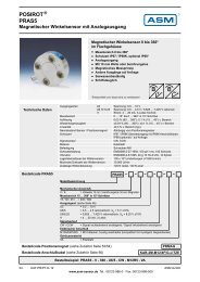
<strong>3535</strong> <strong>LCR</strong> <strong>HiTESTER</strong><br />
Component measuring instruments<br />
HEAD AMP UNIT<br />
Measure across the broad frequency range of 100kHz to 120MHz<br />
with the new Model <strong>3535</strong> <strong>LCR</strong> <strong>HiTESTER</strong>. The 6ms highspeed<br />
measurement capability is particularly useful with the builtin<br />
comparator and load functions, and for BIN (classification)<br />
measurements, to suit a wide range of applications such as chip<br />
inductor and high speed magnetic head testing, as well as other<br />
related research needs. Achieve ultimate measurement flexibility<br />
by detaching the head amp unit from the main unit and placing<br />
it in proximity to the test object so as to minimize the effect of<br />
test leads on measurements. The <strong>3535</strong>'s low price, ideal size and<br />
light weight are all achieved by incorporating an automatically<br />
balanced bridge circuit with digital control. Never before has<br />
such an advanced precision instrument coupled with economical<br />
features been placed on the test and measurement market.
1<br />
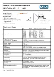
Detachable Head Amp<br />
Detach the Head Amp Unit from the <strong>3535</strong> and<br />
extend its reach to the measurement object<br />
using a dedicated cable so as to minimize the<br />
effect of measurement leads.<br />
<strong>3535</strong> MAIN UNIT<br />
9678 CONNECTION CABLE<br />
HEAD AMP UNIT<br />
Broad Frequency Measurement Range<br />
The measurement frequency is set with four-digit resolution<br />
from 100 kHz to 120 MHz.<br />
6-millisecond Minimum Measurement Time<br />
Four sampling rates can be selected: FAST, NORMAL, SLOW<br />
and SLOW2. The minimum measurement time of about 6<br />
ms (displaying |Z|) provides rapid sampling for optimum<br />
production line efficiency.<br />
(The measurement frequency range depends on the measured<br />
parameter type).<br />
14 Parameter Types<br />
The following parameters can be measured, and selected<br />
parameters can be captured using a PC. |Z|, |Y|, θ, Rp, Rs<br />
(ESR), G, X, B, Lp, Ls, Cp, Cs, D (tanδ) and Q.<br />
Adjust for Conditions While Measuring<br />
Measurement frequency, signal level and other conditions can<br />
be changed while monitoring measurement values, showing the<br />
effects of trial measurements and test condition settings.<br />
Store Measurement Data<br />
Up to 200 measurement values can be stored in the main unit.<br />
Saved values can be transferred to a computer or printed all at<br />
once.<br />
Zoom Display<br />
Up to four parameters can be displayed enlarged, for easy<br />
observation of the measurement values on production lines and<br />
in other situations where the display has to be monitored from<br />
a distance.<br />
BIN (Classification) Measurement<br />
Using up to ten classifications of two measurements, measurement<br />
values can be easily classified by rank.<br />
Continuous Measurements<br />
Store up to 30 sets of measurement conditions. Of multiple<br />
conditions stored in memory, up to five measurements can<br />
be made sequentially per condition saved on the screen.<br />
With the comparator function, the results of a sequence of<br />
measurements can be logically ANDed and output from a<br />
single instrument.<br />
Load Compensation Function<br />
A standard component can be measured to obtain a compensation<br />
amount to be applied to subsequent measurement values.<br />
This function is useful for matching measurement values<br />
between different instruments.<br />
For Changing Production Lines<br />
Utilize the ability to store up to 30 sets of measurement conditions,<br />
including comparator values, to provide rapid response to frequent<br />
component changes on flexible production lines.<br />
Simultaneously Measure up to 4 Parameters<br />
Any four of fourteen parameter types can be selected for<br />
simultaneous measurement and display.<br />
Correlation Compensation Function<br />
The constants a and b can be set in the following compensation<br />
function expression:<br />
Compensation value = a × measurement value + b<br />
Printer Output<br />
With the optional 9442 PRINTER, measurement values,<br />
comparator results and screen data can be printed.
2<br />
Automatically Balanced Bridge Circuit with Digital Control<br />
■ EXT I/O<br />
Externally control triggering and loading of measurement<br />
conditions, and for automated lines, configure output signals<br />
including comparator results and end-of-measurement signals<br />
at the touch of a button.<br />
EXT I/O Signals<br />
● Outputs<br />
• Internal DC Power (+5 V output)<br />
• Comparator Results<br />
• BIN (Classification) Measurement Results<br />
• End-of-Measurement Signal<br />
● Inputs<br />
• External DC Power Supply (+5 to 24 V can be provided by<br />
an external source)<br />
• External Trigger Signal<br />
• Selection of Panels for Loading<br />
Timing Chart for EXT I/O Sequencing<br />
The following chart shows the timing sequence of the trigger<br />
(TRIG), end-of-measurement (EOM) signals and comparator<br />
result signals from the EXT I/O connector.<br />
Minimum trigger time<br />
Minimum time from measurement<br />
completion to next trigger<br />
Circuit response time<br />
Measurement time: 6 ms∗2<br />
Previous test result Clear previous test result Test result<br />
∗ 1. α depends on the component and trigger delay.<br />
* 2. Reference value with FAST measurement speed, Averaging OFF and Z measurement selected.<br />
External Control using a PC<br />
Both RS-232C and GP-IB interfaces are included for external<br />
control of all functions (except Power ON/OFF of the <strong>3535</strong><br />
main unit) from a computer.<br />
■ RS-232C Interface<br />
Transfer Method: Communications Method:Full Duplex,<br />
Synchronization Method:Start-Stop Asynchronous<br />
Transfer Speed: 9,600 or 19,200 bps<br />
Data Length: 8 bits<br />
Parity: none<br />
Stop Bit: 1 bit<br />
Delimiter: CR+LF or CR<br />
Flow Control: none<br />
Connector: 9-pin D-sub male, reverse wired<br />
Any voltage from 100 to 240 VAC<br />
Keylock key prevents unintended operations<br />
from inadvertent touching of display panel<br />
■ GP-IB Interface<br />
Supported Standard: IEEE-488.1 1987<br />
IEEE-488.2 1987 common (required) commands can be used.<br />
GP-IB Interface<br />
RS-232C Interface<br />
EXT.I/O<br />
<strong>3535</strong> Rear View<br />
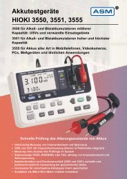
Measurement Principle<br />
Automatically Balanced Bridge Circuit with Digital Control<br />
The measurement signal is generated by a primary oscillator and applied to the component (DUT). The LOW terminal<br />
voltage is measured and used to control the phase and amplitude of a secondary oscillator so as to maintain a balanced<br />
condition (LOW terminal voltage being zero). The impedance Z and phase angle θ of the DUT<br />
are determined according to the amplitude and<br />
phase required to maintain the secondary<br />
oscillator in its balanced condition.<br />
Rout HIGH<br />
LOW Rf<br />
Zdut<br />
Primary Oscillator<br />
Secondary Oscillator<br />
CPU Bridge Circuit<br />
CPU<br />
Amplitude and Phase Control
3<br />
Changing Settings While Measuring<br />
Simple Touch Panel Operation<br />
Make all measurement condition settings from<br />
the easy-to-use touch panel. Active keys appear<br />
in reverse video, providing simple, dialog-type<br />
operation by lightly touching the item or number<br />
to be set. Real-time display of measurement<br />
data on the settings screen provide convenient<br />
monitoring while changing test signal settings.<br />
Zoom display up to 4 parameters for enhanced<br />
visibility at a distance on production lines.<br />
Note: The screens show typical examples on the <strong>3535</strong>.<br />
Initial Screen<br />
Shows measurement values for any four selected<br />
parameters, and the current setting conditions.<br />
Parameter Setting Screen<br />
Select any four of the fourteen parameter<br />
types for display.<br />
Menu Screen<br />
Select an item to display the corresponding<br />
setting screen.<br />
Measurement Frequency Setting Screen Measurement Level Setting Screen<br />
Use the numeric keypad or digit keys to enter values for changing the test frequency or<br />
level while monitoring the measurement. Choose from open-circuit voltage or constant<br />
current mode for the level setting.<br />
Load Compensation Setting Screen<br />
Set up five compensation constants for<br />
the function to correct measurement<br />
values.
4<br />
Multiple Functions for a Broad Range of Applications<br />
Comparator<br />
Compare two measurement items using the Comparator<br />
function. Input can be either the absolute value, percentage<br />
of standard value or its deviation percentage (Δ%).<br />
BIN (Classification) Measurement<br />
Classify 2 measurement items in up to 10 categories.<br />
Application<br />
Setting Screen<br />
Continuous Measurements<br />
Measurement conditions saved by the Panel Save function<br />
can be used to continuously measure up to five conditions<br />
per page.<br />
Scaling<br />
Set constants a and b to apply compensation<br />
to measurement values.<br />
Numeric Digit Display<br />
The number of significant digits of<br />
measured values of each parameter<br />
can be set to three, four or five digits.<br />
Zoom Display<br />
Enlarge the display of measurement<br />
data and comparator results.
5<br />
High Speed Testing of Chip Inductors and<br />
Magnetic Heads in Research and Development<br />
<strong>3535</strong> Specifications<br />
Measurement<br />
Items<br />
Measurement<br />
Frequency<br />
Output Impedance : 50 ±10 Ω (at 100 kHz)<br />
Measurement<br />
Signal Level<br />
: Open-terminal voltage (V) mode<br />
Level Range:<br />
5 mV to 1 V, 20 mA max. (up to 10.00 MHz)<br />
5 mV to 500 mV, 10 mA max. (above 10.01 MHz)<br />
Setting Resolution: 1mV steps<br />
Setting Accuracy: ±(5% + 5 mV) × (2 + log f)<br />
where f is in MHz<br />
Constant Current (CC) mode<br />
Level Range:<br />
200 µA to 20 mA: 1 V max. (up to 10.00 MHz)<br />
200 µA to 10 mA: 0.5 V max. (above 10.01 MHz)<br />
Setting Resolution: 10 µA steps<br />
Setting Accuracy: ±(10% + 50 µA) × (2 + log f)<br />
where f is in MHz<br />
Monitor Function : Monitor Voltage: 0.000 to 1.000 V<br />
Monitor Current: 0.000 to 20.00 mA<br />
Limit Function : Current Limit (during V setting): 0.20 to 20.00 mA<br />
Voltage Limit (during CC setting): 0.005 to 1.000 V<br />
Measurement<br />
Time<br />
Measurement<br />
Speed<br />
Average<br />
Trigger Function<br />
Load Compensation<br />
Function<br />
Key Lock<br />
Function<br />
Comparator<br />
:<br />
:<br />
Z (impedance), Y (admittance), Rs (seriesequivalent<br />
resistance, ESR), Rp (parallelequivalent<br />
resistance), G (conductivity), X<br />
(reactance), B (susceptance), θ (phase angle),<br />
Ls (series-equivalent inductance), Lp (parallelequivalent<br />
inductance), Cs (series-equivalent<br />
capacitance), Cp (parallel-equivalent capacitance),<br />
Q (Q factor), D (loss constant tanδ)<br />
Frequency Range: 100 kHz to 120 MHz<br />
Setting Resolution: Four digits (by front panel setting)*<br />
100.0 kHz to 1.000 MHz: 100-Hz steps<br />
1.000 MHz to 10.00 MHz: 1-kHz steps<br />
10.00 MHz to 100.0 MHz: 10-kHz steps<br />
100.0 MHz to 120.0 MHz: 100-kHz steps<br />
*1-Hz resolution with GP-IB or RS-232C interface<br />
Frequency Accuracy: less than ±0.005% of<br />
setting value<br />
: 6 ± 1 ms (nominal)<br />
Actual time depends on measurement conditions,<br />
such as measurement speed and averaging.<br />
: FAST, NORMAL, SLOW and SLOW2<br />
: OFF, 2, 4, 8, 16, 32 and 64<br />
: Internal and external trigger sources can be selected.<br />
Trigger Delay function:<br />
0.01 to 9.99 s with 0.01 s resolution<br />
: Measure a standard component to establish<br />
a compensation value for subsequent<br />
measurements.<br />
: Temporarily disable touch panel operation<br />
using rear panel switch.<br />
: Compares two measurement items.<br />
Input either the absolute value, percentage of<br />
standard value or its deviation percentage (Δ%).<br />
Note: for Δ%, the measurement value is<br />
displayed as the percentage of deviation<br />
from the standard value.<br />
Classification (BIN) :<br />
Measurement<br />
Correlation :<br />
Compensation Function<br />
Panel Save and<br />
Load<br />
Measurement Value<br />
Storage<br />
Zoom Display<br />
Function<br />
Continuous<br />
Measurements<br />
Audible Beeper<br />
Numerical Display<br />
Digit Setting<br />
Function<br />
Display Setting<br />
Functions<br />
Printer Functions<br />
:<br />
:<br />
:<br />
:<br />
:<br />
:<br />
:<br />
:<br />
Ranks two measurement items into ten<br />
classifications.<br />
Constants a and b are entered to compensate<br />
displayed values.<br />
[Compensated value] = a × [measurement value] + b<br />
Memory Capacity: 30 Sets<br />
Load Method: Front panel key operation,<br />
External I/O connector, GP-IB, RS-232C<br />
Memory Capacity: Up to 200 values<br />
Measurement values are stored in the main unit<br />
and transferred as a batch.<br />
Enlarge the display of measurement data and<br />
comparator results.<br />
Measurements are made continuously per<br />
conditions saved on the screen.<br />
Beeping can be set ON/OFF for key entry and<br />
comparator results (IN or NG).<br />
Measurement values can be set to display as 3,<br />
4 or 5 digits.<br />
Available settings depend on the parameter.<br />
Backlight and voltage/current monitor display<br />
can be set ON/OFF.<br />
Note: when the backlight is off, display refresh<br />
is disabled (during high-speed measurement).<br />
Hard copy printout of measurement values and<br />
screens.<br />
Note: requires 9442 and 9444<br />
Interfaces<br />
Operating<br />
Temperature and<br />
Humidity<br />
Storage<br />
Temperature and<br />
Humidity<br />
Operating<br />
Environment<br />
Power<br />
Maximum Rated<br />
Power<br />
Dimensions and Mass<br />
Conforming<br />
Standards<br />
:<br />
:<br />
:<br />
:<br />
:<br />
:<br />
:<br />
:<br />
GP-IB, RS-232C and EXT I/O (standard)<br />
10 to 40°C, 80% rh or less, no condensation<br />
-10 to 55°C, 80% rh or less, no condensation<br />
Indoors, up to 2000 m ASL<br />
100 to 240 VAC, 50/60 Hz<br />
50 VA<br />
Approx. 360W × 130H × 360D mm, 8.3 kg<br />
EMC: EN61326:1997+A1:1998+A2:2001<br />
EN61000-3-2:2000<br />
EN61000-3-3:1995+A1:2001<br />
Safety: EN61010-1:2001<br />
Pollution Degree 2
6<br />
Measurement Accuracy and Range<br />
Accuracy is calculated using Z and θ, and other parameters are calculated from these.<br />
Z Accuracy: calculated from the following formula<br />
Accuracy [%] = basic accuracy × frequency constant × level constant × measurement speed<br />
constant × cable length constant × temperature constant<br />
θ Accuracy: calculated from the following formula<br />
Accuracy [degrees] = Z accuracy × 0.6<br />
■ Basic Accuracy<br />
Measurement<br />
9700-10 HEAD AMP UNIT Upper end of range<br />
Range<br />
1 kΩ range 10 kΩ range 100 kΩ range<br />
Basic accuracy = A + B × ( Zm × 10 -1)<br />
range<br />
10 kΩ to 300 kΩ A=2.00 B=0.20<br />
Lower end of range<br />
1 kΩ to 20 kΩ A=1.00 B=0.10<br />
range<br />
Basic accuracy = A + B × ( -1)<br />
100 Ω to 2 kΩ A=0.50 B=0.10<br />
Zm × 10<br />
100 mΩ to 100 Ω A=0.50 B=0.10<br />
Zm = measurement value<br />
■ Frequency Constant<br />
log f+2 (f ≤ 10 MHz), where f is in MHz<br />
10 × log f - 7 (f > 10 MHz), where f is in MHz<br />
■ Cable Length Constant<br />
1 (0m)<br />
2 (2m, 9678)<br />
■ Measurement Speed Constant<br />
5 + 150/ V (FAST), where V is in mV<br />
3 + 100/ V (NORMAL), where V is in mV<br />
1.5 + 30/ V (SLOW), where V is in mV<br />
1 (SLOW2)<br />
■ Level Constant<br />
10 - 3 × log V, where V is in mV<br />
■ Temperature Constant<br />
1 + 0.1 | T [°C] - 23 [°C] |<br />
[Measurement Range: Reference Value]<br />
1 kΩ range 10 kΩ range 100 kΩ range<br />
Z • R* 100 Ω to 2 kΩ 1k Ω to 20 kΩ 10 kΩ to 300 kΩ<br />
C* 0.66 pF to 15.9 µF 0.066 pF to 1.59 nF 4.4 fF to 159 pF<br />
L* 0.133 nH to 3.18 mH 1.33 µH to 31.8 mH 13.3 µH to 477mH<br />
θ -180.00° to 180.00°<br />
*Ranges for R, C, and L measurement are based on the data calculated from the<br />
Z measurement range, and do not represent the guaranteed measurement ranges.<br />
● Method of Acquiring Measurement Accuracy<br />
Obtaining the basic accuracy of a<br />
capacitor. (Cs=100pF)<br />
Measurement value: Z = 159.33,<br />
θ = -87.33° when measuring with the<br />
following conditions using 1 kΩ range.<br />
• Measurement Frequency: 10 MHz<br />
• Measurement Speed: SLOW2<br />
• Measurement Signal Level: 500 mV<br />
• Cable Length: 0 m<br />
• Temperature: 24°C<br />
1. Acquire Z constants A and B from the basic<br />
accuracy table, and calculate the basic accuracy<br />
of Z.<br />
2. Acquire the other constants from the<br />
measurement conditions.<br />
3. Acquire the accuracy of Z.<br />
4. Calculate the basic accuracy of θ from the<br />
basic accuracy of Z.<br />
5. The range of possible values for Z and θ<br />
is acquired from the basic accuracy. The<br />
absolute value of θ is used.<br />
6. The range of possible values for Cs is<br />
acquired from the range of Z and θ .<br />
X = Zsinθ, Cs = 1/ ωX<br />
From the basic accuracy table, the constants A and B are A = 0.50 and B = 0.10<br />
159.33 × 10<br />
Z basic accuracy = 0.50 + 0.10 × ( - 1) = ±0.559%<br />
1000<br />
Frequency constant = log(10) + 2 = 3<br />
Level constant = 10 - 3 × log(500) ≈ 1.903<br />
Measurement Speed constant = 1<br />
Cable Length constant = 1<br />
Temperature constant = 1 + 0.1 × |24 - 23| = 1.1<br />
Z accuracy = 0.559 × 3 × 1.903 × 1 × 1 × 1.1 ≈ ±3.510%<br />
θ accuracy = 3.510 × 0.6 = ±2.106°<br />
Zmin = 159.33 × ( 1 - 3.510 / 100 ) ≈ 153.74Ω<br />
Zmax = 159.33 × ( 1 + 3.510 / 100 ) ≈ 164.92Ω<br />
θmin = 87.33 - 2.106 ≈ 85.224°<br />
θmax =87.33 + 2.106 ≈ 89.436°<br />
Csmin = 1 ÷ ( ω × Zmax × sinθmax ) ≈ 96.509 pF ...-3.491%<br />
Csmax = 1 ÷ ( ω × Zmin × sinθmin ) ≈ 103.883 pF ...3.883%<br />
ω = 2 × π × f, where f is the measurement frequency in Hz<br />
Therefore, the basic accuracy of Cs is -3.491 to 3.883%.
7<br />
Options<br />
Head Amp Unit must be factory adjusted for dedicated use with the <strong>3535</strong><br />
before delivery.<br />
9700-10 HEAD AMP UNIT<br />
Measurement Range: 100 mΩ to 300 kΩ(3 ranges)<br />
For testing components with<br />
electrodes on the bottom<br />
9678 CONNECTION CABLE<br />
Cable Length: 2m<br />
SMD TEST FIXTURE<br />
(direct contact type)<br />
9677 SMD TEST FIXTURE<br />
Operating Frequency : DC to 120 MHz<br />
Measurable Object Size : 3.5 ±0.5 mm<br />
Dimensions : Approx.103W × 37.1H × 47.6D mm<br />
Mass : Approx. 135 g<br />
*Please note that use of the 9677 with Model <strong>3535</strong> will NOT<br />
comply with CE mark requirements.<br />
9699 SMD TEST FIXTURE<br />
Operating Frequency : DC to 120 MHz<br />
Measurable Object Size :<br />
Width: 1.0 to 4.0mm; Height: less than 1.5mm<br />
Dimensions : Approx.100.5W×28.6H×40.0Dmm<br />
Mass : Approx. 125 g<br />
9442 PRINTER<br />
Printing Method : Thermal serial dot printer<br />
Paper Width / Print Speed : 112 mm / 52.5 cps<br />
Power Supply : 9443 AC Adapter or supplied NiMH battery<br />
(prints 3000 lines after full charge by 9443)<br />
Dimensions : Approx. 160W × 66.5H × 170D mm<br />
Mass : Approx. 580 g<br />
Note: the 9444 Connection Cable and AC Adapter are required to connect the 9442 Printer.<br />
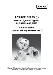
<strong>3535</strong> <strong>LCR</strong> <strong>HiTESTER</strong><br />
The Head Amp and Test Fixtures are not supplied with the unit.<br />
Please order the appropriate options for your application.<br />
● Options<br />
9700-10 HEAD AMP UNIT<br />
9677 SMD TEST FIXTURE<br />
9699 SMD TEST FIXTURE<br />
9678 CONNECTION CABLE<br />
9637 RS-232C CABLE (9pin-9pin/cross/1.8m)<br />
9638 RS-232C CABLE (9pin-25pin/cross/1.8m)<br />
Head Amp Unit must be factory adjusted for dedicated use with the<br />
<strong>3535</strong> before delivery.<br />
9151-02 GP-IB CONNECTION CABLE (2 m)<br />
9151-04 GP-IB CONNECTION CABLE (4 m)<br />
9442 PRINTER<br />
9443-02 AC ADAPTER (for 9442, EU)<br />
9443-03 AC ADAPTER (for 9442, USA)<br />
9444 CONNECTION CABLE (for 9442)<br />
1196 RECORDING PAPER (for 9442 / 25 m, 10 rolls)<br />
DISTRIBUTED BY<br />
HEAD OFFICE :<br />
81 Koizumi, Ueda, Nagano, 386-1192, Japan<br />
TEL +81-268-28-0562 / FAX +81-268-28-0568<br />
E-mail: os-com@hioki.co.jp<br />
HIOKI USA CORPORATION :<br />
6 Corporate Drive, Cranbury, NJ 08512 USA<br />
TEL +1-609-409-9109 / FAX +1-609-409-9108<br />
E-mail: hioki@hiokiusa.com<br />
Shanghai Representative Office :<br />
1310 Shanghai Times Square Office<br />
93 Huaihai Zhong Road<br />
Shanghai, 200021, P.R.China<br />
TEL +86-21-6391-0090, 0092<br />
FAX +86-21-6391-0360<br />
E-mail: info@hioki.cn<br />
All information correct as of Apr. 26, 2006. All specifications are subject to change without notice. <strong>3535</strong>E4-64E-03P Printed in Japan