Plug-in relays Micro ISO relays
Plug-in relays Micro ISO relays
Plug-in relays Micro ISO relays

Create successful ePaper yourself
Turn your PDF publications into a flip-book with our unique Google optimized e-Paper software.
<strong>Plug</strong>-<strong>in</strong> <strong>relays</strong><br />
<strong>Micro</strong> <strong>ISO</strong> <strong>relays</strong><br />
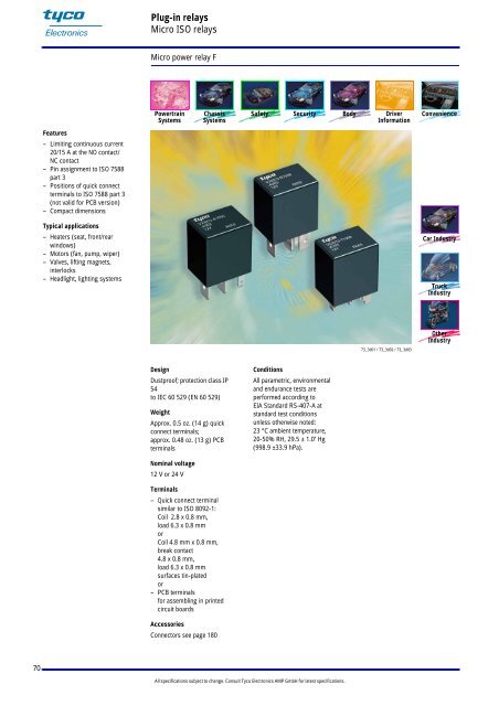
<strong>Micro</strong> power relay F<br />
Powertra<strong>in</strong><br />
Systems<br />
Chassis<br />
Systems<br />
Safety Security Body Driver<br />
Information<br />
Convenience<br />
Features<br />
– Limit<strong>in</strong>g cont<strong>in</strong>uous current<br />
20/15 A at the NO contact/<br />
NC contact<br />
– P<strong>in</strong> assignment to <strong>ISO</strong> 7588<br />
part 3<br />
– Positions of quick connect<br />
term<strong>in</strong>als to <strong>ISO</strong> 7588 part 3<br />
(not valid for PCB version)<br />
– Compact dimensions<br />
Typical applications<br />
– Heaters (seat, front/rear<br />
w<strong>in</strong>dows)<br />
– Motors (fan, pump, wiper)<br />
– Valves, lift<strong>in</strong>g magnets,<br />
<strong>in</strong>terlocks<br />
– Headlight, light<strong>in</strong>g systems<br />
Car Industry<br />
Truck<br />
Industry<br />
Other<br />
Industry<br />
73_3d01 / 73_3d02 / 73_3d03<br />
Design<br />
Dustproof; protection class IP<br />
54<br />
to IEC 60 529 (EN 60 529)<br />
Weight<br />
Approx. 0.5 oz. (14 g) quick<br />
connect term<strong>in</strong>als;<br />
approx. 0.48 oz. (13 g) PCB<br />
term<strong>in</strong>als<br />
Conditions<br />
All parametric, environmental<br />
and endurance tests are<br />
performed accord<strong>in</strong>g to<br />
EIA Standard RS-407-A at<br />
standard test conditions<br />
unless otherwise noted:<br />
23 °C ambient temperature,<br />
20-50% RH, 29.5 ± 1.0" Hg<br />
(998.9 ±33.9 hPa).<br />
Nom<strong>in</strong>al voltage<br />
12 V or 24 V<br />
Term<strong>in</strong>als<br />
– Quick connect term<strong>in</strong>al<br />
similar to <strong>ISO</strong> 8092-1:<br />
Coil 2.8 x 0.8 mm,<br />
load 6.3 x 0.8 mm<br />
or<br />
Coil 4.8 mm x 0.8 mm,<br />
break contact<br />
4.8 x 0.8 mm,<br />
load 6.3 x 0.8 mm<br />
surfaces t<strong>in</strong>-plated<br />
or<br />
– PCB term<strong>in</strong>als<br />
for assembl<strong>in</strong>g <strong>in</strong> pr<strong>in</strong>ted<br />
circuit boards<br />
Accessories<br />
Connectors see page 180<br />
70<br />
All specifications subject to change. Consult Tyco Electronics AMP GmbH for latest specifications.
<strong>Plug</strong>-<strong>in</strong> <strong>relays</strong><br />
<strong>Micro</strong> <strong>ISO</strong> <strong>relays</strong><br />
<strong>Micro</strong> power relay F<br />
Dimension draw<strong>in</strong>g<br />
Version with quick connect term<strong>in</strong>als<br />
for push-on connectors 2.8 mm and 6.3 mm<br />
Version with quick connect term<strong>in</strong>als<br />
for push-on connectors 4.8 mm and 6.3 mm<br />
.602 ±.008<br />
(15.3 ±0.2)<br />
.799 ±.008<br />
(20.3 ±0.2)<br />
.602 ±.008<br />
(15.3 ±0.2)<br />
.799 ±.008<br />
(20.3 ±0.2)<br />
.898 ±.008<br />
(22.8 ±0.2)<br />
.898 ±.008<br />
(22.8 ±0.2)<br />
ø .065 +.008<br />
(ø 1.65 +0.2)<br />
.248 ±.004<br />
(6.3 ±0.1)<br />
.433 ±.020<br />
(11 ± 0.5)<br />
.374 MAX<br />
(9.5)<br />
ø .051 +.008<br />
(ø 1.3 +0.2)<br />
Quick connect term<strong>in</strong>al similar to <strong>ISO</strong> 8092-1<br />
View on the term<strong>in</strong>als (bottom view)<br />
View on the term<strong>in</strong>als (bottom view)<br />
.591 ±.006<br />
(15 ±0.15)<br />
.110 ±.004<br />
(2.8 ±0.1)<br />
.031 ±.002<br />
(0.8 ±0.05)<br />
ECR0571-M<br />
.098 ±.006<br />
(2.5 ±0.15)<br />
ø .065 +.008<br />
(ø 1.65 +0.2)<br />
.248 ±.004<br />
(6.3 ±0.1)<br />
.433 ±.020<br />
(11 ± 0.5)<br />
ø .051 +.008<br />
(ø 1.3 +0.2)<br />
Quick connect term<strong>in</strong>al similar to <strong>ISO</strong> 8092-1<br />
View on the term<strong>in</strong>als Term<strong>in</strong>al (bottom arrangement view)<br />
View of the term<strong>in</strong>als<br />
.551 ±.006<br />
(14 ±0.15)<br />
.189 ±.004<br />
(4.8 ±0.1)<br />
.031 ±.002<br />
(0.8 ±0.05)<br />
ECR0569-B<br />
.098 ±.006<br />
(2.5 ±0.15)<br />
.354 ±.006<br />
(9 ±0.15)<br />
ECR0572-V<br />
.354 ±.006<br />
(9 ±0.15)<br />
ECR1079-S<br />
.413 ±.006<br />
(10.5 ±0.15)<br />
.413 ±.006<br />
(10.5 ±0.15)<br />
Version with PCB term<strong>in</strong>als<br />
.602 ±.008<br />
(15.3 ±0.2)<br />
.799 ±.008<br />
(20.3 ±0.2)<br />
.898 ±.008<br />
(22.8 ±0.2)<br />
.126 ±.004<br />
(3.2 ± 0.1)<br />
1 x 30°<br />
.248 ±.004<br />
(6.3 ±0.1)<br />
.085 ±.006<br />
(2.15 ±0.15) .085 ±.006<br />
(2.15 ±0.15)<br />
.031 ±.002<br />
(0.8 ±0.05)<br />
.079 -.020<br />
(2.5 - 0.5)<br />
.079 MIN<br />
(2)<br />
Term<strong>in</strong>als<br />
t<strong>in</strong>ned<br />
ECR0559-4<br />
View on the term<strong>in</strong>als (bottom view)<br />
Mount<strong>in</strong>g holes<br />
View on the term<strong>in</strong>als (bottom view)<br />
.051 ±.004<br />
(1.2 ±0.1)<br />
.098<br />
(2.5)<br />
.354 ±.002<br />
(9 ±0.05)<br />
.102 ±.004<br />
(2.6 ±0.1)<br />
ECR2113-G<br />
.591 ±.002<br />
(15 ±0.05)<br />
.315 ±.002<br />
(8 ±0.05)<br />
ECR0561-F<br />
71<br />
All specifications subject to change. Consult Tyco Electronics AMP GmbH for latest specifications.
<strong>Plug</strong>-<strong>in</strong> <strong>relays</strong><br />
<strong>Micro</strong> <strong>ISO</strong> <strong>relays</strong><br />
<strong>Micro</strong> power relay F<br />
Contact data<br />
Contact configuration<br />
Contact material<br />
Circuit symbol<br />
(see also P<strong>in</strong> assignment)<br />
Make contact/<br />
Form A<br />
AgNi0.15<br />
Break contact/<br />
Form B<br />
Max. switch<strong>in</strong>g voltage<br />
See load limit curve<br />
Max. switch<strong>in</strong>g power<br />
See load limit curve<br />
Max. switch<strong>in</strong>g current 1)<br />
On 2)<br />
Off<br />
90 A<br />
30 A<br />
20 A<br />
15 A<br />
Limit<strong>in</strong>g cont<strong>in</strong>uous current at 23 °C<br />
20 A<br />
15 A<br />
at 85 °C<br />
15 A<br />
10 A<br />
Voltage drop (<strong>in</strong>itial) at 10 A Typ. 20 mV Typ. 40 mV<br />
Increase <strong>in</strong> coil temperature at 10 A load Typ. 15 °C<br />
Mechanical endurance (without load)<br />
Typ. 10 7 operations<br />
Electrical endurance with 10 A load current 1) > 5 x 10 5 operations > 2 x 10 5 operations<br />
1)<br />
The values apply to a resistive load or <strong>in</strong>ductive load with suitable spark suppression.<br />
2)<br />
This current may flow for a maximum of 3 sec for a make/break ratio of 1 : 10.<br />
Load limit curve<br />
Load limit curve 1 arc<br />
ext<strong>in</strong>guishes dur<strong>in</strong>g transit time<br />
Load limit curve 2 safe<br />
shutdown, no stationary arc<br />
P<strong>in</strong> assignment<br />
1 make contact/ 1 break contact/<br />
1 form A 1 form B<br />
Models with resistor or<br />
diode <strong>in</strong> parallel to the<br />
coil on request.<br />
Models with resistor or<br />
diode <strong>in</strong> parallel to the<br />
coil on request.<br />
72<br />
All specifications subject to change. Consult Tyco Electronics AMP GmbH for latest specifications.
<strong>Plug</strong>-<strong>in</strong> <strong>relays</strong><br />
<strong>Micro</strong> <strong>ISO</strong> <strong>relays</strong><br />
<strong>Micro</strong> power relay F<br />
Coil data<br />
Available for nom<strong>in</strong>al voltages<br />
12, 24 VDC<br />
Nom<strong>in</strong>al power consumption of the unsuppressed coil at nom<strong>in</strong>al voltage<br />
1.16 W<br />
Test voltage w<strong>in</strong>d<strong>in</strong>g/contact<br />
500 VAC rms<br />
Upper limit temperature for the coil 180 °C<br />
Maximum ambient temperature range 1)<br />
– 40 to + 125 °C<br />
Max. switch<strong>in</strong>g rate without contact load<strong>in</strong>g<br />
20 Hz<br />
Operate time 2)<br />
Typ. 6 msec<br />
Release time 2)<br />
Typ. 3 msec<br />
1)<br />
See also operat<strong>in</strong>g voltage range diagram<br />
2)<br />
Measured at nom<strong>in</strong>al voltage without coil suppression unit<br />
N.B.<br />
A low resistive device <strong>in</strong> parallel to the relay coil slows the armature movement down<br />
and reduces the lifetime caused by <strong>in</strong>creased erosion and/or higher risk of contact tack weld<strong>in</strong>g.<br />
Operat<strong>in</strong>g voltage range<br />
Does not take <strong>in</strong>to account<br />
the temperature rise due to<br />
the contact current<br />
E = pre-energization<br />
Mechanical data<br />
Cover retention<br />
pull<br />
push<br />
Term<strong>in</strong>als<br />
Pull force<br />
Push force<br />
Resistance to bend<strong>in</strong>g, force applied to front<br />
Resistance to bend<strong>in</strong>g, force applied to side<br />
Torsion<br />
Enclosures<br />
Dust cover<br />
100 N (22.5 lbs)<br />
100 N (22.5 lbs)<br />
100 N (22.5 lbs)<br />
100 N (22.5 lbs)<br />
10 N (2.25 lbs) 1)<br />
10 N (2.25 lbs) 1)<br />
0.3 Nm<br />
Protects relay from dust. For use <strong>in</strong> passenger compartment or enclosures<br />
1)<br />
Values apply 2 mm from the end of the term<strong>in</strong>al. When the force is removed, the term<strong>in</strong>al must not have moved by more than 0.3 mm.<br />
73<br />
All specifications subject to change. Consult Tyco Electronics AMP GmbH for latest specifications.
<strong>Plug</strong>-<strong>in</strong> <strong>relays</strong><br />
<strong>Micro</strong> <strong>ISO</strong> <strong>relays</strong><br />
<strong>Micro</strong> power relay F<br />
Operat<strong>in</strong>g conditions<br />
Temperature range, storage -40 °C to 155 °C<br />
Test Relevant standard Test<strong>in</strong>g as per Dimension Comments<br />
Climatic cycl<strong>in</strong>g with condensation EN <strong>ISO</strong> 6988 6 cycles Storage 8/16 h<br />
Temperature cycl<strong>in</strong>g IEC 60 068-2-14 Nb 10 cycles – 40/+ 85 °C (5 °C per m<strong>in</strong>.)<br />
Damp heat<br />
cyclic<br />
IEC 60 068-2-30 Db, Variant 1<br />
6 cycles<br />
Upper air temperature 55 °C<br />
constant<br />
IEC 60 068-2-3<br />
Ca<br />
10 days<br />
Corrosive gas IEC 60 068-2-42<br />
IEC 60 068-2-43<br />
10 ± 2 cm 3 /m 3 SO 2<br />
1 ± 0.3 cm 3 /m 3 H 2 S<br />
10 days<br />
10 days<br />
Vibration resistance<br />
IEC 60 068-2-6 (s<strong>in</strong>e pulse form)<br />
acceleration, acc. to position<br />
20 - 200 Hz<br />
m<strong>in</strong>. 5 g<br />
No change <strong>in</strong> the<br />
switch<strong>in</strong>g state > 10 µsec<br />
Shock resistance IEC 60 068-2-27 (half-s<strong>in</strong>e pulse form)<br />
acceleration, acc. to position<br />
m<strong>in</strong>. 10 g<br />
No change <strong>in</strong> the<br />
switch<strong>in</strong>g state > 10 µsec<br />
Solderability (PCB version) IEC 60 068-2-20 Ta, Method 1 Ag<strong>in</strong>g 3 (4 h/155 °C), dewett<strong>in</strong>g<br />
Resistance to solder<strong>in</strong>g heat IEC 60 068-2-20 Tb, Method 1 10 sec ±1 sec with shield<strong>in</strong>g<br />
Load dump <strong>ISO</strong> 7637 DIN 40 839 Part 1<br />
Jump start<br />
5 s 16 V<br />
3 cycles<br />
15 s 28 V<br />
10 s 16 V<br />
Drop test<br />
Capable of meet<strong>in</strong>g specifications after 1.0 m (3.28 foot) drop onto concrete<br />
Flammability<br />
UL94-HB<br />
Order<strong>in</strong>g <strong>in</strong>formation<br />
Part number<br />
(Replace * with<br />
“Coil designator”)<br />
Contact<br />
arrangement<br />
Contact<br />
material Enclosure Term<strong>in</strong>als<br />
V23073-A1*-A301 1 Form B AgNi0.15 dust cover quick connect, 2.8 mm and 6.3 mm<br />
V23073-A1*-A302 1 Form A AgNi0.15 dust cover quick connect, 2.8 mm and 6.3 mm<br />
V23073-B1*-A301 1 Form B AgNi0.15 dust cover quick connect, 4.8 mm and 6.3 mm<br />
V23073-B1*-A302 1 Form A AgNi0.15 dust cover quick connect, 4.8 mm and 6.3 mm<br />
V23073-C1*-A301 1 Form B AgNi0.15 dust cover pr<strong>in</strong>ted circuit<br />
V23073-C1*-A302 1 Form A AgNi0.15 dust cover pr<strong>in</strong>ted circuit<br />
Coil versions<br />
Coil<br />
designator<br />
Rated coil<br />
voltage<br />
(V)<br />
Coil<br />
resistance<br />
+/- 10%<br />
(Ω)<br />
Must<br />
operate<br />
voltage<br />
(VDC)<br />
Must<br />
release<br />
voltage<br />
(VDC)<br />
Allowable overdrive<br />
(VDC)<br />
at 23 °C 1)<br />
005 12 124 7.2 1.3 23 18<br />
006 24 489 14.4 2.8 47 35<br />
1)<br />
Allowable overdrive is stated with no load current flow<strong>in</strong>g through the relay contacts and m<strong>in</strong>imum coil resistance.<br />
at 85 °C 1)<br />
Standard delivery pack (orders <strong>in</strong> multiples of delivery pack)<br />
<strong>Micro</strong> power relay F:<br />
675 pieces<br />
74<br />
All specifications subject to change. Consult Tyco Electronics AMP GmbH for latest specifications.
![[pdf] tms](https://img.yumpu.com/51237219/1/190x245/pdf-tms.jpg?quality=85)