Handy Dri - Heat and Plumb
Handy Dri - Heat and Plumb
Handy Dri - Heat and Plumb

Create successful ePaper yourself
Turn your PDF publications into a flip-book with our unique Google optimized e-Paper software.
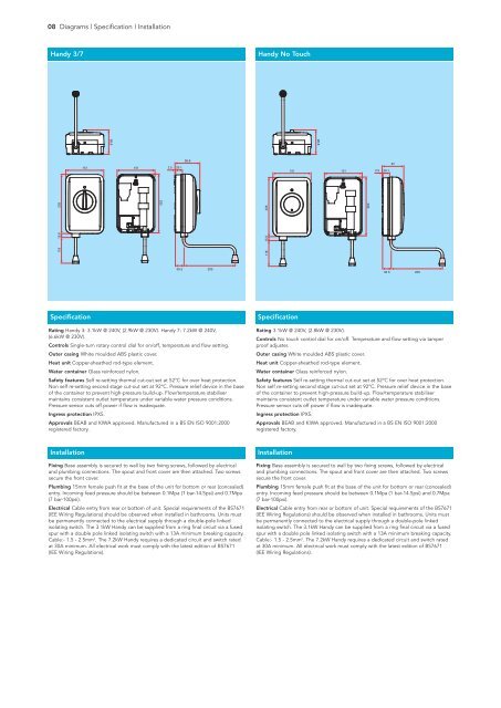
08 Diagrams | Specification | Installation<br />
<strong>H<strong>and</strong>y</strong> 3/7<br />
<strong>H<strong>and</strong>y</strong> No Touch<br />
96.8<br />
96.8<br />
96.8<br />
151 151<br />
151 151<br />
2.5<br />
2.5<br />
96.8<br />
29.1 96.8<br />
29.1<br />
151 151<br />
2.5<br />
29.1<br />
87<br />
118 15.6 118 15.6<br />
235<br />
235<br />
118 15.6<br />
235<br />
235<br />
235<br />
235<br />
35.5 205<br />
35.5 205<br />
35.5 205<br />
Specification<br />
Rating <strong>H<strong>and</strong>y</strong> 3: 3.1kW @ 240V, (2.9kW @ 230V). <strong>H<strong>and</strong>y</strong> 7: 7.2kW @ 240V,<br />
(6.6kW @ 230V).<br />
Controls Single-turn rotary control dial for on/off, temperature <strong>and</strong> flow setting.<br />
Outer casing White moulded ABS plastic cover.<br />
<strong>Heat</strong> unit Copper-sheathed rod-type element.<br />
Water container Glass reinforced nylon.<br />
Safety features Self re-setting thermal cut-out set at 52°C for over heat protection.<br />
Non self re-setting second stage cut-out set at 92°C. Pressure relief device in the base<br />
of the container to prevent high-pressure build-up. Flow/temperature stabiliser<br />
maintains consistent outlet temperature under variable water pressure conditions.<br />
Pressure sensor cuts off power if flow is inadequate.<br />
Ingress protection IPX5.<br />
Approvals BEAB <strong>and</strong> KIWA approved. Manufactured in a BS EN ISO 9001:2000<br />
registered factory.<br />
Specification<br />
Rating 3.1kW @ 240V, (2.8kW @ 230V).<br />
Controls No touch control dial for on/off. Temperature <strong>and</strong> flow setting via tamper<br />
proof adjuster.<br />
Outer casing White moulded ABS plastic cover.<br />
<strong>Heat</strong> unit Copper-sheathed rod-type element.<br />
Water container Glass reinforced nylon.<br />
Safety features Self re-setting thermal cut-out set at 52°C for over heat protection.<br />
Non self re-setting second stage cut-out set at 92°C. Pressure relief device in the base<br />
of the container to prevent high-pressure build-up. Flow/temperature stabiliser<br />
maintains consistent outlet temperature under variable water pressure conditions.<br />
Pressure sensor cuts off power if flow is inadequate.<br />
Ingress protection IPX5.<br />
Approvals BEAB <strong>and</strong> KIWA approved. Manufactured in a BS EN ISO 9001:2000<br />
registered factory.<br />
Installation<br />
Fixing Base assembly is secured to wall by two fixing screws, followed by electrical<br />
<strong>and</strong> plumbing connections. The spout <strong>and</strong> front cover are then attached. Two screws<br />
secure the front cover.<br />
<strong>Plumb</strong>ing 15mm female push fit at the base of the unit for bottom or rear (concealed)<br />
entry. Incoming feed pressure should be between 0.1Mpa (1 bar-14.5psi) <strong>and</strong> 0.7Mpa<br />
(7 bar-100psi).<br />
Electrical Cable entry from rear or bottom of unit. Special requirements of the BS7671<br />
(IEE Wiring Regulations) should be observed when installed in bathrooms. Units must<br />
be permanently connected to the electrical supply through a double-pole linked<br />
isolating switch. The 3.1kW <strong>H<strong>and</strong>y</strong> can be supplied from a ring final circuit via a fused<br />
spur with a double pole linked isolating switch with a 13A minimum breaking capacity.<br />
Cable:- 1.5 - 2.5mm 2 . The 7.2kW <strong>H<strong>and</strong>y</strong> requires a dedicated circuit <strong>and</strong> switch rated<br />
at 30A minimum. All electrical work must comply with the latest edition of BS7671<br />
(IEE Wiring Regulations).<br />
Installation<br />
Fixing Base assembly is secured to wall by two fixing screws, followed by electrical<br />
<strong>and</strong> plumbing connections. The spout <strong>and</strong> front cover are then attached. Two screws<br />
secure the front cover.<br />
<strong>Plumb</strong>ing 15mm female push fit at the base of the unit for bottom or rear (concealed)<br />
entry. Incoming feed pressure should be between 0.1Mpa (1 bar-14.5psi) <strong>and</strong> 0.7Mpa<br />
(7 bar-100psi).<br />
Electrical Cable entry from rear or bottom of unit. Special requirements of the BS7671<br />
(IEE Wiring Regulations) should be observed when installed in bathrooms. Units must<br />
be permanently connected to the electrical supply through a double-pole linked<br />
isolating switch. The 3.1kW <strong>H<strong>and</strong>y</strong> can be supplied from a ring final circuit via a fused<br />
spur with a double pole linked isolating switch with a 13A minimum breaking capacity.<br />
Cable:- 1.5 - 2.5mm 2 . The 7.2kW <strong>H<strong>and</strong>y</strong> requires a dedicated circuit <strong>and</strong> switch rated<br />
at 30A minimum. All electrical work must comply with the latest edition of BS7671<br />
(IEE Wiring Regulations).