Ergo-Pro Single line solar station - Heat and Plumb
Ergo-Pro Single line solar station - Heat and Plumb
Ergo-Pro Single line solar station - Heat and Plumb

You also want an ePaper? Increase the reach of your titles
YUMPU automatically turns print PDFs into web optimized ePapers that Google loves.
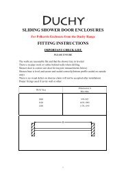
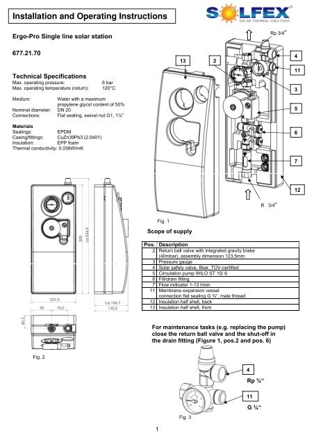
Installation <strong>and</strong> Operating Instructions<strong>Ergo</strong>-<strong>Pro</strong> <strong>Single</strong> <strong>line</strong> <strong>solar</strong> <strong>station</strong>Rp 3/4“677.21.701324Technical SpecificationsMax. operating pressure:6 barMax. operating temperature (return): 120°C113Medium:Water with a maximumpropylene glycol content of 50%Nominal diameter: DN 20Connections: Flat sealing, swivel nut G1, 1¼”5MaterialsSealings:EPDMCasing/fittings: CuZn39Pb3 (2.0401)Insulation: EPP foamThermal conductivity: 0.038W/mK6712Rp 3/4“Fig. 1Scope of supplyPos. Description2 Return ball valve with integrated gravity brake(40mbar), assembly dimension 123,5mm3 Pressure gauge4 Solar safety valve, 6bar, TÜV-certified5 Circulation pump WILO ST 15/ 66 Fill/drain fitting7 Flow indicator 1-13 l/min11 Membrane expansion vesselconnection flat sealing G ¾“, male thread12 Insulation half shell, back13 Insulation half shell, frontFor maintenance tasks (e.g. replacing the pump)close the return ball valve <strong>and</strong> the shut-off inthe drain fitting (Figure 1, pos.2 <strong>and</strong> pos. 6)Fig. 24RRp ¾“11GG ¾“Fig. 31
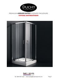
Function of the Gravity Brake (Pos. 2)Opening pressure of the gravity brake: 40 mbarThe gravity brake in integrated in the return ball valve.It is operated by turning the h<strong>and</strong>le of the ball valve.Fig. 4a: Ball valve open Fig. 4b: Gravity brake open Fig. 4c: Ball valve closedTo prevent gravity circulation, thevalve disc should not bevented. The gravity brake is inoperating position (closed).The slots in the h<strong>and</strong>le are in avertical position (Figure 4a).To fill <strong>and</strong> completely empty the<strong>solar</strong> system, open thegravity brake by turning the h<strong>and</strong>leto the right.The slots in the h<strong>and</strong>le arepositioned at an angle of 45°(Figure 4b).Turn the h<strong>and</strong>le to the right by atotal of 90°.The slots in the h<strong>and</strong>le are in ahorizontal position.The ball valve is closed (Figure 4c).Fill/Drain Fitting (Pos. 6)Use the fill <strong>and</strong> drainvalves on the fill/drainfitting to fill <strong>and</strong> drainthe <strong>solar</strong> system(Figure 5a).To drain the system, theslot in the spindle mustbe in a horizontalposition (Figure 5b).Fig 5aFig 5bFlow Indicator (Pos.7)The adjustment of the flow rate of the thermal carrier mediumtakes place by controlling the speed levels (I, II, III) of thecirculation pump <strong>and</strong> the throttle in the fill/drain fitting(Figure 5).The flow indicator shows the set flow rate (Figure 6).The indicator range is between 1 <strong>and</strong> 13l/min.Read volume flow values atthis edge of the rotameterFig. 62
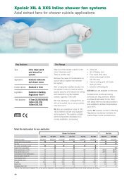
WallmountingFig 73
Extract from the Installation <strong>and</strong> Maintenance Instructions of the pumpEC declaration of conformityWe hereby declare that this unitcomplies with the following relevantprovisions:EG machinery directive89/392/EWG in this version,91/368/EWG, 93/44/EWG,93/68/EWGResistance to electromagnetism89/336/EWG in this version92/31/EWG, 93/68/EWGApplied harmonized st<strong>and</strong>ards inparticular:EN 809, EN 50 081-1, EN 50 082-1,EN 50 081-2, EN 50 082-2.Safety precautions for the operator1. GeneralInstallation <strong>and</strong> service by qualified personnel only1.1 Fields of applicationType: ST: for <strong>solar</strong> thermal systems1.2 Connection <strong>and</strong> output dataMinimum input pressure at the air intake*at temperatures + 50°C:0,05 barat temperatures + 95°C:0,3 barat temperatures +110°C:1,0 barPermissible temperature range: -10°C up to + 110°CMaximum permissible ambient temperature: +40°C*These values are valid up to 300m above sea level.For higher elevations add: 0,01 bar/100m .4
The minimum inlet pressure must be maintained in order to avoid cavitations’ noise.Permissible fluids:Water <strong>and</strong> water/glycol mixtures up to a ratio of 1:1. Glycol mixtures require a reassessmentof pump hydraulic data in <strong>line</strong> with the increased viscosity <strong>and</strong> depending on mixing ratios.Only approved marks of additives with corrosion inhibitors must be used in strict compliancewith manufacturers´ instructions.2. Safety Rules2.1 Safety Rules For The OperatorLocal regulations for the prevention of accidents must be observed. Danger from electricalenergy must be excluded (conforming to local or general regulations such as IEC, VDE, etc.)2.2 Safety Rules for Inspections <strong>and</strong> Installation WorkIt is the operator´s responsibility to ensure that inspections <strong>and</strong> installation work are carriedout by authorized <strong>and</strong> qualified personnel only, having themselves made fully conversantwith these instructions. Work must principally be carried out only with the plant switched off<strong>and</strong> at complete st<strong>and</strong>still.2.3 Abnormal Operating ConditionsOperational safety of the plant is only ensured if used in accordance with these instructions.The limits stated there must not be exceeded under any circumstances.3. Description of <strong>Pro</strong>duct <strong>and</strong> AccessoriesThe pump ST/STL is a <strong>solar</strong> thermal pump with special hydraulic (pump housing coated) forusing in <strong>solar</strong> thermal systems. Motor overload protection is not required. The motoroperates non-overloading. Speed setting: All pumps are equipped with a rotary switch in theterminal box to enable manual 3-speed control (1 = min) (2-3 = max). At minimum speed themaximum speed is reduced to approx. 40…50%. The power input is reduced toapproximately 50%.4. Sitting/Installation4.1 Installation- Direction of fluid flow must correspond with the arrow on the pump housing(Fig. 2, pos. 1).- If using pump housings with integrated exhaust cavity it must be observed that theconnection for the vent or the vent pipe is vertical (12h position).- When connecting the pump to the conduit of pipes, the pump can be secured againsttwisting using a spanner on the key surfaces which have been created for thispurpose (Fig. 3)4.2 Electrical wiring- Cable leads to be routed in such a way to avoid any contact with pipe work <strong>and</strong>/orpump or stator housings.- Check that the mains current <strong>and</strong> voltage comply with the data on the rating plate.- Effect all wiring according to Wiring diagram (Fig. 4).- Pump/installation must be earthed in compliance with regulations.5
5. Commissioning5.1 System filling <strong>and</strong> ventingThe pump is normally vented automatically after a short operational period. Short-termdry-running will not harm the pump. Direct venting of the pump, if necessary, is doneaccording to the following procedure:- Switch off the pump,- close discharge isolating valve,- carefully slacken <strong>and</strong> remove the vent plug (Fig. 5).Beware of possibly released hot liquid or vapour, depending on fluidtemperature <strong>and</strong> system pressure.Danger of scalding exists!- Carefully move pump shaft several times by means of screwdriver, - protect electricalparts from leaking water- Switch-on the pump- After 15…30 sec close vent plug again,- open isolating valve again.ATTENTION!It is possible that the pump shaft jams with the vent plug open, depending onsystem pressure. The pump can become extremely hot, depending on theoperational state of the pump or the pipe system (fluid temperature).Danger of scalding exists when touching the pump!6