ESP Classic 15kW, 17kW and 25kW Installation ... - Heat & Plumb
ESP Classic 15kW, 17kW and 25kW Installation ... - Heat & Plumb
ESP Classic 15kW, 17kW and 25kW Installation ... - Heat & Plumb

Create successful ePaper yourself
Turn your PDF publications into a flip-book with our unique Google optimized e-Paper software.
<strong>ESP</strong> <strong>Classic</strong><strong>15kW</strong>, <strong>17kW</strong> <strong>and</strong> <strong>25kW</strong><strong>Installation</strong> ManualEarth Save Products Ltd©<strong>ESP</strong> Oct2009
CONTENT1 Preface 22 Safety Precaution 3(1) Mark notes 3(2) Icon notes 3(3) Warning 4(4) Attention 43 Specification 5(1) Appearance <strong>and</strong> Structure of the heat pump 5(2) Specification data 5(3) Unit dimension 64 <strong>Installation</strong> 6(1) Application of heat pump 6(2) Choose a right heat pump unit 7(3) <strong>Installation</strong> place 7(4) <strong>Installation</strong> method 7(5) Water loop connection 7(6) Power supply connection 7(7) Location of the unit 8(8) Transit 8(9) Trial running 85 Usage 9(1) Wire controller function 9(2) How to use the remote controller 96 Maintenance 12(1) Maintenance 12(2) Ordinary malfunctions <strong>and</strong> solution 127 Appendix 14(1) Appendix 1 14(2) Appendix 2 14(3) Appendix 3 14(4) Appendix 4 14(5) Appendix 5 14(6) Appendix 6 15Preface Congratulations on purchasing your <strong>ESP</strong> <strong>Classic</strong> Series air source heat pump (“ASHP”) fromEarth Save Products Ltd. (“<strong>ESP</strong>”) <strong>and</strong> thank you for entrusting the heat of your home to one ofour units. In line with our policy of providing high quality, durable products with market leading technology,the <strong>ESP</strong> <strong>Classic</strong> Series air source heat pumps has been developed using strict design <strong>and</strong>manufacturing st<strong>and</strong>ards. This manual incorporates the information necessary to install, operate<strong>and</strong> maintain the units. Please read this manual carefully before you start to install <strong>and</strong>/or operatethe ASHP <strong>and</strong> follow the instructions carefully.Please note that we do not accept any liability if loss or damage is caused as a result of improper/inappropriateinstallation or operation of the unit <strong>and</strong> that the warranty for the unit willbe invalidated in the event that it is not installed <strong>and</strong> operated in accordance with this manual<strong>and</strong> any separate written instructions supplied with the unit.It is extremely important that the unit is installed by a suitably qualified person. For the warranty on the unit to remain valid you must ensure that:- The unit is installed <strong>and</strong> any maintenance or repair is carried out by a suitably qualified engineer.Please call <strong>ESP</strong> if you are unsure about the qualifications of your installer.- <strong>Installation</strong>, operation <strong>and</strong> maintenance must be carried out according to the information inthis Manual – if you are at all unsure, please call <strong>ESP</strong> for advice prior to proceeding.- Any repairs must be done using spares that <strong>ESP</strong> will supply or using genuine “like for like”makers parts.Failure to follow these recommendations will invalidate the warranty. Our <strong>ESP</strong> <strong>Classic</strong> series of ASHP units have the following features:1. Advanced controlThe microcomputer based controller is supplied with the unit <strong>and</strong> allows you to review orset the unit running parameters.2. AppearanceThe heat pump is designed to be discrete <strong>and</strong> attractive.3. Flexible installationThe unit has a well protected frame <strong>and</strong> cabinet – all galvanised <strong>and</strong> powder coat painted forlong life <strong>and</strong> easy cleaning.(7) Appendix 7 152©<strong>ESP</strong> Oct2009
Preface4. Quiet runningOur high quality <strong>and</strong> efficient compressors, fans <strong>and</strong> water pump ensure that the unit runs withvery low noise levels. The unit also has sound insulation to make the unit one of the quieteston the market.5. <strong>Heat</strong> exchange rate.Our units are designed <strong>and</strong> equipped with highly efficient heat exchangers to provide maximumheat exchange efficiency.6. Large working rangeThe <strong>ESP</strong> <strong>Classic</strong> Series units are designed to work in wide temperature ranges. The units willwork very effectively <strong>and</strong> efficiently down to as low as -15 degrees in heating mode.<strong>Installation</strong>Our units are all designed with ease of installation in mind. Most of our units are“hydraulically complete” which ensures that installation is quick <strong>and</strong> easy, thus keepinginstallation costs low.Safety PrecautionTo prevent the users <strong>and</strong> others from the harm of this unit, <strong>and</strong> avoid damage on the unit or otherproperty, <strong>and</strong> use the heat pump properly, please read this manual carefully <strong>and</strong> underst<strong>and</strong> thefollowing information correctly.PLEASE REMEMBER – We are here to help you <strong>and</strong> your installer in any way that wecan. It is important to us that your installation goes smoothly <strong>and</strong> that you have many yearsof trouble free operation. We prefer you to call <strong>and</strong> ask us for assistance whenever you needit rather than struggling along – no question is unimportant <strong>and</strong> you will receive our immediateattention <strong>and</strong> support. We recognise that no Manual can give all the answers <strong>and</strong> thatinstallations may be done at any time of the day/evening or weekends, so please call any time(01235 815569, 07860 422 996 or 07990 903 751).3©<strong>ESP</strong> Oct2009
Safety PrecautionSafety Precaution4©<strong>ESP</strong> Oct2009
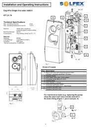
1. Appearance <strong>and</strong> structure of the unitSpecificationSpecificationUnit Model <strong>ESP</strong> <strong>Classic</strong> <strong>15kW</strong> <strong>17kW</strong> <strong>25kW</strong>Cooling capacity<strong>Heat</strong>ing capacitykW 11.0 13.0 22.0BTU/h 40000 45000 75000kW 14.0 16.0 24.0BTU/h 48000 55000 82000Cooling power input kW 4.0 4.6 6.9<strong>Heat</strong>ing power input kW 4.2 4.9 7.4Running current (Cooling/<strong>Heat</strong>ing) A 17.4/18.3 20.0/21.3 30.0/32.2Power supply V/Ph/Hz 230/1/50 230/1/50 230/1/50Compressor quantity 2 2 3Compressor Rotary Rotary Rotary2. The data of unitFan quantity 2 2 2Fan power input W 120 x 2 120 x 20 200 x 2Fan rotate speed RPM 850 850 750Noise dB(A) 56 56 59Water pump input kW 0.2 0.2 0.75Water head m 10 10 24Water connection inch 1 1 1.5Water flow volume m²/h 2.3 2.8 3.8Water pressure drop kPa 34 34 36Unit net dimensions mm See the drawing of the unitsUnit shipping dimensions (L/W/H) mm See package labelNet weight kg See nameplateShipping weight kg See package label5Cooling: Ambient temperature: 35°C/24°C, Inlet/outlet water temperature: 12°C/7°C<strong>Heat</strong>ing: Ambient Temperature: 7°C/6°C, Inlet/outlet water temperature: 40°C/45°C(Above information just for your reference only. Please subject to nameplate on the unit)PLEASE NOTE: Tested under EN14511 test conditions the units heating outputis <strong>15kW</strong>, <strong>17kW</strong> <strong>and</strong> <strong>25kW</strong> respective ly with correspondingly higher COPs.©<strong>ESP</strong> Oct2009
Specification<strong>Installation</strong>3. Unit Dimension1 Application of heat pump1.1 Only for air-con1.2 Air-con <strong>and</strong> super heater (for hot water)6
<strong>Installation</strong>2. Choose a right heat pump unit2.0 Choosing the right sized heat pump is critical to the efficiency of the system – if it is toosmall, it may cause the heat pump to operate outside its design cases <strong>and</strong>, if too large, theunit will cycle too often. If you have any doubt about the size of you unit, please consultyour system designer before installing the unit.2.1 Based on the local climatic conditions, construction methodology, size of property, insulationlevel (floor, walls, roof <strong>and</strong> windows), your system designer should have calculated the requiredheating capacity per square meter.2.2 Based upon your heating requirement per square meter, you can calculate the size of theASHP required to heat the desired “<strong>Heat</strong>ing Envelope” (the areas within your house that is tobe heated by your system).2.3 Air source heat pumps (“ASHP”) are suitable for domestic <strong>and</strong> commercial buildings.3. <strong>Installation</strong> place The unit can be installed on any level <strong>and</strong> stable site outside. If you do not have a level/stablesite that the ASHP can be fixed to, you can prepare a concrete plinth to site the unit on –make sure that you make the plinth about 10cm larger than the ASHP dimensions so thatlocating the unit is easy. As the units are heavy, it is best not to have to move the unitaround to small measuring tolerances.Further installation/location considerations are as follows: The location must be well ventilated. The unit must not be exposed to flames or very hot radiated temperatures (e.g. Bonfires in thegarden). The unit must be kept clear of deep settled snow <strong>and</strong> ice around it. The plinth that the ASHPsits on should be raised 150mm from general ground level to keep the unit above snowfall.If snow is higher than the plinth, you need to clear snow around the unit. There must not be any obstacles near the air inlet <strong>and</strong> outlet of the heat pump – obstacles willdisrupt air flow to <strong>and</strong> from the unit <strong>and</strong> this can have an adverse impact upon efficiency. The installation site should be sheltered from direct high winds as this can adversely impactupon the performance of the unit. You should make provision for full <strong>and</strong> appropriate drainage of condensate water produced bythe unit <strong>and</strong> be sure to not drain the condensate to surfaces that could freeze over <strong>and</strong> be ahazard. There must be adequate space around the unit for maintenance.<strong>Installation</strong>4. <strong>Installation</strong> methodThe heat pump should be fixed to the base such that it is level. Rubber anti-vibration pads aresupplied with most ASHP units <strong>and</strong> can be purchased from the supplier as an extra in all othercases.5. Water loop connectionPlease NOTE the following: Install all pipe work in a manner that minimizes resistance/back pressure – otherwise theflow switch may trigger <strong>and</strong> shut down the unit. Make sure that all system pipe work is clear of obstructions or blockage. The water leakpressure test must be carried out to ensure there is no water leaking – the leak test shouldbe carried out before the heat pimp is connected in to the system. Once the leak test hasbeen successfully completed, insulation may be installed on all exposed pipe work. Where not fitted with a pressurization vessel as st<strong>and</strong>ard, an ancillary pressure vessel shouldbe fitted to the un-vented loop. The expansion vessel should be installed in accordancewith local/national Regulations or recommendations made by suitably qualified Authorities. The pressurised heating loop will need to be purged of air <strong>and</strong> it is critical that all air is expelledfrom the system – otherwise, the intelligent controller may prevent the systemoperating in order to protect key components. To assist in this process, auto air ventsshould be fitted in the loop at the highest points or “dead legs” within the system. Air inthe system will show as system error Code 003. A thermometer <strong>and</strong> pressure meter must be fitted as close as reasonably possible at the waterinlet <strong>and</strong> outlet of the unit for easy inspection during operation.6. Power supply connection Open the front panel <strong>and</strong> open the power supply access. The power supply must go through the supply wire access point <strong>and</strong> be connected to thepower supply terminals provided within the unit. Then connect the controller block/clipconnector signal wires of the remote controller to the main controller. If an external water pump is needed, please insert the power supply wire for the externalwater pump into the unit via the same wire access <strong>and</strong> connect to the water pump terminalson the Chiller 300 Control inside the unit.7©<strong>ESP</strong> Oct2009
<strong>Installation</strong> If an auxiliary heater is required <strong>and</strong> it is to be controlled by the heat pump controller, therelay (or power) of the auxiliary heater must be connected a to the relevant output of thecontroller.NOTE – The unit needs to be wired back to the consumer unit via a 32 A, type C MCB. Pleaseensure that all electrical work is carried out by a suitably qualified electrician.7. Location of the unit<strong>Installation</strong>9. Trial runningInspection before trial running: Check <strong>and</strong> make sure that the pipe connections are right <strong>and</strong> the relevant valves are open. Check the water loop, to ensure that the water inside of the expansion vessel is adequate,the water supply is good <strong>and</strong> that the water loop is full of water <strong>and</strong> without any air in it.Also make sure there is suitable <strong>and</strong> adequate insulation for the water pipes. Check the electrical wiring again to make sure that all wires are securely in place <strong>and</strong> connectedwhere they should be. Make sure that the wiring has been installed in line with thediagram provided <strong>and</strong> that the earthing is properly connected. Check the heat pump unit over thoroughly, including all of the screws <strong>and</strong> parts of the heatpump to see if they are in good order, secure <strong>and</strong> suitable to be commissioned. When thepower is switched on, review the unit status noted on the remote controller to see if thereis any error message showing. [The gas gauge can be connected to the check valve to seethe high pressure (or low pressure) of the system during trial running.Trial running8. TransitWhen the unit need to be hung up during installation, a 8meters cable is needed, <strong>and</strong> there must be soft materialbetween the cable <strong>and</strong> the unit to prevent damage tothe heat pump cabinet. (See picture 1)Pic 1 Start the heat pump by pressing " or " key on the remote controller. Check whetherthe water pump is running - if it runs normally there will be 0.2 MPa on the water pressuremeter. When the water pump has been running for 1 minute, the compressor will start. Listen tomake sure that on start up the compressor(s) do not make any unusual sounds. If you hearanything abnormal please stop the unit <strong>and</strong> check the compressor for any obvious problems.If the compressor runs well check the pressure meter of the refrigerant. Then check whether the power input <strong>and</strong> running current is in line with this manual. If notplease stop <strong>and</strong> check over the installation work again. Adjust the valves on the water loop, to makes sure that the hot water supply to each dooris good <strong>and</strong> meet the requirement of heating (or cooling). Check that the outlet water temperature is stable. Please note that running parameters are factory set <strong>and</strong> may not be altered by the end user– parameter settings must be locked.8©<strong>ESP</strong> Oct2009
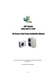
UsageUsage1) Wire controller functions instruction2) How to use the remote controller:r9©<strong>ESP</strong> Oct2009
UsageUsage10
UsageUsage11
MaintenanceMaintenance Check the water supply <strong>and</strong> air vent once a quarter to prevent there being inadequate water availableor not enough air circulating around the Unit.Clean the inline water filter as required as is sensible based upon your water supply. The above inimportant as a lack of water <strong>and</strong>/or dirty water in the system can damage the unit.The heat pump will start run the water pump once every 72 hours when it is not in regular use.This is to try <strong>and</strong> avoid freezing the system. Keep the unit in a place which is dry <strong>and</strong> clean <strong>and</strong> has good ventilation all round – the front <strong>and</strong>back of the unit are of particular importance.You should also clean the evaporator to the rear <strong>and</strong> side of the unit every in 1 or 2 month(depending on the time of year – leaves can affect performance) in order to keep the maximumheat exchange surface. During maintenance, check each part of the unit <strong>and</strong> the pressure of the system (water side <strong>and</strong>refrigerant). Replace parts as necessary <strong>and</strong> recharge the refrigerant if needed. Check the power supply <strong>and</strong> the electrical system - make sure that the electrical components arefree <strong>and</strong> clear of any foreign matter <strong>and</strong> check that wiring appears intact <strong>and</strong> free of any problems. If the heat pump is not in use for a long period, please drain out all the water in the unit <strong>and</strong> sealthe unit to keep t good. Please drain the water from the lowest point of the heat exchanger toavoid freezing in winter. Water recharge <strong>and</strong> inspection of the heat pump is needed before it isrestarted. Please drain out the water in the super heater of the heat pump unit in winter, when the superheater is not used. The water loop of the heat pump MUST be protected from freezing in late Autumn/winter/earlySpring . Please note the recommendations below - If not followed the warranty for the heat pumpwill be invalidated.(1) Please do not shut off the power supply to the heat pump in Winter. When the ambienttemperature outside is below 0°C <strong>and</strong> if, the inlet water temperature is 2°C (or lower), theheat pump will run to provide heat to prevent frosting.(2) Use anti-freezing liquid (glycol/water mix 25/75)1) look for below table for the volume of the glycol water2) The glycol water can be added into the system via the expansion tank of the water loopor the filling loop.NOTE: If glycol water is too much, the water flow <strong>and</strong> water pump will be influenced <strong>and</strong> the heat exchangerate will be decreased. This table is for reference , please use anti-freezing water according to the real conditionof the local climate.2. Ordinary malfunction <strong>and</strong> solutionMalfunction Running lamp Reason ResolutionWater in 1 Flash The water inlet sensor is disengaged orshort circuitWater out 2 Flash The water outlet sensor is disengaged orshort circuitPipe temp. 1 3 Flash The pipe temp sensor is disengaged orshort circuitPipe temp. 2 4 Flash The pipe temp sensor is disengaged orshort circuitAmbient temp. 5 Flash The ambient temp sensor is disengaged orshort circuitTemp. difference ProtectFrost protectionFrost protectionWater flow volume not inadequate, waterpressure difference is too lowAmbient or inlet water temp. is too lowAmbient or inlet water temp. is too lowCheck or change the sensorCheck or change the sensorCheck or change the sensorCheck or change the sensorCheck or change the sensorCheck the water flow volume, or system obstructionSystem 1 System 1 protection was failed Check each protection point of system 1 removethe malfunction according to System ProtectionBoard malfunction tableSystem 2 System 2 protection was failed Check each protection point of system 2 removethe malfunction according to System ProtectionBoard malfunction tableWater flow 8 Flash No water/little water in water system Check the water flow volume or water pumpfailurePower phase (systemprotect)High/low pressureWrong electricity phase used or lack ofgood connectionGas charge too low or high. Possiblesystem blockageCheck connections of power cable <strong>and</strong> phase ofelectricity supplyCheck through each pressure switch <strong>and</strong> returncircuitTemp. difference error Water flow rate not high enough Check the water flow rate <strong>and</strong> identify whichcomponents has failed <strong>and</strong> replace accordingly12Communication problembetween unit <strong>and</strong> PCBController, unit <strong>and</strong> the PCBconnection failureCheck the connection
Maintenance(2) You can judge <strong>and</strong> remove the malfunctions according to the malfunction code display on thePROTECT 300 (only for 3 phase units).Maintenance(3) Look over <strong>and</strong> clear the failure according to below information.Failure Possible causes for the failure SolutionsDisplay Name Reason Action Recover(yes or no)Revolution<strong>Heat</strong> pump cannot bestarted1. Incorrect power supply2. Power supply cable loose3. Circuit breaker open/failed1. Shut off the power <strong>and</strong> check power supply2. Check power cable <strong>and</strong> re-make connection3. Check for cause <strong>and</strong> replace the fuse or circuit breaker1 Cooling water freezing Cooling water temp. toolow2 Cooling water anti freezingfailureCooling water temp. aftertube inlet too low3 Low pressure Low pressure switchaction4 Compressor exhaust temp toohighCompressor exhaust temptoo high5 Over-current on compressor Current through compressortoo high6 High pressure High pressure switchaction7 Temp. sensor before tubefailure8 Tube outlet temp. sensorfailureTemp. disengaged sensoror short circuitTemp. disengaged sensoror short circuit9 Exhaust temp. sensor failure Temp. disengaged sensoror short circuitUnit stops<strong>and</strong> alarmUnit stops<strong>and</strong> alarmUnit stops<strong>and</strong> alarmUnit stops<strong>and</strong> alarmUnit stops<strong>and</strong> alarmUnit stops<strong>and</strong> alarmUnit stops<strong>and</strong> alarmUnit stops<strong>and</strong> alarmUnit stops<strong>and</strong> alarmYesYesYesYesYesYesYesYesYesCheck water flow volume <strong>and</strong> tempsetting <strong>and</strong> controllerCheck the water systemCheck through the pressure switch<strong>and</strong> systemCheck through therefrigerant system for faults <strong>and</strong>overloadingCheck through the power supply tocompressor or for short circuitCheck through the pressure switch<strong>and</strong> systemCheck <strong>and</strong> renew the sensorCheck <strong>and</strong> renew the sensorCheck <strong>and</strong> renew the sensorNoisy water pump whenrunning or no watercirculating<strong>Heat</strong> pump capacity islow or compressorrunning continuouslyHigh temperature atcompressor exhaustLow pressure in refrigerantsystemCompressor not runningNoisy compressor1. Lack of water in the system2. Air in the system3. Water valves closed4. Dirt blocking the water filter1. Lack of refrigerant2. Inadequate insulation on water pipes3. Low heat exchange rate on air side exchanger4. Lack of water in the system1. Too much refrigerant2. Low heat exchange rate on air side exchanger1. Lack of refrigerant2. Block on filter or capillary1. Power supply failure2. Compressor contactor failed3. Power cable loose4. Automatic protection implemented on compressor5. Wrong setting on return water temp.6. Lack of water flow1. Refrigerant carry over to compressor2. Compressor failure1. Check the water supply <strong>and</strong> charge system fully2. Bleed the air from the system3. Open the valves4. Clean the water filter1. Check for refrigerant leakage <strong>and</strong> recharge the refrigerantafter repairing any leak2. Improve insulation on water pipes3. Clean the air side heat exchanger4. Clean the water filter1.Discharge the excess refrigerant2. Clean the air side heat exchanger1. Check for gas leakage <strong>and</strong> recharge refrigerant2. Replace filter or capillary1. Check the power supply to the compressor2. Replace compressor contactor3. Tighten the power cable4. Check the compressor exhaust temp.5. Reset the return water temp6. Clean the water filter <strong>and</strong> discharge any air in the system1.Evaporation rate low – check <strong>and</strong> repair as appropriate2. Install new compressorEPower supply wrongconnectionWrong connection or lackof connectionUnit stops<strong>and</strong> alarmYesCheck the connections <strong>and</strong> powersupply being used (i.e. single or 3phase)Fan not runningThe compressor runs butheat pump has no heatingor cooling capacity1. Failure of fan relay2. Fan motor broken1. No refrigerant in the heat pump2. <strong>Heat</strong> exchanger failure3. Compressor failure1. Replace the fan relay2. Replace fan motor1. Check system for leakage, repair as appropriate <strong>and</strong>recharge refrigerant2. Establish the cause of the failure <strong>and</strong> repair. Replace theheat exchanger3. Replace compressorLow outlet waterTemperature1. Low water flow rate2. Setting for water temp. too low.1. Clean the water filter <strong>and</strong> discharge any air in system2. Reset the desired water temperatureLow water flow protection1. Lack of water in the system2. Failure of flow switch1. Clean the water filter <strong>and</strong> discharge any air in the system2. Replace the flow switch13
AppendixAppendix 1<strong>Installation</strong> request1. The Manual covers only the units supplied by Earth Save Products Limited <strong>and</strong> not any othersystem components.2. Water pump is fitted inside the heat pump.3. Auto bleed vents must be is installed at the highest point(s) of the water system.4. The flow <strong>and</strong> return configuration should be installed in a manner that is suitable for any boiler –i.e. A “Y” water strainer must be fitted to the return pipe work with full isolation valves eitherside so that removing the filter for cleaning is a simple exercise – please note that failing to fit a“Y” strainer will invalidate the unit guarantee/warranty. Further, the system should be fitted witha Magnatec/boiler buddy scale inhibitor.You will also need to install a pressurization vessel <strong>and</strong> filling loop.AppendixThe way to install auxiliary heating in the system is as follows:1) <strong>Heat</strong> pump + auxiliary heating from a gas-fired boiler:2) <strong>Heat</strong> pump + auxiliary in-line electric boiler:Appendix 2NOT IN USEAppendix 3The heat pump unit is supplied with a blow off valve that will release pressure should the systemreach a pressure higher than 3 bar.Appendix 5Unit parameter settings:Please set unit running parameters according the following table:Appendix 4Fitting auxiliary heating to the heat pump system:The Unit allows for the addition of auxiliary heating in the system – this can be auxiliary electricalheating or gas boiler.14
AppendixAppendixPlease note:Connections explanation:Setting 00 relates to cooling mode only.Settings 01-08 relate to heating mode only. You can change these parameters according to yourpreference.Parameter Sub-Settings:Parameter 06 sub-settings:1: the unit has 1 compressor.2: the unit has 2 compressors.Parameter 07 sub-settings:0: the unit will restart automatically;1: the unit will not restart automatically.Appendix 7:Connections of PROTECT 300Parameter 08 sub-settings:0: Cooling mode only.1: <strong>Heat</strong> pump mode (heating <strong>and</strong> cooling, as required).2: Electrical auxiliary heating activated.3: <strong>Heat</strong>ing mode only.Parameter 09 sub-settings:For the <strong>ESP</strong> XK range, the parameter should be set as follows:1: 60 second delay before compressors start.30 second delay after compressors stop.Connections explanation:Appendix 6:Connections code of the main PCB15