MULTI-ROUTE UNIT M-66 - supersonic
MULTI-ROUTE UNIT M-66 - supersonic
MULTI-ROUTE UNIT M-66 - supersonic

Create successful ePaper yourself
Turn your PDF publications into a flip-book with our unique Google optimized e-Paper software.
MIX/HA<br />
SPLIT<br />
MIX/HA<br />
SPLIT<br />
MIX/HA<br />
SPLIT<br />
MIX/HA<br />
SPLIT<br />
POWER<br />
ON<br />
OFF<br />
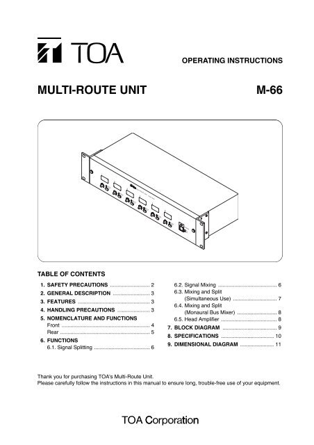
OPERATING INSTRUCTIONS<br />
<strong>MULTI</strong>-<strong>ROUTE</strong> <strong>UNIT</strong> M-<strong>66</strong><br />
1 2<br />
0 10<br />
MIX/HA<br />
SPLIT<br />
3<br />
<strong>MULTI</strong> <strong>ROUTE</strong> <strong>UNIT</strong> model M-<strong>66</strong><br />
0 10 0 10<br />
MIX/HA<br />
SPLIT<br />
4<br />
5 6<br />
0 10 0 10 0 10<br />
TABLE OF CONTENTS<br />
1. SAFETY PRECAUTIONS ........................... 2<br />
2. GENERAL DESCRIPTION ......................... 3<br />
3. FEATURES ................................................. 3<br />
4. HANDLING PRECAUTIONS ...................... 3<br />
5. NOMENCLATURE AND FUNCTIONS<br />
Front ............................................................ 4<br />
Rear ............................................................. 5<br />
6. FUNCTIONS<br />
6.1. Signal Splitting ...................................... 6<br />
6.2. Signal Mixing ........................................ 6<br />
6.3. Mixing and Split<br />
(Simultaneous Use) .............................. 7<br />
6.4. Mixing and Split<br />
(Monaural Bus Mixer) ........................... 8<br />
6.5. Head Amplifier ...................................... 8<br />
7. BLOCK DIAGRAM ..................................... 9<br />
8. SPECIFICATIONS .................................... 10<br />
9. DIMENSIONAL DIAGRAM ....................... 11<br />
Thank you for purchasing TOA's Multi-Route Unit.<br />
Please carefully follow the instructions in this manual to ensure long, trouble-free use of your equipment.
1. SAFETY PRECAUTIONS<br />
• Before installation or use, be sure to carefully read all the instructions in this section for correct and safe<br />
operation.<br />
• Be sure to follow all the precautionary instructions in this section, which contain important warnings and/or<br />
cautions regarding safety.<br />
• After reading, keep this manual handy for future reference.<br />
Safety Symbol and Message Conventions<br />
Safety symbols and messages described below are used in this manual to prevent bodily injury and property<br />
damage which could result from mishandling. Before operating your product, read this manual first and<br />
understand the safety symbols and messages so you are thoroughly aware of the potential safety hazards.<br />
WARNING<br />
CAUTION<br />
Indicates a potentially hazardous situation which, if mishandled, could<br />
result in death or serious personal injury.<br />
Indicates a potentially hazardous situation which, if mishandled, could<br />
result in moderate or minor personal injury, and/or property damage.<br />
2<br />
When Installing the Unit<br />
• Do not expose the unit to rain or an environment<br />
where it may be splashed by water or other liquids,<br />
as doing so may result in fire or electric shock.<br />
• Use the unit only with the voltage specified on the<br />
unit. Using a voltage higher than that which is<br />
specified may result in fire or electric shock.<br />
• Do not cut, kink, otherwise damage nor modify the<br />
power supply cord. In addition, avoid using the<br />
power cord in close proximity to heaters, and never<br />
place heavy objects -- including the unit itself -- on<br />
the power cord, as doing so may result in fire or<br />
electric shock.<br />
• Since the unit is designed for in-door use, do not<br />
install it outdoors. When it gets wet with rain, there<br />
is a danger of electric shock.<br />
• The apparatus shall be connected to a main socket<br />
outlet with a protective earthing connection.<br />
• The socket-outlet shall be installed near the<br />
equipment and the plug shall be easily accessible.<br />
When the Unit is in Use<br />
WARNING<br />
• Should the following irregularity be found during<br />
use, immediately switch off the power, disconnect<br />
the power supply plug from the AC outlet and<br />
contact your nearest TOA dealer. Make no further<br />
attempt to operate the unit in this condition as this<br />
may cause fire or electric shock.<br />
· If you detect smoke or a strange smell coming<br />
from the unit.<br />
· If water or any metallic object gets into the unit<br />
· If the unit falls, or the unit case breaks<br />
· If the power supply cord is damaged (exposure of<br />
the core, disconnection, etc.)<br />
· If it is malfunctioning (no tone sounds.)<br />
• To prevent a fire or electric shock, never open nor<br />
remove the unit case as there are high voltage<br />
components inside the unit. Refer all servicing to<br />
qualified service personnel.<br />
• Do not place cups, bowls, or other containers of<br />
liquid or metallic objects on top of the unit. If they<br />
accidentally spill into the unit, this may cause a fire<br />
or electric shock.<br />
• Do not insert nor drop metallic objects or<br />
flammable materials in the ventilation slots of the<br />
unit's cover, as this may result in fire or electric<br />
shock.<br />
• Do not touch a power supply plug during thunder<br />
and lightning, as this may result in electric shock.<br />
When Installing the Unit<br />
CAUTION<br />
• Never plug in nor remove the power supply plug<br />
with wet hands, as doing so may cause electric<br />
shock.<br />
• When unplugging the power supply cord, be sure<br />
to grasp the power supply plug; never pull on the<br />
cord itself. Operating the unit with a damaged<br />
power supply cord may cause a fire or electric<br />
shock.
• When moving the unit, be sure to remove its power<br />
supply cord from the wall outlet. Moving the unit<br />
with the power cord connected to the outlet may<br />
cause damage to the power cord, resulting in fire or<br />
electric shock. When removing the power cord, be<br />
sure to hold its plug to pull.<br />
• Avoid installing the unit in humid or dusty locations,<br />
in locations exposed to the direct sunlight, near the<br />
heaters, or in locations generating sooty smoke or<br />
steam as doing otherwise may result in fire or<br />
electric shock.<br />
• Be sure to follow the instructions below when rackmounting<br />
the unit. Failure to do so may cause a fire<br />
or personal injury.<br />
· Install the equipment rack on a stable, hard floor.<br />
Fix it with anchor bolts or take other arrangements<br />
to prevent it from falling down.<br />
· When connecting the unit's power cord to an AC<br />
outlet, use the AC outlet with current capacity<br />
allowable to the unit.<br />
· The supplied rack-mounting screws can be used<br />
for the TOA equipment rack only. Do not use<br />
them for other racks.<br />
When the Unit is in Use<br />
• If dust accumulates on the power supply plug or in<br />
the wall AC outlet, a fire may result. Clean it<br />
periodically. In addition, insert the plug in the wall<br />
outlet securely.<br />
• Switch off the power, and unplug the power supply<br />
plug from the AC outlet for safety purposes when<br />
cleaning or leaving the unit unused for 10 days or<br />
more. Doing otherwise may cause a fire or electric<br />
shock.<br />
The lighting flash with arrowhead symbol, within an equilateral triangle, is intended to alert the user<br />
to the presence of uninsulated "dangerous voltage" within the product's enclosure that may be of<br />
sufficient magnitude to constitute a risk of electric shock to persons.<br />
The exclamation point within an equilateral triangle is intended to alert the user to the presence of<br />
important operation and maintenance (servicing) instruction in the literature accompanying the<br />
appliance.<br />
2. GENERAL DESCRIPTION<br />
TOA's M-<strong>66</strong> Multi-Route Unit functions as a splitter, a mixer, or a microphone head amplifier featuring 6 inputs<br />
and 6 outputs. Because functions can be selected individually for each channel, a wide range of signal routing<br />
configurations can be achieved. The M-<strong>66</strong> can be mounted in an EIA Standard equipment rack (2-unit size).<br />
3. FEATURES<br />
• Inputs 1 through 6 are compatible with a wide range of signal levels from microphone to line levels.<br />
• The function of each channel can be easily set using the mode switches mounted on the front panel. Setting<br />
can also be easily checked.<br />
• A bridge output terminal and a mixing input terminal are also provided. When using the M-<strong>66</strong> as a splitter or<br />
mixer, channels can easily be expanded with the addition of other M-<strong>66</strong> units.<br />
• Inputs and outputs are all electrically balanced. (#1: Ground, #2: Hot, #3: Cold)<br />
• Built-in security cover prevents accidental setting changes.<br />
4. HANDLING PRECAUTIONS<br />
• Line voltage must not exceed ±10% of that indicated at the unit's AC inlet. Line frequency can be 50 Hz or<br />
60 Hz.<br />
• The operating temperature range is between 0 and 40°C with less than 90% humidity (and no<br />
condensation).<br />
• To clean, wipe down with a soft, dry cloth. Never use a chemically-treated cleaning cloth or volatile liquids,<br />
such as benzine and thinner, because the unit's parts may be deformed or its finish discolored.<br />
3
5. NOMENCLATURE AND FUNCTIONS<br />
[Front]<br />
6<br />
5<br />
<strong>MULTI</strong> <strong>ROUTE</strong> <strong>UNIT</strong> model M-<strong>66</strong><br />
1 2<br />
3<br />
4<br />
5 6<br />
POWER<br />
MIX/HA<br />
SPLIT<br />
MIX/HA<br />
SPLIT<br />
MIX/HA<br />
SPLIT<br />
MIX/HA<br />
SPLIT<br />
MIX/HA<br />
SPLIT<br />
MIX/HA<br />
SPLIT<br />
ON<br />
OFF<br />
0 10<br />
0 10 0 10<br />
0 10 0 10 0 10<br />
4<br />
3<br />
2<br />
1<br />
1. Power switch [ ON, OFF]<br />
Power is switched on and off with each<br />
depression of this switch.<br />
2. Power lamp [POWER]<br />
Lights when the power is switched on.<br />
3. Mode switch [ MIX/HA, SPLIT]<br />
MIX/HA: The channel functions as a mixer<br />
and a head amplifier.<br />
SPLIT: A signal to the SPLIT IN terminal is<br />
distributed to the corresponding<br />
outputs.<br />
5. Name label<br />
Write the name of each input and output in this<br />
label.<br />
6. Security cover<br />
Attach this cover after completing all settings to<br />
prevent accidental setting changes. Push in both<br />
the left and right knobs to attach the cover, and<br />
pull those knobs to detach.<br />
4. Volume control<br />
Adjusts the volume of each channel.<br />
• Mixer/head amplifier mode<br />
(Mode switch position: MIX/HA)<br />
Adjusts the volume of each input signal, which<br />
goes to the mixing bus (for use as a mixer) and<br />
also directly goes to the output of the same input<br />
channel (for use as a head amplifier).<br />
• Splitter mode<br />
(Mode switch position: SPLIT)<br />
Adjusts each output volume.<br />
4
[Rear]<br />
17<br />
15<br />
7 8 9<br />
SIGNAL<br />
GND<br />
BRIDGE<br />
SPLIT IN [-10 dB]<br />
PAD<br />
INPUTS [-60/-10 dB]<br />
6<br />
5<br />
4<br />
3<br />
2<br />
PAD M/L PAD M/L PAD M/L PAD M/L PAD M/L<br />
1<br />
PAD M/L<br />
<strong>MULTI</strong> <strong>ROUTE</strong> <strong>UNIT</strong><br />
model M-<strong>66</strong><br />
TOA Corporation<br />
MADE IN JAPAN<br />
6<br />
5<br />
OUTPUTS [+4 dB]<br />
4<br />
3<br />
2<br />
1<br />
MIX OUT<br />
[+4 dB]<br />
MIX IN<br />
[+4 dB]<br />
IN<br />
OUT<br />
LINE<br />
MIC<br />
XLR TYPE<br />
1: GND<br />
2: HOT<br />
3: COLD<br />
16<br />
11 10<br />
12 14 13<br />
7. Input terminal (XLR-3-31 or equivalent)<br />
[INPUTS 1 – 6]<br />
This electrically-balanced terminal receives the<br />
signal to be used for mixer/head amplifier<br />
applications. Use the XLR-3-12C connector or its<br />
equivalent for connection.<br />
8. Pad switch [PAD]<br />
IN: Select this position when an input level<br />
is too high to correct the sound<br />
distortion with the volume control. This<br />
switch attenuates the level by 20 dB.<br />
OUT: Select this position for normal use.<br />
Tip<br />
Input level can be selected from – 60, – 40, –10,<br />
and +10 dB, by using the pad switch in<br />
combination with the input sensitivity selector<br />
switch.<br />
9. Input sensitivity selector switch [M/L]<br />
LINE: Select this position when connecting a<br />
wireless tuner or line signal level<br />
equipment. Input sensitivity is –10 dB.<br />
MIC: Use this position when connecting a<br />
microphone. Input sensitivity is – 60 dB.<br />
10. Split input terminal (XLR-3-31 or equivalent)<br />
[SPLIT IN]<br />
This electrically-balanced terminal receives a line<br />
level signal to be distributed. Use the XLR-3-12C<br />
connector or its equivalent for connection.<br />
11. Bridge output terminal<br />
(XLR-3-32 or equivalent) [BRIDGE]<br />
Used to connect other M-<strong>66</strong> units to increase the<br />
number of split outputs. This bridge output<br />
terminal is for the split input terminal. Use the<br />
XLR-3-11C connector or its equivalent for<br />
connection.<br />
12. Output terminal (XLR-3-32 or equivalent)<br />
[OUTPUTS 1 – 6]<br />
This electrically-balanced terminal outputs the<br />
signal in mode set with the mode switch (3).<br />
Use the XLR-3-11C connector or its equivalent<br />
for connection.<br />
• Mixer/head amplifier mode<br />
(Mode switch position: MIX/HA)<br />
The signal to the input goes to its corresponding<br />
output when the channel is used as a head<br />
amplifier.<br />
• Splitter mode<br />
(Mode switch position: SPLIT)<br />
The signal to be distributed from the split input<br />
terminal is output.<br />
13. Mixing input terminal<br />
(XLR-3-31 or equivalent) [MIX IN]<br />
This electrically-balanced terminal is an input<br />
terminal to the unit's mixing bus. By connecting<br />
this terminal to other M-<strong>66</strong>'s mixing output or<br />
other mixer, the number of mixing channels can<br />
be increased. Use the XLR-3-12C connector or<br />
its equivalent for connection.<br />
14. Mixing output terminal<br />
(XLR-3-32 or equivalent) [MIX OUT]<br />
This electrically-balanced terminal outputs the<br />
mixed signal of each channel input and mixing<br />
input. Use the XLR-3-11C connector or its<br />
equivalent for connection.<br />
15. Fuse holder<br />
When the fuse has blown off, remove the cause<br />
and replace it with the fuse of the rating indicated<br />
on the unit.<br />
16. AC inlet<br />
Using the supplied power cord, connect this inlet<br />
to a wall outlet.<br />
17. Grounding terminal [SIGNAL GND]<br />
Ground this terminal.<br />
5
6. FUNCTIONS<br />
6.1. Signal Splitting<br />
6.1.1. Single input/6 outputs<br />
Input<br />
The volume of outputs 1-6 is adjustable.<br />
SIGNAL<br />
GND<br />
BRIDGE SPLIT IN [-10 dB]<br />
6<br />
5<br />
INPUTS [-60/-10 dB]<br />
4<br />
3<br />
2<br />
1<br />
PAD<br />
PAD M/L PAD M/L PAD M/L PAD M/L PAD M/L<br />
PAD M/L<br />
[Mode switch setting]<br />
Set the switch of each channel (1-6) to [SPLIT]<br />
position.<br />
<strong>MULTI</strong> <strong>ROUTE</strong> <strong>UNIT</strong><br />
model M-<strong>66</strong><br />
TOA Corporation<br />
MADE IN JAPAN<br />
6<br />
5<br />
OUTPUTS [+4 dB]<br />
4<br />
3<br />
2<br />
1<br />
MIX OUT<br />
[+4 dB]<br />
MIX IN<br />
[+4 dB]<br />
IN<br />
OUT<br />
LINE<br />
MIC<br />
XLR TYPE<br />
1: GND<br />
2: HOT<br />
3: COLD<br />
Split output<br />
6.1.2. Single input/12 outputs<br />
Output can be expanded by connecting 2 M-<strong>66</strong> units.<br />
It is also possible to adjust the volume of outputs 1-6<br />
of both units.<br />
[Mode switch setting]<br />
Set the switch of each channel (1-6) of both units to<br />
[SPLIT] position.<br />
SIGNAL<br />
GND<br />
<strong>MULTI</strong> <strong>ROUTE</strong> <strong>UNIT</strong><br />
model M-<strong>66</strong><br />
TOA Corporation<br />
MADE IN JAPAN<br />
BRIDGE<br />
Bridge output<br />
terminal<br />
Split input<br />
terminal<br />
Input<br />
SPLIT IN [-10 dB]<br />
PAD<br />
6<br />
6<br />
5<br />
5<br />
4<br />
4<br />
PAD M/L PAD M/L PAD M/L PAD M/L PAD M/L<br />
OUTPUTS [+4 dB]<br />
INPUTS [-60/-10 dB]<br />
Split output<br />
3<br />
3<br />
2<br />
1<br />
2<br />
MIX OUT<br />
[+4 dB]<br />
MIX IN<br />
[+4 dB]<br />
1<br />
PAD M/L<br />
IN<br />
OUT<br />
LINE<br />
MIC<br />
XLR TYPE<br />
1: GND<br />
2: HOT<br />
3: COLD<br />
SIGNAL<br />
GND<br />
BRIDGE<br />
SPLIT IN [-10 dB]<br />
6<br />
5<br />
INPUTS [-60/-10 dB]<br />
4<br />
3<br />
2<br />
1<br />
PAD<br />
PAD M/L PAD M/L PAD M/L PAD M/L PAD M/L<br />
PAD M/L<br />
<strong>MULTI</strong> <strong>ROUTE</strong> <strong>UNIT</strong><br />
model M-<strong>66</strong><br />
TOA Corporation<br />
MADE IN JAPAN<br />
6<br />
5<br />
OUTPUTS [+4 dB]<br />
4<br />
3<br />
2<br />
1<br />
MIX OUT<br />
[+4 dB]<br />
MIX IN<br />
[+4 dB]<br />
IN<br />
OUT<br />
LINE<br />
MIC<br />
XLR TYPE<br />
1: GND<br />
2: HOT<br />
3: COLD<br />
6.2. Signal Mixing<br />
6.2.1. 6 inputs/single output<br />
Split output<br />
Input<br />
The volume of inputs 1-6 is adjustable.<br />
[Mode switch setting]<br />
Set the switch of each channel (1-6) to [MIX/HA]<br />
position.<br />
SIGNAL<br />
GND<br />
<strong>MULTI</strong> <strong>ROUTE</strong> <strong>UNIT</strong><br />
model M-<strong>66</strong><br />
TOA Corporation<br />
MADE IN JAPAN<br />
BRIDGE<br />
SPLIT IN [-10 dB]<br />
PAD<br />
6<br />
6<br />
5<br />
5<br />
4<br />
4<br />
PAD M/L PAD M/L PAD M/L PAD M/L PAD M/L<br />
OUTPUTS [+4 dB]<br />
INPUTS [-60/-10 dB]<br />
3<br />
3<br />
2<br />
1<br />
2<br />
MIX OUT<br />
[+4 dB]<br />
MIX IN<br />
[+4 dB]<br />
1<br />
PAD M/L<br />
IN<br />
OUT<br />
LINE<br />
MIC<br />
XLR TYPE<br />
1: GND<br />
2: HOT<br />
3: COLD<br />
Mixing output<br />
6.2.2. 12 inputs/single output<br />
Input<br />
Input can be expanded by connecting 2 M-<strong>66</strong> units. It<br />
is also possible to adjust the volume of inputs 1-6 of<br />
both units.<br />
[Mode switch setting]<br />
Set the switch of each channel (1-6) of both units to<br />
[MIX/HA] position.<br />
SIGNAL<br />
GND<br />
<strong>MULTI</strong> <strong>ROUTE</strong> <strong>UNIT</strong><br />
model M-<strong>66</strong><br />
TOA Corporation<br />
MADE IN JAPAN<br />
BRIDGE<br />
SPLIT IN [-10 dB]<br />
PAD<br />
6<br />
6<br />
5<br />
5<br />
4<br />
4<br />
PAD M/L PAD M/L PAD M/L PAD M/L PAD M/L<br />
OUTPUTS [+4 dB]<br />
INPUTS [-60/-10 dB]<br />
3<br />
Input<br />
3<br />
2<br />
1<br />
2<br />
MIX OUT<br />
[+4 dB]<br />
MIX IN<br />
[+4 dB]<br />
1<br />
PAD M/L<br />
IN<br />
OUT<br />
LINE<br />
MIC<br />
XLR TYPE<br />
1: GND<br />
2: HOT<br />
3: COLD<br />
Mixing output<br />
terminal<br />
SIGNAL<br />
GND<br />
BRIDGE<br />
SPLIT IN [-10 dB]<br />
6<br />
5<br />
INPUTS [-60/-10 dB]<br />
4<br />
3<br />
2<br />
1<br />
PAD<br />
PAD M/L PAD M/L PAD M/L PAD M/L PAD M/L<br />
PAD M/L<br />
<strong>MULTI</strong> <strong>ROUTE</strong> <strong>UNIT</strong><br />
model M-<strong>66</strong><br />
TOA Corporation<br />
MADE IN JAPAN<br />
6<br />
5<br />
OUTPUTS [+4 dB]<br />
4<br />
3<br />
2<br />
1<br />
MIX OUT<br />
[+4 dB]<br />
MIX IN<br />
[+4 dB]<br />
IN<br />
OUT<br />
LINE<br />
MIC<br />
XLR TYPE<br />
1: GND<br />
2: HOT<br />
3: COLD<br />
Mixing input<br />
terminal<br />
Mixing output<br />
6
6.3. Mixing and Split (Simultaneous Use)<br />
6.3.1. 2 inputs mixing and 4 split outputs<br />
It is possible to adjust the volume of inputs 1 and 2,<br />
and that of outputs 3-6.<br />
SIGNAL<br />
GND<br />
Input<br />
BRIDGE SPLIT IN [-10 dB]<br />
PAD<br />
Input<br />
INPUTS [-60/-10 dB]<br />
6<br />
5<br />
4<br />
3<br />
2<br />
PAD M/L PAD M/L PAD M/L PAD M/L PAD M/L<br />
1<br />
PAD M/L<br />
[Mode switch setting]<br />
Set the switches of channels 1 and 2 to [MIX/HA]<br />
position, and those of channels 3-6 to [SPLIT]<br />
position.<br />
<strong>MULTI</strong> <strong>ROUTE</strong> <strong>UNIT</strong><br />
model M-<strong>66</strong><br />
TOA Corporation<br />
MADE IN JAPAN<br />
OUTPUTS [+4 dB]<br />
6<br />
5<br />
4<br />
3<br />
Split output<br />
2<br />
1<br />
MIX OUT<br />
[+4 dB]<br />
MIX IN<br />
[+4 dB]<br />
IN<br />
OUT<br />
LINE<br />
MIC<br />
XLR TYPE<br />
1: GND<br />
2: HOT<br />
3: COLD<br />
Mixing output<br />
6.3.2. 3 inputs mixing and 3 split outputs<br />
It is possible to adjust the volume of inputs 1-3, and<br />
that of outputs 4-6.<br />
SIGNAL<br />
GND<br />
Input<br />
BRIDGE SPLIT IN [-10 dB]<br />
PAD<br />
Input<br />
INPUTS [-60/-10 dB]<br />
6<br />
5<br />
4<br />
3<br />
2<br />
PAD M/L PAD M/L PAD M/L PAD M/L PAD M/L<br />
1<br />
PAD M/L<br />
[Mode switch setting]<br />
Set the switches of channels 1-3 to [MIX/HA]<br />
position, and those of channels 4-6 to [SPLIT]<br />
position.<br />
<strong>MULTI</strong> <strong>ROUTE</strong> <strong>UNIT</strong><br />
model M-<strong>66</strong><br />
TOA Corporation<br />
MADE IN JAPAN<br />
OUTPUTS [+4 dB]<br />
6<br />
5<br />
4<br />
3<br />
Split output<br />
2<br />
1<br />
MIX OUT<br />
[+4 dB]<br />
MIX IN<br />
[+4 dB]<br />
IN<br />
OUT<br />
LINE<br />
MIC<br />
XLR TYPE<br />
1: GND<br />
2: HOT<br />
3: COLD<br />
Mixing output<br />
6.3.3. 4 inputs mixing and 2 split outputs<br />
It is possible to adjust the volume of inputs 1-4, and<br />
that of outputs 5 and 6.<br />
SIGNAL<br />
GND<br />
Input<br />
BRIDGE SPLIT IN [-10 dB]<br />
PAD<br />
Input<br />
INPUTS [-60/-10 dB]<br />
6<br />
5<br />
4<br />
3<br />
2<br />
PAD M/L PAD M/L PAD M/L PAD M/L PAD M/L<br />
1<br />
PAD M/L<br />
[Mode switch setting]<br />
Set the switches of channels 1-4 to [MIX/HA]<br />
position, and those of channels 5 and 6 to [SPLIT]<br />
position.<br />
<strong>MULTI</strong> <strong>ROUTE</strong> <strong>UNIT</strong><br />
model M-<strong>66</strong><br />
TOA Corporation<br />
MADE IN JAPAN<br />
OUTPUTS [+4 dB]<br />
6<br />
5<br />
4<br />
3<br />
Split output<br />
2<br />
1<br />
MIX OUT<br />
[+4 dB]<br />
MIX IN<br />
[+4 dB]<br />
IN<br />
OUT<br />
LINE<br />
MIC<br />
XLR TYPE<br />
1: GND<br />
2: HOT<br />
3: COLD<br />
Mixing output<br />
7
6.4. Mixing and Split (Monaural Bus Mixer)<br />
By connecting the mixing output terminal to the split input terminal, signals mixed together can be distributed<br />
to multiple split outputs.<br />
6.4.1. 2 inputs/4 outputs<br />
Input<br />
It is possible to adjust the volume of inputs 1 and 2,<br />
and that of outputs 3-6.<br />
Split input terminal<br />
[Mode switch setting]<br />
Set the switches of channels 1 and 2 to [MIX/HA]<br />
position, and those of channels 3-6 to [SPLIT]<br />
position.<br />
SIGNAL<br />
GND<br />
<strong>MULTI</strong> <strong>ROUTE</strong> <strong>UNIT</strong><br />
model M-<strong>66</strong><br />
TOA Corporation<br />
MADE IN JAPAN<br />
BRIDGE<br />
SPLIT IN [-10 dB]<br />
PAD<br />
6<br />
6<br />
5<br />
5<br />
4<br />
4<br />
PAD M/L PAD M/L PAD M/L PAD M/L PAD M/L<br />
OUTPUTS [+4 dB]<br />
Split output<br />
INPUTS [-60/-10 dB]<br />
3<br />
3<br />
2<br />
1<br />
2<br />
MIX OUT<br />
[+4 dB]<br />
MIX IN<br />
[+4 dB]<br />
1<br />
PAD M/L<br />
IN<br />
OUT<br />
LINE<br />
MIC<br />
XLR TYPE<br />
1: GND<br />
2: HOT<br />
3: COLD<br />
Mixing output<br />
terminal<br />
6.4.2. 3 inputs/3 outputs<br />
Input<br />
It is possible to adjust the volume of inputs 1-3, and<br />
that of outputs 4-6.<br />
Split input terminal<br />
[Mode switch setting]<br />
Set the switches of channels 1-3 to [MIX/HA]<br />
position, and those of channels 4-6 to [SPLIT]<br />
position.<br />
SIGNAL<br />
GND<br />
<strong>MULTI</strong> <strong>ROUTE</strong> <strong>UNIT</strong><br />
model M-<strong>66</strong><br />
TOA Corporation<br />
MADE IN JAPAN<br />
BRIDGE<br />
SPLIT IN [-10 dB]<br />
PAD<br />
6<br />
6<br />
5<br />
5<br />
4<br />
4<br />
PAD M/L PAD M/L PAD M/L PAD M/L PAD M/L<br />
OUTPUTS [+4 dB]<br />
Split output<br />
INPUTS [-60/-10 dB]<br />
3<br />
3<br />
2<br />
1<br />
2<br />
MIX OUT<br />
[+4 dB]<br />
MIX IN<br />
[+4 dB]<br />
1<br />
PAD M/L<br />
IN<br />
OUT<br />
LINE<br />
MIC<br />
XLR TYPE<br />
1: GND<br />
2: HOT<br />
3: COLD<br />
Mixing output<br />
terminal<br />
6.4.3. 4 inputs/2 outputs<br />
Input<br />
It is possible to adjust the volume of inputs 1-4, and<br />
that of outputs 5 and 6.<br />
Split input terminal<br />
[Mode switch setting]<br />
Set the switches of channels 1-4 to [MIX/HA]<br />
position, and those of channels 5 and 6 to [SPLIT]<br />
position.<br />
SIGNAL<br />
GND<br />
<strong>MULTI</strong> <strong>ROUTE</strong> <strong>UNIT</strong><br />
model M-<strong>66</strong><br />
TOA Corporation<br />
MADE IN JAPAN<br />
BRIDGE<br />
SPLIT IN [-10 dB]<br />
PAD<br />
6<br />
6<br />
5<br />
5<br />
4<br />
4<br />
PAD M/L PAD M/L PAD M/L PAD M/L PAD M/L<br />
Split output<br />
OUTPUTS [+4 dB]<br />
INPUTS [-60/-10 dB]<br />
3<br />
3<br />
2<br />
1<br />
2<br />
MIX OUT<br />
[+4 dB]<br />
MIX IN<br />
[+4 dB]<br />
1<br />
PAD M/L<br />
IN<br />
OUT<br />
LINE<br />
MIC<br />
XLR TYPE<br />
1: GND<br />
2: HOT<br />
3: COLD<br />
Mixing output<br />
terminal<br />
6.5. Head Amplifier<br />
Input<br />
It is possible to adjust the volume of inputs 1-6.<br />
[Mode switch setting]<br />
Set the switches of channels 1-6 to [MIX/HA]<br />
position.<br />
SIGNAL<br />
GND<br />
<strong>MULTI</strong> <strong>ROUTE</strong> <strong>UNIT</strong><br />
model M-<strong>66</strong><br />
TOA Corporation<br />
MADE IN JAPAN<br />
BRIDGE<br />
SPLIT IN [-10 dB]<br />
PAD<br />
6<br />
6<br />
5<br />
5<br />
4<br />
4<br />
PAD M/L PAD M/L PAD M/L PAD M/L PAD M/L<br />
OUTPUTS [+4 dB]<br />
INPUTS [-60/-10 dB]<br />
3<br />
3<br />
2<br />
1<br />
2<br />
MIX OUT<br />
[+4 dB]<br />
MIX IN<br />
[+4 dB]<br />
1<br />
PAD M/L<br />
IN<br />
OUT<br />
LINE<br />
MIC<br />
XLR TYPE<br />
1: GND<br />
2: HOT<br />
3: COLD<br />
Output<br />
8
7. BLOCK DIAGRAM<br />
INPUT 1<br />
-60/-10dB<br />
PAD<br />
20dB<br />
HA<br />
MIX/HA<br />
SPLIT<br />
BA<br />
EBA<br />
<br />
OUTPUT 1<br />
+4dB<br />
INPUT 2<br />
-60/-10dB<br />
IN/OUT<br />
PAD<br />
20dB<br />
MIC/LINE<br />
<br />
HA<br />
MIX/HA<br />
SPLIT<br />
BA<br />
EBA<br />
<br />
OUTPUT 2<br />
+4dB<br />
INPUT 3<br />
-60/-10dB<br />
IN/OUT<br />
PAD<br />
20dB<br />
MIC/LINE<br />
<br />
HA<br />
MIX/HA<br />
SPLIT<br />
BA<br />
EBA<br />
<br />
OUTPUT 3<br />
+4dB<br />
INPUT 4<br />
-60/-10dB<br />
IN/OUT<br />
PAD<br />
20dB<br />
MIC/LINE<br />
<br />
HA<br />
MIX/HA<br />
SPLIT<br />
BA<br />
EBA<br />
<br />
OUTPUT 4<br />
+4dB<br />
INPUT 5<br />
-60/-10dB<br />
IN/OUT<br />
PAD<br />
20dB<br />
MIC/LINE<br />
<br />
HA<br />
MIX/HA<br />
SPLIT<br />
BA<br />
EBA<br />
<br />
OUTPUT 5<br />
+4dB<br />
INPUT 6<br />
-60/-10dB<br />
IN/OUT<br />
PAD<br />
20dB<br />
MIC/LINE<br />
<br />
HA<br />
MIX/HA<br />
SPLIT<br />
BA<br />
EBA<br />
<br />
OUTPUT 6<br />
+4dB<br />
SPLIT IN<br />
-10dB<br />
IN/OUT<br />
PAD<br />
20dB<br />
MIC/LINE<br />
<br />
HA<br />
<br />
SA<br />
EBA<br />
<br />
MIX OUT<br />
+4dB<br />
IN/OUT<br />
BRIDGE<br />
BA<br />
MIX IN<br />
+4dB<br />
Note: The brackets < > represent the amplifier gain.<br />
9
8. SPECIFICATIONS<br />
Power Source M-<strong>66</strong> L: 120 V AC, 60 Hz<br />
M-<strong>66</strong> H, M-<strong>66</strong> CE: 230 V AC, 50/60 Hz<br />
Power Consumption 12 W<br />
Input<br />
1 – 6: MIC (-60 dB)/LINE (-10 dB) changeable, 2 kΩ, XLR-3-31,<br />
electrically-balanced<br />
Split Input -10 dB, 2 kΩ, XLR-3-31, electrically-balanced<br />
Mixing Input<br />
+4 dB, 10 kΩ, XLR-3-31, electrically-balanced<br />
Output<br />
1 – 6: +4 dB, over 600 Ω (applicable load), XLR-3-32, electrically-balanced<br />
Mixing Output<br />
+4 dB, over 600 Ω (applicable load), XLR-3-32, electrically-balanced<br />
Others Bridge output: XLR-3-32<br />
Input sensitivity selector switch: MIC/LINE (inputs 1 – 6)<br />
Pad switch:<br />
20 dB (inputs 1 – 6, split input)<br />
Mode switch: MIX/HA and SPLIT (1 – 6)<br />
Security cover:<br />
Acrylic resin<br />
Frequency Response 20 Hz – 20 kHz (+1, -3 dB)<br />
Distortion<br />
Under 0.01% (1 kHz, line level rated input and output)<br />
Noise<br />
Output: under -100 dB (BPF, volume control: minimum position)<br />
Finish<br />
Pre-coated steel plate, black (30 % gloss)<br />
Temperature Range 0 to 40 °C<br />
Dimensions<br />
482.6 (w) x 88.4 (h) x 170 (d) mm (projections excluded)<br />
Weight<br />
3 kg<br />
Notes<br />
• 0 dB = 0.775 Vrms<br />
• XLR connector: #1 Ground, #2 Hot, #3 Cold<br />
• The equivalent connectors are also available for the XLR connectors.<br />
• The design and specifications are subject to change without notice for improvement.<br />
• Accessories<br />
Power cord (2 m) ..................................... 1<br />
Rack mounting screw (M5 x 20) .............. 4<br />
Security cover .......................................... 1<br />
10
9. DIMENSIONAL DIAGRAM<br />
(Unit: mm)<br />
[Top]<br />
[Side]<br />
4.8<br />
170<br />
177.8<br />
[Front]<br />
<strong>MULTI</strong> <strong>ROUTE</strong> <strong>UNIT</strong> model M-<strong>66</strong><br />
1 2<br />
3<br />
4<br />
5 6<br />
POWER<br />
76.2<br />
88.4<br />
MIX/HA<br />
SPLIT<br />
MIX/HA<br />
SPLIT<br />
MIX/HA<br />
SPLIT<br />
MIX/HA<br />
SPLIT<br />
MIX/HA<br />
SPLIT<br />
MIX/HA<br />
SPLIT<br />
ON<br />
OFF<br />
0 10<br />
0 10 0 10<br />
0 10 0 10 0 10<br />
419<br />
4<strong>66</strong><br />
482.6<br />
11
Traceability Information for Europe (EMC directive 2004/108/EC)<br />
Manufacturer:<br />
TOA Corporation<br />
7-2-1, Minatojima Nakamachi, Chuo-ku, Kobe, Hyogo,<br />
Japan<br />
Authorized representative:<br />
TOA Electronics Europe GmbH<br />
Suederstrasse 282, 20537 Hamburg,<br />
Germany<br />
URL: http://www.toa.jp/<br />
133-12-650-7A