Aircraft Accident Investigation Report No. ACCID01/06
Aircraft Accident Investigation Report No. ACCID01/06
Aircraft Accident Investigation Report No. ACCID01/06

Create successful ePaper yourself
Turn your PDF publications into a flip-book with our unique Google optimized e-Paper software.
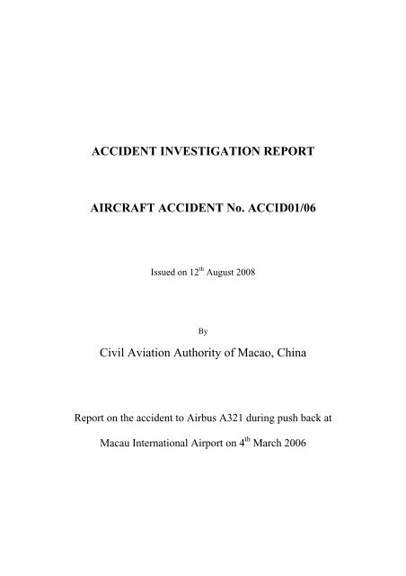
ACCIDENT INVESTIGATION REPORT<br />
AIRCRAFT ACCIDENT <strong>No</strong>. <strong>ACCID01</strong>/<strong>06</strong><br />
Issued on 12 th August 2008<br />
By<br />
Civil Aviation Authority of Macao, China<br />
<strong>Report</strong> on the accident to Airbus A321 during push back at<br />
Macau International Airport on 4 th March 20<strong>06</strong>
Content<br />
Synopsis.....................................................................................................................3<br />
1. Factual Information..........................................................................................4<br />
1.1. History of the Flight............................................................................................4<br />
1.2. Injuries to Persons...............................................................................................5<br />
1.3. Damage to <strong>Aircraft</strong> .............................................................................................5<br />
1.4. Other Damage.....................................................................................................6<br />
1.5. Personnel Information.........................................................................................10<br />
1.6. <strong>Aircraft</strong> Information............................................................................................11<br />
1.7. Meteorological Information................................................................................13<br />
1.8. Aids to Navigation..............................................................................................13<br />
1.9. ATC and Communications .................................................................................14<br />
1.10. Aerodrome Information....................................................................................14<br />
1.11. Flight Recorders ...............................................................................................16<br />
1.12. Wreckage and Impact Information................................................................. 16<br />
1.13. medical and Pathological Information..............................................................16<br />
1.14. Fire....................................................................................................................16<br />
1.15. Survival Aspects...............................................................................................16<br />
1.16. Test and Research.............................................................................................16<br />
1.17. Organizational and management Information..................................................18<br />
1.18. Additional Information.....................................................................................18<br />
2. Analysis..............................................................................................................18<br />
3. Conclusion .........................................................................................................21<br />
Page 1
4. Safety Recommendations .................................................................................22<br />
5. Appendices.........................................................................................................22<br />
Page 2
Operator<br />
: Air Macau Company Limited<br />
<strong>Aircraft</strong> Type : Airbus A321-231<br />
Registration<br />
Flight Number<br />
Place of <strong>Accident</strong><br />
: B-MAJ<br />
: NX628<br />
: Macau International Airport <strong>Aircraft</strong> Stand B4<br />
Latitude : 2209.40N<br />
Longitude : 11334.47E<br />
Date and Time<br />
: 4 th March 20<strong>06</strong> at <strong>06</strong>30 UTC (daylight)<br />
SYNOPSIS<br />
On 4 th March 20<strong>06</strong>, Air Macau A321-231 registration no. B-MAJ was being<br />
pushed back using a tow bar and a tractor operated by Menzies Macau Airport<br />
Services. After the aircraft had been moved backward for approximately 4<br />
meters, the tow bar head assembly broke up and the aircraft came to a sudden<br />
halt causing injuries to 2 cabin crewmembers and 1 passenger on board. The<br />
aircraft also sustained minor damage in the tow bar attachment. As the passenger<br />
sustained bone fracture and required hospitalization for more than 48 hours, it<br />
was classified as an accident. The Civil Aviation Authority – Macao, China<br />
(AACM) therefore conducted an investigation to the circumstances of the<br />
accident in accordance with AACM <strong>Aircraft</strong> <strong>Accident</strong> /Incident <strong>Investigation</strong><br />
Procedure.<br />
The investigation concluded that the operation of tractor and the mechanical<br />
structure of the tow bar are not the causal factor of this accident. The reason of the<br />
Page 3
jerk is not able to be determined according to the information available.<br />
However, 2 safety recommendations have been raised in regard to cabin safety.<br />
1. Factual Information<br />
1.1. History of the Flight<br />
On 4 th March 20<strong>06</strong>, Air Macau A321-231 registration no. B-MAJ flight no.<br />
NX107 arrived at its home base Macau International Airport from Pudong<br />
(PVG) International Airport, Shanghai at 0538 UTC. The only defect<br />
reported by the pilot was one inoperative coffee maker in the FWD galley.<br />
After replacement of the coffee maker and refueling, the aircraft was ready<br />
to continue its service to Taipei International Airport (TPE) under flight no.<br />
NX628 with 178 passengers, 2 flight crewmembers and 5 cabin<br />
crewmembers on board.<br />
At <strong>06</strong>40 UTC, Menzies Ramp Operations staff has connected the tractor<br />
Model FMC B600 to the nose landing gear of the aircraft via a tow bar<br />
model Clyde 15F2284. At that time, Air Macau maintenance technician<br />
was performing the handset communication with the cockpit. The Pilot-incommand<br />
of NX628, confirmed aircraft ready for push back with aircraft<br />
nose facing north. After confirming parking brake released and<br />
confirmation with the captain, the Air Macau maintenance technician gave<br />
hand signal to tractor driver indicating commencement of push back. The<br />
accident happened after the aircraft had been moved backward for<br />
approximately 4 meters.<br />
Page 4
A female passenger on wheelchair, aged 60, was the last passenger getting<br />
on board NX628. After boarding completed and all doors closed for<br />
approximately 2 minutes, aircraft push back started. At that time, the<br />
aforementioned passenger was walking towards the FWD toilet. Suddenly,<br />
the aircraft jerked to a stop. She lost her balance and fell down. Two other<br />
cabin crewmembers working in the FWD galley area at that time also fell<br />
down during the jerk. The passenger ended up on the top of a cabin<br />
crewmember’s legs hurting her back and feeling dizzy. Both of the cabin<br />
crewmember claimed having their back injured. One of them claimed that<br />
she could not move.<br />
The passenger and the two cabin crewmembers were sent to Kiang Wu<br />
Hospital for medical check up. One of the cabin crew members was<br />
released from the hospital on the same day. The passenger sustained bone<br />
fracture on her spine and required hospitalization for more than 48 hours.<br />
1.2. Injuries to Persons<br />
Crew Passenger Others<br />
Fatal 0 0 0<br />
Serious 0 1 0<br />
Minor 0 0 2<br />
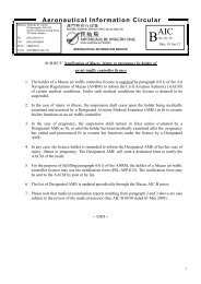
1.3. Damage to <strong>Aircraft</strong><br />
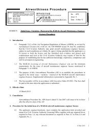
The damage to aircraft is minor. The tow bar attachment fitting at the nose<br />
landing gear of the aircraft was damaged due to excessive loading. As a<br />
shock absorbent design feature of the fitting, two bolts connecting a tube<br />
Page 5
in this fitting had broken and the tube was pushed inwards as shown in<br />
Figure 1.3.1 and 1.3.2.<br />
Figure 1.3.1<br />
Figure 1.3.2<br />
After replacement of the fitting, the aircraft was dispatched to service.<br />
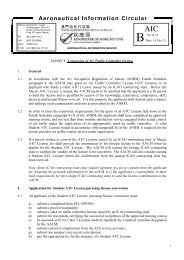
1.4. Other Damage<br />
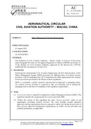
Towbar no. RTB18 involved in this accident has sustained damage in its<br />
towbar head assembly and head-to-tube connector.<br />
Page 6
The tow bar involved in this accident is made by Clyde, model no.<br />
15F2284 suitable for the use on A319/320/321. According to Menzies’<br />
record, this tow bar was received on <strong>No</strong>v 1997.<br />
Figure 1.4.1<br />
Figure 1.4.2<br />
Figure 1.4.1 and 1.4.2 above shows a towbar of the same model. The<br />
towbar head assembly is attached to the main tube through the head–totube<br />
connector by three bolts. The bolts at the two ends were shear bolts.<br />
The middle one is fitted into a hole larger than a normal bolt hole, so that<br />
Page 7
during operation, the shear load is transmitted through the two shear bolts.<br />
The middle bolt is of size of about 16 mm in diameter, and will take the<br />
shear load when the two shear bolt fail. The function of the shear bolts is<br />
to act as a safeguard against turning too abruptly, or at an angle which is<br />
too sharp during the pushback operation.<br />
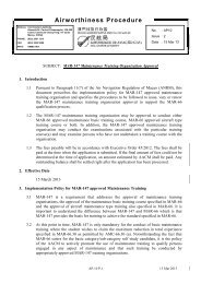
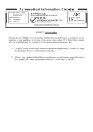
In this accident, all three bolts attaching the towbar head assembly to the<br />
head-to-tube connector were broken. As a result, the towbar head assembly<br />
liberated from the towbar. The upper plate of the head assembly, broken<br />
off from the main body near its welded joint, ended underneath the nose<br />
wheel. The lower plate was bent by almost 110 o and rested at the back of<br />
the nose wheel (as shown in Figure 1.4.3 to 1.4.6).<br />
Figure 1.4.3<br />
Page 8
Figure 1.4.4<br />
Figure 1.4.5<br />
Figure 1.4.6<br />
Page 9
1.5. Personnel Information<br />
1.5.1. Flight Crew<br />
Pilot-in-Command: Male, aged 49<br />
License:<br />
Medical:<br />
Macau, China ATPL(A)<br />
Class One<br />
Date of Exam 01/09/05<br />
Valid until 13/03/<strong>06</strong><br />
Co-pilot: Male, aged 33<br />
License:<br />
Medical:<br />
Macau, China CPL(A)<br />
Class One<br />
Date of Exam 25/08/05<br />
Valid until 25/08/<strong>06</strong><br />
1.5.2. Cabin Crew<br />
Chief Flight Attendant: Female, aged 27<br />
Certificate:<br />
Macau, China Crew Member Certificate<br />
(CMC) valid until 31/12/<strong>06</strong><br />
Leading Flight Attendant: Female, aged 20<br />
Certificate: Macau, China CMC valid until 11/08/<strong>06</strong><br />
Flight Attendant 3: Female, aged 24<br />
Certificate: Macau, China CMC valid until 30/11/<strong>06</strong><br />
Flight Attendant 4: Female, aged 21<br />
Certificate: Macau, China CMC valid until 30/04/07<br />
Flight Attendant 5: Male, aged 23<br />
Certificate: Macau, China CMC valid until 31/05/07<br />
Page 10
1.5.3. Operator of tractor<br />
The operator of the tractor, has joined Menzies Macau Ariport<br />
Services since August 2001. According to Menzies, he is one of the<br />
most experience staff in ramp operation. His training is shown as<br />
follow:<br />
Training Date Passed Re-training<br />
Induction training<br />
Aviation Security<br />
2-Sep-01<br />
Basic Ramp Operations 2-Sep-01<br />
Dangerous Goods Awareness 2-Sep-01 16-Aug-04<br />
Manual Handling Operations 2-Sep-01 9-Dec-04<br />
Ramp Safety<br />
2-Sep-01<br />
Thunderstorm Warning Signals 2-Sep-01 21-Aug-03<br />
Equipment training<br />
Tractor<br />
2-Sep-01<br />
Belt Loader 2-Sep-01 10-Aug-03<br />
Ground Power Unit<br />
12-Sep-02<br />
Air Condition Unit<br />
12-Sep-02<br />
Air Start Unit<br />
12-Sep-02<br />
Cargo Loader<br />
12-Sep-02<br />
Passenger Stair Truck<br />
2-Jan-04<br />
Conventional <strong>Aircraft</strong> Tractor 2-Jan-04<br />
Fuel Truck<br />
3-Jan-02<br />
Development Programme<br />
Telair International – B744 PDU 13-Mar-03<br />
& Inplane System<br />
Job responsibility and<br />
13-May-03<br />
Communication<br />
Safety Alert Refresher Briefing 28-Oct-03<br />
03<br />
Fire Safety Seminar<br />
12-Jan-05<br />
MD11F Loading and Unloading 7-Apr-05<br />
Briefing<br />
BR Ramp OPS Awareness<br />
Campaign 05<br />
12-Jul-05<br />
1.6. <strong>Aircraft</strong> Information<br />
1.6.1. General<br />
Manufacturer<br />
Airbus<br />
Page 11
Type A321-231<br />
<strong>Aircraft</strong> Serial <strong>No</strong>. MSN 908<br />
Year of Manufacturer 1998<br />
Certificate of Registration<br />
Certificate of Airworthiness<br />
Engines<br />
Maximum Take Off Weight<br />
<strong>No</strong>. 1/99 issued on 4 Feb 1999 to<br />
Air Macau<br />
<strong>No</strong>. 1/99 issued to Air Macau<br />
under Commercial Air Transport<br />
(passenger) Category<br />
Two International Aero Engines<br />
V2533-A5<br />
89000kg<br />
1.6.2. Tow Tractor<br />
The Model number of the tow tractor involved in the accident is<br />
FMC B600, designed to handle aircraft up to the B767 and A310.<br />
After the accident, Menzies continued to operate the tractor<br />
concerned for push back without any anomaly reported. Some of<br />
the maintenance tasks performed prior to the accident are shown as<br />
follow:<br />
Date Maintenance Task Type<br />
31 Jan <strong>06</strong> Rebuilt gear shifter Defect<br />
13 Jan <strong>06</strong> Replace engine oil and filters,<br />
lubricate all areas, replace<br />
transmission fluid and adjust hand<br />
brake<br />
rectification<br />
Preventive<br />
maintenance<br />
2 Jan <strong>06</strong> Replace new tires front Defect<br />
rectification<br />
Page 12
1.6.3. Tow Bar<br />
The tow bar involved in this accident is made by Clyde, model no.<br />
15F2284 suitable for the use on A319/320/321. According to<br />
Menzies’ record, this tow bar was received on <strong>No</strong>v 1997.<br />
Some of the maintenance tasks performed prior to the accident are<br />
shown as follow:<br />
Date Maintenance Task Type<br />
24 Dec 05 Perform PM Preventive<br />
maintenance<br />
9 <strong>No</strong>v 05 Replace cable pin Defect<br />
rectification<br />
14 Oct 05 Perform 90 day inspection, replace shear<br />
bolts lube all areas, replace ball pin<br />
Preventive<br />
maintenance<br />
1.7. Meteorological Information<br />
Meteorological report (METAR) at Macau International Airport near the<br />
time of accident was summarized as follows:<br />
<strong>Report</strong> time:<br />
Surface Wind:<br />
Visibility:<br />
<strong>06</strong>30 UTC<br />
040º - 04 kt<br />
8000 meters<br />
Lowest Cloud: few at 2000<br />
Temperature: 16 ºC<br />
Dew point: 10 ºC<br />
QNH:<br />
1017 hectopascals<br />
1.8. Aids to Navigation<br />
<strong>No</strong>t Applicable<br />
Page 13
1.9. ATC and Communications<br />
The accident took place at parking stand B4 at Macau International Airport.<br />
After the boarding was completed and all doors were closed, NX628<br />
received the pushback clearance from Macau Ground Frequency 121.725<br />
MHz.<br />
After the “Before Start checklist” completed, Pilot-in-Command of NX628<br />
contacted the ground staff to start the pushback. According to the<br />
interviews of both pilots after the accident, the Pilot-in-Command released<br />
the parking brake and co-pilot confirmed the brake pressure check zero<br />
prior to the pushback commenced which in according with the company<br />
SOP.<br />
After the aircraft was pushed back for several meters, the aircraft jerked.<br />
<strong>No</strong> engine was started or being started. The ground staff contacted the<br />
flight crew and requested to set the parking brake on. The ground staff<br />
informed the flight crew that the towbar was broken. The co-pilot<br />
informed Macau Ground that NX628 aborted the push back.<br />
The Chief Flight Attendant informed the Pilot-in-Command that a<br />
passenger fell down in the cabin and was injured. The Pilot-in-Command<br />
reported the situation to Macau Ground and Air Macau Operation Control<br />
Center and requested medical assistance.<br />
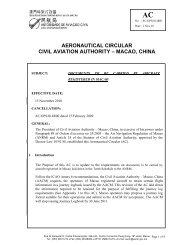
1.10. Aerodrome Information<br />
Figure 1.10.1 depicts the aircraft stands schematic of Macau International<br />
Airport. Stand B4 is one of the four aircraft stands with loading bridge<br />
Page 14
facility. After the accident, the apron surface was confirmed to be flat and<br />
undamaged. <strong>No</strong> foreign object was found in the vicinity of stand B4.<br />
Figure 1.10.1<br />
Page 15
1.11. Flight Recorders<br />
During the time of the accident, as both of the engines have not been<br />
started, all the recorders including flight data recorder, cockpit voice<br />
recorder and the QAR, were not recording.<br />
1.12. Wreckage and Impact Information<br />
<strong>No</strong>t Applicable<br />
1.13. Medical and Pathological Information<br />
<strong>No</strong>t Applicable<br />
1.14. Fire<br />
<strong>No</strong>t Applicable<br />
1.15. Survival Aspects<br />
<strong>No</strong>t Applicable<br />
1.16. Test and Research<br />
After the accident, the Civil Aviation Authority-Macao, China, has<br />
instructed Menzies Macau Airport Services to approach CityU<br />
Professional Services Ltd for metallurgical analysis of the damaged towbar.<br />
The study included a sit investigation, materials examination of the towbar<br />
head assembly material and the bolt material using a stereomicroscope and<br />
a scanning electron microscope(SEM). Tensile tests were also carried out<br />
to determine the tensile properties of the plates in the head assembly, and<br />
Page 16
the material of bolts. The damaged towbar fitting from the aircraft and two<br />
new shear bolts were also provided for examination.<br />
The report prepared by CityU Professional Services Ltd, dated 10 May<br />
20<strong>06</strong>, concluded that :<br />
a. The welded joint and the surrounding material in the towbar head<br />
assembly did not contain observable defects.<br />
b. Sudden deceleration such as aircraft wheel braking provided a sudden<br />
force on the towbar. The large shear bolt was most likely shear failed<br />
due to this action.<br />
c. The loss of the large shear bolt resulted in eccentricity of the towbar<br />
head, resulting in bending of the parallel plates of the towbar head<br />
assembly.<br />
d. When the deformation in the top plate became large, the middle bolt of<br />
about 16mm in diameter was sheared to failure.<br />
e. The top plate broke off from the head assembly when the local stress<br />
exceeded the ultimate tensile stress. The bottom plate continued to<br />
bend to its final shape.<br />
f. When the towbar was brought to rest, the head assembly was nearly on<br />
the ground.<br />
In the report, the force required to bend the towbar head assembly was<br />
calculated. Result of calculation shows that such excessive force is very<br />
unlikely to be attained by suddenly increase of power from the tractor.<br />
However, it is possible to attain such force by sudden deceleration from<br />
the aircraft side.<br />
Page 17
1.17. Organizational and management Information<br />
1.17.1. Air Macau Company Limited<br />
Air Macau Company Limited is a Macao based international airline<br />
operating to various cities in Mainland China and countries in<br />
South East Asia.<br />
1.17.2. Menzies Macau Airport Services Limited<br />
Menzies Macau Airport Services is a service provider of ground<br />
handling, cargo logistics, passenger handling, aircraft maintenance<br />
and aviation support services at the Macau International Airport.<br />
1.18. Additional Information<br />
<strong>No</strong>t Applicable<br />
2. Analysis<br />
2.1. <strong>Aircraft</strong> Airworthiness<br />
All other aircraft systems, including aircraft brake system, were<br />
functioning properly.<br />
2.2. Tractor Operation<br />
The tractor driver was properly trained in terms of initial and recurrent<br />
training. After working in the ramp operation for more than 5 years, he is<br />
well-experienced on ramp operation and the equipment concerned. Both<br />
the tractor and the towbar concerned were properly maintained. As<br />
mentioned in Section 1.16, metallurgical analysis revealed that there was<br />
no observable defects on the towbar head assembly. It is also very unlikely<br />
that the force causing the breakage of the towbar can be attained by<br />
Page 18
suddenly increase of power from the tractor. There was no evidence<br />
indicating tractor operation was a contributing factor to the accident.<br />
2.3. Cause of towbar breakage<br />
As one of the conclusion in the metallurgical analysis, breakage of the<br />
towbar was caused by sudden deceleration of the aircraft. The<br />
investigation team speculated there could be two possible scenarios<br />
causing such deceleration:<br />
Scenario A - <strong>Accident</strong>al application of brake by pilot<br />
During the push back operation, if the pilot applies aircraft brake or<br />
parking brake, it can bring the aircraft to a rapid deceleration. As<br />
indicated in the analysis report from CityU Professional Services<br />
Ltd., aircraft braking can cause an excessive force to the towbar<br />
resulting to a damage like in this event. Also, in the statement<br />
provided by the tractor driver, he emphasized that right after he<br />
noticed the breakage of the towbar, he found the parking brake<br />
indication light on the nose gear of the aircraft was on. The pilot<br />
statements assured that no brake or parking brake was applied until<br />
the ground staff requested to do so. However, it cannot be verified<br />
by QAR or FDR due to the fact that both were not activated before<br />
the engine start.<br />
Scenario B. Foreign object blocking the aircraft in movement<br />
There was also the possibility that certain foreign object, such as a<br />
wheel chock not properly removed prior to the push back operation,<br />
blocked one of the wheel and jammed the aircraft in movement to a<br />
Page 19
sudden halt. Such foreign object could have been removed from the<br />
accident scene after the accident.<br />
The investigation team has no sufficient information to conclude<br />
which of the above scenario is the causal factor of this accident.<br />
2.4. Cabin safety during push back<br />
While the aircraft is moving, cabin crewmembers and passengers not<br />
secured to their seats are exposed to risk of injury from sudden stops. The<br />
cabin crewmembers were standing in the cabin performing various duties<br />
when the aircraft was being pushed back. Two cabin crewmembers in the<br />
front galley area fell over and sustained minor injuries when the aircraft<br />
came to a sudden stop.<br />
One passenger walking towards the front cabin toilet during the aircraft<br />
pushback fell over and sustained injuries and required hospitalization for<br />
more than 48 hours.<br />
Page 20
3. Conclusion<br />
3.1. Rapid deceleration from the aircraft side resulting to an excessive force on<br />
the towbar caused the failure of the towbar. Cause of rapid deceleration of<br />
the aircraft cannot be determined in the investigation.<br />
3.2. Due to the aircraft being pushed back came to a sudden halt, two cabin<br />
crewmembers and one passenger, who were not secured in their seats<br />
during that time, fell over and sustained injuries.<br />
Page 21
4. Safety Recommendations<br />
Safety Recommendation 20<strong>06</strong>-01<br />
During the aircraft surface movement, cabin crew members and passengers not<br />
secured to their seats are exposed to risk of injury from sudden stops. It is<br />
recommended that the aircraft operator<br />
(i) review the cabin crew tasks and duties during aircraft surface movement<br />
and restrict their tasks to those directly related to safety only; and<br />
(ii) review the operation policies and procedures to ensure that during aircraft<br />
surface movement, the cabin crewmembers are secured in their jump seats<br />
except when they have to perform any safety related duties.<br />
Safety Recommendation 20<strong>06</strong>-02<br />
It is recommended that the aircraft operator to review her operation policies and<br />
procedures to reinforce that the passengers are to be secured in their seats during<br />
the aircraft surface movement.<br />
5. Appendices<br />
Appendix A : Consultancy report from the CityU professional Services Ltd<br />
Page 22
Consultancy <strong>Report</strong><br />
Name of Client:<br />
Autoridade de Aviação Civil<br />
Região Administrativa Espeical de Macau<br />
Attn:<br />
Mr Brian C. W. Lai<br />
Head of Department<br />
Airworthiness<br />
Address of Client: R. Dr. Pedro José Lobo, 1-3<br />
Edif. Luso Internacional, 26º andar<br />
Macau<br />
Nature of Consultancy:<br />
<strong>Report</strong> Prepared by:<br />
Failure Analysis of a Towbar<br />
Dr C M Lawrence Wu<br />
BSc(Eng), DMS, PhD, AMRAeS<br />
Associate Professor<br />
Department of Physics and Materials Science<br />
City University of Hong Kong<br />
Date: 10 May 20<strong>06</strong>
CityU Professional Services Ltd<br />
Failure Analysis of a Towbar<br />
Department of Physics & Materials Science<br />
City University of Hong Kong<br />
1. Management Summary<br />
On behalf of the Autoridade de Aviação Civil, Região Administrativa Espeical de Macau,<br />
Menzies Macau Airport Services Ltd. (Menzies) commissioned CityU Professional Services<br />
Limited (CPS) to study the cause of failure of an A320 towbar. The incident occurred on the<br />
4 th March 20<strong>06</strong> at the Macau International Airport during the pushback of an Air Macau A321<br />
aircraft. Apparently, after the aircraft was pushed back for a few metres, failure occurred in<br />
the towbar. At the end of the incident, one of the metal plates in the towbar head assembly<br />
was found to break near a welded joint and the other one was bent substantially. A few bolts<br />
were also found broken.<br />
The study included a site investigation, and materials examination of the towbar head assembly<br />
material and the bolt material using a stereomicroscope and a scanning electron microscope<br />
(SEM). Tensile tests were also carried out to determine the tensile properties of the plates in the<br />
head assembly, and the material of a bolt of about 16 mm in diameter. The laboratory<br />
examination and test results were analysed, together with appropriate stress calculations.<br />
It was concluded that<br />
a. The welded joint and the surrounding material in the towbar head assembly did not<br />
contain observable defects.<br />
b. Sudden deceleration such as aircraft wheel braking provided a sudden force on the<br />
towbar. The large shear bolt was most likely shear failed due to this action.<br />
c. The loss of the large shear bolt resulted in eccentricity of the towbar head, resulting in<br />
bending of the parallel plates of the towbar head assembly.<br />
d. When the deformation in the top plate became large, the middle bolt of about 16 mm in<br />
diameter was sheared to failure.<br />
e. The top plate broke off from the head assembly when the local stress exceeded the<br />
ultimate tensile stress. The bottom plate continued to bend to its final shape.<br />
f. When the towbar was brought to rest, the head assembly was nearly on the ground.<br />
- 1 -
CityU Professional Services Ltd<br />
Failure Analysis of a Towbar<br />
Department of Physics & Materials Science<br />
City University of Hong Kong<br />
2. Introduction<br />
One of the services provided by the Menzies Macau Airport Services Ltd. (Menzies) at the<br />
Macau International Airport is aircraft transit arrangement, including push back of aircrafts.<br />
On 4 th March 20<strong>06</strong>, an incident occurred at the Macau International Airport during the<br />
pushback of an Air Macau A321 aircraft. After the aircraft had been pushed back for a few<br />
metres, failure occurred in the towbar. At the end of the incident, one of the metal plates in<br />
the towbar head assembly was found to break near a welded joint and another plate was bent<br />
substantially. On behalf of the Autoridade de Aviação Civil, Região Administrativa Espeical de<br />
Macau, Menzies has commissioned CityU Professional Services Limited (CPS) to study the<br />
cause of failure of the A320 towbar. The towbar was manufactured by Clyde Machines.<br />
Figure 2-1(a) shows a new head assembly of a towbar. One end of the head assembly consists<br />
of a U-channel with a half round shape at the bottom to receive the towbar fitting attached to the<br />
nose undercarriage. The other end consists of two parallel plates for connection to the head-totube<br />
assembly, which in turn connects to the main tube of the towbar with 12 bolts. The<br />
connection between the head assembly and the head-to-tube connector is with two shear bolts at<br />
either end, and a loosely fitted bolt of about 16 mm in diameter. This will be described in better<br />
details in Section 3. Figure 2-1(b) shows the towbar involved in the incident. In comparison<br />
with the new towbar head assembly, it can be seen that the top of the two parallel plates is<br />
broken off from the main body near its welded joint. Also, the bottom plate was bent by about<br />
110°. Nearly all of the bolts attaching the locking mechanism on the top of the head assembly<br />
were broken.<br />
(a) a new towbar head assembly<br />
(b) incident towbar head assembly (plate on<br />
RHS came off near the top welding position)<br />
Figure 2-1 : Appearance of incident towbar head assembly<br />
- 2 -
CityU Professional Services Ltd<br />
Failure Analysis of a Towbar<br />
Department of Physics & Materials Science<br />
City University of Hong Kong<br />
3. Site Visit on 30 March 20<strong>06</strong><br />
A site visit was carried out on the 30 March 20<strong>06</strong>, with the support of Menzies. Representatives<br />
from the Airworthiness Department of the Autoridade de Aviação Civil of Macau also attended<br />
the site visit. During the sit visit, a number of observations were made, including:<br />
a. Observation of a new Clyde A320 towbar for comparison with the incident one.<br />
b. Initial inspection of the incident towbar.<br />
c. Observation of a Clyde A320 towbar attached and pushed back an aircraft.<br />
Figures 2-1(a) and 3-1 show the incident towbar fitted with a new head assembly. So although<br />
the head assembly and the head-to-tube connector were damaged, the remaining parts of the<br />
towbar were serviceable. In particular, the main tube and the positions for the bolts as shown in<br />
Figure 2-1(a) were in good condition, and so the fitting of a new head-to-tube connector and<br />
head assembly was possible. In other words, the damage to the towbar in this case was to the<br />
head-to-tube connector and head assembly only.<br />
Figure 3-1 : The incident towbar fitted with a new head assembly<br />
The results on the examination of the damaged head-to-tube connector and head assembly<br />
will be provided in a Section 4 of this report and will not be repeated here. During the site<br />
visit, the investigator requested to examine the towing fitting attached at the nose<br />
undercarriage, and Menzies was able to borrow it from Air Macau for examination. It was<br />
then found that both bolts connecting a tube in this fitting had broken, as shown in Figure 3-<br />
2. So this part was requested to be on loan from Air Macau for laboratory examination. A<br />
section of the bolt shank to nut connection was found, and was very likely from one of the<br />
two broken bolts. This was placed at the hole in Figure 3-2(a) for illustration.<br />
- 3 -
CityU Professional Services Ltd<br />
Failure Analysis of a Towbar<br />
Department of Physics & Materials Science<br />
City University of Hong Kong<br />
(a) one side<br />
(b) other side<br />
Figure 3-2 : Broken bolts attaching the tube in the towing fitting<br />
A towbar attaching to the nose undercarriage of an A321 aircraft is shown in Figure 3-3. The<br />
details of attachment between the nose undercarriage and the towbar head assembly are<br />
shown in Figure 3-4. In particular, the towing fitting attached to the nose undercarriage<br />
contained a tube for quick connection to the towbar, and was locked into position during<br />
operation. It is noted that at this moment the other end of the towbar (with an eye) had not<br />
been attached to the tractor.<br />
Figure 3-3 : A towbar attaching to the nose undercarriage of an A321 aircraft<br />
- 4 -
CityU Professional Services Ltd<br />
Failure Analysis of a Towbar<br />
Department of Physics & Materials Science<br />
City University of Hong Kong<br />
Figure 3-4 : Details of nose undercarriage to towbar head assembly attachment<br />
Figure 3-5 shows that the attachment between the head assembly and the main tube of the<br />
towbar was by three bolts. The bolts at the two ends were shear bolts. The middle one is<br />
fitted into a hole larger than a normal bolthole, so that during operation, the shear load is<br />
transmitted through the two shear bolts. The middle bolt is of size of about 16 mm (5/8-inch)<br />
in diameter, and will take the shear load when the two shear bolt fail. In particular, the shear<br />
bolts act as safeguard against turning too abruptly, or at an angle which is too sharp during<br />
the pushback operation.<br />
Figure 3-5 : The wheels on towbar were retracted up after attaching towbar to tractor<br />
- 5 -
CityU Professional Services Ltd<br />
Failure Analysis of a Towbar<br />
Department of Physics & Materials Science<br />
City University of Hong Kong<br />
Just before the pushback, the other end of the towbar was attached to the tractor. The wheels<br />
on the towbar were then retracted up, as shown in Figure 3-6.<br />
Figure 3-6 : The wheels on towbar were retracted up after attaching towbar to tractor<br />
A number of measurements of the towbar were made. These are shown in Figure 3-7.<br />
Figure 3-7 : Measurements of towbar (wheel is 130 mm above ground when retracted)<br />
- 6 -
CityU Professional Services Ltd<br />
Failure Analysis of a Towbar<br />
Department of Physics & Materials Science<br />
City University of Hong Kong<br />
4. Initial Examination<br />
The samples, having been identified during the site visit, were transported to the investigator at<br />
City University of Hong Kong for detail examination. Figure 4-1 shows the samples as received<br />
from Menzies. Apart from the pieces from the head assembly, the samples also consist of the<br />
towbar fitting on loan from Air Macau and the head-to-tube connector. Two new shear bolts<br />
were also provided for comparison. It is noted that at a later stage, three bolts of about 16 mm<br />
(5/8-inch) in diameter were also provided by Menzies for tensile test.<br />
Figure 4-1 : Samples as received from Menzies<br />
Figure 4-2(a) shows that the tip on the left-hand side of the plate of the head-to-tube connector<br />
was bent upwards. This is shown more clearly in Figure 4-2(b), in which a straight red lie was<br />
drawn to show that the plate was bent. A bushing at this position was also seen to rotate<br />
clockwise.<br />
(a) front view<br />
(b) bent tip and rotated bushing<br />
Figure 4-2 : Appearance of head-to-tube connector<br />
- 7 -
CityU Professional Services Ltd<br />
Failure Analysis of a Towbar<br />
Department of Physics & Materials Science<br />
City University of Hong Kong<br />
Figure 4-3(a) shows the top view of the head-to-tube connector. The positions for the shear<br />
bolts are indicated with red arrows. The remains of the shear bolt on the right-hand side (RHS)<br />
can still be seen. Figure 4-3(b) shows the rotated bushing as seen in Figure 4-2(b). The other<br />
shear bolt, originally installed through the centre hole of the bushing, was broken and its remains<br />
can be seen in this figure. This shear bolt has a smaller diameter than that on the RHS. The<br />
middle hole seen in Figure 4-3(a) provides a loose fit for the bolt of about 16 mm diameter, as<br />
shown in Figure 3-5. Under close examination, the RHS of the hole wall was found to have<br />
dented near the top surface. This shows that a large shear force was applied at this position on<br />
the bolt of about 16 mm in diameter.<br />
(a) top view<br />
(b) bushing moved forward<br />
Figure 4-3 : Top view of head-to-tube connector<br />
Figure 4-4 : RHS of hole wall dented near top surface<br />
- 8 -
CityU Professional Services Ltd<br />
Failure Analysis of a Towbar<br />
Department of Physics & Materials Science<br />
City University of Hong Kong<br />
It is clear that the large shear bolt was cleanly sheared off at the top and bottom surface positions<br />
of the plate in head-to-tube connector. This is because the fracture surfaces on the top and<br />
bottom surfaces are very flat, as shown in Figures 4-5(a) and 4-5(b) respectively.<br />
As shown in Figure 4-3(b), the small shear bolt went through the centre of a bushing, which can<br />
be slid along a groove. So when the shearing action occurred, the small shear bolt was likely not<br />
shear-failed straight away. Instead, the bushing was pushed toward the main tube of the towbar.<br />
Due to the interaction between the head-to-tube connector and the bottom plate of the head<br />
assembly, as will be explained later, the small shear bolt was later pulled and sheared to the<br />
shape as shown in Figures 4-6(a) and 4-6(b). Also, the bent appearance of the shear bolt<br />
suggests that a large force existed to shear the bottom plate of the head assembly and the headto-tube<br />
connector apart. As the two parts were not clamped together, the section of the shear<br />
bolt originally residing in the bottom plate of the head assembly was pulled out and bent. It was<br />
also seen in Figures 4-6(a) and 4-6(b) that large deformation occurred in the groove, as well as a<br />
part of the bushing broken off, indicating a large force involved.<br />
(a) on top surface<br />
(b) on bottom surface<br />
Figure 4-5 : Large shear bolt fracture surfaces<br />
(a) view showing broken side of bushing<br />
(b) view showing highly deformed groove<br />
Figure 4-6 : Small shear bolt fracture surfaces<br />
- 9 -
CityU Professional Services Ltd<br />
Failure Analysis of a Towbar<br />
Department of Physics & Materials Science<br />
City University of Hong Kong<br />
Figure 4-7 shows the damaged head assembly. The top plate, which has the appearance as<br />
shown in Figure 4-8(a), broke off. Figure 4-8(b) indicates that the top plate was subjected to<br />
bending in the orientation as shown before fracture.<br />
Figure 4-7 : Damaged head assembly<br />
(a) Top plate broken off from head assembly<br />
(b) Top plate bent before broken off<br />
Figure 4-8 : Plates in head assembly broken and bent<br />
- 10 -
CityU Professional Services Ltd<br />
Failure Analysis of a Towbar<br />
Department of Physics & Materials Science<br />
City University of Hong Kong<br />
The fracture surface on the broken off top plate is shown in Figure 4-9. It can be seen that the<br />
bottom part of the fracture surface contained tensile fracture as well as signs of bending, causing<br />
the appearance of layer separation. Figure 4-10 is the other part of the fracture surface, i.e. the<br />
one at the head assembly end. It is noted that the bottom plate was sawn off near the welded<br />
joint so as to reveal the fracture surface easily. Apart from having a fracture surface similar to<br />
that in Figure 4-9, this figure also contains evidence that the middle part, as well as the fracture<br />
surface, were subjected to indentation from a certain object. This will be explained later.<br />
Figure 4-9 : Fracture surface of top plate<br />
Figure 4-10 : Fracture surface of top plate at head assembly end<br />
- 11 -
CityU Professional Services Ltd<br />
Failure Analysis of a Towbar<br />
Department of Physics & Materials Science<br />
City University of Hong Kong<br />
Figure 4-11 : Fracture surface of top plate at head assembly end<br />
Figure 4-12 shows the curved section of the bottom plate. Some rub marks were found, and<br />
were correlated to the parts at the tip section of the head-to-tube connector.<br />
Figure 4-12 : Bent bottom plate with rub marks caused by parts of the head-to-tube connector<br />
- 12 -
CityU Professional Services Ltd<br />
Failure Analysis of a Towbar<br />
Department of Physics & Materials Science<br />
City University of Hong Kong<br />
Figure 4-13 shows the bottom surface and end of the head assembly. A number of indentation<br />
marks as marked in red arrows were identified.<br />
Figure 4-13 : Bottom surface of the metal block of the head assembly with indentation marks<br />
The broken bolts of about 16 mm in diameter were then examined. It can be seen in Figure 4-14<br />
that fracture occurred at the interface position between the top plate of the head assembly and<br />
the plate of the head-to-tube connector. The fracture surfaces of this bolt are shown in Figure 4-<br />
14. The fracture surface were very flat, and contained evidence that they were shear fractured.<br />
Figure 4-15 illustrates that fracture occurred between the top plate and the head-to-tube<br />
connector.<br />
(a) Bolt broken in two<br />
(b) Fracture surfaces of broken bolt<br />
Figure 4-14 : Broken bolt of about 16 mm in diameter<br />
- 13 -
CityU Professional Services Ltd<br />
Failure Analysis of a Towbar<br />
Department of Physics & Materials Science<br />
City University of Hong Kong<br />
Figure 4-15 : Lower part of the broken bolt (about 16 mm dia.)<br />
illustrating fracture between top plate and head-to-tube connector<br />
Figure 4-16 shows new large and small shear bolts, as well as the remains of the shear bolts<br />
from the incident.<br />
Figure 4-16 : Large and small shear bolts<br />
- 14 -
CityU Professional Services Ltd<br />
Failure Analysis of a Towbar<br />
Department of Physics & Materials Science<br />
City University of Hong Kong<br />
Figure 4-17 shows the fracture surface of the large shear bolt. It can be seen that he fracture<br />
surface is very flat.<br />
Figure 4-17 : Fracture surface of large shear bolt<br />
- 15 -
CityU Professional Services Ltd<br />
Failure Analysis of a Towbar<br />
Department of Physics & Materials Science<br />
City University of Hong Kong<br />
5. Examination with Scanning Electron Microscope (SEM)<br />
Examination with scanning electron microscope (SEM) was employed to study the bolt material<br />
and the welded joints of the head assembly to confirm their integrity. Figure 5-1 shows the<br />
fracture surface of the bolt of about 16 mm in diameter (shown in Figure 4-14(b) before).<br />
Figure 5-1(a) is a low magnification micrograph, showing the bolt was sheared from left to<br />
right. Figure 5-1(b) is a high magnification micrograph, confirming that shearing of the bolt<br />
was from left to right.<br />
(a) Low magnification<br />
(b) High magnification<br />
Figure 5-1 : SEM fractographs of bolt of about 16 mm diameter<br />
Figure 5-2 shows the fracture surface of the large shear bolt shown in Figure 4-17 before.<br />
Figure 5-2(a) is a low magnification micrograph. Figure 5-2(b) is a high magnification<br />
micrograph, confirming that shearing of the bolt was from left to right. This material is seen to<br />
be softer than that of the bolt in Figure 5-1.<br />
(a) Low magnification<br />
(b) High magnification<br />
Figure 5-2 : SEM fractographs of large shear bolt<br />
- 16 -
CityU Professional Services Ltd<br />
Failure Analysis of a Towbar<br />
Department of Physics & Materials Science<br />
City University of Hong Kong<br />
The head assembly is made from a metal block, welded with two horizontal plates. The welded<br />
joint of the head assembly was first sectioned at an appropriate location, as shown in Figure 5-<br />
3(a). Grinding, polishing and etching were carried out as shown in Figure 5-3(b), so as to reveal<br />
the microstructure. Figures 5-4(a) and 5-4(b) show typical microstructures at welded joints.<br />
They both show good weld interfaces between weld metal and metal block or plate.<br />
(a) slice on the LHS for examination<br />
(b) polished and etched surface<br />
Figure 5-3 : Cross-section sample for examination of welded joints<br />
(a) bottom LH weld<br />
(b) top RH weld<br />
Figure 5-4 : SEM micrographs of welded joints<br />
- 17 -
CityU Professional Services Ltd<br />
Failure Analysis of a Towbar<br />
Department of Physics & Materials Science<br />
City University of Hong Kong<br />
Figures 5-5, 5-6 and 5-7 show the microstructures of the weld metal, block metal and plate<br />
metal respectively. It can be seen that the plate material is relatively soft. However, the<br />
microstructure of the three types of material are in good order.<br />
Figure 5-5 : Microstructure of welded metal<br />
Figure 5-6 : Microstructure of block metal<br />
- 18 -
CityU Professional Services Ltd<br />
Failure Analysis of a Towbar<br />
Department of Physics & Materials Science<br />
City University of Hong Kong<br />
Figure 5-7 : Microstructure of plate metal<br />
- 19 -
CityU Professional Services Ltd<br />
Failure Analysis of a Towbar<br />
Department of Physics & Materials Science<br />
City University of Hong Kong<br />
6. Tensile Tests<br />
In order to obtain the tensile strength of the bolt and the plate materials, tensile test were carried<br />
out as per EN10002 Part 1. Tensile specimens with circular cross-section of about 3.8 mm in<br />
diameter at the gauge length were manufactured from the bolt or plate material. The results of<br />
the tensile test are shown in Tables 6-1 and 6-2 for the bolt and plate material, respectively.<br />
Table 6-1 : Tensile test results of material of bolt of about 16 mm diameter<br />
Sample<br />
Ultimate tensile<br />
stress (MPa)<br />
Yield stress<br />
(MPa)<br />
Elongation<br />
(%)<br />
1 953 857 12.0<br />
2 965 870 12.8<br />
3 943 832 14.4<br />
Average 954 853 13<br />
Table 6-2 : Tensile test results of plate material<br />
Ultimate tensile Yield stress Elongation<br />
Sample<br />
stress (MPa)<br />
(MPa)<br />
(%)<br />
1 434 274 25.6<br />
2 432 283 38.4<br />
3 437 321 36.4<br />
Average 434 293 33<br />
- 20 -
CityU Professional Services Ltd<br />
Failure Analysis of a Towbar<br />
Department of Physics & Materials Science<br />
City University of Hong Kong<br />
7. Analysis<br />
According to the information given to the investigator, the pushback was carried out as normal<br />
for about 5 m, then suddenly the towbar head broke. The above examinations have indicated<br />
how the parts in the towbar head assembly were related to each other during the incident. Figure<br />
7-1 is a mock-up of the final positions of the relevant parts when the towbar came to a rest.<br />
Then, by further relating the head assembly with the main remaining parts of the towbar, the<br />
towbar position in relation to the undercarriage can be determined, and is shown in Figure 7-2.<br />
Figure 7-1 : Final resting position of towbar head assembly<br />
Figure 7-2 : Final resting position of towbar<br />
- 21 -
CityU Professional Services Ltd<br />
Failure Analysis of a Towbar<br />
Department of Physics & Materials Science<br />
City University of Hong Kong<br />
It is first noted that the examination of the microstructure revealed no problem with materials<br />
at the weld areas. That is, the materials were not adversely affected.<br />
In arriving at the final shape of the towbar head as shown Figure 7-2, it is likely that the<br />
following sequence of event occurred:<br />
a. The large shear bolt was shear fractured.<br />
b. Due to the weight distribution of the towbar and the loss of the large shear bolt, an<br />
eccentricity, say 10 mm, was set up, leading to bending stress on the plates due to the<br />
applied pushing force from the tractor.<br />
c. The top plate bent. When bending increased, the bolt of about 16 mm in diameter was<br />
sheared. The bending action continued very fast with the plates going down toward the<br />
ground. That is, the main tube rotated.<br />
d. The top plate broke off when it reached the maximum stress bearable at the root of the<br />
plate. Bending continued with the bottom plate, until it was folded into the shape as<br />
shown in Figure 7-1.<br />
The second moment of area, I, of the top or bottom plate is = (101)(13) 3 /12 = 18491 mm 4 .<br />
Assuming that bending is initially dominant at one of the plate, i.e. the top plate, and that if there<br />
is a 10 mm eccentricity, then there exist a moment on this plate. Using Engineer’s Theory of<br />
bending, the bending stress = (P)(10)(6.5)/18491. If the bending stress is greater than the yield<br />
stress, then permanent deformation will occur. In Table 2, the yield stress of the plate material<br />
was found to be 293 MPa. Using this information, P is found to be 83,351 N. When this force<br />
was attained, the top plated was bent, causing the gradual bending of the bottom plate at the<br />
same time. As the top plate deformed, it moved relatively to the plate of the head-to-tube<br />
connector. Although the hole in the plate of the head-to-tube connector was nearly double that<br />
of the bolt, the large shear deformation cause shearing of the bolt of about 16 mm in diameter.<br />
Subsequently the deformation happened even faster. The results in Table 6-1 show that the<br />
ultimate tensile stress (UTS) of the bolt material is 954 MPa. The ultimate shear stress can be<br />
estimated by multiplying 0.4 to the UTS. So the ultimate shear stress is 382 MPa. As the area of<br />
the bolt is known, the minimum force required to shear fracture this bolt is 74,420 N. This was<br />
seen to be possible as P was larger than this value initially to cause the bending of the top plate.<br />
When the value of P > 83,351 N, the large shear bolt would have failed first. This is the main<br />
reason for the set up of the eccentricity, due to the weight of various parts in the towbar.<br />
When the pushback action occurs at constant speed, the force acting in the towbar is small.<br />
Although the total weight of the A321 aircraft during pushback can be about 90,000 kg, the<br />
tractor only needs to overcome the friction in the wheel bearings and the tyres of the aircraft to<br />
commence pushback. The force required will be much less than 83,351 N. So this action will<br />
not cause bending of the top plate.<br />
Assuming that there is a sudden deceleration in the aircraft, then the towbar will see a force from<br />
the tractor. As mentioned above, if the force is larger than 83,351 N, the middle bolt will be<br />
sheared. It is known that the mass of the tractor is 27,273 kg (60,000 lbs), and so the<br />
deceleration required is 83351/27273 = 3.1 m/s 2 . If the aircraft is being pushed back with an<br />
approximate speed of 0.67 m/s (1.5 mph), and the aircraft is brought to rest in 0.2 s, the<br />
- 22 -
CityU Professional Services Ltd<br />
Failure Analysis of a Towbar<br />
Department of Physics & Materials Science<br />
City University of Hong Kong<br />
deceleration will be 3.3 m/s 2 . So the breaking of the towbar head assembly is possible if sudden<br />
deceleration occurred.<br />
It is very unlikely to be able to apply the excessive force by suddenly increasing the power from<br />
the tractor. However, it is possible to provide the loading through the sudden deceleration, e.g.<br />
by braking in the aircraft wheels.<br />
- 23 -
CityU Professional Services Ltd<br />
Failure Analysis of a Towbar<br />
Department of Physics & Materials Science<br />
City University of Hong Kong<br />
8. Conclusions<br />
It was concluded that<br />
a. The welded joint and the surrounding material in the towbar head assembly did not<br />
contain observable defects.<br />
b. Sudden deceleration such as aircraft wheel braking provided a sudden force on the<br />
towbar. The large shear bolt was most likely shear failed due to this action.<br />
c. The loss of the large shear bolt resulted in eccentricity of the towbar head, resulting in<br />
bending of the parallel plates of the towbar head assembly.<br />
d. When the deformation in the top plate became large, the middle bolt of about 16 mm in<br />
diameter was sheared to failure.<br />
e. The top plate broke off from the head assembly when the local stress exceeded the<br />
ultimate tensile stress. The bottom plate continued to bend to its final shape.<br />
f. When the towbar was brought to rest, the head assembly was nearly on the ground.<br />
- 24 -