4 Hp/Straight Line/Rear Exhaust Die Grinder - Dynabrade Inc.
4 Hp/Straight Line/Rear Exhaust Die Grinder - Dynabrade Inc.
4 Hp/Straight Line/Rear Exhaust Die Grinder - Dynabrade Inc.

Create successful ePaper yourself
Turn your PDF publications into a flip-book with our unique Google optimized e-Paper software.
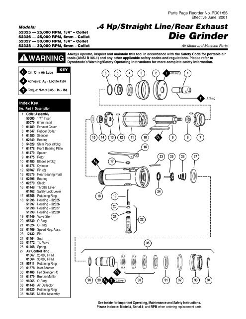
Models:<br />
52325 — 25,000 RPM, 1/4" – Collet<br />
52326 — 25,000 RPM, 6mm – Collet<br />
52327 — 30,000 RPM, 1/4" – Collet<br />
52328 — 30,000 RPM, 6mm – Collet<br />
Parts Page Reorder No. PD01•56<br />
Effective June, 2001<br />
.4 <strong>Hp</strong>/<strong>Straight</strong> <strong>Line</strong>/ <strong>Rear</strong> <strong>Exhaust</strong><br />
<strong>Die</strong> <strong>Grinder</strong><br />
Air Motor and Machine Parts<br />
Always operate, inspect and maintain this tool in accordance with the Safety Code for portable air<br />
tools (ANSI B186.1) and any other applicable safety codes and regulations. Please refer to<br />
<strong>Dynabrade</strong>’s Warning/Safety Operating Instructions for more complete safety information.<br />
O<br />
Oil: O 1 = Air Lube<br />
KEY<br />
6<br />
5<br />
4 3 2 T 28 N•m 1<br />
A<br />
T<br />
Adhesive: A 8 = Loctite #567<br />
Torque: N•m x 8.85 = In. - lbs.<br />
Index Key<br />
No. Part # Description<br />
1 Collet Assembly<br />
50080 1/4" Insert<br />
50079 6mm Insert<br />
2 01489 <strong>Exhaust</strong> Cover<br />
3 01547 Rubber Collar<br />
4 01580 Silencer<br />
5 02649 Bearing<br />
6 54529 Shim Pack (3/pkg)<br />
7 01478 Front Bearing Plate<br />
8 01479 Spacer<br />
9 01475 Rotor<br />
10 01480 Blades (4/pkg)<br />
11 01476 Cylinder<br />
12 50767 Pin (2)<br />
13 02676 <strong>Rear</strong> Bearing Plate<br />
14 02696 Bearing<br />
15 02679 Shield<br />
16 01448 Throttle Lever<br />
01462 Safety Lock Lever<br />
17 95558 Retaining Ring<br />
18 51296 Housing – 52325<br />
51297 Housing – 52326<br />
51298 Housing – 52327<br />
51299 Housing – 52328<br />
19 01449 Valve Stem<br />
20 95730 O-Ring<br />
21 01024 O-Ring<br />
22 01469 Speed Reg. Assy.<br />
23 12132 Pin<br />
24 01464 Seal<br />
25 01472 Tip Valve<br />
26 01468 Spring<br />
27 Air Control Ring<br />
01567 25,000 RPM<br />
01564 30,000 RPM<br />
28 95711 Retaining Ring<br />
29 01578 Inlet Adapter<br />
30 01486 Felt Silencer (4)<br />
31 01379 Bronze Muffler<br />
32 96065 O-Ring<br />
33 01446 Air Deflector<br />
34 95620 Retaining Ring<br />
35 94535 Muffler Assembly<br />
15<br />
A 8<br />
18<br />
14 13 12 11 10 O 1 9 8 7<br />
17<br />
19<br />
20<br />
21<br />
22<br />
35<br />
28 29 T 23 N•m 30 31 32 33 34<br />
A 8<br />
O 1<br />
16<br />
24<br />
23<br />
25<br />
26 27<br />
T<br />
17 N•m<br />
See inside for Important Operating, Maintenance and Safety Instructions.<br />
Please indicate: Model #, Serial #, and RPM when ordering replacement parts.
Important Operating, Maintenance and Safety Instructions<br />
Carefully read all instructions before operating or servicing any <strong>Dynabrade</strong> ® Abrasive Power Tool.<br />
Warning: Hand, wrist and arm injury may result from repetitive work motion and overexposure to vibration.<br />
Important: All <strong>Dynabrade</strong> rotary vane air tools must be used with a Filter-Regulator-Lubricator to maintain all warranties.<br />
Operating Instructions:<br />
Warning: Eye, face, respiratory, sound and body protection must be worn while operating power tools. Failure to do so may result in serious injury or death.<br />
Follow safety procedures posted in workplace.<br />
1. With power source disconnected from tool, securely fasten abrasive/accessory on tool.<br />
2. Install air fitting into inlet bushing of tool. Important: Secure inlet bushing of tool with a wrench before attempting to install the air fitting to avoid<br />
damaging valve body housing.<br />
3. Connect power source to tool. Be careful not to depress throttle lever in the process.<br />
4. Check tool speed with tachometer. If tool is operating at a higher speed than the RPM marked on the tool or operating improperly, the tool should be<br />
serviced to correct the cause before use.<br />
Maintenance Instructions:<br />
1. Check tool speed regularly with a tachometer. If tool is operating at a higher speed than the RPM marked on the tool, the tool should be serviced to<br />
correct the cause before use.<br />
2. Some silencers on air tools may clog with use. Clean and replace as required.<br />
3. All <strong>Dynabrade</strong> rotary vane air motors should be lubricated. <strong>Dynabrade</strong> recommends one drop of air lube per minute for each 10 SCFM (example: if the<br />
tool specifications state 40 SCFM, set the drip rate of your filter-lubricator at 4 drops per minute).<br />
<strong>Dynabrade</strong> Air Lube (P/N 95842: 1pt. 473ml.) is recommended.<br />
4. It is strongly recommended that all <strong>Dynabrade</strong> rotary vane air tools be used with a Filter-Regulator-Lubricator to minimize the possibility of misuse due to<br />
unclean air, wet air or insufficient lubrication. <strong>Dynabrade</strong> recommends the following: 11405 Air <strong>Line</strong> Filter-Regulator-Lubricator — Provides accurate air<br />
pressure regulation, two-stage filtration of water contaminant's and micro-mist lubrication of pneumatic components.<br />
Operates 40 SCFM @ 100 PSIG has 3/8" NPT female ports.<br />
5. Use only genuine <strong>Dynabrade</strong> replacement parts. To reorder replacement parts, please specify the Model #, Serial # and RPM of your machine.<br />
6. A Motor Tune-Up Kit (P/N 96049) is available which includes assorted parts to help maintain motor in peak operating condition.<br />
7. Mineral spirits are recommended when cleaning the tool and parts. Do not clean tool or parts with any solvents or oils containing acids, ester, keystones,<br />
chlorinated hydrocarbons or nitro carbons.<br />
Safety Instructions:<br />
Products offered by <strong>Dynabrade</strong> should not be converted or otherwise altered<br />
from original design without expressed written consent from <strong>Dynabrade</strong>, <strong>Inc</strong>.<br />
• Important: User of tool is responsible for following accepted safety codes such as those published by the American National Standards Institute (ANSI).<br />
• Operate machine for one minute before application to workpiece to determine if machine is working properly and safely before work begins.<br />
• Always disconnect power supply before changing abrasive/accessory or making machine adjustments.<br />
• Inspect abrasives/accessories for damage or defects prior to installation on tools.<br />
• Please refer to <strong>Dynabrade</strong>’s Warning/Safety Operating Instructions Tag (Reorder No. 95903) for more complete safety information.<br />
• Warning: Hand, wrist and arm injury may result from repetitive work, motion and overexposure to vibration.<br />
Notice<br />
All <strong>Dynabrade</strong> motors use the highest quality parts and metals available and are machined to exacting tolerances. The failure of quality pneumatic motors can<br />
most often be traced to an unclean air supply or the lack of lubrication. Air pressure easily forces dirt or water contained in the air supply into motor bearings<br />
causing early failure. It often scores the cylinder walls and the rotor blades resulting in limited efficiency and power. Our warranty obligation is contingent upon<br />
proper use of our tools and cannot apply to equipment which has been subjected to misuse such as unclean air, wet air or a lack of lubrication during the use<br />
of this tool.<br />
One Year Warranty<br />
Following the reasonable assumption that any inherent defect which might prevail in a product will become apparent to the user within one year from the date<br />
of purchase, all equipment of our manufacture is warranted against defects in workmanship and materials under normal use and service. We shall repair or<br />
replace at our factory, any equipment or part thereof which shall, within one year after delivery to the original purchaser, indicate upon our examination to<br />
have been defective. Our obligation is contingent upon proper use of <strong>Dynabrade</strong> tools in accordance with factory recommendations, instructions and safety<br />
practices. It shall not apply to equipment which has been subject to misuse, negligence, accident or tampering in any way so as to affect its normal<br />
performance. Normally wearable parts such as bearings, contact wheels, rotor blades, etc., are not covered under this warranty.<br />
Model Motor Motor Sound Air Flow Rate Air Pressure Spindle Weight Length Height<br />
Number HP (W) RPM Level CFM/SCFM (LPM) PSIG (Bars) Thread Pound (kg) <strong>Inc</strong>h (mm) <strong>Inc</strong>h (mm)<br />
52325/52326 .4 (298) 25,000 82 dB(A) 3/22 (623) 90 (6.2) M8 x 1.0 male .8 (.36) 5-3/4 (146) 1-5/8 (41)<br />
52327/52328 .4 (298) 30,000 87 dB(A) 3/23 (651) 90 (6.2) M8 x 1.0 male .8 (.36) 5-3/4 (146) 1-5/8 (41)<br />
Additional Specifications: Hose I.D. Size 1/4" or 8mm • Air Inlet Thread 1/4" NPT<br />
(PD01•56)<br />
2
Disassembly/Assembly Instructions - .4 <strong>Hp</strong>/<strong>Straight</strong>-<strong>Line</strong>/<strong>Rear</strong> <strong>Exhaust</strong><br />
Important: Manufacturer’s warranty is void if tool is disassembled before warranty expires.<br />
Notice: <strong>Dynabrade</strong> strongly recommends the use of their 52296 Repair Collar (sold separately) during assembly/disassembly activities. Failure to<br />
use this collar will highly increase the risk of damage to the valve body of this tool. Please refer to parts breakdown for part identification.<br />
Motor Disassembly:<br />
1. Secure air tool in vise using 52296 Repair Collar or padded jaws.<br />
2. Remove collet cap and insert.<br />
3. With an adjustable pin wrench, remove 01489 <strong>Exhaust</strong> Cover by turning counter-clockwise. Remove muffler insert.<br />
4. Pull motor assembly from housing.<br />
5. Press rotor from 02696 <strong>Rear</strong> Bearing. Press 02696 Bearing from 02676 <strong>Rear</strong> Bearing Plate.<br />
6. Remove 01435 Collet Body from rotor shaft. Twist collet counter clockwise from shaft.<br />
7. Remove 02649 Front Bearing, bearing plate, cylinder, blades (4) and 01479 Spacer from rotor.<br />
Note: 02649 Bearing is a slip fit into 01478 Front Bearing Plate.<br />
Motor Disassembly Complete.<br />
Motor Assembly:<br />
Important: Be sure parts are clean and in good repair before assembling.<br />
1. Place 01475 Rotor in padded vise with threaded spindle facing upward.<br />
2. Slip 01479 Spacer onto rotor.<br />
3. Place a .002" shim into 01478 Front Bearing Plate as an initial spacing (Note: 54529 Shim Pack contains .001", .002", and .003" shims) and slip<br />
02649 Bearing into plate.<br />
4. Install bearing/bearing plate assembly onto rotor.<br />
5. Tighten 01435 Collet Body onto rotor (torque to 17 N•m/150 in. - lbs.).<br />
6. Check clearance between rotor and bearing plate by using a .001" feeler gauge. Clearance should be at .001" to .0015". Adjust clearance by repeating<br />
steps 1-5 with different shim if necessary.<br />
7. Once proper rotor/gap clearance is achieved, install well lubricated 01480 Blades (4) into rotor slots.<br />
<strong>Dynabrade</strong> Air Lube P/N 95842 is recommended for lubrication.<br />
8. Install cylinder over rotor.<br />
9. Press 02696 <strong>Rear</strong> Bearing into 02673 <strong>Rear</strong> Bearing Plate. Press bearing/bearing plate assembly onto rotor. Be sure that pin and air inlet holes<br />
line-up with pin slot and air inlet holes in cylinder. Important: Fit must be snug between bearing plates and cylinder. A loose fit will not achieve the<br />
proper pre-load of motor bearings. If too tight, rotor will not turn freely. Rotor must then be lightly tapped at press fit end so it will turn freely while still<br />
maintaining a snug fit.<br />
10. Secure housing in vise using 52296 Repair Collar.<br />
11. Place 02679 Shield over 02696 <strong>Rear</strong> Bearing and Install motor assembly into housing. Be sure motor fits all the way into housing.<br />
12. Assemble 01580 Silencer into 01489 <strong>Exhaust</strong> Cover and install onto motor housing (torque 28 N•m/250 in. - lbs.).<br />
13. Motor adjustment must now be checked. With motor housing still mounted in vise, pull end of rotor and twist (10-15 lbs. force), rotor should turn<br />
freely without drag. If drag or rub is felt, then increase preload or remove shim. Also, push end of rotor and twist (10-15 lbs. force), rotor should<br />
turn freely without drag. If drag or rub is felt, then deload or add shim.<br />
Motor Assembly Complete.<br />
Valve Body Disassembly:<br />
1. Position valve body in a vise by using 52296 Repair Collar so that air inlet points up.<br />
2. Secure 01578 Inlet Adapter with a wrench to prevent it from turning. While holding the inlet adapter stationary remove the air fitting by turning it<br />
counterclockwise. Important: 01578 Inlet Adapter must be secured before attempting to remove the air fitting so as to avoid damaging the valve body housing.<br />
3. Remove 01578 Inlet Adapter.<br />
4. Remove 95711 Retaining Ring from inlet adapter. Then remove 01486 Felt Silencer (4), and 01379 Bronze Muffler.<br />
5. Remove 01567 or 01564 Air Control Ring from the valve body housing. Use needle nose pliers and remove 01468 Spring, 01472 Tip Valve and 01464 Seal.<br />
6. Use a 2.5 drive punch to remove 12132 Pin and 01448 or 01462 Throttle Lever.<br />
7. Remove 95558 Retaining Ring and push 01469 Regulator from the valve body housing.<br />
Valve Body Disassembly Complete.<br />
Valve Body Assembly:<br />
1. Install 01469 Regulator complete with o-rings and valve stem into valve body housing. Secure it in place with 95558 Retaining Ring.<br />
2. Place valve body housing in a vise, holding it with the aid of 52296 Repair Collar so that the air inlet openings points up.<br />
3. Insert 01464 Seal into the air inlet opening so that it lays flat.<br />
4. <strong>Line</strong> up hole in valve stem with inlet opening in housing (looking past brass bushing). Install 01472 Tip Valve so that the metal pin passes through the<br />
hole in the valve stem. Install 01478 Spring (small end against tip valve).<br />
5. Position 01567 or 01564 Air Control Ring around inlet opening. Place 01379 Bronze Muffler inside 01446 Air Deflector.<br />
6. With 95620 Retaining Ring installed on female threaded end of 01578 Inlet Adapter insert the inlet adapter through 01446 Air Deflector.<br />
7. Place 01486 Felt Silencer (4) inside 01446 Air Deflector.<br />
(continued on next page)<br />
3
Disassembly/Assembly Instructions (continued)<br />
8. Install 95711 Retaining Ring into groove at the male threaded end of the inlet adapter. Install 96065 O-Ring into groove on the air defector.<br />
9. Apply Loctite ® #567 (or equivalent) to the male threads of the 01578 Inlet Adapter and install muffler assembly onto valve body housing (torque<br />
to 23 N•m/200 in.-lbs.).<br />
10. Install 01448 or 01462 Throttle Lever onto valve body housing with 12132 pin.<br />
11. Secure 01578 Inlet Adapter with a wrench to prevent it from turning. While holding the inlet adapter stationary install the air fitting by turning it clockwise.<br />
Important: 01578 Inlet Adapter must be secured before attempting to install the air fitting so as to avoid damaging the valve body housing.<br />
Tool Assembly Complete. Please allow 30 minutes for adhesives to cure before operating tool.<br />
Important: Motor should now be tested for proper operation at 90 PSIG. If motor does not operate properly or operates at a higher RPM than marked on the<br />
tool, the tool should be serviced to correct the cause before use.<br />
Loctite ® is a registered trademark of Loctite Corp.<br />
Optional Accessories<br />
Collet Inserts<br />
• 01485 1/4"<br />
• 01497 6mm<br />
• 01495 1/8"<br />
• 01496 3mm<br />
52296 Repair Collar<br />
• Specially designed collar for use in vise to<br />
prevent damage to valve body housing during<br />
disassembly/assembly.<br />
96049 Motor Tune-Up Kit<br />
• <strong>Inc</strong>ludes assorted parts to help maintain<br />
and repair motor.<br />
Dynaswivel ®<br />
Swivels 360° at two locations which allows an<br />
air hose to drop straight to the floor, no matter<br />
how the tool is held.<br />
• 94300 1/4" NPT.<br />
50971 Lock Ring Tool<br />
• Lock Ring Tool has a 3/8 in. square socket<br />
for use with 3/8 in. drive; breaker bar,<br />
ratchet head, or torque wrenches.<br />
Open-End Wrenches<br />
96076 – 12mm open-end.<br />
95262 – 14mm open-end.<br />
Visit Our Web Site: www.dynabrade.com<br />
Email: Customer.Service@<strong>Dynabrade</strong>.com<br />
DYNABRADE ®<br />
DYNABRADE, INC., 8989 Sheridan Drive • Clarence, NY 14031-1490 • Phone: (716) 631-0100 • Fax: 716-631-2073 • International Fax: 716-631-2524<br />
DYNABRADE EUROPE S.àr.l., Zone Artisanale • L-5485 Wormeldange—Haut, Luxembourg • Telephone: 352 76 84 94 1 • Fax: 352 76 84 95 1<br />
© DYNABRADE, INC., 2004 PRINTED IN USA PD01.56_Rev.2_03/04