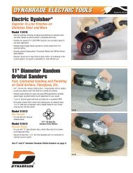
4 Hp/Straight Line/Rear Exhaust Die Grinder - Dynabrade Inc.
4 Hp/Straight Line/Rear Exhaust Die Grinder - Dynabrade Inc.
4 Hp/Straight Line/Rear Exhaust Die Grinder - Dynabrade Inc.

Create successful ePaper yourself
Turn your PDF publications into a flip-book with our unique Google optimized e-Paper software.
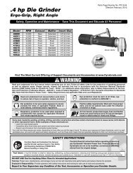
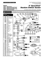
Disassembly/Assembly Instructions - .4 <strong>Hp</strong>/<strong>Straight</strong>-<strong>Line</strong>/<strong>Rear</strong> <strong>Exhaust</strong><br />
Important: Manufacturer’s warranty is void if tool is disassembled before warranty expires.<br />
Notice: <strong>Dynabrade</strong> strongly recommends the use of their 52296 Repair Collar (sold separately) during assembly/disassembly activities. Failure to<br />
use this collar will highly increase the risk of damage to the valve body of this tool. Please refer to parts breakdown for part identification.<br />
Motor Disassembly:<br />
1. Secure air tool in vise using 52296 Repair Collar or padded jaws.<br />
2. Remove collet cap and insert.<br />
3. With an adjustable pin wrench, remove 01489 <strong>Exhaust</strong> Cover by turning counter-clockwise. Remove muffler insert.<br />
4. Pull motor assembly from housing.<br />
5. Press rotor from 02696 <strong>Rear</strong> Bearing. Press 02696 Bearing from 02676 <strong>Rear</strong> Bearing Plate.<br />
6. Remove 01435 Collet Body from rotor shaft. Twist collet counter clockwise from shaft.<br />
7. Remove 02649 Front Bearing, bearing plate, cylinder, blades (4) and 01479 Spacer from rotor.<br />
Note: 02649 Bearing is a slip fit into 01478 Front Bearing Plate.<br />
Motor Disassembly Complete.<br />
Motor Assembly:<br />
Important: Be sure parts are clean and in good repair before assembling.<br />
1. Place 01475 Rotor in padded vise with threaded spindle facing upward.<br />
2. Slip 01479 Spacer onto rotor.<br />
3. Place a .002" shim into 01478 Front Bearing Plate as an initial spacing (Note: 54529 Shim Pack contains .001", .002", and .003" shims) and slip<br />
02649 Bearing into plate.<br />
4. Install bearing/bearing plate assembly onto rotor.<br />
5. Tighten 01435 Collet Body onto rotor (torque to 17 N•m/150 in. - lbs.).<br />
6. Check clearance between rotor and bearing plate by using a .001" feeler gauge. Clearance should be at .001" to .0015". Adjust clearance by repeating<br />
steps 1-5 with different shim if necessary.<br />
7. Once proper rotor/gap clearance is achieved, install well lubricated 01480 Blades (4) into rotor slots.<br />
<strong>Dynabrade</strong> Air Lube P/N 95842 is recommended for lubrication.<br />
8. Install cylinder over rotor.<br />
9. Press 02696 <strong>Rear</strong> Bearing into 02673 <strong>Rear</strong> Bearing Plate. Press bearing/bearing plate assembly onto rotor. Be sure that pin and air inlet holes<br />
line-up with pin slot and air inlet holes in cylinder. Important: Fit must be snug between bearing plates and cylinder. A loose fit will not achieve the<br />
proper pre-load of motor bearings. If too tight, rotor will not turn freely. Rotor must then be lightly tapped at press fit end so it will turn freely while still<br />
maintaining a snug fit.<br />
10. Secure housing in vise using 52296 Repair Collar.<br />
11. Place 02679 Shield over 02696 <strong>Rear</strong> Bearing and Install motor assembly into housing. Be sure motor fits all the way into housing.<br />
12. Assemble 01580 Silencer into 01489 <strong>Exhaust</strong> Cover and install onto motor housing (torque 28 N•m/250 in. - lbs.).<br />
13. Motor adjustment must now be checked. With motor housing still mounted in vise, pull end of rotor and twist (10-15 lbs. force), rotor should turn<br />
freely without drag. If drag or rub is felt, then increase preload or remove shim. Also, push end of rotor and twist (10-15 lbs. force), rotor should<br />
turn freely without drag. If drag or rub is felt, then deload or add shim.<br />
Motor Assembly Complete.<br />
Valve Body Disassembly:<br />
1. Position valve body in a vise by using 52296 Repair Collar so that air inlet points up.<br />
2. Secure 01578 Inlet Adapter with a wrench to prevent it from turning. While holding the inlet adapter stationary remove the air fitting by turning it<br />
counterclockwise. Important: 01578 Inlet Adapter must be secured before attempting to remove the air fitting so as to avoid damaging the valve body housing.<br />
3. Remove 01578 Inlet Adapter.<br />
4. Remove 95711 Retaining Ring from inlet adapter. Then remove 01486 Felt Silencer (4), and 01379 Bronze Muffler.<br />
5. Remove 01567 or 01564 Air Control Ring from the valve body housing. Use needle nose pliers and remove 01468 Spring, 01472 Tip Valve and 01464 Seal.<br />
6. Use a 2.5 drive punch to remove 12132 Pin and 01448 or 01462 Throttle Lever.<br />
7. Remove 95558 Retaining Ring and push 01469 Regulator from the valve body housing.<br />
Valve Body Disassembly Complete.<br />
Valve Body Assembly:<br />
1. Install 01469 Regulator complete with o-rings and valve stem into valve body housing. Secure it in place with 95558 Retaining Ring.<br />
2. Place valve body housing in a vise, holding it with the aid of 52296 Repair Collar so that the air inlet openings points up.<br />
3. Insert 01464 Seal into the air inlet opening so that it lays flat.<br />
4. <strong>Line</strong> up hole in valve stem with inlet opening in housing (looking past brass bushing). Install 01472 Tip Valve so that the metal pin passes through the<br />
hole in the valve stem. Install 01478 Spring (small end against tip valve).<br />
5. Position 01567 or 01564 Air Control Ring around inlet opening. Place 01379 Bronze Muffler inside 01446 Air Deflector.<br />
6. With 95620 Retaining Ring installed on female threaded end of 01578 Inlet Adapter insert the inlet adapter through 01446 Air Deflector.<br />
7. Place 01486 Felt Silencer (4) inside 01446 Air Deflector.<br />
(continued on next page)<br />
3