Sensorless Torque Estimation using Adaptive Kalman Filter and ...
Sensorless Torque Estimation using Adaptive Kalman Filter and ...
Sensorless Torque Estimation using Adaptive Kalman Filter and ...

Create successful ePaper yourself
Turn your PDF publications into a flip-book with our unique Google optimized e-Paper software.
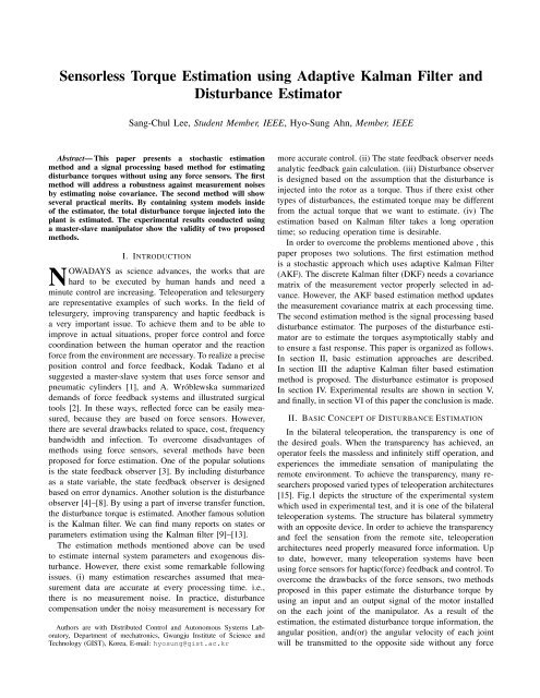
<strong>Sensorless</strong> <strong>Torque</strong> <strong>Estimation</strong> <strong>using</strong> <strong>Adaptive</strong> <strong>Kalman</strong> <strong>Filter</strong> <strong>and</strong><br />
Disturbance Estimator<br />
Sang-Chul Lee, Student Member, IEEE, Hyo-Sung Ahn, Member, IEEE<br />
Abstract— This paper presents a stochastic estimation<br />
method <strong>and</strong> a signal processing based method for estimating<br />
disturbance torques without <strong>using</strong> any force sensors. The first<br />
method will address a robustness against measurement noises<br />
by estimating noise covariance. The second method will show<br />
several practical merits. By containing system models inside<br />
of the estimator, the total disturbance torque injected into the<br />
plant is estimated. The experimental results conducted <strong>using</strong><br />
a master-slave manipulator show the validity of two proposed<br />
methods.<br />
I. INTRODUCTION<br />
NOWADAYS as science advances, the works that are<br />
hard to be executed by human h<strong>and</strong>s <strong>and</strong> need a<br />
minute control are increasing. Teleoperation <strong>and</strong> telesurgery<br />
are representative examples of such works. In the field of<br />
telesurgery, improving transparency <strong>and</strong> haptic feedback is<br />
a very important issue. To achieve them <strong>and</strong> to be able to<br />
improve in actual situations, proper force control <strong>and</strong> force<br />
coordination between the human operator <strong>and</strong> the reaction<br />
force from the environment are necessary. To realize a precise<br />
position control <strong>and</strong> force feedback, Kodak Tadano et al<br />
suggested a master-slave system that uses force sensor <strong>and</strong><br />
pneumatic cylinders [1], <strong>and</strong> A. Wróblewska summarized<br />
dem<strong>and</strong>s of force feedback systems <strong>and</strong> illustrated surgical<br />
tools [2]. In these ways, reflected force can be easily measured,<br />
because they are based on force sensors. However,<br />
there are several drawbacks related to space, cost, frequency<br />
b<strong>and</strong>width <strong>and</strong> infection. To overcome disadvantages of<br />
methods <strong>using</strong> force sensors, several methods have been<br />
proposed for force estimation. One of the popular solutions<br />
is the state feedback observer [3]. By including disturbance<br />
as a state variable, the state feedback observer is designed<br />
based on error dynamics. Another solution is the disturbance<br />
observer [4]–[8]. By <strong>using</strong> a part of inverse transfer function,<br />
the disturbance torque is estimated. Another famous solution<br />
is the <strong>Kalman</strong> filter. We can find many reports on states or<br />
parameters estimation <strong>using</strong> the <strong>Kalman</strong> filter [9]–[13].<br />
The estimation methods mentioned above can be used<br />
to estimate internal system parameters <strong>and</strong> exogenous disturbance.<br />
However, there exist some remarkable following<br />
issues. (i) many estimation researches assumed that measurement<br />
data are accurate at every processing time. i.e.,<br />
there is no measurement noise. In practice, disturbance<br />
compensation under the noisy measurement is necessary for<br />
Authors are with Distributed Control <strong>and</strong> Autonomous Systems Laboratory,<br />
Department of mechatronics, Gwangju Institute of Science <strong>and</strong><br />
Technology (GIST), Korea, E-mail: hyosung@gist.ac.kr<br />
more accurate control. (ii) The state feedback observer needs<br />
analytic feedback gain calculation. (iii) Disturbance observer<br />
is designed based on the assumption that the disturbance is<br />
injected into the rotor as a torque. Thus if there exist other<br />
types of disturbances, the estimated torque may be different<br />
from the actual torque that we want to estimate. (iv) The<br />
estimation based on <strong>Kalman</strong> filter takes a long operation<br />
time; so reducing operation time is desirable.<br />
In order to overcome the problems mentioned above , this<br />
paper proposes two solutions. The first estimation method<br />
is a stochastic approach which uses adaptive <strong>Kalman</strong> <strong>Filter</strong><br />
(AKF). The discrete <strong>Kalman</strong> filter (DKF) needs a covariance<br />
matrix of the measurement vector properly selected in advance.<br />
However, the AKF based estimation method updates<br />
the measurement covariance matrix at each processing time.<br />
The second estimation method is the signal processing based<br />
disturbance estimator. The purposes of the disturbance estimator<br />
are to estimate the torques asymptotically stably <strong>and</strong><br />
to ensure a fast response. This paper is organized as follows.<br />
In section II, basic estimation approaches are described.<br />
In section III the adaptive <strong>Kalman</strong> filter based estimation<br />
method is proposed. The disturbance estimator is proposed<br />
In section IV. Experimental results are shown in section V,<br />
<strong>and</strong> finally, in section VI of this paper the conclusion is made.<br />
II. BASIC CONCEPT OF DISTURBANCE ESTIMATION<br />
In the bilateral teleoperation, the transparency is one of<br />
the desired goals. When the transparency has achieved, an<br />
operator feels the massless <strong>and</strong> infinitely stiff operation, <strong>and</strong><br />
experiences the immediate sensation of manipulating the<br />
remote environment. To achieve the transparency, many researchers<br />
proposed varied types of teleoperation architectures<br />
[15]. Fig.1 depicts the structure of the experimental system<br />
which used in experimental test, <strong>and</strong> it is one of the bilateral<br />
teleoperation systems. The structure has bilateral symmetry<br />
with an opposite device. In order to achieve the transparency<br />
<strong>and</strong> feel the sensation from the remote site, teleoperation<br />
architectures need properly measured force information. Up<br />
to date, however, many teleoperation systems have been<br />
<strong>using</strong> force sensors for haptic(force) feedback <strong>and</strong> control. To<br />
overcome the drawbacks of the force sensors, two methods<br />
proposed in this paper estimate the disturbance torque by<br />
<strong>using</strong> an input <strong>and</strong> an output signal of the motor installed<br />
on the each joint of the manipulator. As a result of the<br />
estimation, the estimated disturbance torque information, the<br />
angular position, <strong>and</strong>(or) the angular velocity of each joint<br />
will be transmitted to the opposite side without any force
Fig. 1.<br />
Structure of the teleoperation system<br />
sensors (see Fig.1). Thus, control designers will be able to<br />
apply many teleoperation architectures <strong>and</strong> their own control<br />
strategies with the haptic(force) feedback.<br />
A. System model<br />
III. ADAPTIVE KALMAN FILTER BASED<br />
DISTURBANCE ESTIMATION<br />
In this section, we treat the disturbance estimation <strong>using</strong><br />
noisy measurement. A linear stochastic model of a DC motor<br />
used for the stochastic approach is represented as follows:<br />
ẋ(t) = F x(t) + Bu(t) (1)<br />
y(t) = Hx(t) + v(t) (2)<br />
where the matrix F ∈ R n×n represents the system matrix<br />
<strong>and</strong> the matrix B ∈ R p×p represents the control input matrix.<br />
The matrix H ∈ R m×n is the output matrix, <strong>and</strong> v ∈ R m is<br />
the measurement noise vector. By <strong>using</strong> an equivalent block<br />
diagram of the DC motor as depicted in Fig.2, the linear<br />
stochastic model is obtained as follows:<br />
ẋ 1 = x 2<br />
ẋ 2 = − B J x 2 + K J I − 1 J D in (3)<br />
y = x 1 + v<br />
where B, K, J, I, <strong>and</strong> D in denote viscous coefficient, torque<br />
constant, moment of inertia, control signal(armature current),<br />
<strong>and</strong> the disturbance torque, respectively. Noting that x =<br />
[ θ ω<br />
] T<br />
, we obtain the vector matrix form of the linear<br />
stochastic model.<br />
[ ˙θ<br />
˙ω<br />
] [ 0 1<br />
=<br />
0 − B J<br />
] [ θ<br />
ω<br />
]<br />
+<br />
[ 0<br />
K<br />
J<br />
] [ 0<br />
I +<br />
− 1 J<br />
]<br />
D in<br />
(4)<br />
I<br />
K<br />
<br />
<br />
Fig. 2.<br />
D in<br />
1<br />
J<br />
motor<br />
B<br />
J<br />
<br />
1<br />
1<br />
s s<br />
Block diagram of a DC motor<br />
where θ, <strong>and</strong> ω represent angular position(x 1 ), <strong>and</strong> angular<br />
velocity(x 2 ), respectively. Equation (4) shows the disturbance<br />
torque(D in ) is acting as a second input. We assume the<br />
disturbance torque(D in ) is independent to the state variables<br />
<strong>and</strong> unbounded. Based on the additional assumptions that<br />
the characteristic of the disturbance is nearly constant <strong>and</strong><br />
sampling speed is fast enough, the disturbance is included<br />
in the system model as a state variable. By integrating the<br />
disturbance into the system model(4), <strong>and</strong> discretization, the<br />
extended model obtained as follows :<br />
⎡<br />
⎤ ⎛ ⎡<br />
⎤⎞<br />
⎡<br />
θ(k + 1)<br />
0 1 0<br />
⎣ ω(k + 1) ⎦ = ⎝I + T s<br />
⎣ 0 − B J<br />
− 1 ⎦⎠<br />
J<br />
D in (k + 1)<br />
0 0 0<br />
⎡ ⎤<br />
0<br />
+ T S<br />
⎣ K ⎦ I(k)<br />
J<br />
0<br />
⎡<br />
y(k) = [ 1 0 0 ] ⎣<br />
θ(k)<br />
ω(k)<br />
D in (k)<br />
⎤<br />
<br />
⎣ θ(k)<br />
ω(k)<br />
D in (k)<br />
⎤<br />
⎦<br />
(5)<br />
⎦ + v(k) (6)<br />
where T S represent the sampling time. We assume<br />
the measurement noise(v(k)) is the zero mean gaussian<br />
noise(v(k)˜N(0, R k )). The following AKF based disturbance<br />
observer estimates D in by the extended model (5-6).
B. AKF based disturbance observer<br />
In the extended system model (5-6), as the pair of the<br />
system matrix <strong>and</strong> the output matrix is observable, full<br />
order estimation is guaranteed by the DKF. Even the DKF<br />
guarantees the full order estimation, in order to yield the best<br />
result, the DKF needs an accurately selected measurement<br />
covariance matrix in advance. However, obtaining the<br />
accurate covariance matrix is not easy. Moreover, the<br />
measurement covariance matrix can be changed with time.<br />
To overcome the problems mentioned above, this paper<br />
suggests the AKF based disturbance observer. For an LTI<br />
system, the recursive algorithm of the AKF is described as<br />
follows [14], [16]:<br />
Time update<br />
1 ) Project the state ahead<br />
ˆx k|k+1 = F k−1ˆx k−1|k−1 + B k u k (7)<br />
2 ) Project the error covariance ahead<br />
Measurement update<br />
1) <strong>Kalman</strong> gain<br />
P k|k+1 = K k P k−1|k−1 F k T + Q ∗ k (8)<br />
K k = P k|k−1 H T k (H k P k|k−1 H T k + ˆR ∗ k) −1 (9)<br />
2) Update estimate with measurement Z k<br />
ˆx k|k = ˆx k|k−1 + K k (z k − H k ˆx k|k−1 ) (10)<br />
3) Update the error covariance<br />
P k|k = (I − K k H k )P k|k−1 (11)<br />
where F ∈ R n×n , B ∈ R n×n , K ∈ R n×m , <strong>and</strong> P ∈ R n×n<br />
represent the system matrix, the input matrix,the kalman<br />
gain, <strong>and</strong> the covariance state matrix, respectively. H ∈<br />
R m×n , Q ∈ R n , <strong>and</strong> z k ∈ R m denote the output vector,<br />
the covariance vector of system noise, <strong>and</strong> measurement,<br />
respectively. The AKF based disturbance observer is different<br />
to the DKF in terms of an adaptive covariance matrix<br />
ˆR<br />
k ∗ ∈ Rm×m in (9). The covariance matrix is updated by<br />
a covariance uncertainties online estimator represented as<br />
follows [16]:<br />
ˆR ∗ (k i ) = 1 i∑<br />
{[z j − H(k j )ˆx(k<br />
N<br />
j )][z j − H(k j )ˆx(k j )] T<br />
j=i−N+1<br />
+ H(k j )P (k j )H T (k j )}<br />
(12)<br />
The first term in the bracket represents a squared error<br />
matrix between the measurements <strong>and</strong> the estimated states,<br />
<strong>and</strong> diagonal elements of the second term are the covariances<br />
of state variables. In the first term, the noisy(clear) measurement<br />
makes the big(small) squared error term. Thus, ˆR∗ k<br />
is<br />
increased(decreased), <strong>and</strong> it decreases(increases) the <strong>Kalman</strong><br />
gain K k . Consequently, the dependence of the estimation<br />
result between previously estimated states <strong>and</strong> current measurement<br />
will be affected by the quality of measurement. As<br />
we can see in (12), the covariance uncertainties estimator<br />
needs N number of recent measurements. By an average of<br />
the recent N number of terms in the bracket, the AKF based<br />
disturbance observer updates the measurement covariance<br />
matrix ˆR k ∗ at each processing time. In addition, large number<br />
of the measurement will offer a more accurate measurement<br />
covariance matrix( ˆR k ∗) estimation.<br />
A. System model<br />
IV. DISTURBANCE ESTIMATOR<br />
This section proposes a signal processing based estimation<br />
method. For the estimation, the DC motor model is used (see<br />
Fig.2). In Fig.3, the upper part describes the system model,<br />
<strong>and</strong> the middle <strong>and</strong> lower part represent the disturbance<br />
estimator. In the system model, an input disturbance D input<br />
<strong>and</strong> an output disturbance D output are described. The input<br />
disturbance D input can be any kind of disturbance, e.g., load<br />
force(torque), gravitational torque, parametric fluctuation or<br />
any combinations of them. In order to validate the total<br />
disturbance estimation, D output is injected. We assume the<br />
disturbances are independent to the system <strong>and</strong> unbounded.<br />
Subscript n denotes the nominal value of parameters.<br />
B. Disturbance estimator<br />
The disturbance estimator consists of an extraction part<br />
<strong>and</strong> an estimation part. The two parts are cascade-connected.<br />
As a first step, the extraction part calculates the system<br />
output generated by the input <strong>and</strong> output disturbances. After<br />
that, the estimation part generates the final estimation result.<br />
Each process is described as follows:<br />
1) Extraction part:<br />
The composition of the extraction part is same to the<br />
system model, but it does not have any disturbances. The<br />
computation of the extraction part is described as follows:<br />
(<br />
K<br />
θ D = −<br />
s(Js + B) I + 1<br />
s(Js + B) D input + 1 )<br />
s D output<br />
(<br />
)<br />
K n<br />
+<br />
s(J n s + B n ) I<br />
(13)<br />
The term in the upper bracket represents the actual<br />
position result(θ I,D ) generated by the control input(I)<br />
<strong>and</strong> both the input disturbance(D input ) <strong>and</strong> the output<br />
disturbance(D output ). The term in the lower bracket<br />
shows the position result((θ I ) generated by the control<br />
input(I) only. Due to the subtraction, where the parameters<br />
K, J, <strong>and</strong>B are same with K n , J n , <strong>and</strong>B n , the output of<br />
the extraction part(θ D ) is the angular position generated<br />
by the disturbances only. Otherwise, the output contains<br />
contain the angular position generated by the parametric<br />
fluctuation(uncertainty) also. It implies all the dynamics<br />
not considered in extraction part are considered as the
I<br />
motor<br />
K<br />
<br />
<br />
T<br />
D input<br />
1<br />
J<br />
<br />
B<br />
J<br />
<br />
D output<br />
1 1<br />
s I , D s<br />
law is applied:<br />
u = K P e + K I<br />
∫<br />
edτ + K D<br />
de<br />
dt<br />
(16)<br />
The PID control law(15) together with ė 0 = e 1 <strong>and</strong> error<br />
equations (14), error dynamics described as follows:<br />
D<br />
<br />
<br />
disturbance.<br />
K n<br />
Fig. 3.<br />
PID<br />
1<br />
J n<br />
u D<br />
u<br />
ˆ<br />
total<br />
<br />
B<br />
J<br />
n<br />
n<br />
1<br />
1<br />
s I s<br />
1<br />
J n<br />
B<br />
J<br />
n<br />
n<br />
Extraction<br />
<br />
1<br />
1<br />
s *<br />
<br />
s<br />
I<br />
I , D<br />
<br />
<br />
<strong>Estimation</strong><br />
*<br />
D<br />
Disturbance Estimator<br />
Block diagram of motor with disturbance<br />
2) <strong>Estimation</strong> part:<br />
The estimation part calculates the final estimation result<br />
by <strong>using</strong> a control loop. The reference signal of the control<br />
loop is output of the extraction part(θ D ). Except the torque<br />
coefficient(K n ) of the extraction part <strong>and</strong> a PID controller<br />
of the estimation part, the open-loop transfer functions are<br />
exactly same. If the estimation part is stable, the feedback<br />
signal(θ ∗ D ) follows the reference(θ D), <strong>and</strong> the output of<br />
the PID controller approaches the total disturbance. Consequently,<br />
designing the disturbance estimator is concluded by<br />
making the estimation part asymptotically stable. In order to<br />
obtain a stable region of the PID gains, state space equations<br />
is used. Except the PID controller, the open-loop dynamics<br />
of the estimation part is described as follows:<br />
ẋ 1 = x 2<br />
ẋ 2 = − B n<br />
x 2 + 1 u (14)<br />
J n J n<br />
y = x 1<br />
where x = [ θ ∗ D ω∗ ] T<br />
. In order to determine error<br />
equations, let e = θ D − θ ∗ D = θ D − x 1 = e 1 . Then error<br />
equations obtained as follows:<br />
ė 1 = −ẋ 1 = e 2<br />
ė 2 = B n<br />
x 2 − 1 u (15)<br />
J n J n<br />
To determine the control signal(u) in (14), the PID control<br />
ė 0 = e 1<br />
ė 1 = e 2 (17)<br />
( ) ( ) ( )<br />
KI KP Bn<br />
ė 2 = − e 0 − e 1 − + K D e 2<br />
J n J n J n<br />
If the characteristic matrix of the error dynamics is Hurwitz,<br />
error approaches zero asymptotically. It indicates θD ∗ <strong>and</strong> u<br />
also asymptotically approach θ D <strong>and</strong> the total disturbance<br />
D total , respectively. In order to calculate stable region of<br />
the PID gains, Routh−Hurwitz theorem is used. Calculated<br />
region of the PID gains are written as follows :<br />
K I<br />
J n<br />
> 0 ,<br />
K P<br />
J n<br />
> 0 ,<br />
B n<br />
J n<br />
+ K D > 0 (18)<br />
As we mentioned above, the estimated total disturbance<br />
contains not only exogenous disturbances(D input <strong>and</strong><br />
D output ) but also all the discordance between the real<br />
system model <strong>and</strong> the model of the extraction part. In<br />
addition, simply removing all the viscous friction loops in<br />
Fig.3, the viscous friction also estimated as the disturbance.<br />
It shows the flexibility of the disturbance estimator.<br />
V. EXPERIMENTAL RESULTS<br />
To validate proposed two estimation methods, experimental<br />
tests were conducted <strong>using</strong> a master-slave system. The<br />
overall setup is shown in Fig.4, <strong>and</strong> the specifications of<br />
motor drivers <strong>and</strong> motors are shown in Tables I <strong>and</strong> II. For<br />
the tests, the slave manipulator was fixed, <strong>and</strong> the operator<br />
manipulated the master to give an order to the slave device.<br />
A. AKF based disturbance observer<br />
The experimental test of the AKF based estimation<br />
method is conducted by two ways. At the first, we confirmed<br />
the improvement of the AKF based method in comparison<br />
with the DKF. In order to obtain noisy measurement, same<br />
zero mean gaussian noise having 0.5 of the st<strong>and</strong>ard deviation<br />
is added to the measurements of both the AFK <strong>and</strong> DKF.<br />
In addition, wrong measurement covariance (R k = 0.2 2 )<br />
is given to the DKF. Due to the manipulator is fixed, the<br />
mean of the measurement is ideally zero. Fig.5 shows the<br />
measurements, i.e., control signal(I) of the slave motor,<br />
<strong>and</strong> the position discordance between the master <strong>and</strong> slave<br />
manipulators. The AKF based observer also tested under the<br />
same condition. We set the wrong measurement covariance<br />
as (0.2 2 ), <strong>and</strong> we set the accumulation number(N) in (12)<br />
as 5. The estimation results of the DKF <strong>and</strong> AKF based<br />
observer are shown in Fig.6. Due to the DKF dose not<br />
have the measurement covariance adaptation algorithm, the
Fig. 5.<br />
Measured armature current <strong>and</strong> Position difference(DKF)<br />
Fig. 4.<br />
Experimental setup : master-slave manipulator<br />
TABLE I<br />
SPECIFICATION OF MOTOR DRIVERS<br />
Output voltage<br />
Output current<br />
Maxon - ADS 50/5<br />
VCC min. 12 VDC; max. 50VDC<br />
Depending on load, continuous 5A<br />
<br />
<br />
Fig. 6. Disturbance estimation. (a) DKF, (b) AKF (N=5).<br />
TABLE II<br />
SPECIFICATION OF MOTORS<br />
Maxon - RE30<br />
Assigned power rating(W) 60<br />
Max. continuous current(A) 4<br />
<strong>Torque</strong> constant(mNm / A) 25.9<br />
Max. continuous torque(mNm) 86.2<br />
<br />
<br />
estimation is based on the given wrong measurement covariance<br />
matrix. As the Fig.6(a) demonstrates, the estimation<br />
result of the DKF containing a lot of noise. If it used for<br />
the haptic feedback <strong>and</strong> the position control, it will make<br />
huge vibration on the manipulator. On the other h<strong>and</strong>, even<br />
the given initial measurement covariance matrix of the AKF<br />
was mismatched to the actual noise, the AKF calculated<br />
relatively clear estimation result(see Fig.6(b)) based on the<br />
covariance uncertainties online estimator(12). Such result<br />
demonstrates the AKF based disturbance observer corrects<br />
the measurement covariance matrix at each processing time.<br />
Moreover, such result indicates possibility of the reliable<br />
estimation under the noisy circumstance. As the second test,<br />
we applied huge number(R k = 1 2 ) of the st<strong>and</strong>ard deviation<br />
to the measurement noise. Fig.7(a) shows the estimation<br />
result when the number of accumulation(N) is 5. On the<br />
other h<strong>and</strong>, when we used 30 number of measurement data,<br />
as shown in Fig.7(b) significantly improved estimation result<br />
is obtained. As depicted above, the disturbance estimation<br />
<strong>using</strong> noisy measurement is achieved.<br />
B. Disturbance Estimator<br />
This subsection validate the disturbance estimator. For<br />
the test, same bilateral teleoperation system is used. Two<br />
Fig. 7. Disturbance estimation <strong>using</strong> different number of measurement<br />
accumulation (AKF), st<strong>and</strong>ard deviation = 1<br />
measurements of the disturbance estimator, the control<br />
signal <strong>and</strong> the angular position of the slave manipulator<br />
are depicted in Fig.8. From the two measurements,<br />
extraction part calculates the position(θ D ) by <strong>using</strong> (13),<br />
<strong>and</strong> then estimation part calculates the total disturbance. In<br />
the experimental test, PID gains K P = 0.135, K I = 0.01,<br />
K D = 0.008 are used to make estimation part asymptotically<br />
stable. We can find that a set of PID gains satisfies condition<br />
(17) in the continuous time domain. Of course PID gains<br />
can be selected by trial <strong>and</strong> error also. In Fig.9(a), the<br />
output of the extraction part(θ D : reference of the estimation<br />
part) is denoted as reference, <strong>and</strong> the feedback signal of<br />
the estimation part(θD ∗ ) is represented as tracking. Tracking<br />
performance can be used as an estimation performance index<br />
in real time. The total estimation result is shown in Fig.9(b).<br />
In the test, the angular position is used for the measurement<br />
of the disturbance estimator, however, even the designer<br />
uses the angular velocity as the measurement but not<br />
position, disturbance estimator will precisely estimate the<br />
total disturbance just by eliminating the last one integrator at<br />
each extraction <strong>and</strong> estimation part. It shows the flexibility
plant model as its sub-model. In addition, we used a PID<br />
controller for the disturbance estimation. However, any kind<br />
of controller <strong>and</strong> control technique can be used which can<br />
make the estimator stable.<br />
<br />
Fig. 8.<br />
<br />
Fig. 9.<br />
<br />
Measurement (Disturbance Estimator)<br />
<br />
<strong>Estimation</strong> result of the disturbance estimator<br />
of the disturbance estimator again.<br />
VI. CONCLUSIONS<br />
This paper proposed a stochastic estimation method <strong>and</strong><br />
a signal processing based method for the purpose of disturbance<br />
torque estimation without force sensors. The AKF<br />
based method presented robustness against the measurement<br />
noise. When the measurements have a lot of noise, <strong>and</strong> its<br />
characteristic is unknown, this method can be one of the<br />
reliable methods.<br />
Through the section IV <strong>and</strong> V, we proposed several merits<br />
of the disturbance estimator, <strong>and</strong> they can be summarized<br />
as follows: (i) Wherever the disturbance injected between<br />
two measurements(I <strong>and</strong> θ I,D ), the disturbance estimator<br />
estimates the total disturbance as asymptotically stable. (ii)<br />
The disturbance estimator inherits the structure of the system<br />
model. Thus it provide the instinctive <strong>and</strong> direct application.<br />
(iii) Unrestricted selection of the measurement type is possible.<br />
(iv) We can determine the types of disturbance included<br />
in the total disturbance by considering sub-model of the<br />
disturbance estimator. In addition to the merits mentioned<br />
above, when the disturbance estimator used for feedback<br />
compensation, the disturbance estimator will try to make<br />
the system act as same with the sub-model. Because all<br />
the effects not considered in the sub-model is estimated<br />
as the disturbance. In consequence, direct <strong>and</strong> fast loop<br />
shaping could be achieved. Feedback control, loop shaping<br />
<strong>and</strong> extending to the nonlinear disturbance estimator are our<br />
future works. In this paper, a DC motor model is used<br />
for total disturbance estimation. However, the disturbance<br />
estimator can be used in countless system simply having the<br />
ACKNOWLEDGEMENT<br />
This research was supported by the institute of Medical<br />
System Engineering(iMSE) in the GIST, <strong>and</strong> by the<br />
MKE(The Ministry of Knowledge Economy), Korea, under<br />
the ITRC(Information Technology Research Center) support<br />
program supervised by the NIPA(National IT Industry Promotion<br />
Agency) (NIPA-2010-C1090-1031-0006)<br />
REFERENCES<br />
[1] Tadano K <strong>and</strong> Kawashima K, Development of a Master Slave System<br />
with Force Sensing Using Pneumatic Servo System for Laparoscopic<br />
Surgery, IEEE Int. Con. on Robotics <strong>and</strong> Automation, pp. 947 - 952,<br />
2007.<br />
[2] A. Wróblewska, Methods of the force measurement for robotic surgical<br />
tools, Proc. the Fifth International Workshop on, Robot Motion <strong>and</strong><br />
Control, pp. 51 - 54, 2005.<br />
[3] Giuseppe S. Buja, Disturbance torque estimation in a sensorless DC<br />
drive, Proc. IECON. Int. Conference on Industrial Electronics, Control,<br />
<strong>and</strong> Instrumentation., vol.2, pp. 977 - 982, 1993.<br />
[4] Satoshi Komada, Muneaki Ishidar, Kouhei Ohnishi, <strong>and</strong> Takamasa<br />
Hori, Disturbance Observer Based Motion Control of Direct Drive<br />
Motors, IEEE Transaction on Energy Conversion, vol.6, Issue.3, pp.<br />
553 - 559, 1991.<br />
[5] Kenji Kaneko, Kiyoshi Komoria, Kouhei Ohnishi <strong>and</strong> Kazuo Tanie,<br />
Manipulator Control based on a Disturbance Observer in the Operational<br />
Space, Proc. IEEE Int. Conf. on Robotics <strong>and</strong> Automation, 1994,<br />
vol.2, pp. 902 - 909, 1994.<br />
[6] Liu C.S. <strong>and</strong> Peng H, Disturbance observer based tracking control,<br />
Journal of Dynamic Systems, Measurement, <strong>and</strong> Control, vol.122,<br />
Issue.2, pp. 332 - 335, 2000.<br />
[7] Satoshi Komadar, Muneaki Ishidar, Kouhei Ohnishiir <strong>and</strong> Takamasa<br />
Horii, Motion control of linear synchronous motors based on disturbance<br />
observer, 16th Annual Conference of IEEE Industrial Electronics<br />
Society, 1990. IECON ’90., vol.1, pp. 154 - 159 , 1990.<br />
[8] Edi Leksono, Toshiyuki Murakami <strong>and</strong> Kouhei Ohnishi, Observer<br />
Based Robust Force Control in cooperative Motion Systems, Proc. the<br />
24th Annual Conf. of the IEEE Industrial Electronics Society, IECON<br />
’98., vol.3, pp. 1801 - 1806, 1998.<br />
[9] P.P.AcarnIey, J.K.AI-Tayie, <strong>Estimation</strong> of speed <strong>and</strong> armature temperature<br />
in a brushed DC drive <strong>using</strong> the extended <strong>Kalman</strong> filter, Proc.<br />
IEE Electric Power Applications, vol.144, Issue.1, pp. 13 - 20, 1997.<br />
[10] Zhengyun Ran, Huade Li, <strong>and</strong> Shujin Chen, Application of Optimized<br />
EKF in Direct <strong>Torque</strong> Control System of induction motor, Int. Con. on<br />
Innovative Computing, Information <strong>and</strong> Control, ICICIC ’06., vol.1,<br />
pp. 331 - 335, 2006.<br />
[11] Murat Barut, Seta Bogosyan <strong>and</strong> Metin Gokasan, EKF Based <strong>Sensorless</strong><br />
Direct <strong>Torque</strong> Control of IMs in the Low Speed Range, Proc. the<br />
IEEE International Symposium on Industrial Electronics, ISIE 2005.,<br />
vol.3, pp. 969 - 974, 2005.<br />
[12] Yong Liu, Zi Qiang Zhu <strong>and</strong> David Howe, Instantaneous <strong>Torque</strong> <strong>Estimation</strong><br />
in <strong>Sensorless</strong> Direct-<strong>Torque</strong>-Controlled Brushless DC Motors,<br />
IEEE Transactions on Industry Applications., vol.42, Issue.5, pp. 1275<br />
- 1283, 2006.<br />
[13] Jing-Ping Jiang, Shen Chen <strong>and</strong> Pradip K.Sinha, Optimal Feedback<br />
Control of Direct-Current Motors, IEEE Transactions on Industrial<br />
Electronics., vol.37, Issue.4, pp. 269 - 274, 1990.<br />
[14] Jung-Han Kim <strong>and</strong> Jun-Ho Oh, Disturbance <strong>Estimation</strong> <strong>using</strong> Sliding<br />
Mode for Discrete <strong>Kalman</strong> <strong>Filter</strong>, Proc. the 37th IEEE Conference on<br />
Decision <strong>and</strong> Control., vol.2, pp. 1918 - 1919. 1998.<br />
[15] Edvard Naerum <strong>and</strong> Blake Hannaford, Global Transparency Analysis<br />
of the Lawrence Teleoperator Architecture,<br />
[16] Richard Bellman, Stochastic models, estimation. <strong>and</strong> control Vol.2,<br />
1994.