Industrial Control Power Transformers - C & E Sales, Inc.
Industrial Control Power Transformers - C & E Sales, Inc.
Industrial Control Power Transformers - C & E Sales, Inc.

You also want an ePaper? Increase the reach of your titles
YUMPU automatically turns print PDFs into web optimized ePapers that Google loves.
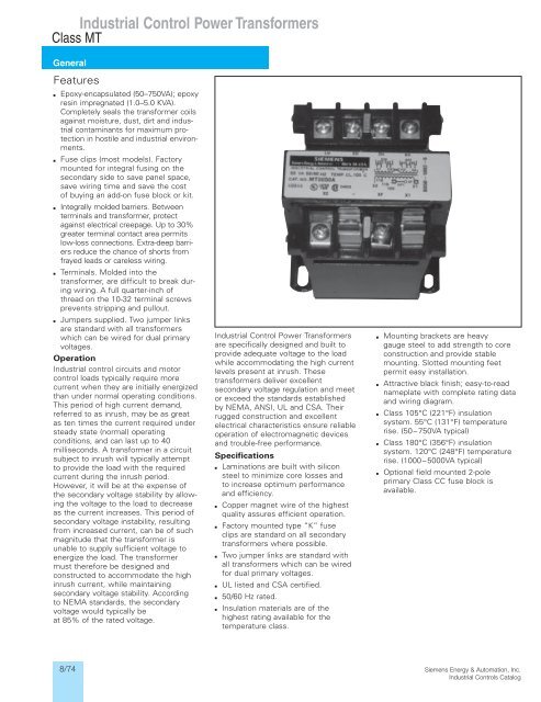
<strong>Industrial</strong> <strong>Control</strong> <strong>Power</strong> <strong>Transformers</strong><br />
Class MT<br />
General<br />
Features<br />
▪ Epoxy-encapsulated (50–750VA); epoxy<br />
resin impregnated (1.0–5.0 KVA).<br />
Completely seals the transformer coils<br />
against moisture, dust, dirt and industrial<br />
contaminants for maximum protection<br />
in hostile and industrial environments.<br />
▪ Fuse clips (most models). Factory<br />
mounted for integral fusing on the<br />
secondary side to save panel space,<br />
save wiring time and save the cost<br />
of buying an add-on fuse block or kit.<br />
▪ Integrally molded barriers. Between<br />
terminals and transformer, protect<br />
against electrical creepage. Up to 30%<br />
greater terminal contact area permits<br />
low-loss connections. Extra-deep barriers<br />
reduce the chance of shorts from<br />
frayed leads or careless wiring.<br />
▪ Terminals. Molded into the<br />
transformer, are difficult to break during<br />
wiring. A full quarter-inch of<br />
thread on the 10-32 terminal screws<br />
prevents stripping and pullout.<br />
▪ Jumpers supplied. Two jumper links<br />
are standard with all transformers<br />
which can be wired for dual primary<br />
voltages.<br />
Operation<br />
<strong>Industrial</strong> control circuits and motor<br />
control loads typically require more<br />
current when they are initially energized<br />
than under normal operating conditions.<br />
This period of high current demand,<br />
referred to as inrush, may be as great<br />
as ten times the current required under<br />
steady state (normal) operating<br />
conditions, and can last up to 40<br />
milliseconds. A transformer in a circuit<br />
subject to inrush will typically attempt<br />
to provide the load with the required<br />
current during the inrush period.<br />
However, it will be at the expense of<br />
the secondary voltage stability by allowing<br />
the voltage to the load to decrease<br />
as the current increases. This period of<br />
secondary voltage instability, resulting<br />
from increased current, can be of such<br />
magnitude that the transformer is<br />
unable to supply sufficient voltage to<br />
energize the load. The transformer<br />
must therefore be designed and<br />
constructed to accommodate the high<br />
inrush current, while maintaining<br />
secondary voltage stability. According<br />
to NEMA standards, the secondary<br />
voltage would typically be<br />
at 85% of the rated voltage.<br />
<strong>Industrial</strong> <strong>Control</strong> <strong>Power</strong> <strong>Transformers</strong><br />
are specifically designed and built to<br />
provide adequate voltage to the load<br />
while accommodating the high current<br />
levels present at inrush. These<br />
transformers deliver excellent<br />
secondary voltage regulation and meet<br />
or exceed the standards established<br />
by NEMA, ANSI, UL and CSA. Their<br />
rugged construction and excellent<br />
electrical characteristics ensure reliable<br />
operation of electromagnetic devices<br />
and trouble-free performance.<br />
Specifications<br />
▪ Laminations are built with silicon<br />
steel to minimize core losses and<br />
to increase optimum performance<br />
and efficiency.<br />
▪ Copper magnet wire of the highest<br />
quality assures efficient operation.<br />
▪ Factory mounted type “K” fuse<br />
clips are standard on all secondary<br />
transformers where possible.<br />
▪ Two jumper links are standard with<br />
all transformers which can be wired<br />
for dual primary voltages.<br />
▪ UL listed and CSA certified.<br />
▪ 50/60 Hz rated.<br />
▪ Insulation materials are of the<br />
highest rating available for the<br />
temperature class.<br />
▪ Mounting brackets are heavy<br />
gauge steel to add strength to core<br />
construction and provide stable<br />
mounting. Slotted mounting feet<br />
permit easy installation.<br />
▪ Attractive black finish; easy-to-read<br />
nameplate with complete rating data<br />
and wiring diagram.<br />
▪ Class 105°C (221°F) insulation<br />
system. 55°C (131°F) temperature<br />
rise. (50–750VA typical)<br />
▪ Class 180°C (356°F) insulation<br />
system. 120°C (248°F) temperature<br />
rise. (1000–5000VA typical)<br />
▪ Optional field mounted 2-pole<br />
primary Class CC fuse block is<br />
available.<br />
8/74<br />
Siemens Energy & Automation, <strong>Inc</strong>.<br />
<strong>Industrial</strong> <strong>Control</strong>s Catalog
<strong>Industrial</strong> <strong>Control</strong> <strong>Power</strong> <strong>Transformers</strong><br />
Class MTG<br />
General<br />
Features<br />
▪ Class MTG <strong>Industrial</strong> <strong>Control</strong> <strong>Transformers</strong> are 100%<br />
certified for all domestic and International Applications.<br />
▪ The MTG line has full compliance with IEC Safety<br />
standards EN 61 558.<br />
▪ CE Mark in accordance with requirements for EN 61 558.<br />
▪ Meets IP-20 specifications per IEC 529 for finger-safe<br />
protection when used with Siemens Touch Safe snap<br />
on terminal cover kits. Meets IP-00 specifications when<br />
covers are not used.<br />
▪ UL Listed (File # E46323)<br />
▪ CSA Certified (File #LR27533)<br />
▪ Exceeds applicable requirements for control transformers as<br />
determined by NEMA and ANSI.<br />
▪ Insulation requirements is twice that of UL506.<br />
▪ Proven Epoxy-encapsulated coils operate cooler and<br />
completely seal the transformer coils against moisture,<br />
dust, dirt and industrial contaminants for maximum<br />
protection in hostile and industrial environments.<br />
▪ Available in 50 to 750 VA sizes, in all standard voltage<br />
combinations.<br />
▪ Class 105°C (221°F) insulation system. 55°C (131°F)<br />
temperature rise. (50–750VA typical)<br />
▪ Class 180°C (356°F) insulation system. 120°C (248°F)<br />
temperature rise. (1000–5000VA typical)<br />
▪ Primary and secondary fusing capability available as field<br />
installed kits for domestic or international fusing.<br />
▪ Integrally-molded terminals and barriers between terminals<br />
make breakage virtually impossible during wiring. The MTG<br />
transformer construction is the same as our High Quality<br />
Class MT transformers.<br />
Optional Field Installed Fuse Clip Kits For Panel Mounting<br />
▪ 2-Pole primary Class CC fuse block<br />
▪ 1-Pole secondary midget fuse block for 13 ⁄32 1 1 ⁄2 fuses<br />
▪ 2-Pole primary international type fuse blocks<br />
▪ 1-Pole secondary international type fuse blocks<br />
Optional Touch-Safe Snap-On Terminal Cover Kits<br />
The Touch-Safe terminal covers are designed to comply<br />
with IEC 742 and IP 20 requirements. When installed,<br />
the covers prevent contact with current carrying parts on<br />
the transformer and are available for 4 terminal configurations.<br />
The international fuse block kits have inherent touch<br />
safe terminals and fuse clips.<br />
Siemens Meets International Standards<br />
CSA (Canadian Standards Association) was utilized as a<br />
Competent Body in reviewing, interpreting and properly<br />
complying with the requirements of IEC-742 to place a CE<br />
mark on its MTG Series product. As a National Certification<br />
Body, CSA also has the proper documentation and reports<br />
on file for MTG Series to utilize the CB Scheme ensuring<br />
acceptance throughout the world.<br />
The standard Siemens MTG product is available with terminal<br />
covers which meets the requirements of IEC-529, IP20<br />
degree of protection and meets the applicable requirements<br />
for covers per IEC-742.<br />
IEC-742<br />
The requirements for industrial control circuit transformers<br />
to be used in the European Common Market are identified<br />
by the International Electrotechnical Commission (IEC) and<br />
specified under IEC-742, Non-Short Circuit Proof Isolating<br />
<strong>Transformers</strong>, under the Low Voltage Directive 73/23/EEC.<br />
Manufacturers of control transformers indicate compliance<br />
with these requirements by placing a CE mark on the<br />
product.<br />
▪ Winding to winding insulation requirements may be twice<br />
that for IEC-742 compared to UL506.<br />
▪ The electrical clearances between current carrying parts<br />
are one-third greater to comply with IEC-742 requirements<br />
for units up to 250VA with voltages up to 440 volts ac.<br />
▪ <strong>Transformers</strong> manufactured to IEC-742 requirements<br />
will have a minimum of 10% higher overload capacity<br />
than those manufactured only to UL506 requirements.<br />
While no requirement exists in IEC-742 for the electrical<br />
connections to be either finger safe or touch proof, the<br />
specification does state that IF a transformer is supplied<br />
with a cover to prevent incidental contact with current<br />
carrying parts, that cover must utilize two separate methods<br />
or places of securing it to the component, with neither being<br />
dependent upon the other. Additionally, one of these methods<br />
MUST require a tool to remove it.<br />
IEC-529<br />
The requirements for finger-safe or touch-proof electrical<br />
connections are identified by the International Electrotechnical<br />
Commission (IEC) under specification 529, Classification of<br />
Degrees of Protection Provided by Enclosures. These various<br />
degrees of protection are identified and differentiated by IP<br />
ratings.<br />
The IP specification which most closely approximates<br />
protection to a human finger is IP20. This IP rating would<br />
be the most common degree of touch-proof connection<br />
for electrical components such as transformers.<br />
EN 61 558<br />
The requirements for industrial control transformers to be<br />
used in the European Common Market are identified<br />
by the IEC and specified in EN 61 558, Safety of <strong>Power</strong><br />
<strong>Control</strong> <strong>Transformers</strong>, under Low Voltage Directive 73/23/EEC.<br />
CE mark on the product indicates compliance.<br />
Siemens Energy & Automation, <strong>Inc</strong>.<br />
<strong>Industrial</strong> <strong>Control</strong>s Catalog<br />
8/75
<strong>Industrial</strong> <strong>Control</strong> <strong>Power</strong> <strong>Transformers</strong><br />
Class MT, MTG<br />
General<br />
Transformer Selection Process<br />
Selecting a transformer for industrial<br />
control circuit applications requires<br />
knowledge of the following terms:<br />
Inrush VA is the product of load voltage<br />
(V) multiplied by the current (A) that<br />
is required during circuit start-up. It<br />
is calculated by adding the inrush VA<br />
requirements of all devices (contactors,<br />
timers, relays, pilot lights, solenoids,<br />
etc.), which will be energized together.<br />
Inrush VA requirements are best<br />
obtained from the component<br />
manufacturer.<br />
Sealed VA is the product of load<br />
voltage (V) multiplied by the current (A)<br />
that is required to operate the circuit<br />
after initial start-up or under normal<br />
operating conditions. It is calculated by<br />
adding the sealed VA requirements of<br />
all electrical components of the circuit<br />
that will be energized at any given<br />
time. Sealed VA requirements are best<br />
obtained from the component manufacturer.<br />
Sealed VA is also referred to as<br />
steady state VA.<br />
Primary Voltage is the voltage available<br />
from the electrical distribution system<br />
and its operational frequency,<br />
which is connected to the transformer<br />
supply voltage terminals.<br />
Secondary Voltage is the voltage<br />
required for load operation which is<br />
connected to the transformer load<br />
voltage terminals.<br />
Once the circuit variables have been determined, transformer selection is a simple<br />
5-step process as follows:<br />
1. Determine the Application Inrush VA by using the following industry accepted formula:<br />
——————————–<br />
Application Inrush VA = √(Inrush VA) 2 (Sealed VA) 2<br />
2. Refer to the Regulation Chart. If the primary voltage is basically stable and does<br />
not vary by more than 5% from nominal, the 90% secondary voltage column<br />
should be used. If the primary voltage varies between 5% and 10% of nominal,<br />
the 95% secondary voltage column should be used.<br />
3. After determining the proper secondary voltage column, read down until a value<br />
equal to or greater than the Application Inrush VA is found. In no case should a<br />
figure less than the Application Inrush VA be used.<br />
4. Read left to the Transformer VA Rating column to determine the proper<br />
transformer for this application. As a final check, make sure that the Transformer<br />
VA Rating is equal to or greater than the total sealed requirements. If not, select<br />
a transformer with a VA rating equal to or greater than the total sealed VA.<br />
5. Refer to the following pages to determine the proper catalog number based<br />
on the transformer VA, and primary and secondary voltage requirements.<br />
Regulation Data Chart<br />
Inrush VA At 20% <strong>Power</strong> Factor<br />
NEMA/IEC NEMA/IEC NEMA/IEC<br />
Transformer 95% Sec 90% Sec 85% Sec<br />
VA Ratings Voltage Voltage Voltage<br />
25 100/––– 130/––– 150/–––<br />
50 170/190 200/220 240/270<br />
75 310/350 410/460 540/600<br />
100 370/410 540/600 730/810<br />
150 780/860 930/1030 1150/1270<br />
200 810/900 1150/1270 1450/1600<br />
250 1400/1540 1900/2090 2300/2530<br />
300 1900/2090 2700/2970 3850/4240<br />
350 3100/3410 3650/4020 4800/5280<br />
500 4000/4400 5300/5830 7000/7700<br />
750 8300/9130 11000/12100 14000/15400<br />
1000 15000/––– 21000/––– 27000/–––<br />
1000 9000/––– 13000/––– 18500/–––<br />
1500 10500/––– 15000/––– 205000/–––<br />
2000 17000/––– 25500/––– 34000/–––<br />
3000 24000/––– 36000/––– 47500/–––<br />
5000 55000/––– 92500/––– 115000/–––<br />
To comply with NEMA standards, which require all magnetic devices to operate successfully at 85% of rated voltage, the<br />
90% secondary voltage column is most often used in selecting a transformer.<br />
For units with Class 105°C insulation systems.<br />
For units with Class 180°C insulation systems.<br />
Fuse Clip Kit KCCFPX2R<br />
Primary Fuse Kit<br />
In addition to factory installed secondary<br />
fusing, Siemens offers a primary fuse<br />
kit for class MT transformers Size<br />
50–750 VA for field installation. The<br />
primary fuse kit includes a 2-pole class<br />
CC fuse block, instructions and all<br />
associated mounting and wiring<br />
hardware. Additionally, this fuse kit<br />
will fit most competitors’ units. To<br />
order this kit, use catalog number<br />
KCCFPX2R. The primary fuse kit,<br />
when installed, will add a maximum of<br />
0.69 in. (18 mm) to the transformer “A”<br />
dimension and 1.94 in. (49 mm) to the<br />
“C” dimension.<br />
8/76<br />
Primary Fuse Kit Installation—Class MT Transformer with Primary Fuse Kit, KCCFPX2R<br />
Siemens Energy & Automation, <strong>Inc</strong>.<br />
<strong>Industrial</strong> <strong>Control</strong>s Catalog
<strong>Industrial</strong> <strong>Control</strong> <strong>Power</strong> <strong>Transformers</strong><br />
Domestic, Class MT<br />
Selection<br />
Ordering Information<br />
Use the Voltage Table to determine the<br />
primary and secondary voltage required.<br />
Technical data see<br />
www.sea.siemens.com<br />
Field Modifications see page 8/79.<br />
Dimensions see page 8/114.<br />
Wiring Diagrams see page 8/144.<br />
Voltage Table<br />
Primary Volts 50/60 Hz Secondary Volts Letter<br />
240 X 480, 230 X 460, 220 X 440 120/115/110 A<br />
240 X 480 24 B<br />
120 X 240 24 C<br />
115 X 230 24 D<br />
550/575/600 110/115/120 E<br />
208/277 120 F<br />
208/230/460 115 G<br />
230/460/575 95/115 H<br />
380/400/415 110 X 220 I<br />
208/230/460, 200/220/440,240/480 24 X 115, 23 X 110, 25 X 120 J<br />
240/416/480/600, 230/400/460/575, 99/120/130, 95/115/125,<br />
220/380/440/550, 208/500 91/110/120, 85/100/110<br />
L<br />
240 X 480 120 X 240 M<br />
Voltage Letter Voltage Letter Voltage Letter Voltage Letter Voltage Letter Voltage Letter<br />
VA<br />
A B C D E F <br />
Rating Catalog No List Price $ Catalog No List Price $ Catalog No List Price $ Catalog No List Price $ Catalog No List Price $ Catalog No List Price $<br />
50 MT0050A 41.50 MT0050B 48.00 MT0050C 48.00 MT0050D 48.00 MT0050E 48.00 MT0050F 48.00<br />
75 MT0075A 49.00 MT0075B 58.00 MT0075C 58.00 MT0075D 58.00 MT0075E 56.00 MT0075F 51.00<br />
100 MT0100A 55.00 MT0100B 64.00 MT0100C 64.00 MT0100D 64.00 MT0100E 59.00 MT0100F 59.00<br />
150 MT0150A 59.00 MT0150B 82.00 MT0150C 82.00 MT0150D 82.00 MT0150E 70.00 MT0150F 70.00<br />
200 MT0200A 73.00 MT0200B 103.00 MT0200C 103.00 MT0200D 103.00 MT0200E 87.00 MT0200F 87.00<br />
250 MT0250A 85.00 MT0250B 122.00 MT0250C 122.00 MT0250D 122.00 MT0250E 108.00 MT0250F 108.00<br />
300 MT0300A 94.00 MT0300B 128.00 MT0300C 128.00 MT0300D 128.00 MT0300E 128.00 MT0300F 128.00<br />
350 MT0350A 101.00 MT0350B 134.00 MT0350C 134.00 MT0350D 134.00 MT0350E 137.00 MT0350F 135.00<br />
500 MT0500A 124.00 MT0500B 168.00 MT0500C 168.00 MT0500D 168.00 MT0500E 146.00 MT0500F 146.00<br />
750 MT0750A 172.00 MT0750B 150.00 — — — — MT0750E 166.00 MT0750F 154.00<br />
1000 MT1000A 209.00 — — — — — — MT1000E 257.00 — —<br />
1500 MT1500A 298.00 — — — — — — — — — —<br />
2000 MT2000A 362.00 — — — — — — — — — —<br />
3000 MT3000A 503.00 — — — — — — — — — —<br />
5000 MT5000A 845.00 — — — — — — — — — —<br />
Voltage Letter Voltage Letter Voltage Letter Voltage Letter Voltage Letter Voltage Letter<br />
VA<br />
G H I J L M <br />
Rating Catalog No List Price $ Catalog No List Price $ Catalog No List Price $ Catalog No List Price $ Catalog No List Price $ Catalog No List Price $<br />
50 MT0050G 67.00 MT0050H 67.00 MT0050I 48.00 MT0050J 67.00 MT0050L 69.00 MT0050M 69.00<br />
75 MT0075G 71.00 MT0075H 71.00 MT0075I 58.00 MT0075J 71.00 — — MT0075M 73.00<br />
100 MT0100G 75.00 MT0100H 75.00 MT0100I 64.00 MT0100J 75.00 MT0100L 77.00 MT0100M 77.00<br />
150 MT0150G 97.00 MT0150H 97.00 MT0150I 82.00 MT0150J 97.00 MT0150L 101.00 MT0150M 101.00<br />
200 MT0200G 125.00 MT0200H 125.00 MT0200I 103.00 MT0200J 125.00 — — MT0200M 130.00<br />
250 MT0250G 132.00 MT0250H 132.00 MT0250I 122.00 MT0250J 132.00 MT0250L 137.00 MT0250M 137.00<br />
300 MT0300G 155.00 MT0300H 155.00 MT0300I 128.00 MT0300J 155.00 — — MT0300M 161.00<br />
350 MT0350G 162.00 MT0350H — MT0350I 134.00 MT0350J 162.00 MT0350L 168.00 MT0350M 168.00<br />
500 MT0500G 181.00 MT0500H 181.00 MT0500I 168.00 MT0500J 181.00 MT0500L 189.00 MT0500M 189.00<br />
750 MT0750G 252.00 MT0750H 252.00 MT0750I 211.00 — — MT0750L 262.00 MT0750M 262.00<br />
1000 MT1000G 297.00 MT1000H 297.00 MT1000I 297.00 — — — — — —<br />
1500 MT1500G 385.00 MT1500H 385.00 MT1500I 334.00 — — — — — —<br />
2000 MT2000G 514.00 MT2000H 514.00 MT2000I 514.00 — — — — — —<br />
3000 MT3000G 642.00 MT3000H 642.00 MT3000I 642.00 — — — — — —<br />
5000 MT5000G 1027.00 MT5000H 1027.00 — — — — — — — —<br />
<strong>Inc</strong>ludes secondary fuse clip on sizes 50–750VA<br />
A 2-pole Primary Class CC Fuse Kit is available for Field installation.<br />
See page 8/79 for details. Catalog Number: KCCFPX2R.<br />
<strong>Inc</strong>ludes secondary fuse clip on sizes 50–500VA<br />
Does not include secondary fuse clip on any size.<br />
Siemens Energy & Automation, <strong>Inc</strong>.<br />
<strong>Industrial</strong> <strong>Control</strong>s Catalog<br />
Discount Code: Machine Tool <strong>Transformers</strong><br />
8/77