E-Stop & Guard Monitoring Modules - C & E Sales, Inc.
E-Stop & Guard Monitoring Modules - C & E Sales, Inc.
E-Stop & Guard Monitoring Modules - C & E Sales, Inc.

You also want an ePaper? Increase the reach of your titles
YUMPU automatically turns print PDFs into web optimized ePapers that Google loves.
SAFETY MODULES<br />
E-<strong>Stop</strong> and <strong>Guard</strong> <strong>Monitoring</strong> <strong>Modules</strong><br />
E-<strong>Stop</strong> & <strong>Guard</strong><br />
<strong>Monitoring</strong> <strong>Modules</strong><br />
SAFETY MODULES<br />
• <strong>Modules</strong> monitor external devices for contact failure<br />
or wiring faults.<br />
• Module goes into lockout mode if fault is detected<br />
• Available voltages include 24V ac/dc; 24V dc; 115V ac<br />
or 12-24V dc; or 230V ac or 12-24V dc.<br />
• <strong>Modules</strong> serve to monitor positive-opening E-stop<br />
and interlocking switches.<br />
• Ratings are NEMA 1 and at least IEC IP20.<br />
PICO-GUARD<br />
CONTROLLERS<br />
E-STOP/GUARD<br />
MONITORING<br />
SAFETY MAT<br />
MONITORING<br />
MUTING<br />
MODULES<br />
BRACKETS<br />
PAGE 190<br />
GM-FA-10J Specifications. . . . . . . . . . . . . . .Page 114<br />
ES-FA-..AA Specifications . . . . . . . . . . . . . . . . . . . 115<br />
ES-..A-5A Specifications . . . . . . . . . . . . . . . . . . . . 116<br />
ES-TN-1H.. Specifications. . . . . . . . . . . . . . . . . . . 117<br />
ES-TN-14H.. Specifications. . . . . . . . . . . . . . . . . . 118<br />
ES-FA-6G Specifications . . . . . . . . . . . . . . . . . . . . 119<br />
EXTENSION<br />
MODULES<br />
INTERFACE<br />
MODULES<br />
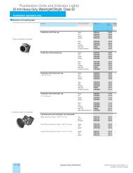
E-<strong>Stop</strong> & <strong>Guard</strong> <strong>Monitoring</strong> <strong>Modules</strong><br />
Easy-to-see red and green LED<br />
status indicators<br />
Detailed<br />
Dimensions<br />
Rugged polycarbonate housing<br />
82.0 mm<br />
Plug-in or fixed terminal blocks<br />
84.0 mm<br />
Standard 35 mm DIN rail track<br />
mounting<br />
118.0 mm<br />
22.5 mm<br />
ES-FA-..AA & GM-FA-10J Models<br />
118.2 mm<br />
ES-FA-6G Models<br />
22.5 mm<br />
84.0 mm<br />
84.0 mm<br />
84.0 mm<br />
118.0 mm<br />
ES-..A-5A Models<br />
45.0 mm<br />
118.0 mm<br />
ES-TN-1H.. Models<br />
45.0 mm<br />
118.0 mm<br />
ES-TN-14H.. Models<br />
67.5 mm<br />
112 More information online at bannerengineering.com
SAFETY MODULES<br />
E-<strong>Stop</strong> and <strong>Guard</strong> <strong>Monitoring</strong> <strong>Modules</strong><br />
E-<strong>Stop</strong> & <strong>Guard</strong> <strong>Monitoring</strong> <strong>Modules</strong><br />
Download<br />
PDF<br />
Model<br />
Functional<br />
<strong>Stop</strong><br />
Category<br />
Supply<br />
Voltage<br />
Inputs<br />
Safety<br />
Outputs<br />
Output<br />
Rating<br />
Aux.<br />
Outputs<br />
Output<br />
Response<br />
Time<br />
Delay<br />
Data<br />
Sheet<br />
GM-FA-10J 0 24V ac/dc<br />
1 NC (single)<br />
or<br />
1 NC & 1 NO<br />
(dual)<br />
2 NO 6 amps — 35 ms — 60998<br />
ES-FA-9AA<br />
1 NC (single) 3 NO<br />
—<br />
0 24V ac/dc or<br />
6 amps<br />
ES-FA-11AA 2 NC (dual) 2 NO 1 NC<br />
25 ms — 60606<br />
ES-UA-5A<br />
ES-VA-5A<br />
ES-TN-1H5<br />
ES-TN-1H6<br />
ES-TN-1H1<br />
0<br />
115V ac<br />
&<br />
12-24V dc 1 NC (single)<br />
230V ac<br />
&<br />
12-24V dc<br />
or<br />
2 NC (dual)<br />
4 NO 6 amps<br />
1 NC<br />
&<br />
2 PNP<br />
25 ms — 122365<br />
0 - 20 sec.<br />
58697<br />
0 - 200 sec.<br />
0.25 sec.<br />
SAFETY MODULES<br />
PICO-GUARD<br />
CONTROLLERS<br />
ES-TN-1H2<br />
ES-TN-1H3<br />
ES-TN-1H4<br />
ES-TN-1H7<br />
ES-TN-1H8<br />
ES-TN-1H9<br />
ES-TN-1H10<br />
0 & 1 24V dc<br />
1 NC (single)<br />
or<br />
2 NC (dual)<br />
2 NO<br />
&<br />
2 NO<br />
w/delay<br />
4 amps<br />
1 NC<br />
(delayed)<br />
&<br />
1 NC<br />
(immediate)<br />
50 ms<br />
0.5 sec.<br />
1.0 sec.<br />
2.0 sec.<br />
4.0 sec.<br />
6.0 sec.<br />
8.0 sec.<br />
10.0 sec.<br />
61061<br />
E-STOP/GUARD<br />
MONITORING<br />
SAFETY MAT<br />
MONITORING<br />
MUTING<br />
MODULES<br />
EXTENSION<br />
MODULES<br />
INTERFACE<br />
MODULES<br />
ES-TN-1H11<br />
15.0 sec.<br />
ES-TN-1H12<br />
20.0 sec.<br />
ES-TN-14H5<br />
ES-TN-14H6<br />
0 & 1 24V dc<br />
1 NC (single)<br />
or<br />
2 NC (dual)<br />
4 NO<br />
&<br />
4 NO<br />
w/delay<br />
4 amps<br />
1 NC<br />
(delayed)<br />
&<br />
1 NC<br />
(immediate)<br />
50 ms<br />
0 - 20 sec.<br />
0 - 200 sec.<br />
68436<br />
ES-FA-6G 0 24V ac/dc 1 NC (single) 3 NO 6 amps 1 NC 35 ms — 55581<br />
NC = Normally Closed Relay, NO = Normally Open Relay<br />
More information online at bannerengineering.com<br />
113
SAFETY MODULES<br />
E-<strong>Stop</strong> and <strong>Guard</strong> <strong>Monitoring</strong> <strong>Modules</strong><br />
GM-FA-10J <strong>Guard</strong> <strong>Monitoring</strong> Module Specifications<br />
Supply Voltage and Current 24V ac/dc ± 20%<br />
Power consumption: approx. 3 VA / 3 W<br />
Supply Protection Circuitry<br />
Protected against transient voltages and reverse polarity<br />
Output Configuration<br />
Each normally open output channel is a series connection of contacts from two forced-guided (mechanically<br />
linked) relays, K1-K2.<br />
Contacts: AgNi, 5 µm gold-plated<br />
Low Current Rating:<br />
Caution: The 5 µm gold-plated contacts allow the switching of low current/low voltage.<br />
To preserve the gold plating on the contacts, do not exceed the following max. values at any time:<br />
Min. voltage: 1V ac/dc<br />
Max. voltage: 60V<br />
Min. current: 5 mA ac/dc<br />
Max. current: 300 mA<br />
Min. power: 5 mW (5 mVA)<br />
Max. power: 7 W (7 VA)<br />
SAFETY MODULES<br />
PICO-GUARD<br />
CONTROLLERS<br />
E-STOP/GUARD<br />
MONITORING<br />
SAFETY MAT<br />
MONITORING<br />
MUTING<br />
MODULES<br />
EXTENSION<br />
MODULES<br />
INTERFACE<br />
MODULES<br />
Output Response Time<br />
Input Requirements<br />
Simultaneity <strong>Monitoring</strong><br />
High Current Rating:<br />
If higher loads must be switched through one or more of the contacts, the minimum and maximum values<br />
of the contact(s) changes to:<br />
Min. voltage: 15V ac/dc<br />
Max. voltage: 250V ac/dc<br />
Min. current: 30 mA ac/dc<br />
Max. current: 6 A<br />
Min. power: 5 W (5 VA)<br />
Max. power: 200 W (1,500 VA)<br />
Mechanical life: 50,000,000 operations<br />
Electrical life: 150,000 cycles typical, @ 200 W (1,500 VA) switched power, resistive load<br />
Note: Transient suppression is recommended when switching inductive loads. Install suppressors across<br />
load. Never install suppressors across output contacts.<br />
35 milliseconds<br />
Input switch must have a normally closed contact and a normally open contact capable of switching 5 to<br />
50 mA @ 15 to 30 V dc.<br />
Reset switch must have one normally open contact capable of switching 5 to 50 mA @ 15 to 30V dc.<br />
Max. external resistance between terminals S11/S12, S11/S13, S21/S22 and S21/S23: 270 Ω each.<br />
2-Channel operation: 3 seconds<br />
1-Channel operation: infinite<br />
Status Indicators 4 green LEDs: 1 red LED:<br />
Power: power is supplied to Safety Module Fault<br />
Channel 1: inputs satisfied (guard closed)<br />
Channel 2: inputs satisfied (guard closed)<br />
Output: K1 and K2 energized, safety outputs closed<br />
Construction<br />
Polycarbonate housing<br />
Environmental Rating<br />
Rated NEMA 1; IEC IP40, Terminals IP20<br />
Mounting Mounts to standard 35 mm DIN rail track. Safety Module must be installed inside an enclosure rated NEMA 3<br />
(IEC IP54), or better.<br />
Vibration Resistance 10 to 55 Hz @ 0.35 mm displacement per IEC 68-2-6<br />
Operating Conditions Temperature: 0° to +50° C Relative humidity: 90% @ +50° C (non-condensing)<br />
Safety Category<br />
4 per ISO 13849-1 (EN954-1) (depending on application)<br />
Certifications For a list of certifications see page 237.<br />
Wiring Diagrams 1-Channel Coded Magnet Switches: WD043 (p. 271)<br />
2-Channel Positive Opening Switches: WD044 (p. 271)<br />
1-Channel (Multiple <strong>Guard</strong>s): WD045 (p. 272)<br />
2-Channel (Multiple <strong>Guard</strong>s): WD046 (p. 272)<br />
<strong>Guard</strong>ed Machine: WD047 (p. 274)<br />
114 More information online at bannerengineering.com
SAFETY MODULES<br />
E-<strong>Stop</strong> and <strong>Guard</strong> <strong>Monitoring</strong> <strong>Modules</strong><br />
Supply Voltage and Current<br />
Supply Protection Circuitry<br />
Output Configuration<br />
ES-FA-..AA Safety Module Specifications<br />
24V ac/dc, +/- 10%; 50/60Hz<br />
Power consumption: approx. 2 W/2 VA<br />
Protected against transient voltages and reverse polarity<br />
ES-FA-9AA: 3 normally open output channels<br />
ES-FA-11AA: 2 normally open output channels and 1 normally closed auxiliary output channel.<br />
Each normally open output channel is a series connection of contacts from two forced-guided (positiveguided)<br />
relays, K1-K2.<br />
The normally closed contact 31-32 is a parallel connection of contacts from K1-K2.<br />
Contacts: AgNi, 5 µm gold-plated<br />
Low Current Rating:<br />
Caution: The 5 µm gold-plated contacts allow the switching of low current/low voltage.<br />
To preserve the gold plating on the contacts, the following max. values should not be exceeded at any time:<br />
Min. voltage: 1V ac/dc<br />
Max. voltage: 60V<br />
Min. current: 5 mA ac/dc<br />
Max. current: 300 mA<br />
Min. power: 5 mW (5 mVA)<br />
Max. power: 7 W (7 VA)<br />
High Current Rating:<br />
If higher loads must be switched through one or more of the contacts, the minimum and maximum values of<br />
the contact(s) changes to:<br />
Min. voltage: 15V ac/dc<br />
Max. voltage: 250V ac/dc<br />
Min. current: 30 mA ac/dc<br />
Max. current: 6 A (ES-FA-9AA) and 7A (ES-FA-11AA)<br />
Min. power: 5 W (5 VA)<br />
Max. power: 200 W (1,500 VA)<br />
SAFETY MODULES<br />
Output Response Time<br />
Input Requirements<br />
Minimum OFF-State<br />
Recovery Time<br />
Status Indicators<br />
Construction<br />
Environmental Rating<br />
Mechanical life: 50,000,000 operations<br />
Electrical life: ES-FA-9AA: 150,000 operations (typical, @ 200 W (1,500 VA) switched power, resistive load)<br />
ES-FA-11AA: 130,000 operations (typical, @ 200 W (1,750 VA) switched power, resistive load)<br />
Note: Transient suppression is recommended when switching inductive loads. Install suppressors across<br />
load. Never install suppressors across output contacts.<br />
25 milliseconds typical<br />
Input switch must have one or two normally closed contacts capable of switching 40 to 100 mA @ 13 to 27V ac/dc.<br />
Reset switch must have one normally open contact capable of switching 20 to 30 mA @ 13 to 27V ac/dc.<br />
250 milliseconds<br />
3 green LED indicators:<br />
Power ON<br />
K1 energized<br />
K2 energized<br />
Polycarbonate housing<br />
Rated NEMA 1; IEC IP40, Terminals IP20<br />
PICO-GUARD<br />
CONTROLLERS<br />
E-STOP/GUARD<br />
MONITORING<br />
SAFETY MAT<br />
MONITORING<br />
MUTING<br />
MODULES<br />
EXTENSION<br />
MODULES<br />
INTERFACE<br />
MODULES<br />
Mounting Mounts to standard 35 mm DIN rail track. Safety Module must be installed inside an enclosure rated NEMA 3<br />
(IEC IP54), or better.<br />
Vibration Resistance 10 to 55Hz @ 0.35 mm displacement per IEC 68-2-6<br />
Operating Conditions Temperature: 0° to +50° C Relative humidity: 90% @ +50° C (non-condensing)<br />
Certifications For a list of certifications see page 237.<br />
Wiring Diagrams 1-Channel: WD048 (p. 275) 2-Channel: WD049 (p. 276)<br />
More information online at bannerengineering.com<br />
115
SAFETY MODULES<br />
E-<strong>Stop</strong> and <strong>Guard</strong> <strong>Monitoring</strong> <strong>Modules</strong><br />
Supply Voltage and Current<br />
Supply Protection Circuitry<br />
Output Configuration<br />
ES-..A-5A Safety Module Specifications<br />
ES-UA-5A: 115V ac (A1-A2), 12-24V dc, ± 15%, 10% max. ripple (B1-B2)<br />
ES-VA-5A: 230V ac (A1-A2), 12-24V dc, ± 15%, 10% max. ripple (B1-B2)<br />
Power consumption: approx. 7 VA/4 W<br />
Protected against transient voltages and reverse polarity<br />
Outputs (K1 & K2): four redundant (total of eight) safety relay (forced-guided) contacts – AgNi, 5 µm goldplated,<br />
plus 1 normally closed auxiliary monitor output - AgNi, 5 µm gold-plated.<br />
Low Current Rating:<br />
Caution: The 5 µm gold-plated contacts allow the switching of low current/low voltage.<br />
To preserve the gold plating on the contacts, the following max. values should not be exceeded at any time:<br />
Min. voltage: 1V ac/dc<br />
Max. voltage: 60V<br />
Min. current: 5 mA ac/dc<br />
Max. current: 300 mA<br />
Min. power: 5 mW (5 mVA)<br />
Max. power: 7 W (7 VA)<br />
SAFETY MODULES<br />
PICO-GUARD<br />
CONTROLLERS<br />
E-STOP/GUARD<br />
MONITORING<br />
SAFETY MAT<br />
MONITORING<br />
MUTING<br />
MODULES<br />
EXTENSION<br />
MODULES<br />
INTERFACE<br />
MODULES<br />
Output Response Time<br />
Input Requirements<br />
ON-Time Delay<br />
High Current Rating:<br />
If higher loads must be switched through one or more of the contacts, the minimum and maximum values of<br />
the contact(s) changes to:<br />
Min. voltage: 15V ac/dc<br />
Max. voltage: 250V ac/dc<br />
Min. current: 30 mA ac/dc<br />
Max. current: 6 A<br />
Min. power: 5 W (5 VA)<br />
Max. power: 200 W (1,500 VA)<br />
Mechanical life: 50,000,000 operations<br />
Electrical life: 150,000 operations (typical, @ 1,500 VA switched power, resistive load)<br />
150,000 operations (typical, @ 200 W switched power, resistive load)<br />
Note: Transient suppression is recommended when switching inductive loads. Install suppressors across<br />
load. Never install suppressors across output contacts.<br />
Solid-State Monitor Outputs:<br />
- Two non-safety solid-state dc outputs<br />
- Output at Y32 monitors state of outputs – conducts (output high) when both K1 and K2 are energized<br />
- Output at Y35 conducts (output high) when internal power supply is OK<br />
- Output circuits require application of +12-24V dc ±15% at terminal Y31; dc common at Y30<br />
- Maximum switching current: 100 mA at 12-24V dc<br />
- Both outputs are protected against short circuits<br />
25 milliseconds typical<br />
Input switch must have normally closed contacts each capable of switching 20 to 50 mA @ 12 to 30V dc;<br />
and must be open ≥10 milliseconds for a valid stop command.<br />
Reset switch must have one normally open contact capable of switching 20 to 50 mA @ 12 to 30V ac/dc.<br />
80 milliseconds; time from the E-stop contacts to close (Auto Reset) or the reset button to open (Manual<br />
Reset) and the safety outputs to close.<br />
Status Indicators 3 green LED indicators: 1 Red LED indicator:<br />
Power ON<br />
Fault (internal power supply, ground fault,<br />
K1 energized<br />
short across the input channels or other<br />
K2 energized<br />
internal failures)<br />
Construction<br />
Polycarbonate housing<br />
Environmental Rating<br />
Rated NEMA 1; IEC IP20<br />
Mounting Mounts to standard 35 mm DIN rail track. Safety Module must be installed inside an enclosure rated NEMA 3<br />
(IEC IP54), or better.<br />
Vibration Resistance 10 to 55Hz @ 0.35 mm displacement per IEC 68-2-6<br />
Operating Conditions Temperature: 0° to +50° C Relative humidity: 90% @ +50° C (non-condensing)<br />
Certifications For a list of certifications see page 237.<br />
Wiring Diagrams 1-Channel: WD050 (p. 277) 2-Channel: WD051 (p. 278)<br />
116 More information online at bannerengineering.com
E-<strong>Stop</strong> and <strong>Guard</strong> <strong>Monitoring</strong> <strong>Modules</strong><br />
ES-TN-1H.. Safety Module Specifications<br />
Supply Voltage and Current 24V dc, ±20%<br />
Power consumption: approx. 5 W<br />
Supply Protection Circuitry<br />
Protected against transient voltages and reverse polarity<br />
SAFETY MODULES<br />
Output Configuration<br />
Outputs K1& K2: Two redundant (total of four) safety relay (forced-guided) contacts – AgNi, gold flashed<br />
one auxiliary normally closed contact – AgNi, gold flashed<br />
Outputs K3 &K4: Two redundant (total of four) delayed relay (forced-guided) contacts – AgNi, gold flashed<br />
one auxiliary normally closed contact – AgNi, gold flashed<br />
Contact ratings (all normally open and normally closed output contacts):<br />
Max. voltage: 250V ac or 250V dc<br />
Max. current: 4 A ac or dc<br />
Min. current: 30 mA @ 24V dc<br />
Max. power: 1000 VA, 100 W<br />
Mechanical life: 50,000,000 operations<br />
Electrical life: 100,000 at full resistive load<br />
Output Response Time<br />
Input Requirements<br />
ON-Time Delay<br />
NOTE: Transient suppression is recommended when switching inductive loads. Install suppressors across<br />
load. Never install suppressors across output contacts.<br />
K1 &K2: 50 milliseconds typical<br />
K3 &K4 (ES-TN-1H1): 0.25 second<br />
K3 &K4 (ES-TN-1H2): 0.5 second<br />
K3 &K4 (ES-TN-1H3): 1.0 second<br />
K3 &K4 (ES-TN-1H4): 2.0 seconds<br />
K3 & K4 (ES-TN-1H5): 0, 0.5, 1, 2, 4, 6, 8, 10, 15, 20 seconds<br />
K3 & K4 (ES-TN-1H6): 0, 5, 10, 20, 30, 50, 70, 100, 150, 200 seconds<br />
K3 &K4 (ES-TN-1H7): 4.0 seconds<br />
K3 &K4 (ES-TN-1H8): 6.0 seconds<br />
K3 &K4 (ES-TN-1H9): 8.0 seconds<br />
K3 &K4 (ES-TN-1H10): 10.0 seconds<br />
K3 &K4 (ES-TN-1H11): 15.0 seconds<br />
K3 &K4 (ES-TN-1H12): 20.0 seconds<br />
Delayed Output Timing Tolerance: Set time ±100 milliseconds or ±2%, whichever is greater<br />
Input switch must have a normally closed contact capable of switching 20 mA @ 24V dc.<br />
Reset switch must have one normally open contact capable of switching 20 mA @ 24V dc.<br />
NOTE: Inputs must be voltage-free, dry contacts.<br />
≥ 100 milliseconds; time from the E-stop contacts to close (Auto Reset) or the Reset button to open (Manual<br />
Reset) and the safety outputs to close.<br />
Status Indicators 6 green LED indicators: 1 red LED indicator:<br />
Power Monitor Fault<br />
E-<strong>Stop</strong> Out (K1 &K2 ON/OFF)<br />
Reset Timed-Out (K3 & K4 ON/OFF)<br />
Construction<br />
Polycarbonate housing<br />
SAFETY MODULES<br />
PICO-GUARD<br />
CONTROLLERS<br />
E-STOP/GUARD<br />
MONITORING<br />
SAFETY MAT<br />
MONITORING<br />
MUTING<br />
MODULES<br />
EXTENSION<br />
MODULES<br />
INTERFACE<br />
MODULES<br />
Environmental Rating<br />
Rated NEMA 1; IEC IP40, Terminals IP20, max. terminal torque 0.8 Nm<br />
Mounting Mounts to standard 35 mm DIN rail track. Safety Module must be installed inside an enclosure rated NEMA 3<br />
(IEC IP54), or better.<br />
Vibration Resistance 10 to 55Hz @ 0.35 mm displacement per IEC 68-2-6<br />
Operating Conditions Temperature: 0° to +50° C Relative humidity: 90% @ +50° C (non-condensing)<br />
Certifications For a list of certifications see page 237.<br />
Wiring Diagrams 2-Channel: WD052 (p. 279)<br />
More information online at bannerengineering.com<br />
117